EP2780903B1 - Fastening clip, hingeably and/or method - Google Patents
Fastening clip, hingeably and/or method Download PDFInfo
- Publication number
- EP2780903B1 EP2780903B1 EP12839160.4A EP12839160A EP2780903B1 EP 2780903 B1 EP2780903 B1 EP 2780903B1 EP 12839160 A EP12839160 A EP 12839160A EP 2780903 B1 EP2780903 B1 EP 2780903B1
- Authority
- EP
- European Patent Office
- Prior art keywords
- wristband
- closure
- closing body
- base body
- closing
- Prior art date
- Legal status (The legal status is an assumption and is not a legal conclusion. Google has not performed a legal analysis and makes no representation as to the accuracy of the status listed.)
- Not-in-force
Links
Images

Classifications
-
- G—PHYSICS
- G09—EDUCATION; CRYPTOGRAPHY; DISPLAY; ADVERTISING; SEALS
- G09F—DISPLAYING; ADVERTISING; SIGNS; LABELS OR NAME-PLATES; SEALS
- G09F3/00—Labels, tag tickets, or similar identification or indication means; Seals; Postage or like stamps
- G09F3/005—Identification bracelets, e.g. secured to the arm of a person
-
- A—HUMAN NECESSITIES
- A44—HABERDASHERY; JEWELLERY
- A44C—PERSONAL ADORNMENTS, e.g. JEWELLERY; COINS
- A44C5/00—Bracelets; Wrist-watch straps; Fastenings for bracelets or wrist-watch straps
- A44C5/18—Fasteners for straps, chains or the like
- A44C5/20—Fasteners for straps, chains or the like for open straps, chains or the like
-
- G—PHYSICS
- G09—EDUCATION; CRYPTOGRAPHY; DISPLAY; ADVERTISING; SEALS
- G09F—DISPLAYING; ADVERTISING; SIGNS; LABELS OR NAME-PLATES; SEALS
- G09F3/00—Labels, tag tickets, or similar identification or indication means; Seals; Postage or like stamps
- G09F3/02—Forms or constructions
- G09F3/0286—Forms or constructions provided with adaptations for labelling machines
-
- G—PHYSICS
- G09—EDUCATION; CRYPTOGRAPHY; DISPLAY; ADVERTISING; SEALS
- G09F—DISPLAYING; ADVERTISING; SIGNS; LABELS OR NAME-PLATES; SEALS
- G09F3/00—Labels, tag tickets, or similar identification or indication means; Seals; Postage or like stamps
- G09F3/02—Forms or constructions
- G09F3/03—Forms or constructions of security seals
- G09F3/0305—Forms or constructions of security seals characterised by the type of seal used
- G09F3/0323—Forms or constructions of security seals characterised by the type of seal used having clamp-like sealing means
-
- G—PHYSICS
- G09—EDUCATION; CRYPTOGRAPHY; DISPLAY; ADVERTISING; SEALS
- G09F—DISPLAYING; ADVERTISING; SIGNS; LABELS OR NAME-PLATES; SEALS
- G09F3/00—Labels, tag tickets, or similar identification or indication means; Seals; Postage or like stamps
- G09F3/08—Fastening or securing by means not forming part of the material of the label itself
- G09F3/16—Fastening or securing by means not forming part of the material of the label itself by clamps
-
- G—PHYSICS
- G09—EDUCATION; CRYPTOGRAPHY; DISPLAY; ADVERTISING; SEALS
- G09F—DISPLAYING; ADVERTISING; SIGNS; LABELS OR NAME-PLATES; SEALS
- G09F3/00—Labels, tag tickets, or similar identification or indication means; Seals; Postage or like stamps
- G09F3/02—Forms or constructions
- G09F2003/0201—Label sheets intended to be introduced in a printer, e.g. laser printer
Definitions
- the present invention relates to a wristband closure for providing a closure for a wristband.
- the present invention further provides a semi-finished product comprising a number of wristbands according to the present invention arranged on a substrate.
- the present invention further provides a method for manufacturing and/or processing a semi-finished product according to the present invention.
- Document DE 10 2005 001359 Al discloses a closure for a wristband that can be closed about the wristband and that provides a sliding protection by means of pointy pins.
- Document US 6 684 462 B1 provides a tying system for tying together ropes, strips or cords. Retention services are provided for retaining the ropes, strips or cords.
- Document DE 10 2009 021 748 Al discloses a reusable band closure for multiple usage with several persons.
- Document JP 2007 148066 A provides a closure that can be used with a band that has an array of mutually identically spaced fastening openings at both ends of the band for functioning with fastening pins of their closure.
- the present application has the advantage that, due to the pivoting action, closing of a hinge clip is exceptionally practical for the person performing the closing.
- the present wristband closure has the advantage of it being possible to arrange the clip flat against the wrist during use thereof, this resulting in an increased wearer comfort, in addition to further advantages as stated in the above-mentioned patent application.
- the wristband closure comprises a hinge comprising at least one shaft element and at least one shaft holder.
- the pivotable connection is hereby embodied in advantageous manner.
- the base body more preferably forms a shaft holder and the closing body comprises a shaft element. It hereby becomes possible to give the closing body a relatively thin form compared to the base body, this providing the further advantage that there is space in the relatively thick base body to attach the wristband thereto.
- the base body comprises a central part and a bottom part mounted or mountable thereon, between which the wristband can be arranged, preferably between which the wristband is permanently attached by means of fixation, such as by means of ultrasonic welding or adhesion.
- fixation such as by means of ultrasonic welding or adhesion.
- Ultrasonic welding further provides a very firm permanent connection between parts of the bottom part and the central part which together form the shaft holder of the hinge.
- a robust hinge is hereby realized.
- the at least one shaft holder is more preferably formed by parts of the central part and the bottom part.
- the side opposite the hinge is provided with a snap closure connection comprising at least one snap-in element which is enclosed in the base body once it has been snapped in.
- a snap closure connection comprising at least one snap-in element which is enclosed in the base body once it has been snapped in.
- indicator means such as weakening means, such as openings passing partially through the material such as at least one gap-like opening, for the purpose of weakening the attachment between the base body and the closing body, preferably as according to claim 6 by weakening the connection between the at least one snap-in element and the body, preferably the closing body, to which it is attached.
- the closure breaks loose in visible manner, whereby it is on the one hand non-reclosable and on the other the line of the break is clearly visible in preferably the upper surface of the closing body.
- Possible manipulation of the wristband closure can hereby be determined by means of a quick and simple visual check.
- the wristband closure preferably comprises screening means for at least partially screening lateral view of or access to the space between the base body and the closing body, the screening elements preferably being arranged on the closing body.
- the wristband closure preferably comprises screening elements for at least partially screening lateral view of or access to the space between the central part and the bottom part, the screening elements preferably being arranged on the bottom part.
- the closing body, the central part and/or the bottom part comprise mutually coacting retention members for preferably providing a retention action in respect of the wristband, wherein the retention members preferably comprise protruding elements such as pins and corresponding receiving elements such as openings.
- the wristband preferably comprise protruding elements such as pins and corresponding receiving elements such as openings.
- the central part and the bottom part are more preferably connected to each other by means of a material bridge for the purpose of providing a flexible or breakable mutual connection.
- a material bridge for the purpose of providing a flexible or breakable mutual connection.
- the wristband closure is preferably manufactured from a single material, preferably by means of a moulding process such as an injection moulding process, wherein the closing body and/or the bottom part is more preferably provided with a tamper-proof indicator, such as of breakage of the closing body or the bottom part during attempts at manipulation thereof, which is preferably embodied as weakened portions or break lines.
- a tamper-proof indicator such as of breakage of the closing body or the bottom part during attempts at manipulation thereof, which is preferably embodied as weakened portions or break lines.
- a further aspect according to the present invention relates to a semi-finished product comprising a predetermined number of wristbands and a number of wristband closures connected to the wristbands, wherein the wristbands and/or the wristband closures are arranged removably on a substrate member for providing a relative placing of the wristbands. It hereby becomes possible to print blank wristbands with information, wherein the position and/or arrangement of the wristbands is known relative to the substrate.
- the assembly of the substrate member and the wristbands is more preferably suitable for processing by means of a printer, such as an offset printer, screen printer, inkjet printer and the like.
- a printer such as an offset printer, screen printer, inkjet printer and the like.
- a further aspect according to the present invention relates to a method for manufacturing and/or processing a semi-finished product according to one more of the foregoing claims, comprising steps for:
- the method more preferably comprises steps for providing the wristbands adhered to the substrate with an imprint by means of a printer.
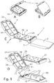
- a first preferred embodiment relates to a wristband closure or wrist clip 1.
- This comprises a base body comprising a bottom part 2 and a central part 3.
- both these parts are welded ultrasonically to each other by means of the mutually contacting parts 13, 15 and 14.
- Parts 13 together with the abutting parts of rounded portions 16 form the hinge, or at least the shaft holder of the hinge.
- the pins 15 serve to pierce an end part 51 ( Fig. 3 ) of the wristband and as welding material for ultrasonic welding for the purpose of attaching bottom part 2 to central part 3.
- Protrusions 14 likewise serve as welding material.
- the bottom part and the central part are attached to each other.
- the end part 51 is located here between these two parts.
- the bottom part comprises upright edges 19 which, when the bottom part is welded fixedly to the central part, ensure that viewing or the possibility of inserting manipulation means is limited or minimized.
- the central part has chamfered edges 29 on either side for guiding material of the wristband.
- the central part also has pins 27 which protrude into the wristband when it is arranged between the base body and the closing body.
- the end part 51 of the wristband and the bottom part and the central part are therefore integrated with the closing body 4 pivotable relative thereto.
- the closing body has on one side the hinge shaft 11 which is strengthened by the connecting elements 17 and the rest of the closing body.
- the closing body is pivotable relative to the bottom part by means of this hinge shaft.
- the closing body further has upright edges 29 on either side which likewise have the purpose of limiting or minimizing access to the interior.
- the closing body is provided with pins 26 which can extend through openings 28 in the base body.
- the part of the wristband arranged in this space is hereby retained in effective manner.
- the base body On the opposite side relative to the hinge the base body has two openings bounded by an edge 21 for retaining the snapped-in members of the closing body.
- two openings with two associated snap-in elements so that, when a manipulation attempt is made, only one of the snap-in elements will be broken. This, in coaction with the weakening lines 34 in the closing body, will cause the closing body to break, whereby the manipulation becomes visible.
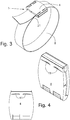
- FIG. 4 A further means according to the present invention for showing that manipulation has taken place is shown in Fig. 4 .
- the closing body here has two openings 41 which weaken the connection between the closing body and the snap elements.
- the advantage hereof is that, when an attempt is made to open the closing body, the closing body will break at the location of the opening and the snap element on the side where manipulation is taking place.
- An alternative hereto is a weakened portion 25 on the underside of the snap element whereby, when a snap-in element is broken, the closing body will break at the weakening lines 34, whereby the manipulation becomes visible.
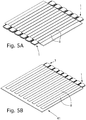
- Fig. 5A and Fig. 5B show a semi-finished product of substrate sheets 41 with wristbands 8 adhered thereto having a wristband closure on one end thereof. It is an advantage of this semi-finished product that either wristbands or neutrally coloured wristbands can be applied which can be printed with a suitable pattern for an occasion. This provides a high measure of flexibility in respect of customizing the wristbands for specific occasions. This provides great advantages in production.
Landscapes
- Engineering & Computer Science (AREA)
- Physics & Mathematics (AREA)
- General Physics & Mathematics (AREA)
- Theoretical Computer Science (AREA)
- Computer Security & Cryptography (AREA)
- Professional, Industrial, Or Sporting Protective Garments (AREA)
Description
- The present invention relates to a wristband closure for providing a closure for a wristband. The present invention further provides a semi-finished product comprising a number of wristbands according to the present invention arranged on a substrate. The present invention further provides a method for manufacturing and/or processing a semi-finished product according to the present invention. [insert page 1a]
- The above stated patent application provides per se a characterizing improvement relative to the prior art. In order to add still further improvements to the prior art, the present invention relates to a wristband with closure according to
claim 1. - To be inserted on
page 1 after line 16:
DocumentDE 10 2005 001359 Al discloses a closure for a wristband that can be closed about the wristband and that provides a sliding protection by means of pointy pins. DocumentUS 6 684 462 B1 provides a tying system for tying together ropes, strips or cords. Retention services are provided for retaining the ropes, strips or cords. DocumentDE 10 2009 021 748 Al discloses a reusable band closure for multiple usage with several persons. DocumentJP 2007 148066 A - In addition to the stated advantages, the present application has the advantage that, due to the pivoting action, closing of a hinge clip is exceptionally practical for the person performing the closing. In addition, the present wristband closure has the advantage of it being possible to arrange the clip flat against the wrist during use thereof, this resulting in an increased wearer comfort, in addition to further advantages as stated in the above-mentioned patent application.
- In a first preferred embodiment according to the present invention the wristband closure comprises a hinge comprising at least one shaft element and at least one shaft holder. The pivotable connection is hereby embodied in advantageous manner.
- The base body more preferably forms a shaft holder and the closing body comprises a shaft element. It hereby becomes possible to give the closing body a relatively thin form compared to the base body, this providing the further advantage that there is space in the relatively thick base body to attach the wristband thereto.
- In a further preferred embodiment the base body comprises a central part and a bottom part mounted or mountable thereon, between which the wristband can be arranged, preferably between which the wristband is permanently attached by means of fixation, such as by means of ultrasonic welding or adhesion. An advantageous further attachment of the wristband is hereby provided. Ultrasonic welding further provides a very firm permanent connection between parts of the bottom part and the central part which together form the shaft holder of the hinge. A robust hinge is hereby realized. In the wristband closure the at least one shaft holder is more preferably formed by parts of the central part and the bottom part.
- In order to provide a wristband closure for once-only closing during use, the side opposite the hinge is provided with a snap closure connection comprising at least one snap-in element which is enclosed in the base body once it has been snapped in. These more preferably comprise indicator means, such as weakening means, such as openings passing partially through the material such as at least one gap-like opening, for the purpose of weakening the attachment between the base body and the closing body, preferably as according to
claim 6 by weakening the connection between the at least one snap-in element and the body, preferably the closing body, to which it is attached. Hereby realized is that, when an attempt is made to open the wristband closure, the closure breaks loose in visible manner, whereby it is on the one hand non-reclosable and on the other the line of the break is clearly visible in preferably the upper surface of the closing body. Possible manipulation of the wristband closure can hereby be determined by means of a quick and simple visual check. - In order to further improve the security thereof, the wristband closure preferably comprises screening means for at least partially screening lateral view of or access to the space between the base body and the closing body, the screening elements preferably being arranged on the closing body. For this same purpose the wristband closure preferably comprises screening elements for at least partially screening lateral view of or access to the space between the central part and the bottom part, the screening elements preferably being arranged on the bottom part.
- In a further embodiment the closing body, the central part and/or the bottom part comprise mutually coacting retention members for preferably providing a retention action in respect of the wristband, wherein the retention members preferably comprise protruding elements such as pins and corresponding receiving elements such as openings. It hereby becomes possible for the wristband to be retained in secure manner relative to the wristband closure. This is particularly advantageous for the part of the wristband which is arranged during use between the base body and the closing body, at least in embodiments wherein an end part of the wristband is attached in fixed manner to the base body. This fixation provides a high measure of security for this end part of the wristband. The retention members contribute toward a high measure of security of fixation of a part of the wristband between the base body and the closing body in that they substantially extend wholly or partially through the wristband.
- The central part and the bottom part are more preferably connected to each other by means of a material bridge for the purpose of providing a flexible or breakable mutual connection. Hereby realized is that between the moment of production and the moment of assembly the components are kept together by this material bridge. A further advantage here is that the whole device can be manufactured by means of an injection moulding operation.
- The wristband closure is preferably manufactured from a single material, preferably by means of a moulding process such as an injection moulding process, wherein the closing body and/or the bottom part is more preferably provided with a tamper-proof indicator, such as of breakage of the closing body or the bottom part during attempts at manipulation thereof, which is preferably embodied as weakened portions or break lines. This effectively realizes that, when a user attempts to manipulate, the closing body would be damaged in visible manner in that for instance a part breaks off between the break lines.
- A further aspect according to the present invention relates to a semi-finished product comprising a predetermined number of wristbands and a number of wristband closures connected to the wristbands, wherein the wristbands and/or the wristband closures are arranged removably on a substrate member for providing a relative placing of the wristbands. It hereby becomes possible to print blank wristbands with information, wherein the position and/or arrangement of the wristbands is known relative to the substrate.
- The assembly of the substrate member and the wristbands is more preferably suitable for processing by means of a printer, such as an offset printer, screen printer, inkjet printer and the like.
- A further aspect according to the present invention relates to a method for manufacturing and/or processing a semi-finished product according to one more of the foregoing claims, comprising steps for:
- providing a wristband closure with a band part attached thereto;
- providing a substrate such as a sheet of paper and/or plastic;
- adhering the wristbands and/or the wristband closure to the substrate, preferably by means of a releasable adhesion, in a relative placing preferably suitable for passage through a printer.
- Applying such a method makes it possible by means of a production process to produce a blank semi-finished product in large quantities which, subject to the demand, can be personalized in a very short throughput time.
- The method more preferably comprises steps for providing the wristbands adhered to the substrate with an imprint by means of a printer.
- Further advantages, features and details of the present invention will be described in greater detail hereinbelow on the basis of one or more preferred embodiments and with reference to the accompanying figures. Similar though not necessarily identical components of different preferred embodiments are designated with the same reference numerals.
-
Fig. 1A-D show four perspective views of a first preferred embodiment according to the present invention. -
Fig. 2A-D show four further views of the embodiment according toFig. 1 . -
Fig. 3 shows a view of a further preferred embodiment in a situation of use. -
Fig. 4 shows a perspective view of a further preferred embodiment according to the present invention. -
Fig. 5 shows two perspective views of a further preferred embodiment according to the present invention. - A first preferred embodiment (
Fig. 1 ) according to the present invention relates to a wristband closure orwrist clip 1. This comprises a base body comprising abottom part 2 and acentral part 3. During use both these parts are welded ultrasonically to each other by means of the mutually contactingparts Parts 13 together with the abutting parts ofrounded portions 16 form the hinge, or at least the shaft holder of the hinge. Thepins 15 serve to pierce an end part 51 (Fig. 3 ) of the wristband and as welding material for ultrasonic welding for the purpose of attachingbottom part 2 tocentral part 3.Protrusions 14 likewise serve as welding material. Hereby described is how the bottom part and the central part are attached to each other. During use theend part 51 is located here between these two parts. - The bottom part comprises
upright edges 19 which, when the bottom part is welded fixedly to the central part, ensure that viewing or the possibility of inserting manipulation means is limited or minimized. - The central part has chamfered
edges 29 on either side for guiding material of the wristband. The central part also haspins 27 which protrude into the wristband when it is arranged between the base body and the closing body. - When the wristband is provided to the user, the
end part 51 of the wristband and the bottom part and the central part are therefore integrated with theclosing body 4 pivotable relative thereto. - The closing body has on one side the
hinge shaft 11 which is strengthened by the connectingelements 17 and the rest of the closing body. The closing body is pivotable relative to the bottom part by means of this hinge shaft. The closing body further has upright edges 29 on either side which likewise have the purpose of limiting or minimizing access to the interior. - The closing body is provided with
pins 26 which can extend throughopenings 28 in the base body. The part of the wristband arranged in this space is hereby retained in effective manner. - On the opposite side relative to the hinge the base body has two openings bounded by an
edge 21 for retaining the snapped-in members of the closing body. Provided are two openings with two associated snap-in elements so that, when a manipulation attempt is made, only one of the snap-in elements will be broken. This, in coaction with the weakeninglines 34 in the closing body, will cause the closing body to break, whereby the manipulation becomes visible. - A further means according to the present invention for showing that manipulation has taken place is shown in
Fig. 4 . The closing body here has twoopenings 41 which weaken the connection between the closing body and the snap elements. The advantage hereof is that, when an attempt is made to open the closing body, the closing body will break at the location of the opening and the snap element on the side where manipulation is taking place. An alternative hereto is a weakenedportion 25 on the underside of the snap element whereby, when a snap-in element is broken, the closing body will break at the weakening lines 34, whereby the manipulation becomes visible. - For the purpose of holding the central part and the bottom part in advantageous mutual arrangement during production, they are mutually coupled by a
film hinge 5 during injection moulding. -
Fig. 5A and Fig. 5B show a semi-finished product ofsubstrate sheets 41 withwristbands 8 adhered thereto having a wristband closure on one end thereof. It is an advantage of this semi-finished product that either wristbands or neutrally coloured wristbands can be applied which can be printed with a suitable pattern for an occasion. This provides a high measure of flexibility in respect of customizing the wristbands for specific occasions. This provides great advantages in production. - The present invention has been described in the foregoing on the basis of several preferred embodiments. Different aspects of different embodiments are deemed described in combination with each other, wherein all combinations which can be deemed by a skilled person in the field as falling within the scope of the invention on the basis of reading of this document are included. These preferred embodiments are not limitative for the scope of protection of this document. The rights sought are defined in the appended claims.
Claims (15)
- A wristband with closure (1) providing a tamper-proof closure for a wristband (8), comprising a wristband (8) and a wristband closure (1), wherein the wristband closure comprises:- a base body (2,3) holding a part, preferably an end part, of the wristband;- a closing body (4) for closing the wristband by means of receiving a further part of the wristband between the base body and the closing body;- a closing assembly for providing an enclosed closure between the base body and the closing body on one side of the wristband closure;- a hinge assembly for providing a pivotable connection between the base body and the closing body (4) on an opposite side, the closing assembly providing a once only closing by comprising a snap closure connection comprising at least one snap-in element (24) which is enclosed in the base body once it has been snapped in.
- Wristband with closure as claimed in claim 1, comprising a hinge comprising at least one shaft element (11) and at least one shaft holder (12).
- Wristband with closure as claimed in claim 1 or 2, wherein the base body forms a shaft holder (12) and the closing body comprises a shaft element (11).
- Wristband with closure as claimed in claim 1 or 2, wherein the base body comprises a central part (3) and a bottom part (2) mounted or mountable thereon, between which the wristband can be arranged, preferably between which the wristband (8) is permanently attached by means of fixation, such as by means of ultrasonic welding or adhesion.
- Wristband with closure as claimed in claim 4, wherein the at least one shaft holder is formed by parts of the central part and the bottom part.
- Wristband with closure as claimed in one or more of the foregoing claims, wherein the side opposite the hinge is provided with the snap closure .
- Wristband with closure as claimed in one or more of the foregoing claims, comprising indicator means (34), such as weakening means, such as openings passing partially through the material such as at least one gap-like opening, for the purpose of weakening the attachment between the base body and the closing body, preferably as according to claim 6, by weakening the connection between the at least one snap-in element and the body, preferably the closing body, to which it is attached.
- Wristband with closure as claimed in one or more of the foregoing claims, comprising screening means (29) for screening lateral view of or access to the space between the base body and the closing body, the screening elements preferably being arranged on the closing body.
- Wristband with closure as claimed in one or more of the foregoing claims 4-8, comprising screening elements (19) for screening lateral view of or access to the space between the central part and the bottom part, the screening elements preferably being arranged on the bottom part.
- Wristband with closure as claimed in one or more of the foregoing claims, wherein the base body, the closing body, the central part and/or the bottom part comprise mutually coacting retention members for providing a retention action in respect of the wrist-band, wherein the retention members preferably comprise protruding elements such as pins (15,26) and corresponding receiving elements such as openings (28).
- Wristband with closure as claimed in claim 9 or 10, wherein the central part and the bottom part are connected to each other by means of a material bridge for the purpose of providing a flexible or breakable mutual connection.
- Wristband with closure as claimed in one or more of the foregoing claims 10 or 11, wherein the protruding elements (15,26) extend during use of the wristband closure into and/or beyond material of the wristband and/or the wristband closure comprises cover elements for covering a passage for the wristband at the passage between the base body and the closing body.
- Wristband with closure as claimed in one or more of the foregoing claims, characterized in that the wristband closure (1) is manufactured from a single material, preferably by means of a moulding process such as an injection moulding process, wherein the closing body and/or the bottom part is more preferably provided with a tamper-proof indicator, such as of breakage of the closing body or the bottom part during attempts at manipulation thereof, which is preferably embodied as weakened portions or break lines.
- Method for manufacturing and/or processing the wristband with closure as claimed in one more of the foregoing claims, comprising steps for:- providing a wristband with closure with a band part attached thereto;- providing a substrate such as a sheet of paper and/or plastic;- adhering the wristbands and/or the wristband closure to the substrate, preferably by means of a releasable adhesion, in a relative placing preferably suitable for passage through a printer.
- Method as claimed in claim 14, comprising steps for providing the wristbands adhered to the substrate with an imprint by means of a printer.
Applications Claiming Priority (2)
| Application Number | Priority Date | Filing Date | Title |
|---|---|---|---|
| NL2007820A NL2007820C2 (en) | 2011-11-18 | 2011-11-18 | CONFIRMATION CLIP, HINGED AND / OR METHOD. |
| PCT/NL2012/050823 WO2013095100A1 (en) | 2011-11-18 | 2012-11-19 | Fastening clip, hingeably and/or method |
Publications (2)
| Publication Number | Publication Date |
|---|---|
| EP2780903A1 EP2780903A1 (en) | 2014-09-24 |
| EP2780903B1 true EP2780903B1 (en) | 2021-11-17 |
Family
ID=47891838
Family Applications (1)
| Application Number | Title | Priority Date | Filing Date |
|---|---|---|---|
| EP12839160.4A Not-in-force EP2780903B1 (en) | 2011-11-18 | 2012-11-19 | Fastening clip, hingeably and/or method |
Country Status (3)
| Country | Link |
|---|---|
| EP (1) | EP2780903B1 (en) |
| NL (1) | NL2007820C2 (en) |
| WO (1) | WO2013095100A1 (en) |
Families Citing this family (2)
| Publication number | Priority date | Publication date | Assignee | Title |
|---|---|---|---|---|
| GB201312685D0 (en) * | 2013-07-16 | 2013-08-28 | Id & C Ltd | Fastening Device |
| EP3568844A1 (en) * | 2017-01-14 | 2019-11-20 | Carlier Group B.V. | Wristband and method |
Family Cites Families (5)
| Publication number | Priority date | Publication date | Assignee | Title |
|---|---|---|---|---|
| US6684462B1 (en) * | 2002-06-10 | 2004-02-03 | Dipak Narula | Tying fastener |
| DE102005001359A1 (en) * | 2005-01-11 | 2006-07-20 | Weiss, Manfred | Single-piece sealing device for identity tape with tape stoppers on stopper carriers allows a tape to be closed with thumb pressure without a tool |
| JP4666625B2 (en) * | 2005-11-29 | 2011-04-06 | 株式会社サトー | Wristband clip |
| US8074389B2 (en) * | 2009-05-05 | 2011-12-13 | Laser Band, Llc | Wristband with separated imaging area and cinch slot |
| DE102009021748B4 (en) * | 2009-05-18 | 2016-11-03 | Sigel Gmbh | Clasp for an information band |
-
2011
- 2011-11-18 NL NL2007820A patent/NL2007820C2/en not_active IP Right Cessation
-
2012
- 2012-11-19 WO PCT/NL2012/050823 patent/WO2013095100A1/en not_active Ceased
- 2012-11-19 EP EP12839160.4A patent/EP2780903B1/en not_active Not-in-force
Non-Patent Citations (1)
| Title |
|---|
| None * |
Also Published As
| Publication number | Publication date |
|---|---|
| EP2780903A1 (en) | 2014-09-24 |
| WO2013095100A1 (en) | 2013-06-27 |
| NL2007820A (en) | 2013-05-23 |
| NL2007820C2 (en) | 2013-09-03 |
Similar Documents
| Publication | Publication Date | Title |
|---|---|---|
| EP2152160B1 (en) | A closure mechanism for an identification medium adapted for receiving indicia forming material and dual closure means | |
| CA2667271C (en) | Wristband with snap closure and patient id label | |
| US10997874B1 (en) | Combination wristband and label form | |
| US10297170B2 (en) | Combination wristband and label form | |
| EP2273899B1 (en) | Wrap around self laminating wristband | |
| US12170033B1 (en) | Single ply wristband with printable coating | |
| US20090094872A1 (en) | Laser wristband tags | |
| US9355577B1 (en) | Unitary flexible tag article | |
| US12142166B1 (en) | Wristband label form with uneven lamination panels | |
| EP2780903B1 (en) | Fastening clip, hingeably and/or method | |
| EP3006367A1 (en) | Sealing label with identification function and container wrapped with said sealing label | |
| EP2572345A1 (en) | Fastening clip for a wristband | |
| US11557228B1 (en) | Wristband and label form | |
| US20090152860A1 (en) | Protective label | |
| US10325525B1 (en) | Combination wristband and label form | |
| US20120125958A1 (en) | Disposable lanyard for suspending object | |
| US12387626B1 (en) | Business form and methods of making and using same | |
| WO2016066710A1 (en) | Tamper-proof form | |
| ES2428029T3 (en) | Label templates and adhesive brochures | |
| ITMI20110418A1 (en) | SELF-ADHESIVE LABEL APPLICABLE TO AN OBJECT AND WITH AT LEAST AN REMOVABLE AND APPLICABLE PORTION WITH ANOTHER OBJECT. | |
| NZ591454A (en) | Tag from flat waterproof material, with resilient head to be bent to pass through aperture to form looped tag, typically as plant label | |
| ITBO20070241A1 (en) | BRACELET FOR THE UNIQUE IDENTIFICATION OF DISTINCT UNITS. |
Legal Events
| Date | Code | Title | Description |
|---|---|---|---|
| PUAI | Public reference made under article 153(3) epc to a published international application that has entered the european phase |
Free format text: ORIGINAL CODE: 0009012 |
|
| 17P | Request for examination filed |
Effective date: 20140618 |
|
| AK | Designated contracting states |
Kind code of ref document: A1 Designated state(s): AL AT BE BG CH CY CZ DE DK EE ES FI FR GB GR HR HU IE IS IT LI LT LU LV MC MK MT NL NO PL PT RO RS SE SI SK SM TR |
|
| DAX | Request for extension of the european patent (deleted) | ||
| STAA | Information on the status of an ep patent application or granted ep patent |
Free format text: STATUS: EXAMINATION IS IN PROGRESS |
|
| 17Q | First examination report despatched |
Effective date: 20190408 |
|
| GRAJ | Information related to disapproval of communication of intention to grant by the applicant or resumption of examination proceedings by the epo deleted |
Free format text: ORIGINAL CODE: EPIDOSDIGR1 |
|
| GRAP | Despatch of communication of intention to grant a patent |
Free format text: ORIGINAL CODE: EPIDOSNIGR1 |
|
| GRAP | Despatch of communication of intention to grant a patent |
Free format text: ORIGINAL CODE: EPIDOSNIGR1 |
|
| STAA | Information on the status of an ep patent application or granted ep patent |
Free format text: STATUS: GRANT OF PATENT IS INTENDED |
|
| INTG | Intention to grant announced |
Effective date: 20200417 |
|
| GRAS | Grant fee paid |
Free format text: ORIGINAL CODE: EPIDOSNIGR3 |
|
| GRAJ | Information related to disapproval of communication of intention to grant by the applicant or resumption of examination proceedings by the epo deleted |
Free format text: ORIGINAL CODE: EPIDOSDIGR1 |
|
| GRAL | Information related to payment of fee for publishing/printing deleted |
Free format text: ORIGINAL CODE: EPIDOSDIGR3 |
|
| STAA | Information on the status of an ep patent application or granted ep patent |
Free format text: STATUS: EXAMINATION IS IN PROGRESS |
|
| INTC | Intention to grant announced (deleted) | ||
| GRAP | Despatch of communication of intention to grant a patent |
Free format text: ORIGINAL CODE: EPIDOSNIGR1 |
|
| STAA | Information on the status of an ep patent application or granted ep patent |
Free format text: STATUS: GRANT OF PATENT IS INTENDED |
|
| INTG | Intention to grant announced |
Effective date: 20210211 |
|
| GRAA | (expected) grant |
Free format text: ORIGINAL CODE: 0009210 |
|
| STAA | Information on the status of an ep patent application or granted ep patent |
Free format text: STATUS: THE PATENT HAS BEEN GRANTED |
|
| AK | Designated contracting states |
Kind code of ref document: B1 Designated state(s): AL AT BE BG CH CY CZ DE DK EE ES FI FR GB GR HR HU IE IS IT LI LT LU LV MC MK MT NL NO PL PT RO RS SE SI SK SM TR |
|
| REG | Reference to a national code |
Ref country code: GB Ref legal event code: FG4D |
|
| REG | Reference to a national code |
Ref country code: IE Ref legal event code: FG4D |
|
| REG | Reference to a national code |
Ref country code: DE Ref legal event code: R096 Ref document number: 602012077191 Country of ref document: DE |
|
| REG | Reference to a national code |
Ref country code: AT Ref legal event code: REF Ref document number: 1448724 Country of ref document: AT Kind code of ref document: T Effective date: 20211215 |
|
| REG | Reference to a national code |
Ref country code: NL Ref legal event code: FP |
|
| REG | Reference to a national code |
Ref country code: LT Ref legal event code: MG9D |
|
| REG | Reference to a national code |
Ref country code: AT Ref legal event code: MK05 Ref document number: 1448724 Country of ref document: AT Kind code of ref document: T Effective date: 20211117 |
|
| PG25 | Lapsed in a contracting state [announced via postgrant information from national office to epo] |
Ref country code: RS Free format text: LAPSE BECAUSE OF FAILURE TO SUBMIT A TRANSLATION OF THE DESCRIPTION OR TO PAY THE FEE WITHIN THE PRESCRIBED TIME-LIMIT Effective date: 20211117 Ref country code: LT Free format text: LAPSE BECAUSE OF FAILURE TO SUBMIT A TRANSLATION OF THE DESCRIPTION OR TO PAY THE FEE WITHIN THE PRESCRIBED TIME-LIMIT Effective date: 20211117 Ref country code: FI Free format text: LAPSE BECAUSE OF FAILURE TO SUBMIT A TRANSLATION OF THE DESCRIPTION OR TO PAY THE FEE WITHIN THE PRESCRIBED TIME-LIMIT Effective date: 20211117 Ref country code: BG Free format text: LAPSE BECAUSE OF FAILURE TO SUBMIT A TRANSLATION OF THE DESCRIPTION OR TO PAY THE FEE WITHIN THE PRESCRIBED TIME-LIMIT Effective date: 20220217 Ref country code: AT Free format text: LAPSE BECAUSE OF FAILURE TO SUBMIT A TRANSLATION OF THE DESCRIPTION OR TO PAY THE FEE WITHIN THE PRESCRIBED TIME-LIMIT Effective date: 20211117 |
|
| PG25 | Lapsed in a contracting state [announced via postgrant information from national office to epo] |
Ref country code: IS Free format text: LAPSE BECAUSE OF FAILURE TO SUBMIT A TRANSLATION OF THE DESCRIPTION OR TO PAY THE FEE WITHIN THE PRESCRIBED TIME-LIMIT Effective date: 20220317 Ref country code: SE Free format text: LAPSE BECAUSE OF FAILURE TO SUBMIT A TRANSLATION OF THE DESCRIPTION OR TO PAY THE FEE WITHIN THE PRESCRIBED TIME-LIMIT Effective date: 20211117 Ref country code: PT Free format text: LAPSE BECAUSE OF FAILURE TO SUBMIT A TRANSLATION OF THE DESCRIPTION OR TO PAY THE FEE WITHIN THE PRESCRIBED TIME-LIMIT Effective date: 20220317 Ref country code: PL Free format text: LAPSE BECAUSE OF FAILURE TO SUBMIT A TRANSLATION OF THE DESCRIPTION OR TO PAY THE FEE WITHIN THE PRESCRIBED TIME-LIMIT Effective date: 20211117 Ref country code: NO Free format text: LAPSE BECAUSE OF FAILURE TO SUBMIT A TRANSLATION OF THE DESCRIPTION OR TO PAY THE FEE WITHIN THE PRESCRIBED TIME-LIMIT Effective date: 20220217 Ref country code: LV Free format text: LAPSE BECAUSE OF FAILURE TO SUBMIT A TRANSLATION OF THE DESCRIPTION OR TO PAY THE FEE WITHIN THE PRESCRIBED TIME-LIMIT Effective date: 20211117 Ref country code: HR Free format text: LAPSE BECAUSE OF FAILURE TO SUBMIT A TRANSLATION OF THE DESCRIPTION OR TO PAY THE FEE WITHIN THE PRESCRIBED TIME-LIMIT Effective date: 20211117 Ref country code: GR Free format text: LAPSE BECAUSE OF FAILURE TO SUBMIT A TRANSLATION OF THE DESCRIPTION OR TO PAY THE FEE WITHIN THE PRESCRIBED TIME-LIMIT Effective date: 20220218 Ref country code: ES Free format text: LAPSE BECAUSE OF FAILURE TO SUBMIT A TRANSLATION OF THE DESCRIPTION OR TO PAY THE FEE WITHIN THE PRESCRIBED TIME-LIMIT Effective date: 20211117 |
|
| REG | Reference to a national code |
Ref country code: DE Ref legal event code: R119 Ref document number: 602012077191 Country of ref document: DE |
|
| REG | Reference to a national code |
Ref country code: CH Ref legal event code: PL |
|
| REG | Reference to a national code |
Ref country code: NL Ref legal event code: MM Effective date: 20211201 |
|
| PG25 | Lapsed in a contracting state [announced via postgrant information from national office to epo] |
Ref country code: SM Free format text: LAPSE BECAUSE OF FAILURE TO SUBMIT A TRANSLATION OF THE DESCRIPTION OR TO PAY THE FEE WITHIN THE PRESCRIBED TIME-LIMIT Effective date: 20211117 Ref country code: SK Free format text: LAPSE BECAUSE OF FAILURE TO SUBMIT A TRANSLATION OF THE DESCRIPTION OR TO PAY THE FEE WITHIN THE PRESCRIBED TIME-LIMIT Effective date: 20211117 Ref country code: RO Free format text: LAPSE BECAUSE OF FAILURE TO SUBMIT A TRANSLATION OF THE DESCRIPTION OR TO PAY THE FEE WITHIN THE PRESCRIBED TIME-LIMIT Effective date: 20211117 Ref country code: LU Free format text: LAPSE BECAUSE OF NON-PAYMENT OF DUE FEES Effective date: 20211119 Ref country code: EE Free format text: LAPSE BECAUSE OF FAILURE TO SUBMIT A TRANSLATION OF THE DESCRIPTION OR TO PAY THE FEE WITHIN THE PRESCRIBED TIME-LIMIT Effective date: 20211117 Ref country code: DK Free format text: LAPSE BECAUSE OF FAILURE TO SUBMIT A TRANSLATION OF THE DESCRIPTION OR TO PAY THE FEE WITHIN THE PRESCRIBED TIME-LIMIT Effective date: 20211117 Ref country code: CZ Free format text: LAPSE BECAUSE OF FAILURE TO SUBMIT A TRANSLATION OF THE DESCRIPTION OR TO PAY THE FEE WITHIN THE PRESCRIBED TIME-LIMIT Effective date: 20211117 Ref country code: BE Free format text: LAPSE BECAUSE OF NON-PAYMENT OF DUE FEES Effective date: 20211130 |
|
| REG | Reference to a national code |
Ref country code: BE Ref legal event code: MM Effective date: 20211130 |
|
| PG25 | Lapsed in a contracting state [announced via postgrant information from national office to epo] |
Ref country code: MC Free format text: LAPSE BECAUSE OF FAILURE TO SUBMIT A TRANSLATION OF THE DESCRIPTION OR TO PAY THE FEE WITHIN THE PRESCRIBED TIME-LIMIT Effective date: 20211117 |
|
| PLBE | No opposition filed within time limit |
Free format text: ORIGINAL CODE: 0009261 |
|
| STAA | Information on the status of an ep patent application or granted ep patent |
Free format text: STATUS: NO OPPOSITION FILED WITHIN TIME LIMIT |
|
| PG25 | Lapsed in a contracting state [announced via postgrant information from national office to epo] |
Ref country code: NL Free format text: LAPSE BECAUSE OF NON-PAYMENT OF DUE FEES Effective date: 20211201 |
|
| 26N | No opposition filed |
Effective date: 20220818 |
|
| GBPC | Gb: european patent ceased through non-payment of renewal fee |
Effective date: 20220217 |
|
| PG25 | Lapsed in a contracting state [announced via postgrant information from national office to epo] |
Ref country code: IE Free format text: LAPSE BECAUSE OF NON-PAYMENT OF DUE FEES Effective date: 20211119 Ref country code: DE Free format text: LAPSE BECAUSE OF NON-PAYMENT OF DUE FEES Effective date: 20220601 Ref country code: AL Free format text: LAPSE BECAUSE OF FAILURE TO SUBMIT A TRANSLATION OF THE DESCRIPTION OR TO PAY THE FEE WITHIN THE PRESCRIBED TIME-LIMIT Effective date: 20211117 |
|
| PG25 | Lapsed in a contracting state [announced via postgrant information from national office to epo] |
Ref country code: SI Free format text: LAPSE BECAUSE OF FAILURE TO SUBMIT A TRANSLATION OF THE DESCRIPTION OR TO PAY THE FEE WITHIN THE PRESCRIBED TIME-LIMIT Effective date: 20211117 Ref country code: FR Free format text: LAPSE BECAUSE OF NON-PAYMENT OF DUE FEES Effective date: 20220117 |
|
| PG25 | Lapsed in a contracting state [announced via postgrant information from national office to epo] |
Ref country code: GB Free format text: LAPSE BECAUSE OF NON-PAYMENT OF DUE FEES Effective date: 20220217 |
|
| PG25 | Lapsed in a contracting state [announced via postgrant information from national office to epo] |
Ref country code: IT Free format text: LAPSE BECAUSE OF FAILURE TO SUBMIT A TRANSLATION OF THE DESCRIPTION OR TO PAY THE FEE WITHIN THE PRESCRIBED TIME-LIMIT Effective date: 20211117 Ref country code: HU Free format text: LAPSE BECAUSE OF FAILURE TO SUBMIT A TRANSLATION OF THE DESCRIPTION OR TO PAY THE FEE WITHIN THE PRESCRIBED TIME-LIMIT; INVALID AB INITIO Effective date: 20121119 Ref country code: CY Free format text: LAPSE BECAUSE OF FAILURE TO SUBMIT A TRANSLATION OF THE DESCRIPTION OR TO PAY THE FEE WITHIN THE PRESCRIBED TIME-LIMIT Effective date: 20211117 |
|
| PG25 | Lapsed in a contracting state [announced via postgrant information from national office to epo] |
Ref country code: LI Free format text: LAPSE BECAUSE OF NON-PAYMENT OF DUE FEES Effective date: 20220630 Ref country code: CH Free format text: LAPSE BECAUSE OF NON-PAYMENT OF DUE FEES Effective date: 20220630 |
|
| PG25 | Lapsed in a contracting state [announced via postgrant information from national office to epo] |
Ref country code: MK Free format text: LAPSE BECAUSE OF FAILURE TO SUBMIT A TRANSLATION OF THE DESCRIPTION OR TO PAY THE FEE WITHIN THE PRESCRIBED TIME-LIMIT Effective date: 20211117 |
|
| PG25 | Lapsed in a contracting state [announced via postgrant information from national office to epo] |
Ref country code: MT Free format text: LAPSE BECAUSE OF FAILURE TO SUBMIT A TRANSLATION OF THE DESCRIPTION OR TO PAY THE FEE WITHIN THE PRESCRIBED TIME-LIMIT Effective date: 20211117 |
|
| PG25 | Lapsed in a contracting state [announced via postgrant information from national office to epo] |
Ref country code: TR Free format text: LAPSE BECAUSE OF FAILURE TO SUBMIT A TRANSLATION OF THE DESCRIPTION OR TO PAY THE FEE WITHIN THE PRESCRIBED TIME-LIMIT Effective date: 20211117 |