EP2780574B1 - Thrust reverser having twin doors - Google Patents
Thrust reverser having twin doors Download PDFInfo
- Publication number
- EP2780574B1 EP2780574B1 EP12787791.8A EP12787791A EP2780574B1 EP 2780574 B1 EP2780574 B1 EP 2780574B1 EP 12787791 A EP12787791 A EP 12787791A EP 2780574 B1 EP2780574 B1 EP 2780574B1
- Authority
- EP
- European Patent Office
- Prior art keywords
- latch
- door
- upstream
- downstream
- hook
- Prior art date
- Legal status (The legal status is an assumption and is not a legal conclusion. Google has not performed a legal analysis and makes no representation as to the accuracy of the status listed.)
- Not-in-force
Links
Images


Classifications
-
- F—MECHANICAL ENGINEERING; LIGHTING; HEATING; WEAPONS; BLASTING
- F02—COMBUSTION ENGINES; HOT-GAS OR COMBUSTION-PRODUCT ENGINE PLANTS
- F02K—JET-PROPULSION PLANTS
- F02K1/00—Plants characterised by the form or arrangement of the jet pipe or nozzle; Jet pipes or nozzles peculiar thereto
- F02K1/54—Nozzles having means for reversing jet thrust
- F02K1/64—Reversing fan flow
- F02K1/70—Reversing fan flow using thrust reverser flaps or doors mounted on the fan housing
-
- F—MECHANICAL ENGINEERING; LIGHTING; HEATING; WEAPONS; BLASTING
- F02—COMBUSTION ENGINES; HOT-GAS OR COMBUSTION-PRODUCT ENGINE PLANTS
- F02K—JET-PROPULSION PLANTS
- F02K1/00—Plants characterised by the form or arrangement of the jet pipe or nozzle; Jet pipes or nozzles peculiar thereto
- F02K1/54—Nozzles having means for reversing jet thrust
- F02K1/76—Control or regulation of thrust reversers
- F02K1/763—Control or regulation of thrust reversers with actuating systems or actuating devices; Arrangement of actuators for thrust reversers
-
- F—MECHANICAL ENGINEERING; LIGHTING; HEATING; WEAPONS; BLASTING
- F02—COMBUSTION ENGINES; HOT-GAS OR COMBUSTION-PRODUCT ENGINE PLANTS
- F02K—JET-PROPULSION PLANTS
- F02K1/00—Plants characterised by the form or arrangement of the jet pipe or nozzle; Jet pipes or nozzles peculiar thereto
- F02K1/54—Nozzles having means for reversing jet thrust
- F02K1/76—Control or regulation of thrust reversers
- F02K1/766—Control or regulation of thrust reversers with blocking systems or locking devices; Arrangement of locking devices for thrust reversers
-
- F—MECHANICAL ENGINEERING; LIGHTING; HEATING; WEAPONS; BLASTING
- F05—INDEXING SCHEMES RELATING TO ENGINES OR PUMPS IN VARIOUS SUBCLASSES OF CLASSES F01-F04
- F05D—INDEXING SCHEME FOR ASPECTS RELATING TO NON-POSITIVE-DISPLACEMENT MACHINES OR ENGINES, GAS-TURBINES OR JET-PROPULSION PLANTS
- F05D2260/00—Function
- F05D2260/30—Retaining components in desired mutual position
-
- Y—GENERAL TAGGING OF NEW TECHNOLOGICAL DEVELOPMENTS; GENERAL TAGGING OF CROSS-SECTIONAL TECHNOLOGIES SPANNING OVER SEVERAL SECTIONS OF THE IPC; TECHNICAL SUBJECTS COVERED BY FORMER USPC CROSS-REFERENCE ART COLLECTIONS [XRACs] AND DIGESTS
- Y02—TECHNOLOGIES OR APPLICATIONS FOR MITIGATION OR ADAPTATION AGAINST CLIMATE CHANGE
- Y02T—CLIMATE CHANGE MITIGATION TECHNOLOGIES RELATED TO TRANSPORTATION
- Y02T50/00—Aeronautics or air transport
- Y02T50/60—Efficient propulsion technologies, e.g. for aircraft
Definitions
- the present patent application relates to a twin-door thrust reverser.
- each pair of twin gates comprising an upstream gate and a downstream gate.
- Such a thrust reverser allows a large leak rate of the cold air circulating inside the nacelle, and thus braking all the more effective the aircraft landing.
- a first locking system comprises a latch secured to the front frame of the thrust reverser, and cooperating with the upstream door of the pair of twin doors.
- this first locking system also ensures the locking of the downstream door.
- a second locking system comprises a system for synchronizing the opening of adjacent doors, such as that disclosed by the patent application FR2823259 such a system makes it possible to prevent the opening of an upstream door (and therefore of its associated downstream door) as long as an adjacent upstream door is itself not open.
- a third locking system cooperates directly with the actuating cylinder of the upstream door.
- the present invention is thus particularly intended to provide a simplification of the locking means of such a thrust reverser.
- the locking of the upstream and downstream doors between them constitutes a locking system independent of the first and second locking systems mentioned above, thus requiring no specific control means since they are the only movements of the cylinder when opening and closing the doors. which allow to realize their locking / unlocking.
- the present invention also relates to a nacelle equipped with a thrust reverser according to the above.
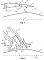
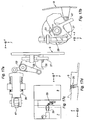
- the axis A of this turbojet engine is indicated in dashed lines on the Figures 1 and 2 , the upstream portion of the turbojet engine to the left of the figures, and the downstream portion to the right of these figures.
- the fixed internal structure 1 can technically be formed of composite material, and may have acoustic absorption characteristics intended to minimize the noise caused by the flow of cold air into the air stream cold 3.
- This cold air duct 3, substantially annular, is defined on the one hand by the internal fixed structure 1, and on the other hand by the peripheral part of the nacelle, conventionally comprising a thrust reverser device 5.
- such a thrust reverser device is movable between the configuration visible to the figure 1 , called “direct jet", in which the flow of cold air D circulates inside the vein 3 from upstream to downstream of the nacelle, and the visible configuration of the figure 2 so-called “reverse jet” in which the cold air flow I is rejected upstream of the nacelle, so as to exert a counter-thrust force.
- the "direct jet” configuration corresponds to the take-off and cruise flight situations of the aircraft, and the "reverse jet” situation corresponds to the landing situation of the aircraft, in which the aim is to minimize the distance braking.
- the thrust reverser device 5 is of the twin-door type.
- the upstream door 7 extends between the front frame 15, which is a fixed part of the nacelle, and the downstream door 9.
- This downstream door 9 extends between the upstream door 7 and the rear edge 17 of the nacelle.
- downstream door 9 comprises, on its outer upstream edge, a skin that advances to the outer downstream edge of the upstream door 7, thus ensuring the aerodynamic continuity of the outside of the nacelle.
- the two doors 7 and 9 are opened by pivoting them about their respective axes 11 and 13, so as to bring them to the end. to their visible position at the figure 2 .
- Another portion I2 of the cold air flow passes between the downstream edge 23 of the upstream door 7 and the fixed internal structure 1 of the nacelle 1, and is deflected by the downstream door 9 which completely closes the cold air vein 3.
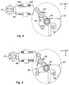
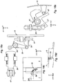
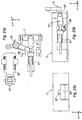
- the locking system 25 comprises a hook 27 pivotally mounted on the upstream door 7 about a Z direction axis.
- a locking latch 29 is itself pivotally mounted on the upstream door 7 about another axis Z direction.
- This locking latch 29 comprises a tail 31 terminated by a roller 33, this tail itself being capable of cooperating with a tail 35 of the hook 27, so as to prevent rotation of the latter.
- the latch 29 further comprises a head 37 capable of being pushed by a slider 39, slidably mounted on the underside of the upstream door 7, and connected by a hinge 40 to the end of the rod 41 of a hydraulic cylinder or electric 43, which cylinder makes it possible to move the upstream door 7 from its closed position ("direct jet” - figure 1 ) to its open position ("inverted jet” - figure 2 ).
- downstream door 9 is connected to the upstream door 7 by a pair of connecting rods 45a, 45b, arranged so that the opening / closing of the upstream door causes the opening / closing of the downstream door 9.
- the hook 27 cooperates with a pin 47 extending substantially in the direction Z, integral with the sliding cover, preferably surrounded by a roller 49.
- Spiral springs 51, 53 respectively centered on the axes of rotation of the hook 27 and the latch 29, tend to rotate respectively these two members in a clockwise and anti-clockwise manner.
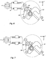
- Belleville washers 54a, 54b provide elasticity and damping of the movements of the slider 39 relative to the upstream door 7. Without action of the jack 41 on the slider 39, the springs 54a and 54b are advantageously adjusted so that the spring 54b keeps the slide 39 away from the roller 37, to preserve the lock in case of rupture of a cylinder 41.
- the two upstream and downstream gates 9 connected to each other by the connecting rods 45a and 45b can pivot towards their open position shown in FIG. figure 2 , to return the cold air flow to the front of the nacelle, and thus perform the thrust reversal function.
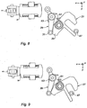
- the pin 47 eventually abuts against the hook 27 and pivots the latter clockwise, against the spiral spring ( Figures 8 and 9 ), until the tail 35 of the hook 27 passes through the tail 31 of the latch 29, allowing the latch to return to its initial position ( figure 10 ): it is then in the configuration where the hook 27 blocks any relative movement of the upstream and downstream doors 7 9, thus achieving a safety lock completely independent of other locking systems.
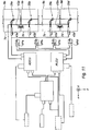
- each upstream door 7a, 7b, 7c, 7d is actuated by a respective cylinder 43a, 43b, 43c, 43d, which is capable of acting on a respective locking system 25a, 25b, 25c, 25d, arranged between the upstream doors 7a, 7b, 7c, 7d and downstream 9a, 9b, 9c, 9d, according to the explanation just given.
- these locking systems 25a, 25b, 25c, 25d are independent of two other locking systems, to guard against inadvertent opening of the twin doors.
- synchronization locks VSa and VSb are arranged between two adjacent upstream gates, on the one hand 7a, 7b and on the other hand 7c, 7d, preventing the opening of an upstream door as long as its adjacent upstream door n is itself not open: such a system is known per se, in particular from the patent FR 2 823 259 it will not be described in more detail here.
- control unit ADCU Actuator Directional Control Unit
- cylinders 43a, 43b, 43c, 43d is totally independent of the PLCU control unit, so that the three locking systems which have just been described (25, VP, VS) are completely independent of each other, thus guaranteeing the perfect safety of the locking of the doors of the thrust reverser in the "direct jet" position.
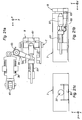
- the rotation of the hook 27 and the latch 29 is performed about axes substantially parallel to the axes of rotation 11 and 13 of the upstream and downstream doors 9 and 9, while in the previous embodiment, the axes of rotation of the hook 27 and the latch 29 were substantially perpendicular to the axes of rotation 11 and 13 of the doors 7 and 9, and the axis A of the nacelle.
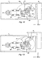
- an extension 41 of the rod of the cylinder 43 has the effect of pushing on the head 37 of the latch 29, against the spiral spring 53, thus causing a rotation on the latch in the clockwise direction and releasing at the same the tail 35 of the hook 27, which can then pivot under the action of the spiral spring 51 in the counterclockwise direction, thus releasing the pin 47 secured to the downstream door 9 (see Figures 12 and 13 ).
- the tail 35 of the hook 27 extends in a direction substantially parallel to the median plane of this hook, that is to say in a direction substantially parallel to the axis A of the nacelle ( direction X).
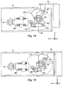
- the thrust exerted by the slider 39 on the head 37 of the latch 29, during the extension of the rod 41 of the jack 43 has the effect of disengaging the tail 31 of the latch 29 from the 35 of the hook 47 (see figures 16 and 17 ), thus releasing the pin 47, thus allowing the opening of the two twin doors 7 and 9.
- the movements of the bolt 27 are substantially in the direction X, that is to say, parallel to the axis A of the nacelle.
- This bolt 27 is capable of moving against the helical spring 51 under the action of the tail 31 of the latch 29, when it is actuated clockwise by the slide 39 mounted at the end of the rod 41 of the cylinder 43.
- This tail 31 may advantageously have a stirrup shape to surround the bolt 27.
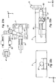
- Figures 20a, 20b, 20c corresponds to the "direct jet" configuration, in which it is desired that the upstream 7 and downstream 9 doors are locked relative to each other.
- the spring 51 is in full extension, so that the downstream end of the bolt 27 protrudes from the downstream edge of the door 7, and enters a keeper 61 (that is to say in a corresponding hole) formed on the upstream edge of the door 9.
- a stirrup 63 pivotally mounted about an axis substantially parallel to the axes of rotation 11 and 13 of the upstream and downstream gates 7 9, tilts about its axis under the action of a spiral spring 65 until it prevents the bolt 27 from coming out of the downstream edge of the upstream door 7.
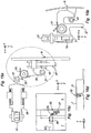
- This embodiment differs from the first three embodiments described above in that the pin 47 is now mounted on the fixed structure of the thrust reverser, in the vicinity of the downstream edge of the downstream gate 9.
- the hook 27 is mounted on the downstream door 9, to the right of the pin 47, pivoting on an axis substantially parallel to the axes 11 and 13 of the two doors.
- a first latch 290 is pivotally mounted on the downstream flap 9, about an axis substantially parallel to the axes of rotation of the two upstream and downstream doors 7 and 9.
- the head 370 of this first latch 290 can be actuated by the slide 39 mounted at the end of the rod 41 of the jack 43.
- the tail 310 of this first latch 290 cooperates with a cable 69 slidably mounted relative to the downstream door 9, and extending to a second latch 29, pivotally mounted about an axis substantially parallel to the axes 11 and 13 of the downstream door 9, against a spiral spring 53.
- the head 37 of this latch 29 cooperates with the cable 69, and the tail 31 of the latch 29 cooperates with a tail 35 of the hook 27, similarly to what has been exposed for the previous embodiments.
- the slider 39 exerts no effort on the head 370 of the first latch 290, so that the tail 31 of the second latch 29 blocks the tail 35 of the lock 27, preventing the latter to pivot, and therefore to disengage the pin 47 secured to the fixed structure of the nacelle: the downstream door 9, and thereby the upstream door 7 (through rods 45a and 45b) can not s 'open.
- the figures 29 show the hook 27 abutting against the pin 47, during an attempt to unintentional opening.
- the present invention provides a locking system of the two twin doors which is totally independent of other locking systems (primary lock and synchronized lock), without it being necessary to provide no additional specific control means.
Landscapes
- Engineering & Computer Science (AREA)
- Chemical & Material Sciences (AREA)
- Combustion & Propulsion (AREA)
- Mechanical Engineering (AREA)
- General Engineering & Computer Science (AREA)
- Power-Operated Mechanisms For Wings (AREA)
- Lock And Its Accessories (AREA)
- Wind Motors (AREA)
- Structures Of Non-Positive Displacement Pumps (AREA)
Description
La présente demande de brevet se rapporte à un inverseur de poussée à portes jumelles.The present patent application relates to a twin-door thrust reverser.
Un inverseur de poussée selon la technique antérieure est connu dans le document
On connaît de la technique antérieure, et notamment de la demande de brevet
Un tel inverseur de poussée permet un grand débit de fuite de l'air froid circulant à l'intérieur de la nacelle, et donc un freinage d'autant plus efficace de l'aéronef à l'atterrissage.Such a thrust reverser allows a large leak rate of the cold air circulating inside the nacelle, and thus braking all the more effective the aircraft landing.
Dans un tel inverseur de poussée, on doit prévoir un certain nombre de verrous assurant une redondance afin de supprimer tout risque d'ouverture intempestive des portes.In such a thrust reverser, there must be a number of locks providing redundancy to eliminate any risk of inadvertent opening of the doors.
Plus précisément, pour respecter les règles de sécurité en vigueur, trois systèmes de verrouillage indépendants doivent être prévus pour chaque porte amont et aval de chaque paire de portes jumelles.More precisely, to respect the safety rules in force, three independent locking systems must be provided for each upstream and downstream door of each pair of twin doors.
Un premier système de verrouillage comprend un verrou solidaire du cadre avant de l'inverseur de poussée, et coopérant avec la porte amont de la paire de portes jumelles.A first locking system comprises a latch secured to the front frame of the thrust reverser, and cooperating with the upstream door of the pair of twin doors.
La porte aval étant reliée par une paire de bielles à la porte amont, ce premier système de verrouillage assure aussi le verrouillage de la porte aval.The downstream door being connected by a pair of connecting rods to the upstream door, this first locking system also ensures the locking of the downstream door.
Un deuxième système de verrouillage comprend un système de synchronisation de l'ouverture de portes adjacentes, tel que celui divulgué par la demande de brevet
Un troisième système de verrouillage coopère directement avec le vérin d'actionnement de la porte amont.A third locking system cooperates directly with the actuating cylinder of the upstream door.
Dans un tel agencement, il y a donc deux systèmes de verrouillage commandés par paire de porte jumelles : le premier et le troisième systèmes susmentionnés ; seul le deuxième système de verrouillage est passif, et ne nécessite donc aucun moyen de commande.In such an arrangement, there are therefore two twin door pair-controlled locking systems: the first and third aforementioned systems; only the second locking system is passive, and therefore requires no control means.
Ainsi, pour un inverseur de poussée à portes jumelles comprenant typiquement quatre paires de portes jumelles, il faut prévoir 8 verrous commandés, ce qui est lourd, complexe et coûteux tant à l'installation qu'à la maintenance.Thus, for a twin-door thrust reverser typically comprising four pairs of twin doors, 8 locks must be provided. ordered, which is cumbersome, complex and costly for both installation and maintenance.
La présente invention a ainsi notamment pour but d'apporter une simplification des moyens de verrouillage d'un tel inverseur de poussée.The present invention is thus particularly intended to provide a simplification of the locking means of such a thrust reverser.
On atteint ce but de l'invention avec un inverseur de poussée pour nacelle de turboréacteur d'aéronef, comprenant :
- au moins une paire de portes jumelles comprenant une porte amont, une porte aval reliée par au moins une bielle à la porte amont, et
- au moins un vérin d'actionnement de la porte amont, entre une position « jet direct » dans laquelle ces deux portes sont fermées, et une position « jet inversé » dans laquelle ces deux portes sont ouvertes et aptes à défléchir au moins une partie du flux d'air froid susceptible de circuler à l'intérieur de la nacelle,
- at least one pair of twin doors comprising an upstream door, a downstream door connected by at least one connecting rod to the upstream door, and
- at least one actuating cylinder of the upstream door, between a "direct jet" position in which these two doors are closed, and an "inverted jet" position in which these two doors are open and able to deflect at least part of the cold air flow likely to circulate inside the nacelle,
Le verrouillage des portes amont et aval entre elles constitue un système de verrouillage indépendant des premier et deuxième systèmes de verrouillage susmentionnés, ne nécessitant donc aucun moyen de commande spécifique puisque ce sont les seuls mouvements du vérin à l'ouverture et à la fermeture des portes qui permettent de réaliser leur verrouillage/déverrouillage.The locking of the upstream and downstream doors between them constitutes a locking system independent of the first and second locking systems mentioned above, thus requiring no specific control means since they are the only movements of the cylinder when opening and closing the doors. which allow to realize their locking / unlocking.
On obtient de la sorte trois systèmes de verrouillage indépendants pour la paire de portes jumelles, ne comprenant qu'un seul verrou commandé : celui du premier système de verrouillage susmentionné.In this way, three independent locking systems are obtained for the pair of twin doors, comprising only one controlled lock: that of the first locking system mentioned above.
Ainsi, pour un inverseur de poussée comprenant quatre paires de portes jumelles, seuls quatre verrous commandés sont nécessaires, ce qui apporte un allègement, une simplification et une réduction des coûts tout à fait considérables.Thus, for a thrust reverser comprising four pairs of twin doors, only four locks ordered are needed, which provides a relief, simplification and a reduction of costs quite considerable.
Suivant d'autres caractéristiques optionnelles de l'inverseur de poussée selon l'invention :
- lesdits moyens de verrouillage/déverrouillage comprennent :
- - un crochet monté pivotant sur ladite porte amont, entre une position de verrouillage d'un pion solidaire de ladite porte aval, et une position de déverrouillage de ce pion,
- - des moyens de rappel élastique dudit crochet vers sa position de verrouillage,
- - un loquet monté pivotant sur ladite porte amont entre une position de blocage dans laquelle il maintient ledit crochet dans sa position de verrouillage, et une position de déblocage, dans laquelle il autorise le passage dudit crochet de sa position de verrouillage à sa position de déverrouillage,
- - des moyens de rappel élastique dudit loquet vers sa position de blocage,
- - ledit vérin et ledit loquet étant agencés l'un par rapport à l'autre de sorte qu'une extension dudit vérin fasse pivoter ledit loquet vers sa position de déblocage ;
- ledit crochet et ledit loquet sont montés pivotants autour d'axes sensiblement perpendiculaires aux axes de rotation des portes amont et aval et à l'axe de la nacelle ;
- ledit crochet et ledit loquet sont montés pivotants autour d'axes sensiblement parallèles aux axes de rotation des portes amont et aval ;
- ledit crochet est monté pivotant autour d'un axe sensiblement parallèle à l'axe de la nacelle, et ledit loquet est monté pivotant autour d'un axe sensiblement perpendiculaire aux axes de rotation des portes amont et aval et à l'axe de la nacelle;
- lesdits moyens de verrouillage/déverrouillage comprennent :
- - un pêne monté coulissant dans ladite porte amont, entre une position de verrouillage d'une gâche formée dans ladite porte aval, et une position de déverrouillage de cette gâche,
- - des moyens de rappel élastique dudit pêne vers sa position de verrouillage,
- - un loquet monté pivotant sur ladite porte amont et coopérant avec ledit pêne de sorte qu'une rotation de ce loquet ait pour effet de faire coulisser ce pêne,
- - ledit vérin et ledit loquet étant agencés l'un par rapport à l'autre de sorte qu'une extension dudit vérin fasse pivoter ladite gâchette dans un sens provoquant le coulissement dudit pêne vers sa position de déverrouillage ;
- lesdits moyens de verrouillage/déverrouillage comprennent en outre un étrier monté pivotant sur ladite porte amont autour d'un axe sensiblement parallèle aux axes de rotation desdites portes amont et aval, et des moyens élastiques rappelant cet étrier vers une position dans laquelle il assure le maintien dudit pêne dans sa position de déverrouillage ;
- ladite porte aval comprend un organe d'appui, apte à faire pivoter ledit étrier à l'encontre desdits moyens élastiques.
- lesdits moyens de verrouillage/déverrouillage comprennent :
- - un crochet monté pivotant sur ladite porte aval, entre une position de verrouillage d'un pion solidaire de la structure fixe dudit inverseur, et une position de déverrouillage de ce pion,
- - des moyens de rappel élastique dudit crochet vers sa position de verrouillage,
- - un loquet monté pivotant sur ladite porte aval entre une position de blocage dans laquelle il maintient ledit crochet dans sa position de verrouillage, et une position de déblocage, dans laquelle il autorise le passage dudit crochet de sa position de verrouillage à sa position de déverrouillage,
- - des moyens de rappel élastique dudit loquet vers sa position de blocage,
- - un câble dont une extrémité est montée coulissante sur ladite porte amont, et dont l'autre extrémité est reliée audit loquet, de sorte qu'une extension dudit vérin provoque le coulissement dudit câble par rapport à ladite porte amont, et ainsi la rotation dudit loquet vers sa position de déblocage.
- said locking / unlocking means comprise:
- a hook pivotally mounted on said upstream door, between a locking position of a peg integral with said downstream door, and an unlocking position of this peg,
- - Elastic return means of said hook to its locking position,
- a latch pivotally mounted on said upstream door between a locking position in which it holds said hook in its locking position, and an unlocking position, in which it allows the passage of said hook from its locking position to its unlocking position; ,
- - Elastic return means of said latch to its locking position,
- - said cylinder and said latch being arranged relative to each other so that an extension of said cylinder rotates said latch to its unlocking position;
- said hook and said latch are pivotally mounted about axes substantially perpendicular to the axes of rotation of the upstream and downstream doors and the axis of the nacelle;
- said hook and said latch are pivotally mounted about axes substantially parallel to the axes of rotation of the upstream and downstream doors;
- said hook is pivotally mounted about an axis substantially parallel to the axis of the nacelle, and said latch is pivotally mounted about an axis substantially perpendicular to the axes of rotation of the upstream and downstream gates and the axis of the nacelle ;
- said locking / unlocking means comprise:
- a bolt slidably mounted in said upstream door, between a locking position of a striker formed in said downstream door, and an unlocking position of this striker,
- - Elastic return means of said bolt to its locking position,
- - A latch pivotally mounted on said upstream door and cooperating with said bolt so that a rotation of the latch has the effect of sliding the bolt,
- - said cylinder and said latch being arranged relative to each other so that an extension of said cylinder rotates said trigger in a direction causing the sliding of said bolt to its unlocked position;
- said locking / unlocking means further comprise a yoke pivotally mounted on said upstream door about an axis substantially parallel to the axes of rotation of said upstream and downstream gates, and elastic means reminding said stirrup to a position in which it ensures the maintenance of said bolt in its unlocking position;
- said downstream door comprises a support member, able to rotate said stirrup against said elastic means.
- said locking / unlocking means comprise:
- a hook pivotally mounted on said downstream door, between a locking position of a pin integral with the fixed structure of said inverter, and an unlocking position of this pin,
- - Elastic return means of said hook to its locking position,
- a latch pivotally mounted on said downstream door between a locking position in which it holds said hook in its locking position, and an unlocking position, in which it allows the passage of said hook from its locking position to its unlocking position; ,
- - Elastic return means of said latch to its locking position,
- a cable whose one end is slidably mounted on said upstream door, and the other end of which is connected to said latch, so that an extension of said jack causes said cable to slide relative to said upstream door, and thus the rotation of said latch towards its release position.
La présente invention se rapporte également à une nacelle équipée d'un inverseur de poussée conforme à ce qui précède.The present invention also relates to a nacelle equipped with a thrust reverser according to the above.
D'autres caractéristiques et avantages de la présente invention apparaîtront à la lecture de la description qui va suivre, et à l'examen des figures ci-annexées, dans lesquelles :
- la
figure 1 représente de manière schématique un inverseur à portes jumelles dans une configuration « jet direct », - la
figure 2 représente cet inverseur en configuration «jet inversé », - la
figure 3 représente une vue d'ensemble de deux portes jumelles munies d'un système de verrouillage conforme à un premier mode de réalisation de l'invention, - les
figures 4 à 10 représentent ce système de verrouillage dans ses différentes positions de fonctionnement, - la
figure 11 est un schéma de principe du circuit d'actionnement de quatre portes jumelles d'un inverseur de poussée, un dispositif de verrouillage conforme à ce qui précède étant disposé entre les portes de chaque paire de portes jumelles, - les
figures 12 à 15 illustrent un deuxième système de verrouillage selon l'invention, dans ses différentes positions de fonctionnement, - les
figures 16a, 16b, 16c, 16d illustrent un troisième mode de réalisation du système de verrouillage selon l'invention, représenté sous différents angles de vue, - les
figures 17a à 17d ,18a à18d ,19a à 19d , et20a à 20c illustrent ce même système de verrouillage dans ses différentes positions de fonctionnement, - les
figures 21a, 21b, 21c illustrent un quatrième mode de réalisation du système de verrouillage selon l'invention, représenté selon différents angles de vue, - les
figures 22a, 22b, 22c ;23a, 23b, 23c ;24a, 24b, 24c et 25a, 25b, 25c illustrent ce système de verrouillage dans ses différentes positions de fonctionnement, - la
figure 26 est une figure analogue à lafigure 3 , illustrant un cinquième mode de réalisation d'un système de verrouillage selon l'invention, - la
figure 27 représente ce système de verrouillage dans sa partie qui se trouve dans la porte amont, et - les
figures 28 à 33 représentent ce système de verrouillage dans la zone qui se trouve dans la partie aval, dans différentes positions de fonctionnement.
- the
figure 1 schematically represents a twin-gate inverter in a "direct jet" configuration, - the
figure 2 represents this inverter in "reverse jet" configuration, - the
figure 3 represents an overview of two twin doors provided with a locking system according to a first embodiment of the invention, - the
Figures 4 to 10 represent this locking system in its different operating positions, - the
figure 11 is a block diagram of the actuation circuit of four twin doors of a thrust reverser, a locking device according to the above being disposed between the doors of each pair of twin doors, - the
Figures 12 to 15 illustrate a second locking system according to the invention, in its different operating positions, - the
Figures 16a, 16b, 16c, 16d illustrate a third embodiment of the locking system according to the invention, represented from different angles of view, - the
Figures 17a to 17d ,18a to 18d ,19a to 19d , and20a to 20c illustrate this same locking system in its different operating positions, - the
Figures 21a, 21b, 21c illustrate a fourth embodiment of the locking system according to the invention, represented according to different angles of view, - the
Figures 22a, 22b, 22c ;23a, 23b, 23c ;24a, 24b, 24c and25a, 25b, 25c illustrate this locking system in its different operating positions, - the
figure 26 is a figure similar to thefigure 3 , illustrating a fifth embodiment of a locking system according to the invention, - the
figure 27 represents this locking system in its part which is in the upstream door, and - the
Figures 28 to 33 represent this locking system in the area which is in the downstream part, in different operating positions.
Sur l'ensemble de ces figures, des références identiques ou analogues désignent des organes ou ensembles d'organes identiques ou analogues.In all of these figures, identical or similar references designate members or sets of identical or similar members.
On se reporte à la
L'axe A de ce turboréacteur est indiqué en pointillé sur les
Comme cela est connu en soi, la structure interne fixe 1 peut techniquement être formée en matériau composite, et peut présenter des caractéristiques d'absorption acoustique destinées à minimiser le bruit provoqué par la circulation du flux d'air froid dans la veine d'air froid 3.As is known per se, the fixed
Cette veine d'air froid 3, sensiblement annulaire, est définie d'une part par la structure fixe interne 1, et d'autre part par la partie périphérique de la nacelle, comportant classiquement un dispositif d'inversion de poussée 5.This
Comme cela est connu en soi, un tel dispositif d'inversion de poussée est mobile entre la configuration visible à la
La configuration de « jet direct » correspond aux situations de décollage et de vol de croisière de l'aéronef, et la situation de « jet inversé » correspond à la situation d'atterrissage de l'aéronef, dans laquelle on cherche à minimiser la distance de freinage.The "direct jet" configuration corresponds to the take-off and cruise flight situations of the aircraft, and the "reverse jet" situation corresponds to the landing situation of the aircraft, in which the aim is to minimize the distance braking.
Plus particulièrement, dans le cadre de la présente invention, le dispositif d'inversion de poussée 5 est du type à portes jumelles.More particularly, in the context of the present invention, the
Ceci signifie que la déflexion du flux d'air froid vers l'amont de la nacelle est obtenue au moyen de deux portes, respectivement amont 7 et aval 9, articulées autour d'axes de rotation respectifs 12 et 13.This means that the deflection of the cold air flow upstream of the nacelle is obtained by means of two doors, respectively upstream 7 and downstream 9, hinged about respective axes of
Il faut bien entendu comprendre que plusieurs paires de telles portes jumelles peuvent être prévues à la périphérie de la nacelle, une seule telle paire étant toutefois représentée sur les figures ci-annexées dans un souci de simplification.It should of course be understood that several pairs of such twin doors can be provided on the periphery of the nacelle, but only one such pair is shown in the figures appended hereto for the sake of simplification.
La porte amont 7 s'étend entre le cadre avant 15, qui est une partie fixe de la nacelle, et la porte aval 9.The
Cette porte aval 9 s'étend entre la porte amont 7 et le bord arrière 17 de la nacelle.This
Dans la configuration de la
Il est à noter que la porte aval 9 comporte, sur son bord amont extérieur, une peau qui avance jusqu'au bord aval extérieur de la porte amont 7, assurant ainsi la continuité aérodynamique de l'extérieur de la nacelle.It should be noted that the
Lorsque l'on souhaite inverser la poussée de la nacelle, et donc passer en configuration « jet inversé », on ouvre les deux portes 7 et 9 en les faisant pivoter autour de leurs axes respectifs 11 et 13, de manière à les amener jusqu'à leur position visible à la
Dans cette configuration, une partie I1 du flux d'air froid circulant à l'intérieur de la veine 3 est défléchie vers l'amont de la nacelle par la porte amont 7.In this configuration, a part I1 of the cold air flow circulating inside the
Une autre partie I2 du flux d'air froid passe entre le bord aval 23 de la porte amont 7 et la structure interne fixe 1 de la nacelle 1, puis est défléchie par la porte aval 9 qui elle obture complètement la veine d'air froid 3.Another portion I2 of the cold air flow passes between the
Dans ce qui suit, on va décrire un système de verrouillage des portes amont 7 et aval 9 qui se trouve dans la zone Z indiquée à la
Pour effectuer cette description, une utilisera les directions d'un trièdre XYZ, dans lequel la direction X est sensiblement parallèle à l'axe A de la nacelle, Y est sensiblement parallèle aux axes d'articulation 11,13 des portes amont 7 et aval 9, et Z est perpendiculaire aux directions X et Y.To carry out this description, one will use the directions of a XYZ trihedron, in which the direction X is substantially parallel to the axis A of the nacelle, Y is substantially parallel to the hinge axes 11, 13 of the upstream and
En se reportant à la
Un loquet de blocage 29 est lui-même monté pivotant sur la porte amont 7 autour d'un autre axe de direction Z.A locking
Ce loquet de blocage 29 comporte une queue 31 terminée par un galet 33, cette queue étant elle-même susceptible de coopérer avec une queue 35 du crochet 27, de manière à empêcher la rotation de ce dernier.This locking
Le loquet 29 comporte en outre une tête 37 susceptible d'être poussée par un coulisseau 39, monté coulissant sur l'intrados de la porte amont 7, et relié par une articulation 40 à l'extrémité de la tige 41 d'un vérin hydraulique ou électrique 43, lequel vérin permet de faire passer la porte amont 7 de sa position fermée (« jet direct » -
A noter que la porte aval 9 est reliée à la porte amont 7 par une paire de bielles 45a, 45b, agencée de sorte que l'ouverture/fermeture de la porte amont entraîne l'ouverture/fermeture de la porte aval 9.Note that the
Le crochet 27 coopère avec un pion 47 s'étendant sensiblement selon la direction Z, solidaire du capot coulissant, entouré de préférence d'un galet 49.The
Des ressorts spirales 51, 53, centrés respectivement sur les axes de rotation du crochet 27 et du loquet 29, ont tendance à faire pivoter respectivement ces deux organes dans des sens horaire et anti horaire.Spiral springs 51, 53, respectively centered on the axes of rotation of the
Des rondelles Belleville 54a, 54b assurent une élasticité et un amortissement des mouvements du coulisseau 39 par rapport à la porte amont 7. Sans action du vérin 41 sur le coulisseau 39, les ressorts 54a et 54b sont avantageusement réglés afin que le ressort 54b garde le coulisseau 39 éloigné du galet 37, afin de préserver le verrouillage en cas de rupture d'un vérin 41.
Le mode de fonctionnement du système de verrouillage qui vient d'être décrit va à présent être explicité à la lumière des
Lorsque l'on se trouve en configuration « jet direct », le crochet 27 est fermé sur le pion 47, comme cela est visible à la
Lorsque l'on souhaite passer en configuration «jet inversé » (
Ce faisant, comme cela est visible à la
Ainsi, comme cela est visible à la
Ainsi, sous l'effet de l'extension de la tige 41 du vérin 43, les deux portes amont 7 et aval 9 reliées entre elles par les bielles 45a et 45b peuvent pivoter vers leur position d'ouverture représentée à la
Lorsque l'on souhaite alors retourner vers la positon « jet direct » (
Ce faisant, le pion 47 finit par buter contre le crochet 27 et fait pivoter ce dernier dans le sens horaire, à l'encontre du ressort spirale (
En se reportant à la
Comme on peut le voir sur cette
Comme cela a été mentionné plus haut, ces systèmes de verrouillage 25a, 25b, 25c, 25d sont indépendants de deux autres systèmes de verrouillage, permettant de se prémunir de toute ouverture intempestive des portes jumelles.As mentioned above, these locking
Pour chaque paire de portes jumelles, il y a en effet d'une part un système de verrouillage dit « primaire » VPa, VPb, VPc, VPd, agissant directement sur les portes amont 7a, 7b, 7c, 7d, commandées par une unité de contrôle spécifique PLCU (« Primary Lock Control Unit » : unité de commande des verrous primaires »).For each pair of twin doors, there is on the one hand a so-called "primary" locking system VPa, VPb, VPc, VPd, acting directly on the
Par ailleurs, des verrous de synchronisation VSa et VSb sont disposés entre deux portes amont adjacentes, d'une part 7a, 7b et d'autre part 7c, 7d, empêchant l'ouverture d'une porte amont tant que sa porte amont adjacente n'est elle-même pas ouverte : un tel système est connu en soi notamment du brevet
Comme on peut le voir à la
On notera par ailleurs que les différentes positions axiales de ces trois systèmes de verrouillage offrent un maximum de sécurité vis-à-vis d'accidents pouvant survenir à l'intérieur de la nacelle, tels qu'une rupture de disque du moteur (« rotor burst »).Note also that the different axial positions of these three locking systems provide maximum safety vis-à-vis accidents that can occur inside the nacelle, such as a disk rupture of the engine ("rotor burst ").
On se reporte à présent aux
Comme on pourra le comprendre en voyant le système d'axe XYZ représenté sur ces figures, le pivotement du crochet 27 et du loquet 29 s'effectue à présent autour d'axes parallèles à la direction Y.As will be understood by viewing the XYZ axis system shown in these figures, the pivoting of
En d'autres termes, dans le présent mode de réalisation, la rotation du crochet 27 et du loquet 29 s'effectue autour d'axes sensiblement parallèles aux axes de rotation 11 et 13 des portes amont 7 et aval 9, alors que dans le mode de réalisation précédent, les axes de rotation du crochet 27 et du loquet 29 étaient sensiblement perpendiculaires aux axes de rotation 11 et 13 des portes 7 et 9, et à l'axe A de la nacelle.In other words, in the present embodiment, the rotation of the
Comme dans le mode de réalisation précédent, une extension 41 de la tige du vérin 43 a pour effet de pousser sur la tête 37 du loquet 29, à l'encontre du ressort spirale 53, entraînant ainsi une rotation sur le loquet dans le sens horaire et libérant par la même la queue 35 du crochet 27, lequel peut alors pivoter sous l'action du ressort spirale 51 dans le sens anti-horaire, libérant ainsi le pion 47 solidaire de la porte aval 9 (voir
Lorsque la tige 41 du vérin 43 se rétracte, il provoque donc la refermeture de la porte aval 9 sur la porte amont 7 par le truchement des bielles 45a, et 45b, et le pion 47 vient se reloger à l'intérieur du crochet 27, entraînant ainsi le pivotement de celui-ci dans le sens horaire à l'encontre du ressort spirale 51, jusqu'à ce que la queue 35 de ce crochet passe outre la queue 31 de ce loquet 29 (voir
Le mode de réalisation des
Dans le cadre de cet agencement particulier, la queue 35 du crochet 27 s'étend selon une direction sensiblement parallèle au plan médian de ce crochet, c'est-à-dire selon une direction sensiblement parallèle à l'axe A de la nacelle (direction X).In the context of this particular arrangement, the
Comme dans les deux modes de réalisation précédents, la poussée exercée par le coulisseau 39 sur la tête 37 du loquet 29, lors de l'extension de la tige 41 du vérin 43, a pour effet de dégager la queue 31 du loquet 29 de celle 35 du crochet 47 (voir
Lorsque la tige 41 du vérin 43 se rétracte (voir
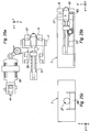
On se reporte à présent aux
Comme on peut le voir, dans ce mode de réalisation, on prévoit un pêne 27 monté coulissant à l'intérieur de la porte amont 7, à l'encontre d'un ressort hélicoïdal 51.As can be seen, in this embodiment, there is provided a
Les déplacements du pêne 27 s'effectuent sensiblement selon la direction X, c'est-à-dire parallèlement à l'axe A de la nacelle.The movements of the
Ce pêne 27 est susceptible de se mouvoir à l'encontre du ressort hélicoïdal 51 sous l'action de la queue 31 du loquet 29, lorsque celui-ci est actionné dans le sens horaire par le coulisseau 39 monté à l'extrémité de la tige 41 du vérin 43. Cette queue 31 pourra avantageusement présenter une forme en étrier pour entourer le pêne 27.This
La configuration des
Dans cette configuration, le ressort 51 est en extension complète, de sorte que l'extrémité aval du pêne 27 dépasse du bord aval de la porte 7, et pénètre dans une gâche 61 (c'est-à-dire dans un orifice correspondant) formée sur le bord amont de la porte 9.In this configuration, the
De la sorte, le pêne 27, qui travaille en cisaillement, empêche tout mouvement relatif du bord amont de la porte aval 9 par rapport au bord aval de la porte amont 7.In this way, the
Lorsque l'on souhaite procéder à l'ouverture sur des portes jumelles, on agit donc sur le vérin 43 de manière à procéder à l'extension de sa tige 41, ce qui a pour effet de faire pivoter le loquet 29 dans le sens horaire, et ainsi de translater le pêne 27, de sorte qu'il comprime le ressort hélicoïdal 51, et ne dépasse ainsi plus du bord aval de la porte amont 7 : on libère ainsi la gâche 61, de sorte que le bord amont de la porte aval 9 n'est plus verrouillé par rapport au bord aval de la porte amont 7 (voir
Lors de cette ouverture, un étrier 63, monté pivotant autour d'un axe sensiblement parallèle aux axes de rotation 11 et 13 des portes amont 7 et aval 9, bascule autour de son axe sous l'action d'un ressort spirale 65 jusqu'à ce qu'il vienne empêcher que le pêne 27 ne ressorte du bord aval de la porte amont 7.During this opening, a
Lorsque l'on souhaite refermer les deux portes 7 et 9 de l'inverseur de poussée, on rétracte la tige 41 du vérin 43, comme cela est visible sur la
Lorsque le pêne 27 a retrouvé cette position, il assure de nouveau le blocage relatif des portes amont 7 et aval 9, et donc le parfait maintien de l'inverseur de poussée dans sa configuration « jet direct » (voir
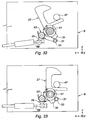
On se reporte à présent aux
Ce mode de réalisation diffère des trois premiers modes de réalisation décrits précédemment en ceci que le pion 47 est à présent monté sur la structure fixe de l'inverseur de poussée, au voisinage du bord aval de la porte aval 9.This embodiment differs from the first three embodiments described above in that the
Le crochet 27 est quant à lui monté sur la porte aval 9, au droit du pion 47, pivotant sur un axe sensiblement parallèle aux axes 11 et 13 des deux portes.The
Comme cela et visible à la
La tête 370 de ce premier loquet 290 est susceptible d'être actionnée par le coulisseau 39 monté à l'extrémité de la tige 41 du vérin 43.The
La queue 310 de ce premier loquet 290 coopère avec un câble 69 monté coulissant par rapport à la porte aval 9, et s'étendant jusqu'à un deuxième loquet 29, monté pivotant autour d'un axe sensiblement parallèle aux axes 11 et 13 de la porte aval 9, à l'encontre d'un ressort spirale 53.The
La tête 37 de ce loquet 29 coopère avec le câble 69, et la queue 31 de ce loquet 29 coopère avec une queue 35 du crochet 27, de manière analogue à ce qui a été exposé pour les modes de réalisation précédents.The
Plus précisément, en position de verrouillage des deux portes 7 et 9, le coulisseau 39 n'exerce aucun effort sur la tête 370 du premier loquet 290, de sorte que la queue 31 du deuxième loquet 29 bloque la queue 35 du cochet 27, empêchant ce dernier de pivoter, et donc de se désengager du pion 47 solidaire de la structure fixe de la nacelle : la porte aval 9, et par là-même la porte amont 7 (par le truchement de bielles 45a et 45b) ne peuvent donc s'ouvrir.More specifically, in the locking position of the two
Les
Lorsque l'on souhaite procéder à l'ouverture des portes amont 7 et aval 9, on procède à l'extension de la tige 41 du vérin 43, ce qui a pour effet de déplacer le coulisseau 39 qui vient faire pivoter le premier loquet 290 dans le sens inverse des aiguilles d'une montre.When it is desired to open the upstream and
Ce faisant, un effort de traction est exercé sur le câble 69 par la queue 310 de ce loquet 290.In doing so, a pulling force is exerted on the
Cet effort de traction a pour effet de faire pivoter le deuxième loquet 29 dans le sens des aiguilles d'une montre, et ainsi de libérer la queue 35 du crochet 27, comme cela est visible à la
Lorsque l'on souhaite refermer ces deux portes, on rétracte la tige 41 du vérin 43, ce qui a pour effet de ramener le crochet 7 au contact du pion 47 (voir
Comme l'on peut le comprendre à la lumière de la description qui précède, la présente invention fournit un système de verrouillage des deux portes jumelles qui est totalement indépendant des autres systèmes de verrouillage (verrouillage primaire et verrouillage synchronisé), sans qu'il soit nécessaire de prévoir aucun moyen de commande spécifique supplémentaire.As can be understood from the foregoing description, the present invention provides a locking system of the two twin doors which is totally independent of other locking systems (primary lock and synchronized lock), without it being necessary to provide no additional specific control means.
Comme on l'aura compris à la lumière de la description qui précède, et notamment à l'examen de la
Ainsi, pour un inverseur de poussée comportant quatre paires de portes jumelles comme représenté à la figue 11, seuls quatre verrous VPa, VPb, VPc, VPd nécessitent des moyens de commande, ce qui est extrêmement avantageux en termes de poids, de coût et de facilité de maintenance.Thus, for a thrust reverser comprising four pairs of twin gates as shown in FIG. 11, only four latches VPa, VPb, VPc, VPd require control means, which is extremely advantageous in terms of weight, cost and reliability. ease of maintenance.
Bien entendu, la présente invention n'est nullement limitée aux modes de réalisation décrits et représentés, fournis à titre de simples exemples.Of course, the present invention is not limited to the embodiments described and shown, provided as simple examples.
Claims (10)
- A thrust reverser for an aircraft turbojet engine nacelle, comprising :- at least one pair of twin doors comprising an upstream door (7), a downstream door (9) connected by at least one connecting rod (45a, 45b) to the upstream door (7), and- at least one actuating cylinder (43) of the upstream door (7) between a « direct jet » position wherein these two doors are closed, and a « reverse jet » position wherein these two doors are open and adapted to deflect at least a portion (I) of the cold air flow likely to circulate inside the nacelle, and- means (25) for locking/unlocking said upstream and downstream doors together under the sole action of said cylinder (43).
- The thrust reverser according to claim 1, wherein said locking/unlocking means comprise :- a hook (27) pivotally mounted on said upstream door (7), between a locked position of a pin (47) secured to said downstream door (9), and an unlocked position of this pin (47),- means (51) for elastically returning said hook to its locked position,- a latch (29) pivotally mounted on said upstream door (7) between a blocking position wherein it holds said hook (27) in its locked position, and a release position, wherein it allows said hook (27) to switch from its locked position to its unlocked position,- means (53) for elastically returning said latch (29) to its blocking position,- said cylinder (43) and said latch (29) being arranged relative to each other so that an extension of said cylinder (43) makes said latch (29) pivot toward its release position.
- The thrust reverser according to claim 2, wherein said hook (27) and said latch (29) are pivotally mounted about axes substantially perpendicular to the axes of rotation (11, 13) of the upstream (7) and downstream (9) doors and to the axis (A) of the nacelle.
- The thrust reverser according to claim 2, wherein said hook (27) and said latch (29) are pivotally mounted about axes substantially parallel to the axes of rotation (11) of the upstream (7) and downstream (9) doors.
- The thrust reverser according to claim 2, wherein said hook (27) is pivotally mounted about an axis substantially parallel to the axis (A) of the nacelle, and said latch (29) is pivotally mounted about an axis substantially perpendicular to the axes of rotation (11, 13) of the upstream (7) and downstream (9) doors and to the axis (A) of the nacelle.
- The thrust reverser according to claim 1, wherein said locking/unlocking means comprise :- a bolt (27) slidably mounted in said upstream door (7), between a locked position of a striker (61) formed in said downstream door (9), and an unlocked position of this striker (61),- means (51) for elastically returning said bolt (27) to its locked position,- a latch (29) pivotally mounted on said upstream door (7) and cooperating with said bolt (27) so that rotation of this latch (29) has the effect of making this bolt (27) slide,- said cylinder (43) and said latch (29) being arranged relative to each other so that an extension of said cylinder (43) makes said latch (29) pivot in a direction causing said bolt (27) to slide toward its unlocked position.
- The thrust reverser according to claim 6, wherein said locking/unlocking means further comprise a yoke (63) pivotally mounted on said upstream door (7) about an axis substantially parallel to the axes of rotation (11, 13) of said upstream (7) and downstream (9) doors, and elastic means (65) for returning this yoke to a position wherein it ensures maintaining said bolt (27) in its unlocked position.
- The thrust reverser according to claim 7, wherein said downstream door (9) comprises a bearing member (67), adapted to pivot said yoke (63) against said elastic means (65).
- The thrust reverser according to claim 1, wherein said locking/unlocking means comprise :- a hook (27) pivotally mounted on said downstream door (9), between a locked position of a pin (47) secured to the fixed structure of said reverser, and an unlocked position of this pin (47),- means (51) for elastically returning said hook (27) toward its locked position,- a latch (29) pivotally mounted on said downstream door (9) between a blocking position wherein it maintains said hook (27) in its locked position, and a release position, wherein it allows said hook (27) to switch from its locked position to its unlocked position,- means (53) for elastically returning said latch (29) to its blocking position,- a cable (69) having one end slidably mounted on said upstream door (7), and another end connected to said latch (29), so that an extension of said cylinder (43) causes said cable (69) to slide relative to said upstream door (7), and, thus, said latch (29) to rotate toward its release position.
- A nacelle fitted with a thrust reverser in accordance with any one of the preceding claims.
Applications Claiming Priority (2)
| Application Number | Priority Date | Filing Date | Title |
|---|---|---|---|
| FR1103406A FR2982324B1 (en) | 2011-11-09 | 2011-11-09 | PUSH-IN REVERSER WITH TWIN DOORS |
| PCT/FR2012/052409 WO2013068664A1 (en) | 2011-11-09 | 2012-10-22 | Thrust reverser having twin doors |
Publications (2)
| Publication Number | Publication Date |
|---|---|
| EP2780574A1 EP2780574A1 (en) | 2014-09-24 |
| EP2780574B1 true EP2780574B1 (en) | 2016-03-23 |
Family
ID=47191973
Family Applications (1)
| Application Number | Title | Priority Date | Filing Date |
|---|---|---|---|
| EP12787791.8A Not-in-force EP2780574B1 (en) | 2011-11-09 | 2012-10-22 | Thrust reverser having twin doors |
Country Status (8)
| Country | Link |
|---|---|
| US (1) | US20140245716A1 (en) |
| EP (1) | EP2780574B1 (en) |
| CN (1) | CN103917765B (en) |
| BR (1) | BR112014010136A2 (en) |
| CA (1) | CA2851891A1 (en) |
| FR (1) | FR2982324B1 (en) |
| RU (1) | RU2014122759A (en) |
| WO (1) | WO2013068664A1 (en) |
Families Citing this family (8)
| Publication number | Priority date | Publication date | Assignee | Title |
|---|---|---|---|---|
| FR2970521B1 (en) * | 2011-01-17 | 2013-01-04 | Aircelle Sa | THRUST INVERTER FOR AN AIRCRAFT AIRCRAFT WITH LOW NUMBER OF LATCHES |
| FR3019857B1 (en) * | 2014-04-11 | 2020-12-25 | Aircelle Sa | TURBOREACTOR NACELLE THRUST INVERTER INCLUDING COMMON CONTROL FOR MOVABLE COVERS AND VARIABLE TUBE |
| CN106378445A (en) * | 2016-10-08 | 2017-02-08 | 江苏国能合金科技有限公司 | Vehicle frame locking device for amorphous thin ribbon equipment |
| FR3065260B1 (en) * | 2017-04-14 | 2020-10-09 | Safran Aircraft Engines | THRUST INVERTER SYSTEM FOR TURBOREACTOR |
| EP3406859B1 (en) * | 2017-05-22 | 2023-03-01 | Goodrich Actuation Systems Limited | Thrust reverser tertiary locking system |
| US10612491B2 (en) * | 2017-09-25 | 2020-04-07 | Rohr, Inc. | Mounting device with pin actuator |
| US10907577B2 (en) * | 2017-10-23 | 2021-02-02 | Rohr, Inc. | Translating lock for pivot door thrust reverser |
| FR3086007B1 (en) * | 2018-09-18 | 2020-09-04 | Safran Nacelles | TURBOREACTOR NACELLE WITH A GRID THRUST INVERTER INCLUDING A SHUTTER CONTROL SECTOR |
Family Cites Families (7)
| Publication number | Priority date | Publication date | Assignee | Title |
|---|---|---|---|---|
| US3739582A (en) * | 1972-04-13 | 1973-06-19 | Rohr Industries Inc | Thrust reversing apparatus |
| FR2722534B1 (en) * | 1994-07-13 | 1996-08-14 | Hispano Suiza Sa | DOUBLE FLOW TURBOREACTOR DRIVE INVERTER WITH EXTERNAL OBSTACLES |
| FR2754565B1 (en) | 1996-10-10 | 1999-01-08 | Hispano Suiza Sa | PUSH INVERTER WITH CONTROLLED LEAKAGE FLOW DOORS |
| FR2764341B1 (en) * | 1997-06-05 | 1999-07-16 | Hispano Suiza Sa | TURBOSPROCKET DRIVE WITH SCOOPING DOORS ASSOCIATED WITH A MOBILE DEFLECTOR |
| FR2823259B1 (en) | 2001-04-05 | 2003-06-27 | Hispano Suiza Sa | SYNCHRONIZED LOCKING SYSTEM FOR THE DOORS OF A PUSH INVERTER |
| US7146796B2 (en) * | 2003-09-05 | 2006-12-12 | The Nordam Group, Inc. | Nested latch thrust reverser |
| FR2926112A1 (en) * | 2008-01-08 | 2009-07-10 | Aircelle Sa | THRUST INVERTER WITH DOORS FOR TURBOJET ENGINE |
-
2011
- 2011-11-09 FR FR1103406A patent/FR2982324B1/en not_active Expired - Fee Related
-
2012
- 2012-10-22 CN CN201280055100.3A patent/CN103917765B/en not_active Expired - Fee Related
- 2012-10-22 EP EP12787791.8A patent/EP2780574B1/en not_active Not-in-force
- 2012-10-22 BR BR112014010136A patent/BR112014010136A2/en not_active IP Right Cessation
- 2012-10-22 CA CA2851891A patent/CA2851891A1/en not_active Abandoned
- 2012-10-22 RU RU2014122759/06A patent/RU2014122759A/en not_active Application Discontinuation
- 2012-10-22 WO PCT/FR2012/052409 patent/WO2013068664A1/en active Application Filing
-
2014
- 2014-05-09 US US14/273,778 patent/US20140245716A1/en not_active Abandoned
Non-Patent Citations (1)
| Title |
|---|
| None * |
Also Published As
| Publication number | Publication date |
|---|---|
| CN103917765B (en) | 2016-03-30 |
| CA2851891A1 (en) | 2013-05-16 |
| BR112014010136A2 (en) | 2017-04-25 |
| FR2982324B1 (en) | 2013-11-15 |
| EP2780574A1 (en) | 2014-09-24 |
| WO2013068664A1 (en) | 2013-05-16 |
| FR2982324A1 (en) | 2013-05-10 |
| RU2014122759A (en) | 2015-12-20 |
| US20140245716A1 (en) | 2014-09-04 |
| CN103917765A (en) | 2014-07-09 |
Similar Documents
| Publication | Publication Date | Title |
|---|---|---|
| EP2780574B1 (en) | Thrust reverser having twin doors | |
| EP2773861B1 (en) | Cascade-type thrust reverser with one-piece mobile cowl | |
| EP0869272B1 (en) | Thrust reverser which is protected against unlocking by accidental damage | |
| EP1260696B1 (en) | Synchronised latch system for thrust reverser blocker doors | |
| EP1916132B1 (en) | Push handle and lever locking device for a sliding panel, corresponding blocking device and automobile. | |
| CA2824372A1 (en) | Aircraft turbojet engine thrust reverser with a reduced number of latches | |
| EP3581742B1 (en) | Door flush handle and method of operating the same | |
| CA2678308A1 (en) | Jack with integrated locking device | |
| CA2379192C (en) | Thrust reverser door emergency locking system | |
| WO1998014699A1 (en) | Method and devices for closing the doors of a thrust reverser | |
| CA2799361A1 (en) | Thrust reverser having a lockable variable nozzle section | |
| CA2243057A1 (en) | Visible locking thrust reverser | |
| CA2696231A1 (en) | Thrust reverser with a system for braking the actuators | |
| EP2132427A2 (en) | Nacelle for turbojet jet fitted with a single door thrust reverser system | |
| EP3191368B1 (en) | Propulsion unit for an aircraft and method for opening a movable cowl of said propulsion unit | |
| FR3012089A1 (en) | LOCKING DEVICE IN POSITION OF A FOLDING ELEMENT FOR A VEHICLE SEAT | |
| EP1673530B1 (en) | Thrust reverser lock comprising locking device | |
| FR2711187A1 (en) | Bypass turbojet surrounded by a load-withstanding hoop connected to at least one thrust reverser tilting door | |
| EP2178756B1 (en) | Coupling device for connecting the two half-shells of an aircraft engine nacelle, and nacelle equipped with such a device | |
| EP3584157A1 (en) | Method for operating hold doors of aircraft landing gear | |
| CA2681354A1 (en) | Device for varying the cross section of a secondary nozzle associated with a gate reverser and jet smoothing device | |
| WO2015140450A1 (en) | Locking device for a door-type thrust reverser | |
| EP3701137A1 (en) | Thrust reverser with a system for locking and unlocking under load | |
| EP3696088A1 (en) | Turbojet nacelle comprising a locking door and a system for the deployment of the locking door | |
| FR2953491A1 (en) | AIRCRAFT NACELLE INCORPORATING A DEVICE FOR PROTECTING A ACCESS COMPONENT FOR A LATCHING SYSTEM |
Legal Events
| Date | Code | Title | Description |
|---|---|---|---|
| PUAI | Public reference made under article 153(3) epc to a published international application that has entered the european phase |
Free format text: ORIGINAL CODE: 0009012 |
|
| 17P | Request for examination filed |
Effective date: 20140520 |
|
| AK | Designated contracting states |
Kind code of ref document: A1 Designated state(s): AL AT BE BG CH CY CZ DE DK EE ES FI FR GB GR HR HU IE IS IT LI LT LU LV MC MK MT NL NO PL PT RO RS SE SI SK SM TR |
|
| DAX | Request for extension of the european patent (deleted) | ||
| GRAP | Despatch of communication of intention to grant a patent |
Free format text: ORIGINAL CODE: EPIDOSNIGR1 |
|
| INTG | Intention to grant announced |
Effective date: 20150922 |
|
| GRAS | Grant fee paid |
Free format text: ORIGINAL CODE: EPIDOSNIGR3 |
|
| GRAA | (expected) grant |
Free format text: ORIGINAL CODE: 0009210 |
|
| INTG | Intention to grant announced |
Effective date: 20160127 |
|
| AK | Designated contracting states |
Kind code of ref document: B1 Designated state(s): AL AT BE BG CH CY CZ DE DK EE ES FI FR GB GR HR HU IE IS IT LI LT LU LV MC MK MT NL NO PL PT RO RS SE SI SK SM TR |
|
| REG | Reference to a national code |
Ref country code: GB Ref legal event code: FG4D Free format text: NOT ENGLISH |
|
| REG | Reference to a national code |
Ref country code: CH Ref legal event code: EP |
|
| REG | Reference to a national code |
Ref country code: AT Ref legal event code: REF Ref document number: 783418 Country of ref document: AT Kind code of ref document: T Effective date: 20160415 |
|
| REG | Reference to a national code |
Ref country code: IE Ref legal event code: FG4D Free format text: LANGUAGE OF EP DOCUMENT: FRENCH |
|
| REG | Reference to a national code |
Ref country code: DE Ref legal event code: R096 Ref document number: 602012016029 Country of ref document: DE |
|
| REG | Reference to a national code |
Ref country code: LT Ref legal event code: MG4D |
|
| REG | Reference to a national code |
Ref country code: NL Ref legal event code: MP Effective date: 20160323 |
|
| PG25 | Lapsed in a contracting state [announced via postgrant information from national office to epo] |
Ref country code: HR Free format text: LAPSE BECAUSE OF FAILURE TO SUBMIT A TRANSLATION OF THE DESCRIPTION OR TO PAY THE FEE WITHIN THE PRESCRIBED TIME-LIMIT Effective date: 20160323 Ref country code: FI Free format text: LAPSE BECAUSE OF FAILURE TO SUBMIT A TRANSLATION OF THE DESCRIPTION OR TO PAY THE FEE WITHIN THE PRESCRIBED TIME-LIMIT Effective date: 20160323 Ref country code: NO Free format text: LAPSE BECAUSE OF FAILURE TO SUBMIT A TRANSLATION OF THE DESCRIPTION OR TO PAY THE FEE WITHIN THE PRESCRIBED TIME-LIMIT Effective date: 20160623 Ref country code: GR Free format text: LAPSE BECAUSE OF FAILURE TO SUBMIT A TRANSLATION OF THE DESCRIPTION OR TO PAY THE FEE WITHIN THE PRESCRIBED TIME-LIMIT Effective date: 20160624 |
|
| REG | Reference to a national code |
Ref country code: AT Ref legal event code: MK05 Ref document number: 783418 Country of ref document: AT Kind code of ref document: T Effective date: 20160323 |
|
| PG25 | Lapsed in a contracting state [announced via postgrant information from national office to epo] |
Ref country code: NL Free format text: LAPSE BECAUSE OF FAILURE TO SUBMIT A TRANSLATION OF THE DESCRIPTION OR TO PAY THE FEE WITHIN THE PRESCRIBED TIME-LIMIT Effective date: 20160323 Ref country code: LV Free format text: LAPSE BECAUSE OF FAILURE TO SUBMIT A TRANSLATION OF THE DESCRIPTION OR TO PAY THE FEE WITHIN THE PRESCRIBED TIME-LIMIT Effective date: 20160323 Ref country code: RS Free format text: LAPSE BECAUSE OF FAILURE TO SUBMIT A TRANSLATION OF THE DESCRIPTION OR TO PAY THE FEE WITHIN THE PRESCRIBED TIME-LIMIT Effective date: 20160323 Ref country code: LT Free format text: LAPSE BECAUSE OF FAILURE TO SUBMIT A TRANSLATION OF THE DESCRIPTION OR TO PAY THE FEE WITHIN THE PRESCRIBED TIME-LIMIT Effective date: 20160323 Ref country code: SE Free format text: LAPSE BECAUSE OF FAILURE TO SUBMIT A TRANSLATION OF THE DESCRIPTION OR TO PAY THE FEE WITHIN THE PRESCRIBED TIME-LIMIT Effective date: 20160323 |
|
| PG25 | Lapsed in a contracting state [announced via postgrant information from national office to epo] |
Ref country code: EE Free format text: LAPSE BECAUSE OF FAILURE TO SUBMIT A TRANSLATION OF THE DESCRIPTION OR TO PAY THE FEE WITHIN THE PRESCRIBED TIME-LIMIT Effective date: 20160323 Ref country code: IS Free format text: LAPSE BECAUSE OF FAILURE TO SUBMIT A TRANSLATION OF THE DESCRIPTION OR TO PAY THE FEE WITHIN THE PRESCRIBED TIME-LIMIT Effective date: 20160723 Ref country code: PL Free format text: LAPSE BECAUSE OF FAILURE TO SUBMIT A TRANSLATION OF THE DESCRIPTION OR TO PAY THE FEE WITHIN THE PRESCRIBED TIME-LIMIT Effective date: 20160323 |
|
| PG25 | Lapsed in a contracting state [announced via postgrant information from national office to epo] |
Ref country code: PT Free format text: LAPSE BECAUSE OF FAILURE TO SUBMIT A TRANSLATION OF THE DESCRIPTION OR TO PAY THE FEE WITHIN THE PRESCRIBED TIME-LIMIT Effective date: 20160725 Ref country code: SM Free format text: LAPSE BECAUSE OF FAILURE TO SUBMIT A TRANSLATION OF THE DESCRIPTION OR TO PAY THE FEE WITHIN THE PRESCRIBED TIME-LIMIT Effective date: 20160323 Ref country code: ES Free format text: LAPSE BECAUSE OF FAILURE TO SUBMIT A TRANSLATION OF THE DESCRIPTION OR TO PAY THE FEE WITHIN THE PRESCRIBED TIME-LIMIT Effective date: 20160323 Ref country code: SK Free format text: LAPSE BECAUSE OF FAILURE TO SUBMIT A TRANSLATION OF THE DESCRIPTION OR TO PAY THE FEE WITHIN THE PRESCRIBED TIME-LIMIT Effective date: 20160323 Ref country code: AT Free format text: LAPSE BECAUSE OF FAILURE TO SUBMIT A TRANSLATION OF THE DESCRIPTION OR TO PAY THE FEE WITHIN THE PRESCRIBED TIME-LIMIT Effective date: 20160323 Ref country code: RO Free format text: LAPSE BECAUSE OF FAILURE TO SUBMIT A TRANSLATION OF THE DESCRIPTION OR TO PAY THE FEE WITHIN THE PRESCRIBED TIME-LIMIT Effective date: 20160323 Ref country code: CZ Free format text: LAPSE BECAUSE OF FAILURE TO SUBMIT A TRANSLATION OF THE DESCRIPTION OR TO PAY THE FEE WITHIN THE PRESCRIBED TIME-LIMIT Effective date: 20160323 |
|
| PG25 | Lapsed in a contracting state [announced via postgrant information from national office to epo] |
Ref country code: IT Free format text: LAPSE BECAUSE OF FAILURE TO SUBMIT A TRANSLATION OF THE DESCRIPTION OR TO PAY THE FEE WITHIN THE PRESCRIBED TIME-LIMIT Effective date: 20160323 |
|
| REG | Reference to a national code |
Ref country code: DE Ref legal event code: R097 Ref document number: 602012016029 Country of ref document: DE |
|
| PLBE | No opposition filed within time limit |
Free format text: ORIGINAL CODE: 0009261 |
|
| STAA | Information on the status of an ep patent application or granted ep patent |
Free format text: STATUS: NO OPPOSITION FILED WITHIN TIME LIMIT |
|
| PG25 | Lapsed in a contracting state [announced via postgrant information from national office to epo] |
Ref country code: DK Free format text: LAPSE BECAUSE OF FAILURE TO SUBMIT A TRANSLATION OF THE DESCRIPTION OR TO PAY THE FEE WITHIN THE PRESCRIBED TIME-LIMIT Effective date: 20160323 |
|
| PG25 | Lapsed in a contracting state [announced via postgrant information from national office to epo] |
Ref country code: BE Free format text: LAPSE BECAUSE OF NON-PAYMENT OF DUE FEES Effective date: 20161031 Ref country code: BG Free format text: LAPSE BECAUSE OF FAILURE TO SUBMIT A TRANSLATION OF THE DESCRIPTION OR TO PAY THE FEE WITHIN THE PRESCRIBED TIME-LIMIT Effective date: 20160623 |
|
| 26N | No opposition filed |
Effective date: 20170102 |
|
| REG | Reference to a national code |
Ref country code: DE Ref legal event code: R119 Ref document number: 602012016029 Country of ref document: DE |
|
| PG25 | Lapsed in a contracting state [announced via postgrant information from national office to epo] |
Ref country code: SI Free format text: LAPSE BECAUSE OF FAILURE TO SUBMIT A TRANSLATION OF THE DESCRIPTION OR TO PAY THE FEE WITHIN THE PRESCRIBED TIME-LIMIT Effective date: 20160323 |
|
| REG | Reference to a national code |
Ref country code: CH Ref legal event code: PL |
|
| GBPC | Gb: european patent ceased through non-payment of renewal fee |
Effective date: 20161022 |
|
| REG | Reference to a national code |
Ref country code: IE Ref legal event code: MM4A |
|
| REG | Reference to a national code |
Ref country code: FR Ref legal event code: ST Effective date: 20170630 |
|
| PG25 | Lapsed in a contracting state [announced via postgrant information from national office to epo] |
Ref country code: GB Free format text: LAPSE BECAUSE OF NON-PAYMENT OF DUE FEES Effective date: 20161022 Ref country code: CH Free format text: LAPSE BECAUSE OF NON-PAYMENT OF DUE FEES Effective date: 20161031 Ref country code: DE Free format text: LAPSE BECAUSE OF NON-PAYMENT OF DUE FEES Effective date: 20170503 Ref country code: FR Free format text: LAPSE BECAUSE OF NON-PAYMENT OF DUE FEES Effective date: 20161102 Ref country code: LI Free format text: LAPSE BECAUSE OF NON-PAYMENT OF DUE FEES Effective date: 20161031 |
|
| PG25 | Lapsed in a contracting state [announced via postgrant information from national office to epo] |
Ref country code: LU Free format text: LAPSE BECAUSE OF NON-PAYMENT OF DUE FEES Effective date: 20161022 |
|
| PG25 | Lapsed in a contracting state [announced via postgrant information from national office to epo] |
Ref country code: IE Free format text: LAPSE BECAUSE OF NON-PAYMENT OF DUE FEES Effective date: 20161022 |
|
| REG | Reference to a national code |
Ref country code: BE Ref legal event code: MM Effective date: 20161031 |
|
| PG25 | Lapsed in a contracting state [announced via postgrant information from national office to epo] |
Ref country code: HU Free format text: LAPSE BECAUSE OF FAILURE TO SUBMIT A TRANSLATION OF THE DESCRIPTION OR TO PAY THE FEE WITHIN THE PRESCRIBED TIME-LIMIT; INVALID AB INITIO Effective date: 20121022 |
|
| PG25 | Lapsed in a contracting state [announced via postgrant information from national office to epo] |
Ref country code: MC Free format text: LAPSE BECAUSE OF FAILURE TO SUBMIT A TRANSLATION OF THE DESCRIPTION OR TO PAY THE FEE WITHIN THE PRESCRIBED TIME-LIMIT Effective date: 20160323 Ref country code: MT Free format text: LAPSE BECAUSE OF FAILURE TO SUBMIT A TRANSLATION OF THE DESCRIPTION OR TO PAY THE FEE WITHIN THE PRESCRIBED TIME-LIMIT Effective date: 20160323 Ref country code: MK Free format text: LAPSE BECAUSE OF FAILURE TO SUBMIT A TRANSLATION OF THE DESCRIPTION OR TO PAY THE FEE WITHIN THE PRESCRIBED TIME-LIMIT Effective date: 20160323 Ref country code: CY Free format text: LAPSE BECAUSE OF FAILURE TO SUBMIT A TRANSLATION OF THE DESCRIPTION OR TO PAY THE FEE WITHIN THE PRESCRIBED TIME-LIMIT Effective date: 20160323 |
|
| PG25 | Lapsed in a contracting state [announced via postgrant information from national office to epo] |
Ref country code: AL Free format text: LAPSE BECAUSE OF FAILURE TO SUBMIT A TRANSLATION OF THE DESCRIPTION OR TO PAY THE FEE WITHIN THE PRESCRIBED TIME-LIMIT Effective date: 20160323 Ref country code: TR Free format text: LAPSE BECAUSE OF FAILURE TO SUBMIT A TRANSLATION OF THE DESCRIPTION OR TO PAY THE FEE WITHIN THE PRESCRIBED TIME-LIMIT Effective date: 20160323 |