EP2779645A1 - Frame rate control method, frame rate control device, and frame rate control program - Google Patents
Frame rate control method, frame rate control device, and frame rate control program Download PDFInfo
- Publication number
- EP2779645A1 EP2779645A1 EP13740874.6A EP13740874A EP2779645A1 EP 2779645 A1 EP2779645 A1 EP 2779645A1 EP 13740874 A EP13740874 A EP 13740874A EP 2779645 A1 EP2779645 A1 EP 2779645A1
- Authority
- EP
- European Patent Office
- Prior art keywords
- frame rate
- input
- picture
- pictures
- encoder
- Prior art date
- Legal status (The legal status is an assumption and is not a legal conclusion. Google has not performed a legal analysis and makes no representation as to the accuracy of the status listed.)
- Ceased
Links
Images




Classifications
-
- H—ELECTRICITY
- H04—ELECTRIC COMMUNICATION TECHNIQUE
- H04N—PICTORIAL COMMUNICATION, e.g. TELEVISION
- H04N19/00—Methods or arrangements for coding, decoding, compressing or decompressing digital video signals
- H04N19/10—Methods or arrangements for coding, decoding, compressing or decompressing digital video signals using adaptive coding
- H04N19/169—Methods or arrangements for coding, decoding, compressing or decompressing digital video signals using adaptive coding characterised by the coding unit, i.e. the structural portion or semantic portion of the video signal being the object or the subject of the adaptive coding
- H04N19/17—Methods or arrangements for coding, decoding, compressing or decompressing digital video signals using adaptive coding characterised by the coding unit, i.e. the structural portion or semantic portion of the video signal being the object or the subject of the adaptive coding the unit being an image region, e.g. an object
- H04N19/172—Methods or arrangements for coding, decoding, compressing or decompressing digital video signals using adaptive coding characterised by the coding unit, i.e. the structural portion or semantic portion of the video signal being the object or the subject of the adaptive coding the unit being an image region, e.g. an object the region being a picture, frame or field
-
- H—ELECTRICITY
- H04—ELECTRIC COMMUNICATION TECHNIQUE
- H04N—PICTORIAL COMMUNICATION, e.g. TELEVISION
- H04N19/00—Methods or arrangements for coding, decoding, compressing or decompressing digital video signals
- H04N19/10—Methods or arrangements for coding, decoding, compressing or decompressing digital video signals using adaptive coding
- H04N19/102—Methods or arrangements for coding, decoding, compressing or decompressing digital video signals using adaptive coding characterised by the element, parameter or selection affected or controlled by the adaptive coding
- H04N19/132—Sampling, masking or truncation of coding units, e.g. adaptive resampling, frame skipping, frame interpolation or high-frequency transform coefficient masking
-
- H—ELECTRICITY
- H04—ELECTRIC COMMUNICATION TECHNIQUE
- H04N—PICTORIAL COMMUNICATION, e.g. TELEVISION
- H04N19/00—Methods or arrangements for coding, decoding, compressing or decompressing digital video signals
- H04N19/10—Methods or arrangements for coding, decoding, compressing or decompressing digital video signals using adaptive coding
- H04N19/134—Methods or arrangements for coding, decoding, compressing or decompressing digital video signals using adaptive coding characterised by the element, parameter or criterion affecting or controlling the adaptive coding
- H04N19/146—Data rate or code amount at the encoder output
-
- H—ELECTRICITY
- H04—ELECTRIC COMMUNICATION TECHNIQUE
- H04N—PICTORIAL COMMUNICATION, e.g. TELEVISION
- H04N19/00—Methods or arrangements for coding, decoding, compressing or decompressing digital video signals
- H04N19/10—Methods or arrangements for coding, decoding, compressing or decompressing digital video signals using adaptive coding
- H04N19/134—Methods or arrangements for coding, decoding, compressing or decompressing digital video signals using adaptive coding characterised by the element, parameter or criterion affecting or controlling the adaptive coding
- H04N19/156—Availability of hardware or computational resources, e.g. encoding based on power-saving criteria
-
- H—ELECTRICITY
- H04—ELECTRIC COMMUNICATION TECHNIQUE
- H04N—PICTORIAL COMMUNICATION, e.g. TELEVISION
- H04N19/00—Methods or arrangements for coding, decoding, compressing or decompressing digital video signals
- H04N19/50—Methods or arrangements for coding, decoding, compressing or decompressing digital video signals using predictive coding
- H04N19/587—Methods or arrangements for coding, decoding, compressing or decompressing digital video signals using predictive coding involving temporal sub-sampling or interpolation, e.g. decimation or subsequent interpolation of pictures in a video sequence
Definitions
- the present invention relates to frame rate control in video coding, and more particularly to a frame rate control method, a frame rate control apparatus, and a frame rate control program which control the computational complexity and an information amount in an encoder.
- FIG. 5 illustrates a block diagram illustrating a configuration of an apparatus in accordance with the conventional technology.
- FIG. 6 illustrates a flowchart of a picture dropping determination unit in the conventional technology.
- an encoder 200 is, for example, an apparatus which encodes input video in accordance with an encoding scheme of H.264 or the like and outputs an encoded video stream.
- the encoder 200 is provided with: a motion detection unit 203 which performs motion detection for each of blocks obtained by dividing a frame; a prediction unit 204 which performs prediction using a motion vector detected by the motion detection unit 203; an orthogonal transform unit 205 which performs an orthogonal transform on a residual signal between an input signal and a predicted signal in accordance with a discrete cosine transform (DCT) or the like; a quantization unit 206 which quantizes transform coefficients; an inverse quantization unit 207 which inversely quantizes a quantized result; an inverse orthogonal transform unit 208 which performs an inverse orthogonal transform on transform coefficients; a locally decoded picture storage unit 209 which stores a locally decoded picture obtained by adding the predicted signal to an output of the inverse orthogonal transform unit 208;
- a picture dropping determination unit 201 When a frame rate at which encoding by the encoder 200 is possible is different from a frame rate of the video input from an imaging device or the like to the encoder 200 measured by a frame rate measurement unit 202, a picture dropping determination unit 201 performs conversion into the frame rate at which the encoding is possible by performing a process of dropping the input video.
- the frame rate measurement unit 202 measures the frame rate of the input video and notifies the picture dropping determination unit 201 of the frame rate.
- the picture dropping determination unit 201 executes the process illustrated in FIG. 6 .
- a picture number i is initially set to 1 and the number of dropped pictures d is initially set to 0 (step S203), and the following process is performed.
- a determination as to whether a picture i is to be dropped is made based on whether the picture number i of a determination target picture exceeds a value obtained by multiplying n by the number of dropped pictures d so far. That is, a determination as to whether i ⁇ n ⁇ (d+1) is made, and steps S205 and S206 are executed if i is greater than or equal to n ⁇ (d+1).
- step S205 1 is added to d; in step S206, the picture i is dropped. If i is less than n ⁇ (d+1), the picture i is not dropped.
- the above steps S204 to S207 are iterated while 1 is added to i (step S208).
- the number of dropped pictures which represents the number of pictures of the video from which one picture is dropped is calculated from a ratio between an input frame rate for the encoder and the frame rate at which the encoding is possible, and a process of dropping the input video is performed in accordance with the calculated number of dropped pictures.
- the input frame rate CA for the encoder must be known in advance.
- the frame rate at the time of the measurement may not always be maintained. Thus, a situation in which many pictures are unnecessarily dropped or a situation in which the number of times of dropping is insufficient occurs.
- Patent Document 1 Japanese Unexamined Patent Application, First Publication No. 2005-328487
- timing when the video captured by the camera is input to the encoder may not be constant and may fluctuate due to, for example, a lack of resources of a central processing unit (CPU).
- CPU central processing unit
- an input frame rate per unit time may be intermittently high.
- FIG. 7 illustrates an example in which input timing of video fluctuates.
- capturing by a camera is being executed at a fixed frame rate at regular timings
- CPU resources become insufficient immediately after picture 2 is input and a process in a previous stage of the encoder is delayed, and thus picture 3 and subsequent pictures are delayed and sequentially input to the encoder. Thereafter, the lack of the resources of the CPU is resolved and the video accumulated in the previous stage of the encoder is input to the encoder one after another.
- the number of dropped pictures representing the number of input video pictures from which one picture is dropped is calculated from a ratio between an input frame rate for the encoder and the frame rate at which the encoding is possible, and it is necessary for the input frame rate for the encoder to be known in advance when a dropping process is performed in accordance with the calculated number of dropped pictures.
- the number of frames capable of being encoded by the encoder is 1 in one section
- the number of frames to be input to the encoder is 1 in sections 1 to 4.
- the number of frames to be input to the encoder is equal to the number of frames capable of being encoded, and thus it is not necessary to drop any frame.
- the number of frames to be input in section 5 is 3. If the input video of section 5 is not dropped in view of the measurement results of sections 1 to 4, video exceeding the number of frames capable of being encoded is input to the encoder.
- An object of the present invention is to solve the above problems and to control the computational complexity and an information amount of an encoder within a given range even when the input timing of the input video is not constant and fluctuates.
- the present invention determines whether to drop an input video frame so that the number of video frames to be encoded is not instantaneously increased. The determination is made based on whether the number of frames input in the past within a unit time from the time when a determination target picture is input exceeds a predetermined threshold value, and the input frame rate for the encoder determined by the input timing of the input video is not used. If the above number of frames exceeds the threshold value, the frame is dropped; otherwise, encoding is performed.
- An operation of the present invention is as follows.
- the input frame rate for the encoder is not used in a picture dropping determination.
- a satisfactory determination result can be obtained and appropriate picture dropping can be performed.
- a determination as to whether the number of pictures input in the past within a unit time from the time when a determination target picture is input exceeds a threshold value calculated from a set frame rate is made, i.e., a determination using only information that is already known when the target picture is input is made, and thus a delay does not occur.
- the present technology does not use information during encoding, it can be configured independent of the encoder, and the conventional encoder can be used without modification.
- the present invention provides the following advantages even when the input timing of the input video is not constant and fluctuates.
- First to n th input video pictures input immediately after encoding has started are not designated as a dropping target, and a dropping process is performed on future input video pictures after the n th picture.
- FIG. 1 illustrates an example of a picture dropping process in accordance with an example of the present invention.
- the frame rate F r and the reference frame rate measurement interval T i are as follows.
- F r 0.006 frames / millisecond msec
- T i 500 msec
- (t4-t1) > 500 is established, which meets this condition. It is to be noted that this determination is equivalent to a determination as to whether the number of pictures input within a past period having the frame rate measurement interval T i , which is a unit time, from the time stamp of picture 4 serving as a starting point exceeds the number of video pictures n capable of being input.
- picture 5 is dropped because (t5-t2) ⁇ 500 is established.
- FIG. 2 is a block diagram illustrating a configuration of an apparatus in accordance with an embodiment of the present invention.
- FIG. 3 is a flowchart of a picture dropping determination unit in accordance with an embodiment of the present invention.
- an encoder 100 is, for example, an apparatus which encodes input video in accordance with an encoding scheme such as H.264 and outputs an encoded video stream.
- a frame rate control unit 101 adjusts a frame rate of input video for the encoder 100 so as to match a frame rate at which the encoder 100 is capable of encoding by means of dropping of a picture. It is to be noted that the frame rate control unit 101 may be embedded in the encoder 100.
- the encoding scheme of the encoder 100 is not limited to H.264 and it may be another encoding scheme such as Moving Picture Experts Group (MPEG)-2.
- MPEG Moving Picture Experts Group
- a frame of input video is first input to the frame rate control unit 101.
- a time-stamp stamping unit 102 stamps a time stamp t i on the input frame in accordance with a time measured by a time measurement unit 103.
- a picture dropping determination unit 104 determines whether to drop a picture of the input frame from the frame rate F r at which encoding by the encoder 100 is possible and the reference frame rate measurement interval T i , drops the picture of the input frame, if necessary, and inputs its result to the encoder 100.
- a frame input to the encoder 100 is divided into blocks, and a motion detection unit 105 performs motion detection.
- a prediction unit 106 performs prediction using a motion vector detected by a motion detection unit 105.
- An orthogonal transform unit 107 performs an orthogonal transform on a residual signal between an input signal and a predicted signal in accordance with a DCT or the like.
- a quantization unit 108 quantizes transform coefficients obtained by the orthogonal transform and outputs the result to an inverse quantization unit 109 and a variable length encoding unit 112.
- the inverse quantization unit 109 performs inverse quantization on the quantized result.
- An inverse orthogonal transform unit 110 performs an inverse orthogonal transform on transform coefficients obtained by the inverse quantization.
- a locally decoded picture storage unit 111 stores a locally decoded picture obtained by adding a decoded residual signal, which is an output of the inverse orthogonal transform unit 110, to the predicted signal, which is an output of the prediction unit 106. This locally decoded picture is used as a reference picture in subsequent predictive encoding.
- the variable length encoding unit 112 performs variable length encoding on the output of the quantization unit 108.
- a multiplexing unit 113 multiplexes an output of the variable length encoding unit 112 and encoding information such as a motion vector, and outputs to a buffer unit 114. Data stored in the buffer unit 114 is output as an encoded video stream.
- a control unit 115 performs encoding control on the quantization unit 108 and the other units in accordance with a generated bit amount or the like.
- a configuration and operation of the above encoder 100 are similar to those of the conventional encoder 200 described with reference to FIG. 5 .
- the frame rate control unit 101 which performs dropping adjustment of an input frame for the encoder 100, is different from the conventional technology.
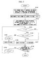
- a flow of the process of the picture dropping determination unit 104 in accordance with the present embodiment will be described in accordance with FIG. 3 .
- the picture is input to the encoder 100 (steps S103 and S107). If the picture number i becomes greater than the number of video pictures n capable of being input, a determination as to whether the difference between the time stamp t i of the determination target picture i and a time stamp t (i-n-d) of a past picture by (n+d), which is determined by the number of video pictures n capable of being input and the number of dropped pictures d, exceeds the frame rate measurement interval T i serving as the reference is made (step S104).
- This determination method is equivalent to a determination as to whether the number of pictures input within a past period having the frame rate measurement interval T i , which is a unit time, from the time stamp t i of the picture (picture i) having the picture number i serving as a starting point by exceeds the number of video pictures n capable of being input.
- step S105 If the difference between the time stamps t i -t (i-n-d) is less than or equal to the frame rate measurement interval T i , 1 is added to the number of dropped pictures d (step S105) and then the picture i is dropped and discarded (step S106). In contrast, if the difference between the time stamps t i -t (i-n-d) is greater than the frame rate measurement interval T i , the encoder 100 can encode the picture I, and thus the picture i is input to the encoder 100.
- step S108 Until processing of the entire video is completed (step S108), the above steps S103 to S109 are iterated while 1 is added to i (step S109).
- the frame rate control and the encoding process by the encoder described above can also be implemented by a computer and a software program, and the program can also be recorded on a computer-readable recording medium and provided through a network.
- FIG. 4 illustrates an example of a configuration of hardware when the apparatus illustrated in FIG. 2 is configured by a computer and a software program.
- the present system has a configuration in which a CPU 50 which execute the program, a memory 51 such as a random access memory (RAM) which stores the program and data to be accessed by the CPU 50, a video signal input unit 52 (which may be a storage unit which stores a video signal by a disk apparatus or the like) which inputs an encoding target video signal from a camera or the like, a program storage apparatus 53 which stores a video encoding program 531 and a frame rate control program 532, and an encoded video stream output unit 54 (which may be a storage unit which stores an encoded video stream by a disk apparatus or the like) are connected by a bus.
- a bus such as a random access memory (RAM) which stores the program and data to be accessed by the CPU 50
- a video signal input unit 52 which may be a storage unit which stores a video signal by a disk apparatus or
- the CPU 50 encodes an input video signal input by the video signal input unit 52 by executing the video encoding program 531 and the frame rate control program 532 loaded from the program storage apparatus 53 to the memory 51, and outputs an encoded video stream of an encoding result to a network or the like via the encoded video stream output unit 54.
- the video encoding program 531 is a program which realizes the function of the encoder 100 of FIG. 2
- the frame rate control program 532 is a program which realizes the function of the frame rate control unit 101 of FIG. 2 .
- the frame rate control program 532 may be embedded in the video encoding program 531 as part of the video encoding program 531.
- the present invention is applicable to, for example, encoding of video.
- it is possible to suppress an instantaneous increase in the computational complexity of an encoder and an information amount of an encoded video bitstream without increasing a delay even when input timing of input video fluctuates.
Landscapes
- Engineering & Computer Science (AREA)
- Multimedia (AREA)
- Signal Processing (AREA)
- Computing Systems (AREA)
- Theoretical Computer Science (AREA)
- Compression Or Coding Systems Of Tv Signals (AREA)
Abstract
Description
- The present invention relates to frame rate control in video coding, and more particularly to a frame rate control method, a frame rate control apparatus, and a frame rate control program which control the computational complexity and an information amount in an encoder.
- Priority is claimed on Japanese Patent Application No.
2012-013773, filed January 26, 2012 - Conventionally, when a frame rate at which encoding is possible is different from a frame rate of video input from an imaging device or the like to an encoder, technology which performs conversion into the frame rate at which the encoding is possible by performing a process of dropping the input video is used (see Patent Document 1).
-
FIG. 5 illustrates a block diagram illustrating a configuration of an apparatus in accordance with the conventional technology.FIG. 6 illustrates a flowchart of a picture dropping determination unit in the conventional technology. - In
FIG. 5 , anencoder 200 is, for example, an apparatus which encodes input video in accordance with an encoding scheme of H.264 or the like and outputs an encoded video stream. Theencoder 200 is provided with: amotion detection unit 203 which performs motion detection for each of blocks obtained by dividing a frame; aprediction unit 204 which performs prediction using a motion vector detected by themotion detection unit 203; anorthogonal transform unit 205 which performs an orthogonal transform on a residual signal between an input signal and a predicted signal in accordance with a discrete cosine transform (DCT) or the like; a quantization unit 206 which quantizes transform coefficients; aninverse quantization unit 207 which inversely quantizes a quantized result; an inverseorthogonal transform unit 208 which performs an inverse orthogonal transform on transform coefficients; a locally decodedpicture storage unit 209 which stores a locally decoded picture obtained by adding the predicted signal to an output of the inverseorthogonal transform unit 208; a variablelength encoding unit 210 which performs variable length encoding on an output of the quantization unit 206; amultiplexing unit 211 which multiplexes encoding information; abuffer unit 212 which stores encoded information and outputs it as the encoded video stream; and acontrol unit 213 which performs encoding control on the quantization unit 206 and the other units in accordance with a generated bit amount or the like. - When a frame rate at which encoding by the
encoder 200 is possible is different from a frame rate of the video input from an imaging device or the like to theencoder 200 measured by a framerate measurement unit 202, a picturedropping determination unit 201 performs conversion into the frame rate at which the encoding is possible by performing a process of dropping the input video. The framerate measurement unit 202 measures the frame rate of the input video and notifies the picturedropping determination unit 201 of the frame rate. - The picture
dropping determination unit 201 executes the process illustrated inFIG. 6 . First, theencoder 200 sets a frame rate TA capable of being input (step S200), designates the frame rate of the input video as CA (step S201), and calculates a dropped frame interval value n = CA/(CA-TA) from CA (step S202). Next, a picture number i is initially set to 1 and the number of dropped pictures d is initially set to 0 (step S203), and the following process is performed. - A determination as to whether a picture i is to be dropped is made based on whether the picture number i of a determination target picture exceeds a value obtained by multiplying n by the number of dropped pictures d so far. That is, a determination as to whether i ≥ n×(d+1) is made, and steps S205 and S206 are executed if i is greater than or equal to n×(d+1). In step S205, 1 is added to d; in step S206, the picture i is dropped. If i is less than n×(d+1), the picture i is not dropped. Until processing of the entire video is completed (YES in step S207), the above steps S204 to S207 are iterated while 1 is added to i (step S208).
- As described above, in the conventional technology, the number of dropped pictures which represents the number of pictures of the video from which one picture is dropped is calculated from a ratio between an input frame rate for the encoder and the frame rate at which the encoding is possible, and a process of dropping the input video is performed in accordance with the calculated number of dropped pictures.
- In order to apply the present technology, the input frame rate CA for the encoder must be known in advance. Thus, it is necessary to measure the frame rate CA of the input video for the encoder using, for example, the frame
rate measurement unit 202 illustrated inFIG. 5 . However, for example, when the input timing of the input video fluctuates, the frame rate at the time of the measurement may not always be maintained. Thus, a situation in which many pictures are unnecessarily dropped or a situation in which the number of times of dropping is insufficient occurs. - Patent Document 1: Japanese Unexamined Patent Application, First Publication No.
2005-328487 - However, in an application for video communication such as a videophone, it is assumed that video is input using a Web camera or the like connected to a personal computer (PC) and encoded by a software encoder and an encoded video stream is transmitted to a reception end. In this case, timing when the video captured by the camera is input to the encoder may not be constant and may fluctuate due to, for example, a lack of resources of a central processing unit (CPU). In such a case, an input frame rate per unit time may be intermittently high.
-
FIG. 7 illustrates an example in which input timing of video fluctuates. Although capturing by a camera is being executed at a fixed frame rate at regular timings, CPU resources become insufficient immediately afterpicture 2 is input and a process in a previous stage of the encoder is delayed, and thuspicture 3 and subsequent pictures are delayed and sequentially input to the encoder. Thereafter, the lack of the resources of the CPU is resolved and the video accumulated in the previous stage of the encoder is input to the encoder one after another. - In an encoder in which a real-time process is assumed, if the number of pictures to be encoded per unit time is increased, a bit amount and the computational complexity are intermittently increased. As illustrated in
FIG. 7 , when a time domain is divided into sections each having a fixed time, while the number of pictures insections 1 to 4 is one, the number of pictures insection 5 is 3, and the necessary bit amount and the necessary computational complexity are about three times compared to those in the other sections. Such fluctuation of the timing of the video input to the encoder causes a delay due to a capacity of a transmission path through which an encoded video stream is transmitted being exceeded as well as packet loss in the worst case, leading to the degradation of video quality at the reception end. - As in the technology disclosed in
Patent Document 1, the number of dropped pictures representing the number of input video pictures from which one picture is dropped is calculated from a ratio between an input frame rate for the encoder and the frame rate at which the encoding is possible, and it is necessary for the input frame rate for the encoder to be known in advance when a dropping process is performed in accordance with the calculated number of dropped pictures. - Thus, the following problems arise even when the input frame rate for the encoder is measured. As in the example of
FIG. 7 , when the number of frames capable of being encoded by the encoder is 1 in one section, the number of frames to be input to the encoder is 1 insections 1 to 4. In view of measurement results ofsections 1 to 4, the number of frames to be input to the encoder is equal to the number of frames capable of being encoded, and thus it is not necessary to drop any frame. However, the number of frames to be input insection 5 is 3. If the input video ofsection 5 is not dropped in view of the measurement results ofsections 1 to 4, video exceeding the number of frames capable of being encoded is input to the encoder. - An object of the present invention is to solve the above problems and to control the computational complexity and an information amount of an encoder within a given range even when the input timing of the input video is not constant and fluctuates.
- In order to solve the above problems, the present invention determines whether to drop an input video frame so that the number of video frames to be encoded is not instantaneously increased. The determination is made based on whether the number of frames input in the past within a unit time from the time when a determination target picture is input exceeds a predetermined threshold value, and the input frame rate for the encoder determined by the input timing of the input video is not used. If the above number of frames exceeds the threshold value, the frame is dropped; otherwise, encoding is performed.
- An operation of the present invention is as follows. The input frame rate for the encoder is not used in a picture dropping determination. Thus, even when the input timing of the input video fluctuates and the frame rate is not constantly maintained, a satisfactory determination result can be obtained and appropriate picture dropping can be performed. Accordingly, even when the input timing of the input video fluctuates, it is possible to prevent the number of video frames to be encoded from being instantaneously increased by using a picture dropping process. That is, it is possible to suppress an instantaneous increase in the computational complexity of an encoder and an instantaneous increase in an information amount of a video bitstream.
- In addition, a determination as to whether the number of pictures input in the past within a unit time from the time when a determination target picture is input exceeds a threshold value calculated from a set frame rate is made, i.e., a determination using only information that is already known when the target picture is input is made, and thus a delay does not occur.
- It is to be noted that because the present technology does not use information during encoding, it can be configured independent of the encoder, and the conventional encoder can be used without modification.
- The present invention provides the following advantages even when the input timing of the input video is not constant and fluctuates.
- (1) It is possible to suppress an instantaneous increase in the computational complexity of an encoder without increasing a delay.
- (2) It is possible to suppress an instantaneous increase in an information amount of an encoded video bitstream without increasing a delay.
-
-
FIG. 1 is a diagram illustrating an example of a picture dropping process in accordance with an example of the present invention. -
FIG. 2 is a block diagram illustrating a configuration of an apparatus in accordance with an embodiment of the present invention. -
FIG. 3 is a flowchart of a picture dropping determination unit in accordance with an embodiment of the present invention. -
FIG. 4 is a diagram illustrating an example of a configuration of a system when the apparatus of the present embodiment is implemented using a computer and a software program. -
FIG. 5 is a block diagram illustrating a configuration of an apparatus in accordance with a conventional technology. -
FIG. 6 is a flowchart of a picture dropping determination unit in the conventional technology. -
FIG. 7 is a diagram illustrating an example in which input timing of video fluctuates. - Hereinafter, examples and embodiments of the present invention will be described in detail using the drawings.
- A frame rate Fr capable of being input to an encoder and a reference frame rate measurement interval Ti are set based on the throughput or the like of the encoder. Based on the reference frame rate measurement interval Ti, the number of video pictures n capable of being input within the measurement interval is calculated in advance in accordance with the following equation.

- First to nth input video pictures input immediately after encoding has started are not designated as a dropping target, and a dropping process is performed on future input video pictures after the nth picture.
-
FIG. 1 illustrates an example of a picture dropping process in accordance with an example of the present invention. In the example ofFIG. 1 , the frame rate Fr and the reference frame rate measurement interval Ti are as follows.

- The number of video pictures n capable of being input within the measurement interval Ti is calculated as n = 0.006x500 = 3.
- Hereinafter, a time when each picture is input in the present process, i.e., a time when each picture is output from the previous stage of the encoder such as a camera, is stamped as a time stamp of each picture and used in a determination. Because n = 3,
pictures 1 to 3 are designated as a non-dropping target and unconditionally input to the encoder. Whenpicture 4 is input, if the time stamp ofpicture 1, which is a past frame by n (= 3) frames, is past relative to the time before the time whenpicture 4 is input by Ti (= 500 msec), in other words, when the time stamp ofpicture 1 is designated as t1 and the time stamp ofpicture 4 is designated as t4, a determination as to whether the following equation is established is made and if the following equation is established,picture 4 is not dropped.
- In the case of the example of
FIG. 1 , (t4-t1) > 500 is established, which meets this condition. It is to be noted that this determination is equivalent to a determination as to whether the number of pictures input within a past period having the frame rate measurement interval Ti, which is a unit time, from the time stamp ofpicture 4 serving as a starting point exceeds the number of video pictures n capable of being input. - A similar comparison is performed between
picture 5 andpicture 2, and a determination as to whetherpicture 2 does not exist within past Ti (= 500 msec) is made. That is, the determination of the following equation is made.
- In this example,
picture 5 is dropped because (t5-t2) ≤ 500 is established. - Next, a similar comparison is performed on
picture 6, and a dropped picture is not counted when a picture of a comparison target is searched for. Becausepicture 5 has been dropped, the comparison target ofpicture 6 becomespicture 2. In this example, (t6-t2) is greater than 500 (msec). Thus,picture 6 is not dropped. -
FIG. 2 is a block diagram illustrating a configuration of an apparatus in accordance with an embodiment of the present invention.FIG. 3 is a flowchart of a picture dropping determination unit in accordance with an embodiment of the present invention. - In
FIG. 2 , anencoder 100 is, for example, an apparatus which encodes input video in accordance with an encoding scheme such as H.264 and outputs an encoded video stream. A framerate control unit 101 adjusts a frame rate of input video for theencoder 100 so as to match a frame rate at which theencoder 100 is capable of encoding by means of dropping of a picture. It is to be noted that the framerate control unit 101 may be embedded in theencoder 100. The encoding scheme of theencoder 100 is not limited to H.264 and it may be another encoding scheme such as Moving Picture Experts Group (MPEG)-2. - A frame of input video is first input to the frame
rate control unit 101. A time-stamp stamping unit 102 stamps a time stamp ti on the input frame in accordance with a time measured by atime measurement unit 103. A picture droppingdetermination unit 104 determines whether to drop a picture of the input frame from the frame rate Fr at which encoding by theencoder 100 is possible and the reference frame rate measurement interval Ti, drops the picture of the input frame, if necessary, and inputs its result to theencoder 100. - A frame input to the
encoder 100 is divided into blocks, and amotion detection unit 105 performs motion detection. Aprediction unit 106 performs prediction using a motion vector detected by amotion detection unit 105. Anorthogonal transform unit 107 performs an orthogonal transform on a residual signal between an input signal and a predicted signal in accordance with a DCT or the like. Aquantization unit 108 quantizes transform coefficients obtained by the orthogonal transform and outputs the result to aninverse quantization unit 109 and a variablelength encoding unit 112. Theinverse quantization unit 109 performs inverse quantization on the quantized result. An inverseorthogonal transform unit 110 performs an inverse orthogonal transform on transform coefficients obtained by the inverse quantization. A locally decodedpicture storage unit 111 stores a locally decoded picture obtained by adding a decoded residual signal, which is an output of the inverseorthogonal transform unit 110, to the predicted signal, which is an output of theprediction unit 106. This locally decoded picture is used as a reference picture in subsequent predictive encoding. - The variable
length encoding unit 112 performs variable length encoding on the output of thequantization unit 108. Amultiplexing unit 113 multiplexes an output of the variablelength encoding unit 112 and encoding information such as a motion vector, and outputs to abuffer unit 114. Data stored in thebuffer unit 114 is output as an encoded video stream. Acontrol unit 115 performs encoding control on thequantization unit 108 and the other units in accordance with a generated bit amount or the like. A configuration and operation of theabove encoder 100 are similar to those of theconventional encoder 200 described with reference toFIG. 5 . The framerate control unit 101, which performs dropping adjustment of an input frame for theencoder 100, is different from the conventional technology. - A flow of the process of the picture dropping
determination unit 104 in accordance with the present embodiment will be described in accordance withFIG. 3 . - The picture dropping
determination unit 104 first sets the frame rate Fr (frame rate capable of being input) at which encoding by theencoder 100 is possible and the frame rate measurement interval Ti serving as a reference (step S100), and a time stamp of an input picture i is designated as ti (step S101). Next, the number of video pictures n capable of being input is calculated from n = Fr×Ti, the picture number i is set to 1, and the number of dropped pictures d is set to 0 (step S102). Thereafter, the following process is iterated for every picture. - Because a picture dropping process is not performed if the picture number i is less than or equal to the number of video pictures n capable of being input, the picture is input to the encoder 100 (steps S103 and S107). If the picture number i becomes greater than the number of video pictures n capable of being input, a determination as to whether the difference between the time stamp ti of the determination target picture i and a time stamp t(i-n-d) of a past picture by (n+d), which is determined by the number of video pictures n capable of being input and the number of dropped pictures d, exceeds the frame rate measurement interval Ti serving as the reference is made (step S104). This determination method is equivalent to a determination as to whether the number of pictures input within a past period having the frame rate measurement interval Ti, which is a unit time, from the time stamp ti of the picture (picture i) having the picture number i serving as a starting point by exceeds the number of video pictures n capable of being input.
- If the difference between the time stamps ti-t(i-n-d) is less than or equal to the frame rate measurement interval Ti, 1 is added to the number of dropped pictures d (step S105) and then the picture i is dropped and discarded (step S106). In contrast, if the difference between the time stamps ti-t(i-n-d) is greater than the frame rate measurement interval Ti, the
encoder 100 can encode the picture I, and thus the picture i is input to theencoder 100. - Until processing of the entire video is completed (step S108), the above steps S103 to S109 are iterated while 1 is added to i (step S109).
- The frame rate control and the encoding process by the encoder described above can also be implemented by a computer and a software program, and the program can also be recorded on a computer-readable recording medium and provided through a network.
-
FIG. 4 illustrates an example of a configuration of hardware when the apparatus illustrated inFIG. 2 is configured by a computer and a software program. The present system has a configuration in which aCPU 50 which execute the program, amemory 51 such as a random access memory (RAM) which stores the program and data to be accessed by theCPU 50, a video signal input unit 52 (which may be a storage unit which stores a video signal by a disk apparatus or the like) which inputs an encoding target video signal from a camera or the like, aprogram storage apparatus 53 which stores avideo encoding program 531 and a framerate control program 532, and an encoded video stream output unit 54 (which may be a storage unit which stores an encoded video stream by a disk apparatus or the like) are connected by a bus. - The
CPU 50 encodes an input video signal input by the videosignal input unit 52 by executing thevideo encoding program 531 and the framerate control program 532 loaded from theprogram storage apparatus 53 to thememory 51, and outputs an encoded video stream of an encoding result to a network or the like via the encoded videostream output unit 54. Thevideo encoding program 531 is a program which realizes the function of theencoder 100 ofFIG. 2 , and the framerate control program 532 is a program which realizes the function of the framerate control unit 101 ofFIG. 2 . It is to be noted that the framerate control program 532 may be embedded in thevideo encoding program 531 as part of thevideo encoding program 531. - While examples and embodiments of the present invention have been described above with reference to the drawings, it is apparent that the examples and the embodiments are mere illustrations of the present invention and that the present invention is not limited to the examples and embodiments described above. Therefore, additions, omissions, substitutions, and other modifications of structural elements can be made without departing from the spirit or scope of the present invention.
- The present invention is applicable to, for example, encoding of video. In accordance with the present invention, it is possible to suppress an instantaneous increase in the computational complexity of an encoder and an information amount of an encoded video bitstream without increasing a delay even when input timing of input video fluctuates.
-
- 100
- Encoder
- 101
- Frame rate control unit
- 102
- Time-stamp stamping unit
- 103
- Time measurement unit
- 104
- Picture dropping determination unit
- 105
- Motion detection unit
- 106
- Prediction unit
- 107
- Orthogonal transform unit
- 108
- Quantization unit
- 109
- Inverse quantization unit
- 110
- Inverse orthogonal transform unit
- 111
- Locally decoded picture storage unit
- 112
- Variable length encoding unit
- 113
- Multiplexing unit
- 114
- Buffer unit
- 115
- Control unit
Claims (4)
- A frame rate control method for adjusting a frame rate of input video to a frame rate at which an encoder is able to perform encoding, the frame rate control method comprising:a step of determining whether the number of pictures input in the past within a predetermined time from a time when a determination target picture of dropping is input exceeds a predetermined threshold value; anda step of discarding the determination target picture if the number of pictures exceeds the threshold value and designating the determination target picture as an encoding target if the number of pictures does not exceed the threshold value.
- The frame rate control method according to claim 1, wherein, in the determining step, a determination as to whether the number of input pictures exceeds the predetermined threshold value is made by determining whether the difference between a time stamp ti of the determination target picture and a time stamp t(i-n-d) of a past picture by (n+d) which is determined by the number of pictures n capable of being encoded by the encoder within a frame rate measurement interval Ti which serves as a reference and which is the predetermined time and the number of dropped pictures d, exceeds the frame rate measurement interval Ti.
- A frame rate control apparatus which adjusts a frame rate of input video to a frame rate at which an encoder is able to perform encoding, the frame rate control apparatus comprising:a determination unit which determines whether the number of pictures input in the past within a predetermined time from a time when a determination target picture of dropping is input exceeds a predetermined threshold value; anda dropping unit which discards the determination target picture if the number of pictures exceeds the threshold value and designates the determination target picture as an encoding target if the number of pictures does not exceed the threshold value.
- A frame rate control program for causing a computer to execute the frame rate control method according to claim 1 or 2.
Applications Claiming Priority (2)
| Application Number | Priority Date | Filing Date | Title |
|---|---|---|---|
| JP2012013773A JP5843631B2 (en) | 2012-01-26 | 2012-01-26 | Frame rate control method, frame rate control device, and frame rate control program |
| PCT/JP2013/051072 WO2013111701A1 (en) | 2012-01-26 | 2013-01-21 | Frame rate control method, frame rate control device, and frame rate control program |
Publications (2)
| Publication Number | Publication Date |
|---|---|
| EP2779645A1 true EP2779645A1 (en) | 2014-09-17 |
| EP2779645A4 EP2779645A4 (en) | 2015-06-03 |
Family
ID=48873421
Family Applications (1)
| Application Number | Title | Priority Date | Filing Date |
|---|---|---|---|
| EP13740874.6A Ceased EP2779645A4 (en) | 2012-01-26 | 2013-01-21 | IMAGE FREQUENCY CONTROL METHOD, IMAGE FREQUENCY CONTROL DEVICE, AND PROGRAM IMAGE FREQUENCY CONTROL PROGRAM |
Country Status (10)
| Country | Link |
|---|---|
| US (1) | US9712827B2 (en) |
| EP (1) | EP2779645A4 (en) |
| JP (1) | JP5843631B2 (en) |
| KR (1) | KR101659514B1 (en) |
| CN (1) | CN104471936B (en) |
| BR (1) | BR112014017565A8 (en) |
| CA (1) | CA2859631A1 (en) |
| RU (1) | RU2014129008A (en) |
| TW (1) | TWI536846B (en) |
| WO (1) | WO2013111701A1 (en) |
Families Citing this family (6)
| Publication number | Priority date | Publication date | Assignee | Title |
|---|---|---|---|---|
| US10425615B2 (en) | 2017-05-10 | 2019-09-24 | Mediatek Inc. | Apparatuses and methods for dynamic frame rate adjustment |
| JP7208531B2 (en) * | 2019-05-31 | 2023-01-19 | 日本電信電話株式会社 | Synchronization control device, synchronization control method and synchronization control program |
| CN111741305B (en) * | 2020-08-27 | 2020-11-24 | 科大讯飞(苏州)科技有限公司 | Video coding method and device, electronic equipment and readable storage medium |
| CN112423072B (en) * | 2020-09-02 | 2025-02-07 | 上海幻电信息科技有限公司 | Video push method and system in live broadcast scenario |
| CN114040247A (en) * | 2021-11-09 | 2022-02-11 | 新智认知数据服务有限公司 | Network video stream processing method, electronic equipment and computer readable storage medium |
| CN116132680A (en) * | 2023-02-13 | 2023-05-16 | 深圳市酷开网络科技股份有限公司 | Frame rate self-adaption method and device based on large-screen video transmission and intelligent terminal |
Family Cites Families (36)
| Publication number | Priority date | Publication date | Assignee | Title |
|---|---|---|---|---|
| JP2603931B2 (en) * | 1987-02-04 | 1997-04-23 | 株式会社東芝 | Image transmission device |
| US5619281A (en) * | 1994-12-30 | 1997-04-08 | Daewoo Electronics Co., Ltd | Method and apparatus for detecting motion vectors in a frame decimating video encoder |
| EP1357758A3 (en) * | 1995-08-02 | 2004-10-27 | Matsushita Electric Industrial Co., Ltd. | Video coding device and video transmission system using the same, quantization control method and average throughput calculation method used therein |
| US6633609B1 (en) * | 1996-12-24 | 2003-10-14 | Intel Corporation | Method and apparatus for bit rate control in a digital video environment for arbitrary bandwidth |
| US6031584A (en) * | 1997-09-26 | 2000-02-29 | Intel Corporation | Method for reducing digital video frame frequency while maintaining temporal smoothness |
| US6212232B1 (en) * | 1998-06-18 | 2001-04-03 | Compaq Computer Corporation | Rate control and bit allocation for low bit rate video communication applications |
| JP4069524B2 (en) * | 1998-11-10 | 2008-04-02 | ソニー株式会社 | Transmission method and apparatus |
| JP3324556B2 (en) * | 1999-04-13 | 2002-09-17 | 日本電気株式会社 | Video recording method |
| JP2001346216A (en) * | 2000-06-06 | 2001-12-14 | Toshiba Corp | Moving image compression method and information processing apparatus |
| KR100341063B1 (en) * | 2000-06-28 | 2002-06-20 | 송문섭 | Rate control apparatus and method for real-time video communication |
| JP2002125226A (en) * | 2000-10-17 | 2002-04-26 | Matsushita Electric Ind Co Ltd | Frame rate control method and image transmission device |
| JP3823044B2 (en) * | 2001-10-31 | 2006-09-20 | パナソニック モバイルコミュニケーションズ株式会社 | Time stamp value controller |
| KR100468726B1 (en) * | 2002-04-18 | 2005-01-29 | 삼성전자주식회사 | Apparatus and method for performing variable bit rate control in real time |
| KR100484148B1 (en) * | 2002-07-27 | 2005-04-18 | 삼성전자주식회사 | Advanced method for rate control and apparatus thereof |
| US7133448B2 (en) * | 2002-11-07 | 2006-11-07 | Silicon Integrated Systems Corp. | Method and apparatus for rate control in moving picture video compression |
| US8054880B2 (en) * | 2004-12-10 | 2011-11-08 | Tut Systems, Inc. | Parallel rate control for digital video encoder with multi-processor architecture and picture-based look-ahead window |
| BRPI0411757A (en) * | 2003-06-26 | 2006-09-19 | Thomson Licensing | multipass video rate control to match sliding window channel constraints |
| KR100505699B1 (en) * | 2003-08-12 | 2005-08-03 | 삼성전자주식회사 | Encoding rate controller of video encoder providing for qualitative display using real time variable bit-rate control, video data transmission system having it and method thereof |
| KR100594056B1 (en) * | 2003-09-01 | 2006-07-03 | 삼성전자주식회사 | H.263 / PMP video encoder for efficient bit rate control and its control method |
| US7330509B2 (en) | 2003-09-12 | 2008-02-12 | International Business Machines Corporation | Method for video transcoding with adaptive frame rate control |
| JP3846490B2 (en) * | 2004-05-17 | 2006-11-15 | セイコーエプソン株式会社 | Image data compression apparatus, electronic device, and image data compression method |
| AU2005267171A1 (en) | 2004-07-20 | 2006-02-02 | Qualcomm Incorporated | Method and apparatus for encoder assisted-frame rate up conversion (EA-FRUC) for video compression |
| TWI280798B (en) * | 2004-09-22 | 2007-05-01 | Via Tech Inc | Apparatus and method of adaptive de-interlace of image |
| US7738561B2 (en) * | 2004-11-16 | 2010-06-15 | Industrial Technology Research Institute | MPEG-4 streaming system with adaptive error concealment |
| JP4040052B2 (en) | 2005-05-24 | 2008-01-30 | 株式会社日立国際電気 | Image data compression device |
| JP2006352529A (en) * | 2005-06-16 | 2006-12-28 | Olympus Corp | Imaging apparatus |
| JP4623650B2 (en) * | 2005-09-06 | 2011-02-02 | パナソニック株式会社 | Moving picture coding apparatus and moving picture coding method |
| US20080151998A1 (en) * | 2006-12-21 | 2008-06-26 | General Instrument Corporation | Method and Apparatus for Providing Rate Control for Panel-Based Real Time Video Encoder |
| US8396118B2 (en) * | 2007-03-19 | 2013-03-12 | Sony Corporation | System and method to control compressed video picture quality for a given average bit rate |
| JPWO2008129648A1 (en) | 2007-04-13 | 2010-07-22 | 三菱電機株式会社 | Frame rate conversion apparatus, frame rate conversion method, and moving picture encoding apparatus |
| CN101072339B (en) | 2007-06-12 | 2010-06-09 | 北京中星微电子有限公司 | Method and system for controlling play frame rate synchronization |
| US8295344B2 (en) * | 2007-10-22 | 2012-10-23 | Broadcom Corporation | Adaptive rate control for encoding of variable frame rate video sources |
| CN100589570C (en) * | 2008-01-08 | 2010-02-10 | 北京中星微电子有限公司 | A frame rate control method and device |
| JP5479470B2 (en) * | 2009-06-23 | 2014-04-23 | パナソニック株式会社 | Moving picture coding method, moving picture coding apparatus, program, and integrated circuit |
| US8902995B2 (en) * | 2009-07-02 | 2014-12-02 | Qualcomm Incorporated | Transmitter quieting and reduced rate encoding |
| JP2012242821A (en) * | 2011-05-16 | 2012-12-10 | Sony Mobile Communications Inc | Display image generation method |
-
2012
- 2012-01-26 JP JP2012013773A patent/JP5843631B2/en active Active
-
2013
- 2013-01-21 RU RU2014129008A patent/RU2014129008A/en not_active Application Discontinuation
- 2013-01-21 US US14/365,892 patent/US9712827B2/en active Active
- 2013-01-21 CA CA2859631A patent/CA2859631A1/en not_active Abandoned
- 2013-01-21 WO PCT/JP2013/051072 patent/WO2013111701A1/en not_active Ceased
- 2013-01-21 BR BR112014017565A patent/BR112014017565A8/en not_active IP Right Cessation
- 2013-01-21 CN CN201380005516.9A patent/CN104471936B/en active Active
- 2013-01-21 EP EP13740874.6A patent/EP2779645A4/en not_active Ceased
- 2013-01-21 KR KR1020147017401A patent/KR101659514B1/en active Active
- 2013-01-24 TW TW102102597A patent/TWI536846B/en active
Also Published As
| Publication number | Publication date |
|---|---|
| TW201338546A (en) | 2013-09-16 |
| JP2013153366A (en) | 2013-08-08 |
| CA2859631A1 (en) | 2013-08-01 |
| CN104471936A (en) | 2015-03-25 |
| BR112014017565A8 (en) | 2017-07-04 |
| US20140341279A1 (en) | 2014-11-20 |
| KR20140098197A (en) | 2014-08-07 |
| TWI536846B (en) | 2016-06-01 |
| BR112014017565A2 (en) | 2017-06-13 |
| US9712827B2 (en) | 2017-07-18 |
| KR101659514B1 (en) | 2016-09-23 |
| EP2779645A4 (en) | 2015-06-03 |
| CN104471936B (en) | 2018-01-09 |
| JP5843631B2 (en) | 2016-01-13 |
| RU2014129008A (en) | 2016-03-20 |
| WO2013111701A1 (en) | 2013-08-01 |
Similar Documents
| Publication | Publication Date | Title |
|---|---|---|
| EP3562155B1 (en) | Bit rate control method and device | |
| EP2985997B1 (en) | Low latency video encoder | |
| US9712827B2 (en) | Frame rate control method and apparatus for encoding image based on threshold value | |
| US6408027B2 (en) | Apparatus and method for coding moving picture | |
| US20100158126A1 (en) | Integrated Transcoding | |
| CA2361047C (en) | Method and apparatus for assuring sufficient bandwidth of a statistical multiplexer | |
| EP2206348B1 (en) | Method and apparatus for rate control accuracy in video encoding and decoding | |
| WO2006067374A1 (en) | Rate control with buffer underflow prevention | |
| JP2002232882A (en) | Moving picture encoder using a priori analysis, moving picture encoding method, and its program | |
| CN101637025A (en) | Quantization control method and apparatus, program therefor, and recording medium having the program recorded thereon | |
| US20020054635A1 (en) | Image transmitting method and apparatus and image receiving method and apparatus | |
| US20110317756A1 (en) | Coding device, imaging device, coding transmission system, and coding method | |
| JP6344386B2 (en) | Time-series data encoding apparatus, method and program, and time-series data re-encoding apparatus, method and program | |
| JP4309703B2 (en) | Coding error estimation device | |
| KR20130032807A (en) | Method and apparatus for encoding a moving picture | |
| Lee | Video traffic prediction based on source information and preventive channel rate decision for RCBR | |
| WO2006067375A1 (en) | Rate control with decoding buffer overflow prevention | |
| WO2007145137A1 (en) | Image coding device and image coding method | |
| Yunus et al. | A rate control model of MPEG-4 encoder for video transmission over Wireless Sensor Network | |
| CN114422783A (en) | Video coding method, electronic device and storage medium | |
| JP2023007048A (en) | Streaming server, transmission method, and program | |
| KR100918560B1 (en) | Apparatus and method for predicting bit rate for real-time H.263 video coding rate control | |
| EP2160036A2 (en) | Method of bit rate control in digital video compression systems based on MJPEG | |
| JP2010278730A (en) | Moving picture coding apparatus and moving picture coding method | |
| US20150327279A1 (en) | Transmission apparatus, method for controlling transmission, and recording medium |
Legal Events
| Date | Code | Title | Description |
|---|---|---|---|
| PUAI | Public reference made under article 153(3) epc to a published international application that has entered the european phase |
Free format text: ORIGINAL CODE: 0009012 |
|
| 17P | Request for examination filed |
Effective date: 20140613 |
|
| AK | Designated contracting states |
Kind code of ref document: A1 Designated state(s): AL AT BE BG CH CY CZ DE DK EE ES FI FR GB GR HR HU IE IS IT LI LT LU LV MC MK MT NL NO PL PT RO RS SE SI SK SM TR |
|
| DAX | Request for extension of the european patent (deleted) | ||
| RIN1 | Information on inventor provided before grant (corrected) |
Inventor name: KYOCHI, SEISUKE Inventor name: SHIMIZU, ATSUSHI Inventor name: NAKAMURA, KEN Inventor name: KITAHARA, MASAKI Inventor name: ONO, NAOKI |
|
| RA4 | Supplementary search report drawn up and despatched (corrected) |
Effective date: 20150504 |
|
| RIC1 | Information provided on ipc code assigned before grant |
Ipc: H04N 19/00 20140101AFI20150504BHEP |
|
| 17Q | First examination report despatched |
Effective date: 20151221 |
|
| APBK | Appeal reference recorded |
Free format text: ORIGINAL CODE: EPIDOSNREFNE |
|
| APBN | Date of receipt of notice of appeal recorded |
Free format text: ORIGINAL CODE: EPIDOSNNOA2E |
|
| APBR | Date of receipt of statement of grounds of appeal recorded |
Free format text: ORIGINAL CODE: EPIDOSNNOA3E |
|
| APAF | Appeal reference modified |
Free format text: ORIGINAL CODE: EPIDOSCREFNE |
|
| APAM | Information on closure of appeal procedure modified |
Free format text: ORIGINAL CODE: EPIDOSCNOA9E |
|
| APBB | Information on closure of appeal procedure deleted |
Free format text: ORIGINAL CODE: EPIDOSDNOA9E |
|
| APBT | Appeal procedure closed |
Free format text: ORIGINAL CODE: EPIDOSNNOA9E |
|
| REG | Reference to a national code |
Ref country code: DE Ref legal event code: R003 |
|
| APBT | Appeal procedure closed |
Free format text: ORIGINAL CODE: EPIDOSNNOA9E |
|
| STAA | Information on the status of an ep patent application or granted ep patent |
Free format text: STATUS: THE APPLICATION HAS BEEN REFUSED |
|
| 18R | Application refused |
Effective date: 20220203 |