EP2779388A1 - Linear motor and linear conveyance device - Google Patents
Linear motor and linear conveyance device Download PDFInfo
- Publication number
- EP2779388A1 EP2779388A1 EP12846037.5A EP12846037A EP2779388A1 EP 2779388 A1 EP2779388 A1 EP 2779388A1 EP 12846037 A EP12846037 A EP 12846037A EP 2779388 A1 EP2779388 A1 EP 2779388A1
- Authority
- EP
- European Patent Office
- Prior art keywords
- upstream
- downstream
- sensor
- detecting means
- sensor substrate
- Prior art date
- Legal status (The legal status is an assumption and is not a legal conclusion. Google has not performed a legal analysis and makes no representation as to the accuracy of the status listed.)
- Granted
Links
Images



Classifications
-
- H—ELECTRICITY
- H02—GENERATION; CONVERSION OR DISTRIBUTION OF ELECTRIC POWER
- H02K—DYNAMO-ELECTRIC MACHINES
- H02K41/00—Propulsion systems in which a rigid body is moved along a path due to dynamo-electric interaction between the body and a magnetic field travelling along the path
- H02K41/02—Linear motors; Sectional motors
- H02K41/03—Synchronous motors; Motors moving step by step; Reluctance motors
- H02K41/031—Synchronous motors; Motors moving step by step; Reluctance motors of the permanent magnet type
-
- H—ELECTRICITY
- H02—GENERATION; CONVERSION OR DISTRIBUTION OF ELECTRIC POWER
- H02K—DYNAMO-ELECTRIC MACHINES
- H02K11/00—Structural association of dynamo-electric machines with electric components or with devices for shielding, monitoring or protection
- H02K11/20—Structural association of dynamo-electric machines with electric components or with devices for shielding, monitoring or protection for measuring, monitoring, testing, protecting or switching
- H02K11/21—Devices for sensing speed or position, or actuated thereby
- H02K11/215—Magnetic effect devices, e.g. Hall-effect or magneto-resistive elements
Definitions
- the present invention relates to a linear motor and a linear conveyance device.
- a linear motor comprises a motor body in which a stator is disposed, a mover that faces the stator, and a slider in which the mover is disposed.
- the slider moves relative to the motor body along a predetermined moving path.
- One of the stator and the mover may be constituted by a plurality of permanent magnets and the other may be constituted by an electromagnet. Otherwise, both the stator and the mover may be constituted by an electromagnet.
- the electromagnet comprises a plurality of cores arranged along the moving path.
- a coil is attached to each coil.
- the linear motor comprises a control device. The control device controls conduction of the coils and causes the slider to move along the moving path while generating attractive force between the stators.
- a linear scale is provided in the linear motor.
- a linear scale is attached to a slider.
- the device of Patent Document 1 further comprises a position detection sensor that detects the linear scale to output a wave signal, an origin sensor that outputs a signal for specifying an origin position of the wave signal, and a sensor substrate for attaching the origin sensor to a motor body.
- the position detection sensor and the origin sensor output signals according to a moving position of the slider, and the position of the slider is detected based on these signals.
- the sensor substrate of Patent Document 1 is disposed in a central portion of the stator attached to the motor body in a direction along the moving path. Moreover, the sensors are also laid out in the central portion of the stator. For this reason, there is a problem in that it is not possible to detect the position until the linear scale of the slider reaches the origin sensor disposed in the central portion of the stator. Therefore, as disclosed in Patent Document 2, the present applicant proposes a linear motor in which an origin sensor is disposed at a position where the origin sensor meets an end of a stator in the direction along a moving path.
- the linear motor employs a stator unit that comprises a motor body and stators mounted on the motor body.
- stator units are connected along the moving path to form a linear motor together with a slider that has a mover.
- the stator unit comprises a sensor head, as a sensor substrate, for each stator.
- an origin sensor is disposed at a position where the origin sensor meets an end of the stator in the direction along the moving path.
- stator unit when the motor body is constituted by one stator unit, it is necessary to protect the protruding portion of the sensor head. Thus, it may be difficult to handle the linear motor.
- a plurality of stator units when a plurality of stator units is connected to a base, it is necessary to disassemble the stator unit itself. That is, it is necessary to separate the sensor head from the stator unit, install the motor body of the stator unit, and then attach the sensor head to the installed motor body again. For this reason, the operation of connecting the stator units or disassembling the linear motor may become complicated.
- a linear motor comprising: a slider having a mover; a motor body disposed in a moving path of the slider; and stators attached to the motor body, these stators are arranged along the moving path so that the stators face the mover and move the slider along the moving path while generating attractive force between the stators.
- Each stator unit comprises: a plurality of sensor substrates attached to the respective stators such that the plurality of sensor substrates is sized within a dimension of the respective stators in a moving direction extending along the moving path; upstream-side position detecting means attached to each sensor substrate, the upstream-side position detecting means being configured to detect the slider in an upstream portion of each sensor substrate in the moving direction and output a position detection signal; downstream-side position detecting means attached to each sensor substrate, the downstream-side position detecting means being configured to detect the slider in a downstream portion of each sensor substrate in the moving direction and output a position detection signal; a position detection signal adding unit attached to each sensor substrate, the position detection signal adding unit being configured to add the position detection signal from the downstream-side position detecting means of a sensor substrate being adjacent to an upstream side of one sensor substrate in the moving direction and the position detection signal from the upstream-side position detecting means of a sensor substrate being adjacent to a downstream side of the one sensor substrate in the moving direction to obtain an addition signal, and the position detection signal
- a linear conveyance device in which the linear motor is configured to allow a conveying article to be mounted on the slider.
- the present invention provides a significant advantageous effect that a function of detecting the position of the slider in a longer stroke range than the stator can be provided and a device having easy handling properties can be provided.
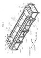
- a linear conveyance device 10 comprises a base 11 that extends in a rectangular form in a plan view, a pair of linear driving units 20A and 20B formed on the base 11, and a slider 30 driven by the linear driving units 20A and 20B.
- a first circulating device 40 that circulates the slider 30 from a downstream end of one linear driving unit 20A (on the forward moving side) to an upstream end of the other linear driving unit 20B (on the backward moving side) and a second circulating device 50 that circulates the slider 30 from the downstream end of the other linear driving unit 20B to the upstream end of one linear driving unit 20A are provided.
- the base 11 is formed by combining a plurality of tables 11A.
- Each table 11A is formed by forming a rectangular parallelepiped frame as a framework.
- Each table 11A comprises a bottom plate, height-adjustable legs attached to four corners of the lower surface of the bottom plate, and a ceiling plate provided above the legs as the framework.
- a longitudinal direction of the base 11 is referred to as an X-direction
- a horizontal direction orthogonal to the X-direction is referred to as a Y-direction.
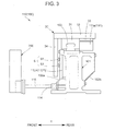
- one end side (the left side of Fig. 3 ) of the Y-direction is referred to as a front side.
- the linear driving units 20A and 20B extend in parallel on the base 11 along the X-direction.
- the front linear driving unit 20A (on the front side of Fig. 1 ) forms a forward path (moving path) along which the slider 30 is driven from one end side in the X-direction to the other end side.
- the rear linear driving unit 20B (on the rear side of Fig. 1 ) forms a backward path (moving path) along which the slider 30 is driven from the other end side in the X-direction to one end side.
- these linear driving units 20A and 20B form linear motors.
- Each of the linear motors (the linear driving units 20A and 20B) comprises a plurality of stator units 100 and a rail 103.
- the stator units 100 have the same specifications and are arranged along the X-direction.
- the rail 103 is fixed to the upper portion of the plurality of stator units 100 along the X-direction.
- stator units 100 of the linear driving unit 20A will be described.
- each stator unit 100 is a device in which a set of four stators 110 having approximately the same specifications is connected.
- the stator unit 100 comprises a unit frame 101.
- the unit frame 101 is formed into a rectangular shape in a plan view and is disposed so that the longitudinal direction thereof extends in the X-direction.
- the unit frame 101 is fixed to an upper surface of the base 11 by bolts (not illustrated).
- the unit frame 101 is an example of a member that constitutes a motor body of each stator unit 100.
- covers 102a (see Fig. 3 ) and 102b are attached to both front and rear sides of each unit frame 101.
- a set of four stators 110 is assembled to the upper portion of the unit frame 101.
- the stators 110 are arranged in parallel to the rail 103 on the rear side of the rail 103.
- Each stator 110 is constituted by a plurality of magnetic electromagnets 111.
- the magnetic electromagnet 111 comprises a core 111a.
- the cores 111 a are arranged in a line in the X-direction.
- the upper ends of the cores 111a are magnetic polarities and the lower ends are connected to an adjacent core 111a to form an interdigital shape.
- a magnetic coil is wound around the core.
- Reference numeral 111b is an assembly of magnetic coils.
- the magnetic coil assembly 111b is arranged in the longitudinal direction of the unit frame 101.
- a length Ls in the X-direction (the direction along the moving path) of the stator 110 is set to exactly 1/4 of a length Lf in the X-direction of the unit frame 101.
- stators 110 are arranged in the longitudinal direction on the upper surface of the unit frame 101.
- the stators 110 are connected linearly at an equal pitch along the X-direction.
- the length Ls in the X-direction of the stator 110, the length L in the X-direction of the unit frame 101, and a magnetic polarity pitch are set so that a distance (magnetic polarity pitch) between the cores 111a adjacent at the end of the stator 110 is the same as a distance between the cores 111a adjacent in an intermediate point of the stator 110.
- the stator unit 100 comprises a controller 200 (schematically illustrated in Fig. 3 ) that is provided in each stator 110.
- the controller 200 is constituted by a microprocessor and other electronic components and the like.
- the controllers 200 obtain the positions of the slider 30 relative to the corresponding stators 110 and individually control conduction of the respective magnetic coils of the corresponding stators 110 so as to correspond to the obtained positions.
- the controllers 200 are configured to control the current supplied to the corresponding stators 110 based on a program or the control of a main control device that controls the entire linear conveyance device.
- each controller 200 is configured to be able to communicate with each other.
- FIG. 4 four substrates 112A, 112B, 112C, and 112D are attached to the front side in the Y-direction of the unit frame 101 so as to correspond to the four stators 110 comprised in the unit frame 101.
- Plates 113 are attached to the respective substrates 112A, 112B, 112C, and 112D.
- a connector 114 is disposed on the plate 113.
- a wire harness 115 for realizing wire connection to an external device is connected to the connector 114.
- the wire harness 115 is disposed so as to extend toward the front side in the Y-direction of the unit frame 101 (see Fig. 3 ).
- the length in the X-direction of the substrates 112A, 112B, 112C, and 112D is set to be approximately the same as the length Ls of the stator 110.
- the substrates 112A, 112B, 112C, and 112D are arranged in the X-direction at the same arrangement pitch as the stators 110. Thus, all substrates 112A, 112B, 112C, and 112D fit within the front surface of the unit frame 101 (that is, the substrates do not protrude from the front surface).
- the arrangement pitch in the X-direction of the substrate 112A attached to one end side of the unit frame 101 and the substrate 112D attached to the other end side of another unit frame 101 being adjacent to one end side of the substrate 112A is set to be the same as the arrangement pitch (or the arrangement pitch of the substrates 112C and 112D) of the substrates 112A and 112B attached to the unit frame 101.
- the connector 114 disposed on the plate 113 is electrically connected to the stator 110 corresponding to the substrate 112A (112B, 112C, or 112D) of the plate 113, sensors disposed on the substrate 112A (112B, 112C, or 112D) of the plate 113, and an adder circuit S8 described later.
- the wire harness 115 is connected to the connector 114.
- the wire harness 115 electrically connects the corresponding stator 110 and sensors to the controller 200 corresponding to the stator 110. In this manner, the controller 200 can control conduction of the magnetic coil wound around the magnetic core 111a of the corresponding stator 110.
- a sub-connector 116 is formed on both sides in the X-direction of each of the substrates 112A, 112B, 112C, and 112D in order to electrically connect the respective substrates 112A, 112B, 112C, and 112D.
- a harness 117 embodied as a flat cable or the like is connected to the sub-connector 116.
- the harness 117 electrically connects the adjacent substrates (i.e., combination of the substrate 112A and the substrate 112D of the unit frame 101 on the other end of the substrate 112A; the substrates 112A and 112B; the substrates 112B and 112C; the substrates 112C and 112D; and the substrate 112D and the substrate 112A of the unit frame 101 adjacent to the other end side of the substrate 112D, the same hereinbelow).
- the adjacent substrates i.e., combination of the substrate 112A and the substrate 112D of the unit frame 101 on the other end of the substrate 112A; the substrates 112A and 112B; the substrates 112B and 112C; the substrates 112C and 112D; and the substrate 112D and the substrate 112A of the unit frame 101 adjacent to the other end side of the substrate 112D, the same hereinbelow).
- the substrates 112A, 112B, 112C, and 112D are an example of a sensor substrate of the present invention.
- the slider 30 comprises a sliding member 31 that is fitted on the rail 103, a top plate 32 attached to an upper portion of the sliding member 31, and a plurality of permanent magnets 33 as movers that are fixed to a bottom surface of the top plate 32 so as to face the stators 110.
- a groove that extends in the X-direction is formed in both side portions of the rail 103 as illustrated in Fig. 3 .
- the sliding member 31 has a recess portion that has inner walls which are covered by the upper portion of the rail 103 and make sliding contact with the grooves on both side portions.
- the sliding member 31 is connected to the rail 103 so that the sliding member 31 can slide only in the longitudinal direction of the rail 103 in a state where the sliding member 31 can be inserted and removed in the X-direction.
- the top plate 32 is a structure that moves integrally with the sliding member 31.
- the top plate 32 functions as a component for attaching a pallet, for example.
- a work as a conveying article conveyed by the linear conveyance device 10 is mounted on the pallet.
- the top plate 32 itself may be processed so that a work is mounted directly on the top plate 32.
- the plurality of permanent magnets 33 as movers is arranged in a line at a predetermined arrangement pitch along the X-direction so that N and S polarities alternately appear on the lower end surface.
- the magnetic polarity of the magnetic electromagnet 111 of the stator 110 changes according to the phase of the current supplied to the magnetic coil.
- the controller 20 supplies a current of any one of different phases u, v, and w to the magnetic coil.
- the controller 200 can allow the slider 30 to reciprocate along the X-direction at a predetermined speed.
- a front end wall 34 is fixed to a bottom surface on the front end side of the top plate of the slider 30.
- Two linear scales (magnetic scales) S1 and S2 included in a position detecting device S are attached to a rear surface (a surface facing the substrates 112A, 112B, 112C, and 112D) of the front end wall 34.
- the position detecting device S is a unit that includes "position detecting means" of the present invention.
- the magnetic scales S1 and S2 are arranged vertically so as to extend in parallel along the X-direction.
- the substrates 112A, 112B, 112C, and 112D are seen from the left side of Fig. 3 , that is, the front side in the Y-direction and the magnetic scales S1 and S2 are depicted by a solid line when seen through from the left side of Fig. 3 )
- the magnetic scale S1 provided on the upper side comprises a plurality of permanent magnets S11 and S12.
- the permanent magnets S11 and S 12 are attached to the rear surface of the front end wall 34 at an equal pitch along the X-direction so that different magnetic polarities appear alternately.
- a magnetic polarity of an end surface close to the substrate 112A (112B, 112C, or 112D) in the Y-direction is N-polarity.
- a magnetic polarity of an end surface close to the substrate 112A (112B, 112C, or 112D) in the Y-direction is S-polarity.
- both ends of the magnetic scale S1 are constituted by the permanent magnet S11 having the same magnetic polarity.
- both ends of the magnetic scale S1 is constituted by the permanent magnet S11 having the N-polarity (the magnetic polarity of the end surface close to the substrate 112A (112B, 112C, or 112D) in the Y-direction is N-polarity)
- both ends of the magnetic scale S1 may be constituted by the permanent magnet S12 having the S-polarity.
- the magnetic scale S2 on the lower side is constituted by two sets of permanent magnets S21 and S22 attached so as to be aligned vertically.
- the permanent magnets S21 and S22 that constitute each set the magnetic polarities of the end surfaces close to the substrate 112A (112B) are different.
- One set of permanent magnets S21 and S22 is disposed immediately below an end on the other end side of the magnetic scale S1 on the upper side.
- the other set of permanent magnets S21 and S22 is further separated toward the one end side than one set of permanent magnets.
- the length Lz between one set of permanent magnets S21 and S22 and the other set of permanent magnets S21 and S22 is set to be larger by a predetermined dimension than the length Ls in the X-direction of the stator 110.
- a pair of first sensors SA1 and SA2 that outputs a sine wave signal (A-phase) and a pair of second sensors SB1 and SB2 that outputs a cosine wave signal (B-phase) are provided in the substrates 112A, 112B, 112C, and 112D.
- the relation of sine and cosine waves is optional. That is, the A-phase may be a cosine wave and the B-phase may be a sine wave.
- a third sensor SZ that outputs a Z-phase signal (Z-phase) is provided in the substrates 112A, 112B, 112C, and 112D.
- the sensors SA1 to SZ are constituted by a hall sensor, for example, and are configured to measure magnetic flux density of the corresponding permanent magnets S11, S12, S21, and S22 and output a wave signal of an output voltage (amplitude) corresponding to the magnetic flux density.
- the first sensors SA1 and SA2 are arranged on the corresponding substrate 112A (112B, 112C, or 112D) so that the first sensors SA1 and SA2 are separated toward one end side and the other end side on the same line extending along the X-direction.
- the height of both first sensors SA1 and SA2 is set to such a position that the first sensors SA1 and SA2 faces the magnetic scale S1 in the Y-direction during assembling.
- the first sensors SA1 and SA2 face the permanent magnets S11 and S12 with a small distance in the Y-direction (front-rear direction) in relation to the magnetic scale S1.
- the second sensors SB1 and SB2 are arranged on the substrate 112A (112B, 112C, or 112D) so that the second sensors SB1 and SB2 are separated toward one end side and the other end side on a line extending in the X-direction.
- the height of both second sensors SB1 and SB2 is set to such a position that the second sensors SB1 and SB2 face the magnetic scale S1 in the Y-direction during assembling.
- the second sensors SB1 and SB2 face the permanent magnets S11 and S12 with a small distance in the Y-direction (front-rear direction) in relation to the magnetic scale S 1.
- the distance in the X-direction between one first sensor SA1 and the other first sensor SA2 is set in association with the adjacent substrates 112A, 112B, 112C, and 112D. That is, the distance between the first sensor SA2 disposed on the other end side of the substrate 112A on one end side of one substrate 112B and the first substrate SA1 disposed on one end side of the substrate 112C on the other end side of the substrate 112B is set to be the same as the scale length L.
- both first sensors SA2 and SA1 face both ends of the magnetic scale S1 with the substrate 112B interposed.
- the distance in the X-direction between one second sensor SB1 and the other second sensor SB2 is set to be the same as the scale length L.
- both second sensors SB2 and SB1 simultaneously face both ends of the magnetic scale S1 with the substrate 112B interposed.
- first sensors SA1 and SA2 and the second sensors SB1 and SB2 are set so that the sensors face permanent magnets S12 (S11) having different magnetic polarities at the same points in time.
- the arrangement pitches of the first and second sensors SA1 and SB1 and the first and second sensors SA2 and SB2 are set to be 1/2 or 3/2 of the arrangement pitch of the two adjacent permanent magnets S11 (S12) and S12 (S11) or one that is a multiplication of an addition of an integer multiple of 2 and the arrangement pitch.
- the arrangement pitches are set to one that is a multiplication of an addition of ⁇ n+(1/2) ⁇ and the arrangement pitch.
- the A-phase wave signal and the B-phase wave signal are in such a relation that one (for example, the A-phase) is a sine wave and the other (for example, the B-phase) is a cosine wave.
- the phases of the wave signals output by the first sensors SA1 and SA2 and the second sensors SB1 and SB2 are shifted by ⁇ /2.
- Both wave signals basically have the same amplitude and are output at the same frequency except that the phases are different.
- the width in the X-direction of the permanent magnets S11 at both ends of the magnetic scale S1 is set to be 1/2 of the width of the remaining permanent magnets S11 and S12. For this reason, magnetic flux density decreases at both ends of the magnetic scale S 1.
- the amplitude of the wave signals output by the first sensors SA1 and SA2 at the point in time when the first sensors SA1 and SA2 face the permanent magnets S11 at both ends of the magnetic scale S1 is 1/2 of the amplitude of the wave signals output by the first sensors SA1 and SA2 at the point in time when the first sensors SA1 and SA2 face the permanent magnets S11 having the same polarities except at both ends of the scale S1.
- the same is true for the amplitude of the wave signals output at the points in time when the second sensors SB1 and SB2 face the permanent magnets S 11 having the same polarities at both ends of the magnetic scale S 1.
- the arrangement pitch which is the distance between an edge of the permanent magnet S11 at the end and the center in the X-direction of the adjacent permanent magnet S12 is set to be the same as the arrangement pitch of another two adjacent permanent magnets S11 and S12.
- the third sensor SZ is provided in each substrate 112A (112B, 112C, or 112D). Specifically, the third sensor SZ is mounted at a position close to one end side of the stator 110. For this reason, in the illustrated example, the third sensor SZ is positioned at the same position in the X-direction as the first sensor SA1 on one end side and the two sensors are provided vertically in the drawing. Moreover, a length Lz between the adjacent third sensors SZ (for example, the length Lz between the third sensor SZ of the substrate 112B and the third sensor SZ of one substrate 112C (112D) adjacent to the substrate 112B) is the same as the length Ls in the X-direction of the stator 110.
- both offset amounts L1 and L2 are set as small as possible.
- the length Lz of the third sensors SZ and the offset amounts L1 and L2 on both ends the same is true for the substrates 112B, 112C, and 112D.
- the length between the first sensors SA1 of the adjacent substrates (for example, 112A and 112B) is equal to Lz.
- each of the substrates 112A, 112B, 112C, and 112D comprises an adder circuit S8.
- the adder circuit S8 adds the wave signal that the first sensor SA2 provided on the other end side of the substrate 112A adjacent to one end side of one substrate 112B outputs through the harness 117 and the wave signal that the first sensor SA1 provided on one end side of the substrate 112C adjacent to the other end side of the substrate 112B outputs through the harness 117 and outputs the addition signal to the connector 114.
- the adder circuit S8 adds the wave signal that the second sensor SB2 provided on the other end side of the substrate 112A adjacent to one end side of one substrate 112B outputs through the harness 117 and the wave signal that the second substrate SB1 provided on one end side of the substrate 112C adjacent to the other end side of the substrate 112B outputs through the harness 117 and outputs the addition signal to the connector 114.
- the connector 114 receives a Z-phase signal from the third sensor SZ provided on the one substrate 112B and a Z-phase signal from the third sensor SZ of the substrate 112C adjacent to the other end side of the one substrate 112B through the harness 117.
- the controller 200 receives an A-phase wave signal and a B-phase wave signal detected on both sides of one substrate 112B, a Z-phase signal detected by the third sensor SZ of the substrate 112B, and a Z-phase signal detected by the third sensor SZ of the substrate 112C on the other end side of the substrate 112B through the wire harness 115 connected to the connector 114.
- the slider 30 moves from one end side to the other end side.
- the A-phase wave signal from the first sensor SA2 on the other end side of the substrate 112A adjacent to one end side and the B-phase wave signal from the second sensor SB2 are input to the adder circuit S8 of the substrate 112B, for example.
- the adder circuit S8 adds these wave signals by each of the A-phases and each of the B-phases and outputs respective addition signals.
- These addition signals are input to the controller 200 of the substrate 112B through the wire harness 115.
- the output from the first and second sensors SA1 and SB1 to the controller 200 of the substrate 112B is 0 until the slider 30 reaches the first sensor SA1 on one end side of the substrate 112C adjacent to the other end side.
- the third sensor SZ of the substrate 112B detects one set of permanent magnets S21 and S22 on the other end side of the magnetic scale S2 and outputs a Z-phase signal. These output signals are input to the controller 200 of the substrate 112B. Moreover, the controller 200 of the substrate 112B counts a change in the amplitude of the A- and B-phase wave signals from the substrate 112A adjacent to one end side after the point in time when the magnetic scale S2 on the other end side passes through the third sensor SZ. Based on this signal, the controller 200 of the substrate 112B can obtain the position of the slider 30 relative to the origin position.
- the permanent magnet S11 on one end side of the magnetic scale S1 reaches the first sensor SA2 on the other end side of the substrate 112A.
- the permanent magnet S11 on the other end side of the magnetic scale S1 reaches the first sensor SA1 on one end side of the substrate 112C.
- the A-phase wave signal having 1/2 amplitude output from the first sensor SA2 on the other end side of the substrate 112A and the A-phase wave signal of 1/2 amplitude output from the first sensor SA1 on one end side of the substrate 112C are input to the adder circuit S8 of the substrate 112B.
- the adder circuit S8 adds the A-phase wave signal of 1/2 amplitude output from the first sensor SA2 on the other end side of the substrate 112A and the A-phase wave signal of 1/2 amplitude output from the first sensor SA1 on one end side of the substrate 112C. Moreover, the adder circuit S8 outputs an A-phase wave signal of 2/2 amplitude. Thus, the A-phase wave signal of 2/2 amplitude output from the adder circuit S8 is input to the controller 200 of the substrate 112B.
- the continuity is maintained between the wave signal when both substrates 112A and 112B adjacent to the substrate 112B detect an end of the magnetic scale S1 and the wave signal when only one of both substrates 112A and 112B adjacent to the substrate 112B detects the magnetic scale S1.
- the A-phase wave signal input to the controller 200 of the substrate 112B is processed as a series of smooth A-phase wave signals.
- the permanent magnets S21 and S22 on the other end side of the magnetic scale S2 also reach the third sensor SZ of the substrate 112C.
- the controller 200 of the substrate 112C can detect the position of the slider 30 relative to the corresponding stator 110 based on detection of the third sensor SZ.
- the controller 200 of the substrate 112C can detect the position of the slider 30 relative to the stator 110 based on the input A-, B-, and Z-phase signals. Therefore, the controller 200 controls the conduction of the magnetic coil of the magnetic electromagnet 111 so as to correspond to the position of the slider 30 based on a predetermined program with the aid of a main control device, and control the movement of the slider 30.
- the permanent magnet S11 on one end side of the magnetic scale S1 moves away from the first sensor SA2 on the other end side of the substrate 112A and reaches the second sensor SB2 on the other end side.
- the permanent magnet S 11 on the other end side of the magnetic scale S1 reaches the second sensor SB1 on one end side of the substrate 112C.
- a B-phase wave signal of 1/2 amplitude output from the second sensor SB2 of the substrate 112A and a B-phase wave signal of 1/2 amplitude output from the first sensor SB1 of the substrate 112C are input to the adder circuit S8 of the substrate 112B.
- the adder circuit S8 adds the B-phase wave signal of 1/2 amplitude from the second sensor SB2 on the other end side of the substrate 112A and the B-phase wave signal of 1/2 amplitude from the second sensor SB1 on one end side of the substrate 112C. Moreover, the adder circuit S8 outputs a B-phase wave signal of 2/2 amplitude.
- the B-phase wave signal of 2/2 amplitude output from the adder circuit S8 is input to the controller 200 of the substrate 112B. Therefore, continuity of the B-phase wave signal is maintained.
- the B-phase wave signal input to the controller 200 of the substrate 112B is processed as a series of smooth B-phase wave signals.
- the permanent magnet S 11 on one end side of the magnetic scale S 1 moves away from the second sensor SB2 on the other end side of the substrate 112A adjacent to one end side.
- the output from the first and second sensors SA2 and SB2 on the other end side of the substrate 112A is 0.
- the permanent magnets S11 and S12 on the other end side of the magnetic scale S1 continuously face the first and second sensors SA1 and SB1 on one end side of the substrate 112C adjacent to the other end side.
- the A-phase wave signal of 2/2 amplitude and the B-phase wave signal of 2/2 amplitude are output from the first and second sensors SA1 and SB1, respectively.
- A- and B-phase wave signals are added to the output from the first and second sensors SA2 and SB2 on the other end side of the substrate 112A by the adder circuit S8 of the substrate 112B and are input to the controller 200 of the substrate 112B.
- the input wave signals of the respective A- and B-phases are added to the A- and B-phase wave signals that have already been input to the controller 200.
- the added A- and B-phase wave signals are wave signals of 2/2 amplitude.
- the controller 200 of the substrate 112B can detect the position of the slider 30 relative to the stator 110 to which the substrate 112B is attached by counting the respective wave signals after the adding.
- the controller 200 of one substrate can detect the position of the slider 30 in a longer stroke range in the X-direction than the stator 110 using the output of the sensors on the substrates disposed on both sides of the substrate 112B.
- the output of the sensors on the substrate of the unit frame 101 adjacent to the unit frame 101 can be output.
- the first and second sensors SA1 and SA2 on one end side are an example of upstream-side position detecting means of the present invention.
- the first and second sensors SA2 and SB2 on the other end side are an example of downstream-side position detecting means of the present invention.
- the adder circuit S8 is an example of a position detection signal adding unit.
- the position detecting device S according to the present embodiment includes the first and second sensors SA1 and SB1 on one end side, the first and second sensors SA2 and SB2 on the other end side, the third sensor SZ, and the magnetic scales S1 and S2.
- the linear driving unit 20B on the backward path side four substrates 112A, 112B, 112C, and 112D are sequentially attached to the front side in the Y-direction of the unit frame 101 in that order from one end side to the other end side so as to correspond to the four stators 110 that constitute the unit frame 101 similarly to the linear driving unit 20A on the forward path side.
- the plate 113 is attached to the respective substrates 112A, 112B, 112C, and 112D.
- the connectors 114 are disposed on the plates 113.
- the wire harnesses 115 for realizing wire connection to an external device are connected to the connectors 114.
- the wire harness 115 is disposed so as to extend toward the front side in the Y-direction of the unit frame 101.
- the slider 30 moves from the other end side to one end side.
- a detecting process on the backward path side will be described focusing on the substrate 112B.
- the first and second sensors SA1 and SB1 on one end side of the substrate 112C output A- and B-phase wave signals.
- the third sensor SZ outputs a Z-phase signal.
- the A- and B-phase wave signals are input to the adder circuit S8 of the substrate 112B through the harness 117.
- the Z-phase signal is input to the controller 200 of the substrate 112C and is also input to the controller 200 of the substrate 112B through the harness 117 and the wire harness 115.
- the adder circuit S8 outputs the A- and B-phase wave signals through the wire harness 115.
- the output A- and B-phase wave signals are input to the controller 200 of the substrate 112B together with the Z-phase signal output from the third sensor SZ of the substrate 112C.
- the A-, B-, and Z-phase signals are input to the controller 200 of the substrate 112B until the slider 30 reaches the substrate 112A and the magnetic scale S1 passes through the first sensor SA1 (thus, the third sensor SZ of the substrate 112B) on one end side of the substrate 112B similarly to the linear driving unit 20A on the forward moving side.
- the controller 200 of the substrate 112B counts a change in the amplitude of the A-phase wave signal from the first sensor SA1 on one end side of the substrate 112C and the B-phase wave signal from the second sensor SB1 after one set of permanent magnets S21 and S22 on one end side of the magnetic scale S2 reaches the third sensor SZ of the substrate 112C. Based on this signal processing, the controller 200 of the substrate 112B can detect the position of the slider 30. At this point in time, any one of the permanent magnets S11 and S12 of the magnetic scale S1 does not reach the first and second sensors SA2 and SB2 on the other end side of the substrate 112A on one end side. Thus, the wave signals having 2/2 amplitude of the sensors SA1 and SB1 on one end side of the substrate 112C are input to the substrate 112B.
- the permanent magnet S11 on the other end side of the magnetic scale S1 reaches the second sensor SB1 on one end side of the substrate 112C.
- the B-phase wave signal having 1/2 amplitude from the second sensor SB2 on the other end side of the substrate 112A and the B-phase wave signal having 1/2 amplitude from the second sensor SB1 on one end side of the substrate 112C are input to the adder circuit S8 of the substrate 112B through the corresponding harness 117.
- the adder circuit S8 adds these B-phase wave signals and outputs an addition signal having 2/2 amplitude.
- the output addition signal is input to the controller 200 of the substrate 112B.
- the addition signal having 2/2 amplitude input to the controller 200 is added to the B-phase wave signal that has been output from the second sensor SB1 on one end side of the substrate 112C adjacent to the other end side.
- the added addition signal is smoothly continuous to the previous wave signal.
- the permanent magnet S11 on one end side of the magnetic scale S1 reaches the first sensor SA2 on the other end side of the substrate 112A
- the permanent magnet S11 on the other end side of the magnetic scale S1 reaches the first sensor SA1 on one end side of the substrate 112C.
- the A-phase wave signal having 1/2 amplitude from the first sensor SA2 on the other end side of the substrate 112A and the A-phase wave signal having 1/2 amplitude from the first sensor SA1 on one end side of the substrate 112C are input to the adder circuit S8 of the substrate 112B through the corresponding harness 117.
- the adder circuit S8 adds these A-phase wave signals and outputs an addition signal having 2/2 amplitude.
- the output addition signal is input to the controller 200 of the substrate 112B.
- the addition signal having 2/2 amplitude input to the controller 200 is added to the A-phase wave signal that has been output from the first sensor SA1 on one end side of the substrate 112C adjacent to the other end side.
- the added addition signal is smoothly continuous to the previous wave signal. Further, at a point in time when the permanent magnet S11 on one end side of the magnetic scale S 1 reaches the first sensor SA2 on the other end side of the substrate 112A, one set of permanent magnets S21 and S22 on one end side of the magnetic scale S2 is detected by the third sensor SZ of the substrate 112B.
- one set of permanent magnets S21 and S22 on the other end side of the magnetic scale S2 is detected by the third sensor SZ of the substrate 112C.
- an origin signal is output so as to correspond to the length Lz.
- the controller 200 of the substrate 112B can accurately compute the position of the slider 30 without losing origin information.
- the controller 200 of the substrate 112B detects the position of the slider 30 relative to the stator 110 based on the input A-, B-, and Z-phase signals, controls conduction of the magnetic coil of the magnetic electromagnet 111 based on a predetermined program with the aid of a main control device, and controls the movement of the slider 30.
- the first circulating device 40 of the linear conveyance device 10 comprises a conveying unit 41, a driving unit 42, a slider conveying unit 43, and a slider conveying unit 44.
- the conveying unit 41 is a unit that can reciprocate in the Y-direction on the other end side of the linear driving unit 20A on the forward path side and the linear driving unit 20B on the backward path side.
- a reception position of the slider 30 is set at the downstream end on the other end side of the linear driving unit 20A on the forward path side.
- a transfer position at which the slider 30 is transferred to the other end side of the linear driving unit 20B on the backward path side is set at the upstream end on the other end side of the linear driving unit 20B on the backward path side.
- the slider 30 is received in the conveying unit 41 from the other end side of the linear driving unit 20A of the forward path side.
- the transfer position the slider 30 is transferred from the conveying unit 41 to the other end side of the linear driving unit 20B on the backward path side without changing its attitude.
- the driving unit 42 is a unit that drives the conveying unit 41 between the reception position and the transfer position.
- the slider conveying unit 43 can engage with and disengage from the slider 30.
- the slider conveying unit 43 engages with the slider 30 positioned in the linear driving unit 20A on the forward path side and conveys the engaged slider 30 to the reception position.
- the slider conveying unit 43 conveys the slider 30 to the reception position from the downstream end of the linear driving unit 20A. In this way, the slider 30 is received on the conveying unit 41 without changing its posture.
- the driving unit 42 conveys the conveying unit 41 from the reception position to the transfer position.
- the slider conveying unit 44 can engage with and disengage from the slider 30.
- the slider conveying unit 44 engages with the slider 30 positioned on the conveying unit 41 having arrived at the transfer position and conveys the engaged slider 30 to the upstream end of the linear driving unit 20B.
- the slider conveying unit 44 conveys the slider 30 from the conveying unit 41 to the other end side of the linear driving unit 20B on the backward path side. In this way, the slider 30 is transferred to the other end side of the linear driving unit 20B on the backward path side without changing its posture.
- the slider 30 conveyed from the linear driving unit 20A on the forward path side can be circulated to the linear driving unit 20B on the backward path side while maintaining the same posture.
- the second circulating device 50 comprises a conveying unit 51, a driving unit 52, a slider conveying unit 53, and a slider conveying unit 54.
- the conveying unit 51 is a unit that can reciprocate in the Y-direction on one end side of the linear driving unit 20B on the backward path side and the linear driving unit 20A on the forward path side.
- a reception position of the slider 30 is set at the downstream end on one end side of the linear driving unit 20B on the backward path side.
- a transfer position at which the slider 30 is transferred to one end side of the linear driving unit 20A on the forward path side is set at the upstream end on one end side of the linear driving unit 20A on the forward path side.
- the slider 30 is received in the conveying unit 51 from one end side of the linear driving unit 20B on the backward path side.
- the transfer position the slider 30 is transferred from the conveying unit 51 to one end side of the linear driving unit 20A on the forward path side without changing its posture.
- the driving unit 52 is a unit that drives the conveying unit 51 between the reception position and the transfer position.
- the slider conveying unit 53 can engage with and disengage from the slider 30.
- the slider conveying unit 53 engages with the slider 30 positioned in the linear driving unit 20B on the backward path side and conveys the engaged slider 30 to the reception position.
- the slider conveying unit 53 conveys the slider 30 to the reception position from the downstream end of the linear driving unit 20B. In this way, the slider 30 is received on the conveying unit 51 without changing its posture.
- the driving unit 52 conveys the conveying unit 51 from the reception position to the transfer position.
- the slider conveying unit 54 can engage with and disengage from the slider 30.
- the slider conveying unit 54 engages with the slider 30 positioned in the conveying unit 51 having arrived at the transfer position and conveys the engaged slider 30 to the upstream end of the linear driving unit 20A.
- the slider conveying unit 54 conveys the slider 30 from the conveying unit 51 to one end side of the linear driving unit 20A on the forward path side. In this way, the slider 30 is transferred to one end side of the linear driving unit 20A on the forward path side without changing its posture.
- the slider 30 conveyed from the linear driving unit 20B on the backward path side can be circulated to the linear driving unit 20A on the forward path side while maintaining the same posture.
- an operator can arbitrarily introduce the slider 30 to the linear driving unit 20A on the forward path side.
- the number of sliders 30 introduced simultaneously to the linear driving units 20A and 20B can be optionally set within a range where overflow does not occur.
- the linear conveyance device 10 comprises a plurality of linear motors (the linear driving unit 20A on the forward path side and the linear driving unit 20B on the backward path side) and a circulating device that circulates the slider from the other end of the linear motors to one end of the adjacent linear motor.
- the plurality of linear motors and the plurality of circulating devices form a circulation path of the slider so that One or more sliders moves to the circulation path.
- a one-end-side sensor substrate 60A as an auxiliary sensor substrate is provided in the second circulating device 50 of each of the linear driving units 20A and 20B.
- an other-end-side sensor substrate 61A as an auxiliary sensor substrate is provided in the first circulating device 40 of each of the linear driving units 20A and 20B.
- the one-end-side sensor substrate 60A is disposed to be adj acent to the upstream side of the substrate 112A of the stator 110 that forms the upstream end of the linear driving unit 20A on the forward path side and the downstream side of the substrate 112A of the stator 110 that forms the downstream end of the linear driving unit 20B on the backward path side.
- the other-end-side sensor substrate 61A is disposed to be adjacent to the downstream side of the substrate 112D of the stator 110 that forms the downstream end of the linear driving unit 20A on the forward path side and the upstream side of the substrate 112D of the stator 110 that forms the upstream end of the linear driving unit 20B on the backward path side.
- the first sensor SA2 and the second sensor SB2 are provided on the one-end-side sensor substrates 60A of the linear driving unit 20A on the forward path side and the linear driving unit 20B on the backward path side.
- the sub-connector 116 is provided on the other end side of the one-end-side sensor substrate 60A.
- the harness 117 is connected to the sub-connector 116.
- the one-end-side sensor substrates 60A and the substrates 112A adjacent to one-end-side sensor substrates 60A on one end side are connected by the harnesses 117.
- the controller 200 connected to the substrate 112A adjacent to the downstream side of the one-end-side sensor substrates 60A receives an addition signal between the A-phase wave signal from the first sensor SA1 provided in the substrate 112B and the A-phase wave signal from the first sensor SA2 provided in the one-end-side sensor substrate 60A.
- the controller 200 connected to the substrate 112A receives an addition signal between the B-phase wave signal from the second sensor SB1 provided in the substrate 112B and the B-phase wave signal from the second sensor SB2 provided in the one-end-side sensor substrate 60A.
- the controller 200 connected to the substrate 112A receives the Z-phase signal from the third sensor SZ of the substrate 112A.
- the controller 200 connected to the substrate 112A detects the position of the slider 30 relative to the stator 110 to which the substrate 112A is attached based on these signals.
- the first sensor SA1, the second sensor SB1, and the third sensor SZ are provided on the other-end-side sensor substrates 61 A of the linear driving unit 20A on the forward path side and the linear driving unit 20B on the backward path side.
- the sub-connector 116 is provided on one end side of the other-end-side sensor substrate 61A.
- the harness 117 is connected to the sub-connector 116.
- the other-end-side sensor substrates 61A and the substrates 112D adjacent to the other-end-side sensor substrates 61A are connected by the harnesses 117.
- the controller 200 connected to the substrate 112D adjacent to the upstream side of other-end-side sensor substrates 61A receives an addition signal between the A-phase wave signal from the first sensor SA2 provided in the substrate 112C and the A-phase wave signal from the first sensor SA1 provided in the other-end-side sensor substrate 61A. Further, the controller 200 connected to the substrate 112D receives an addition signal between the B-phase wave signal from the second sensor SB2 provided in the substrate 112C and the B-phase wave signal from the second sensor SB1 provided in the other-end-side sensor substrate 61 A.
- the controller 200 connected to the substrate 112D adjacent to the upstream side of the other-end-side sensor substrate 61A detects the Z-phase signal from the third sensor SZ of the substrate 112D.
- the controller 200 connected to the substrate 112D adjacent to the downstream side of the other-end-side sensor substrate 61 A detects the Z-phase signal from the third sensor SZ provided in the other-end-side sensor substrate 61 A and detects the Z-phase signal from the third sensor SZ of the substrate 112D adjacent to the downstream side of the other-end-side sensor substrate 61A.
- the controllers 200 detect the position of the slider 30 relative to the stator 110 to which the corresponding substrate 112D is attached.
- the linear driving unit 20A on the forward path side and the linear driving unit 20B on the backward path side that drive the slider 30 in the X-direction (the direction along the moving path) each comprise a plurality of stator units 100.
- Each stator unit 100 comprises stators 110.
- Each stator 110 comprises the sensor substrates 112A to 112B.
- the sensor substrates 112A to 112B each comprise the adder circuit S8.
- the adder circuit S8 adds the position detection signals from the position detecting means provided in the substrates 112A and 112C on both sides of one substrate 112B and outputs an addition signal.
- the controller 200 connected to one substrate 112B obtains the position of the slider 30 relative to the stator 110 based on the addition signal output by the adder circuit S8.
- the controller 200 can detect the position of the slider 30 relative to the stator 110 in a movement stroke range of the slider 30 that is longer than the length (that is, the length Ls of the stator 110) of the substrate 112B provided in the stator 110.
- the substrates 112A to 112D as the plurality of sensor substrates fit within the inner side of the unit frame 101 that forms the motor body of the corresponding stator unit 100, a superfluous protruding portion will not occur. For this reason, when the stator unit 100 is a single body, it is remarkably easy to handle the stator unit 100. Moreover, when a plurality of stator units 100 are newly connected to the base 11 or the like, the connected stator unit 100 is removed, or the stator unit 100 is added to the existing linear driving units 20A and 20B, it is not necessary to disassemble the stator unit 100 itself (that is, it is not necessary to perform an operation of attaching or detaching the substrate 112A or 112D to the unit frame 101). Thus, it is possible to obtain a linear conveyance device that has good efficiency in connecting and removing operations.
- the first sensors SA1 and SA2 and the second sensors SB1 and SB2 are provided in each of the sensor substrates 112A, 112B, 112C, and 112D as the position detecting means.
- the first sensors SA1 and SA2 constitutes a set of two hall sensors, one of which is a hall sensor (the sensor SA1) disposed on one end side of the stator 110 in the X-direction and the other is a hall sensor (the sensor SA2) disposed on the other end side of the stator 110.
- the second sensors SB1 and SB2 form a set of two sensors of which one is a hall sensor (the sensor SB1) disposed one end side of the stator 110 in the X-direction and the other is a hall sensor (the sensor SB2) disposed on the other end side of the stator 110.
- the adder circuit S8 forms a position detection signal adding unit that adds the position detection signal from the hall sensor disposed on the other end side of the stator 110 adjacent to one end of each stator 110 in each sensor set and the position detection signal from the hall sensor disposed on one end side of the stator 110 adjacent to the other end side and outputs a continuous wave signal to each sensor set.
- the stators 110 corresponding to the respective substrates 112A to 112D have the same dimensions. Thus, it is possible to detect the position of the mover in a relatively wide stroke range even if the respective substrates 112A to 112D are fixed to the unit frame 101 in flush without being offset in the X-direction.
- the arrangement pitch between the first sensor SA1 and the second sensor SB1 and the arrangement pitch between the first sensor SA2 and the second sensor S are, for example, 1/2 or 3/2 of the arrangement pitch between the adjacent permanent magnets S 11 and S 12 of the magnetic scale S 1. That is, the arrangement pitch in the X-direction of one ends and the other ends of the sensors that form the two sensor sets is a multiplication of ⁇ n+(1/2) ⁇ (where n is an integer of 0 or more) and the arrangement pitch of the plurality of permanent magnets S11 and S 12 that constitutes the magnetic scale S 1.
- the wave signal output by the sensor set formed by the respective first sensors SA1 and SA2 and the wave signal output by the sensor set formed by the respective second sensors SB1 and SB2 have phases that are offset by ⁇ /2 in relation to each other.
- the wave signal output by the sensor set formed by the respective first sensors SA1 and SA2 and the wave signal output by the sensor set formed by the respective second sensors SB1 and SB2 have phases that are offset by ⁇ /2 in relation to each other.
- the third sensor SZ as the origin sensor is provided at a position near one end side of the stator 110 in the X-direction. For this reason, the length Ls of the stator 110 and the offset amounts L1 and L2 in the X-direction decrease as much as possible.
- the origin information can be obtained immediately at the point in time when the magnetic scale S1 of the slider 30 starts moving from a certain stator 110 in the stator unit 100 to a stator 110 adjacent to the stator 110 and at the point in time when the magnetic scale S1 starts moving from a certain stator unit 100 in the plurality of stator units 100 to another stator unit 100 adjacent to the stator unit 100. As a result, it is possible to detect the position of the slider 30 in a relatively long stroke range.
- the linear driving unit 20A on the forward path side comprises the one-end-side sensor substrate 60A attached to be adjacent to an end on one end side (the upstream side in the moving direction of the slider 30) and the other-end-side sensor substrate 61A attached to be adjacent to the end on the other end side.
- the linear driving unit 20B on the backward path side comprises the one-end-side sensor substrate 60A attached to be adjacent to the end on the one end side (the downstream side in the moving direction of the slider 30) and the other-end-side sensor substrate 61B attached to be adjacent to the end on the other end side.
- each one-end-side sensor substrate 60A the first sensor SA2 and the second sensor SB2 corresponding to the other-end-side sensors of the substrates 112A, 112B, 112C, and 112D are provided.
- the first sensor SA1, the second sensor SB1, and the third sensor SZ corresponding to the one-end-side sensors of the substrates 112A, 112B, 112C, and 112D are provided.
- the controller 200 of the stator 110 that forms the upstream end can receive signals output from the one-end-side sensor substrate 60A as the auxiliary sensor substrate.
- the controller 200 can detect the positions of the sliders 30 that enter the stator 110 that forms the upstream end of the linear driving unit 20A based on the signal output from the third sensor SZ of the substrate 112A disposed on the stator 110, the signal output from the substrate 112B adjacent to the downstream side of the substrate 112A, and the signal output from the one-end-side sensor substrate 60A and control the movement of the sliders 30.
- the controller 200 can immediately detect the position of the slider 30 and control the movement of the slider 30.
- the controller 200 of the stator 110 that forms the downstream end can also receive signals output from the sensor substrate 61 A as the auxiliary sensor substrate.
- the controller 200 can detect the position of the slider 30 that leaves from the end of the stator 110 that forms the downstream end of the linear driving unit 20A based on the signal output from the third sensor SZ of the substrate 112D of the stator 110, the signal output from the substrate 112C on the upstream side of the substrate 112D, and the signal output from the sensor substrate 61A and control the movement of the slider 30.
- the controller 200 of the stator 110 that forms the upstream end can also receive signals output from the other-end-side sensor substrate 61A as the auxiliary sensor substrate.
- the controller 200 can detect the position of the slider 30 transferred to the stator 110 that forms the upstream end of the linear driving unit 20B based on the signal output from the third sensor SZ of the substrate 112D provided in the stator 110, the signal output from the substrate 112C adjacent to the downstream side of the substrate 112D, and the signal output from the other-end-side sensor substrate 61 A and control the transfer operation.
- the controller 200 can detect the position of the slider 30 transferred to the stator 110 that forms the upstream end of the linear driving unit 20B based on the signal output from the third sensor SZ of the substrate 112D provided in the stator 110, the signal output from the substrate 112C adjacent to the downstream side of the substrate 112D, and the signal output from the other-end-side sensor substrate 61 A and control the transfer operation.
- the controller 200 of the stator 110 that forms the downstream end can receive the signals from the sensor substrate 60A as the auxiliary sensor substrate.
- the controller 200 can detect the position of the slider 30 transferred to the second circulating device 50 from the stator 110 that forms the downstream end of the linear driving unit 20B based on the signal output from the third sensor SZ of the substrate 112A of the stator 110, the signal output from the substrate 112B adj acent to the upstream side of the substrate 112A, and the signal output from the one-end-side sensor substrate 60A and control the movement of the slider 30.
- the substrates (112A and 112B, 112B and 112C, 112C and 112D, 112D and 112A, or 60A and 112A, and 112D and 61A) arranged on both sides are electrically connected by the harness 117.
- the harness 117 since the substrates 112A to 112D of which the dimension in the X-direction is approximately the same as the dimension Ls in the X-direction of the stator 111 are employed, it is possible to shorten the harness 117 as much as possible.
- the harness 117 there is no problem of noise superposition and it is possible to switch a differential transfer scheme to a single-end transfer scheme.
- the senor is ideally a hall sensor, and a sensor device other than the hall sensor may also be used.
- the expressions such as linear or rectilinear are used for engineering reasons and are not intended to exclude a curved path.
- the linear driving unit 20A on the forward path side may be rotated by 180° as viewed from the above so as to replace the linear driving unit 20B on the forward path side of the above-described embodiment so that the linear driving unit on the forward path side is has the same configuration as the linear driving unit 20A on the backward path side.
- the substrates 112A to 112D, the connectors 114 and 116, and the wire harnesses 115 and 117 are on the front side in the Y-direction on the forward path side and are on the rear side in the Y-direction on the backward path side.
- inspection and maintenance properties are improved.
- the position detection signal adding unit of the sensor substrate adds the position detection signal from the downstream-side position detecting means of a sensor substrate being adjacent to an upstream side of one sensor substrate in the moving direction and the position detection signal from the upstream-side position detecting means of a sensor substrate being adjacent to a downstream side of the one sensor substrate in the moving direction to obtain an addition signal and outputs the addition signal.
- the control device can detect the position of the slider relative to the stator in a movement stroke range of the slider that is longer than the length of one stator similarly to the configuration of Patent Document 2.
- the linear motor further comprises a magnetic scale facing both the upstream-side position detecting means and the downstream-side position detecting means, and the magnetic scale comprises a plurality of magnets being arranged at an equal pitch to the slider so that S and N magnetic polarities alternately appear along the moving direction.
- the magnetic scale comprises a plurality of magnets being arranged at an equal pitch to the slider so that S and N magnetic polarities alternately appear along the moving direction.
- a length of the magnetic scale, an arrangement of the magnets, and a distance in the moving direction between the downstream-side position detecting means and the upstream-side position detecting means are set such that, when the downstream-side position detecting means of the sensor substrate being adjacent in the moving direction to upstream side of the one sensor substrate faces an upstream end of the magnetic scale, the upstream-side position detecting means of the sensor substrate being adjacent in the moving direction to downstream side of the one sensor substrate faces a downstream end of the magnetic scale, and a magnetic polarity of the upstream end of the magnetic scale and a magnetic polarity of the downstream end of the magnetic scale are the same as any one of the S and N polarities.
- the position detection signal based on detection of the magnetic scale is simultaneously output from the sensor substrates on both sides of a certain sensor substrate. Therefore, even when the slider sequentially moves relative to stators arranged in the motor body, it is possible to continuously detect the position of the slider relative to the stators. That is, it is possible to detect the position of the mover over a wide range in the direction extending along the moving path.
- the upstream-side position detecting means and the downstream-side position detecting means are constituted by two sensors, the positions of which in the moving direction are different from each other, and the position detection signal adding unit is configured to: add a position detection signal from a sensor on the upstream side in the moving direction of the downstream-side position detecting means of the sensor substrate being adjacent to the upstream side of the one sensor substrate in the moving direction and a position detection signal from a sensor on the upstream side in the moving direction of the upstream-side position detecting means of the sensor substrate being adjacent to the downstream side of the one sensor substrate; and add a position detection signal from a sensor on the downstream side in the moving direction of the downstream-side position detecting means of the sensor substrate being adjacent to the upstream side of the one sensor substrate in the moving direction and a position detection signal from a sensor on the downstream side in the moving direction of the upstream-side position detecting means of the sensor substrate being adjacent to the downstream side of the one sensor substrate.
- the position detection signals from two sensors at different positions can be output as an A-phase position detection signal and a B-phase position detection signal, respectively. Further, two A-phase position detection signals output from the sensors on the upstream and downstream sides of the sensor substrate are added, and two B-phase position detection signals output from the sensors on the upstream and downstream sides of the sensor substrate are added. Therefore, even when the slider is in any of the stators arranged in the motor body, it is possible to detect the position of the slider relative to the stator more accurately. Thus, the position of the mover can be detected more accurately in a wide range in the direction extending along the moving path.
- the linear motor further comprises a magnetic scale facing both the upstream-side position detecting means and the downstream-side position detecting means, wherein the magnetic scale comprises a plurality of magnets being arranged at an equal pitch to the slider so that S and N magnetic polarities alternately appear along the moving direction, a length of the magnetic scale, an arrangement of the magnets, and a distance in the moving direction between the downstream-side position detecting means and the upstream-side position detecting means are set such that: the sensor on the upstream side in the moving direction of the downstream-side position detecting means of the sensor substrate being adjacent to the upstream side of the one sensor substrate in the moving direction and the sensor on the upstream side in the moving direction of the upstream-side position detecting means of the sensor substrate being adjacent to the downstream side of the one sensor substrate face to respective downstream end magnets of the magnetic scale, or the sensor on the downstream side in the moving direction of the downstream-side position detecting means of the sensor substrate being adjacent to the upstream side of the one sensor substrate in the
- the phases of the position detection signals from the two sensors of each of the upstream-side position detecting means and the downstream-side position detecting means are shifted by ⁇ /2 in relation to each other, and the position of the mover can be detected more accurately.
- the linear motor further comprises an origin sensor attached to each sensor substrate, the origin sensor being configured to detect the slider and output an origin signal that gives an origin position of the synthesis signal from the position detection signal synthesizing unit.
- the position of the slider relative to the stator based on the origin position can be detected in a movement stroke range of the slider that is longer than the length of the substrate provided in the stator.
- the origin sensor is attached to the upstream side of the sensor substrate in the moving direction.
- the origin information can be obtained immediately at the point in time when the magnetic scale of the slider starts moving from a certain stator 110 in the stator unit 100 to a stator 110 adjacent to the one stator 110.
- the origin information can be obtained immediately at the point in time when the magnetic scale starts moving from a certain stator unit in the plurality of stator units to another stator unit adjacent to the stator unit.
- an auxiliary sensor substrate is further provided on an upstream side of a most-upstream-side sensor substrate attached to a most-upstream-side stator in the moving direction
- a downstream-side position detecting means is provided on an upstream side of the auxiliary sensor substrate, the downstream-side position detecting means configured to detect an upstream end of the slider when the slider is in the most-upstream-side stator, and output a position detection signal
- the position detection signal adding unit of the most-upstream-side sensor substrate is configured to add a position detection signal from the downstream-side position detecting means of the auxiliary sensor substrate and a position detection signal from the upstream-side position detecting means of a sensor substrate being adjacent to the downstream side of the most-upstream-side sensor substrate to obtain an addition signal
- the control device is configured to detect the position of the slider relative to the most-upstream-side stator based on the addition signal output from the position detection signal adding unit of the most-upstream-side sensor substrate.
- the control device can detect the position of the slider relative to the most-upstream-side stator.
- the control device can detect the position of the slider relative to the most-upstream-side stator.
- an auxiliary sensor substrate is further provided on a downstream side of a most-downstream-side sensor substrate attached to a most-downstream-side stator in the moving direction
- an upstream-side position detecting means is provided on an upstream side of the auxiliary sensor substrate, the upstream-side position detecting means being configured to detect a downstream end of the slider when the slider is in the most-downstream-side stator, and output a position detection signal
- the position detection signal adding unit of the most-downstream-side sensor substrate is configured to add a position detection signal from the upstream-side position detecting means of the auxiliary sensor substrate and a position detection signal from the downstream-side position detecting means of a sensor substrate being adjacent to the upstream side of the most-downstream-side sensor substrate to obtain an addition signal
- the control device is configured to detect the position of the slider relative to the most-downstream-side stator based on the addition signal output from the position detection signal adding unit of the most-downstream-side sensor substrate.
- the control device can detect the position of the slider relative to the most-downstream-side stator.
- the control device can detect the position of the slider relative to the most-downstream-side stator.
- the linear motor further comprises a magnetic scale facing both the upstream-side position detecting means and the downstream-side position detecting means, wherein the magnetic scale comprises a plurality of magnets being arranged at an equal pitch to the slider so that S and N magnetic polarities alternately appear along the moving direction, and an arrangement pitch in the moving direction of respective two sensors of the upstream-side position detecting means and the downstream-side position detecting means is a multiplication an arrangement pitch of the plurality of magnets that form the magnetic scale by ⁇ n+(1/2) ⁇ (where n is an integer of 0 or more).
- the phases of the position detection signals from the two sensors of each of the upstream-side position detecting means and the downstream-side position detecting means are shifted by ⁇ /2 in relation to each other, and the position of the mover can be detected more accurately.
- a length of the magnetic scale, an arrangement of the magnets, and a distance in the moving direction between the downstream-side position detecting means and the upstream-side position detecting means are set such that: when a sensor on the upstream side in the moving direction of the downstream-side position detecting means of the sensor substrate being adjacent to the upstream side of the one sensor substrate in the moving direction faces the upstream side of the magnetic scale, a sensor on the upstream side in the moving direction of the upstream-side position detecting means of the sensor substrate being adjacent to the downstream side of the one sensor substrate faces the downstream side of the magnetic scale, and a magnetic polarity of a magnet of the magnetic scale that the sensor on the upstream side in the moving direction of the downstream-side position detecting means faces is the same as a magnetic polarity of a magnet of the magnetic scale that the sensor on the upstream side in the moving direction of the upstream-side position detecting means faces; and when a sensor on the downstream side in the moving direction of the downstream-side position detecting means of the sensor substrate being adjacent to the
- the position detection signal based on detection of the magnetic scale is simultaneously output from the sensor substrates on both sides of a certain sensor substrate. Therefore, even when the slider sequentially moves relative to stators arranged in the motor body, it is possible to continuously detect the position of the slider relative to the stators. That is, it is possible to detect the position of the mover over a wide range in the direction extending along the moving path.
- the position detection signals from two sensors at different positions can be output as an A-phase position detection signal and a B-phase position detection signal, respectively. Further, two A-phase position detection signals output from the sensors on the upstream and downstream sides of the sensor substrate are added, and two B-phase position detection signals output from the sensors on the upstream and downstream sides of the sensor substrate are added.
- the magnets of the magnetic scale are arranged so that the magnetic polarities of both ends of the magnetic scale are the same, and when the sensor on the upstream side in the moving direction of the downstream-side position detecting means of the sensor substrate being adjacent to the upstream side of the one sensor substrate in the moving direction faces the upstream end of the magnetic scale, the sensor on the upstream side in the moving direction of the upstream-side position detecting means of the sensor substrate being adjacent to the downstream side of the one sensor substrate faces the downstream end of the magnetic scale.
- the length of the stator relative to the slider can be set to an ideal length as required for detecting the position of the slider relative to the slider in a movement stroke range of the slider that is longer than the length of the stator.
- a plurality of stator units that comprises the motor body and the stators attached to the motor body are connected to one another.
- handling properties are improved as compared to a linear motor in which a plurality of stators is attached to one motor body and the motor body is attached to a base.
- a linear conveyance device including the linear motor in which the linear motor is configured to allow a conveying article to be mounted on the slider.
- a plurality of linear motors is disposed, a first circulating device that circulates the slider from the other end of one linear motor of the plurality of linear motors to one end of an adjacent linear motor, the ends of the linear motors are connected by a circulating device that circulates the slider, a last circulating device that circulates the slider from one end of a last linear motor of N linear motors to the one end of the one linear motor is provided whereby a plurality of linear motors and a plurality of circulating devices form a circulation path of the slider, and One or more the sliders moves to the circulation path.
- the present invention can be used as a driving device such as a conveyor or the like that is used for automatically conveying articles.
Landscapes
- Engineering & Computer Science (AREA)
- Power Engineering (AREA)
- Physics & Mathematics (AREA)
- Chemical & Material Sciences (AREA)
- Combustion & Propulsion (AREA)
- Electromagnetism (AREA)
- Microelectronics & Electronic Packaging (AREA)
- Linear Motors (AREA)
Abstract
Description
- The present invention relates to a linear motor and a linear conveyance device.
- A linear motor comprises a motor body in which a stator is disposed, a mover that faces the stator, and a slider in which the mover is disposed. The slider moves relative to the motor body along a predetermined moving path. One of the stator and the mover may be constituted by a plurality of permanent magnets and the other may be constituted by an electromagnet. Otherwise, both the stator and the mover may be constituted by an electromagnet. When permanent magnets are used, the respective permanent magnets are arranged along the moving path so that different magnetic polarities appear alternately. Moreover, the electromagnet comprises a plurality of cores arranged along the moving path. A coil is attached to each coil. Moreover, the linear motor comprises a control device. The control device controls conduction of the coils and causes the slider to move along the moving path while generating attractive force between the stators.
- In order to detect the position of the slider, a linear scale is provided in the linear motor. For example, in the device disclosed in
Patent Document 1, a linear scale is attached to a slider. The device ofPatent Document 1 further comprises a position detection sensor that detects the linear scale to output a wave signal, an origin sensor that outputs a signal for specifying an origin position of the wave signal, and a sensor substrate for attaching the origin sensor to a motor body. The position detection sensor and the origin sensor output signals according to a moving position of the slider, and the position of the slider is detected based on these signals. - However, the sensor substrate of
Patent Document 1 is disposed in a central portion of the stator attached to the motor body in a direction along the moving path. Moreover, the sensors are also laid out in the central portion of the stator. For this reason, there is a problem in that it is not possible to detect the position until the linear scale of the slider reaches the origin sensor disposed in the central portion of the stator. Therefore, as disclosed in Patent Document 2, the present applicant proposes a linear motor in which an origin sensor is disposed at a position where the origin sensor meets an end of a stator in the direction along a moving path. The linear motor employs a stator unit that comprises a motor body and stators mounted on the motor body. One or more stator units are connected along the moving path to form a linear motor together with a slider that has a mover. The stator unit comprises a sensor head, as a sensor substrate, for each stator. In the sensor head, an origin sensor is disposed at a position where the origin sensor meets an end of the stator in the direction along the moving path. - Patent Document 1: Japanese Patent Application Publication No.
2003-244929 - Patent Document 2: Japanese Patent Application Publication No.
2011-101552 - In the configuration of Patent Document 2, it is possible to obtain origin information immediately at a point in time when the linear scale of the slider starts moving from a certain stator unit among the plurality of stator units to another stator unit adjacent to the stator unit. For this reason, it is possible to detect the position of the slider in a relatively long stroke range. However, in order to dispose the origin sensor at the position where the origin sensor meets the end of the stator in the direction along the moving path, it is necessary to cause the sensor head to be offset relative to the stator unit in the direction along the moving path so that the origin sensor is physically supported. For this reason, a state in which the sensor head protrudes from the end of the stator unit in the direction along the moving path is created. As a result, when the motor body is constituted by one stator unit, it is necessary to protect the protruding portion of the sensor head. Thus, it may be difficult to handle the linear motor. Moreover, when a plurality of stator units is connected to a base, it is necessary to disassemble the stator unit itself. That is, it is necessary to separate the sensor head from the stator unit, install the motor body of the stator unit, and then attach the sensor head to the installed motor body again. For this reason, the operation of connecting the stator units or disassembling the linear motor may become complicated.
- The present invention has been made in view of the above problems, and an object of the present invention is to provide a linear motor having easy handling properties while maintaining the function of detecting the position of a slider in a relatively long stroke range. Another object of the present invention is to provide a linear conveyance device configured such that a conveying article can be mounted on a slider of the linear motor and to provide a linear conveyance device in which linear motors are connected in a loop so as to circulate the slider configured to mount the conveying article thereon.
- In order to solve the problems, according to an aspect of the present invention, there is provided a linear motor comprising: a slider having a mover; a motor body disposed in a moving path of the slider; and stators attached to the motor body, these stators are arranged along the moving path so that the stators face the mover and move the slider along the moving path while generating attractive force between the stators.
- Each stator unit comprises: a plurality of sensor substrates attached to the respective stators such that the plurality of sensor substrates is sized within a dimension of the respective stators in a moving direction extending along the moving path; upstream-side position detecting means attached to each sensor substrate, the upstream-side position detecting means being configured to detect the slider in an upstream portion of each sensor substrate in the moving direction and output a position detection signal; downstream-side position detecting means attached to each sensor substrate, the downstream-side position detecting means being configured to detect the slider in a downstream portion of each sensor substrate in the moving direction and output a position detection signal; a position detection signal adding unit attached to each sensor substrate, the position detection signal adding unit being configured to add the position detection signal from the downstream-side position detecting means of a sensor substrate being adjacent to an upstream side of one sensor substrate in the moving direction and the position detection signal from the upstream-side position detecting means of a sensor substrate being adjacent to a downstream side of the one sensor substrate in the moving direction to obtain an addition signal, and the position detection signal adding unit being capable of outputting the addition signal; and a control device configured to detect a position of the slider relative to one stator to which the one sensor substrate is attached, based on the addition signal from the position detection signal adding unit.
- According to another aspect of the present invention, there is provided a linear conveyance device in which the linear motor is configured to allow a conveying article to be mounted on the slider.
- The present invention provides a significant advantageous effect that a function of detecting the position of the slider in a longer stroke range than the stator can be provided and a device having easy handling properties can be provided.
- Additional features, objects, configurations, and operational advantages of the present invention will become more apparent upon reading the following detailed description along with the accompanying drawings.
-
- [
Fig. 1] Fig. 1 is a perspective view illustrating an entire configuration of a linear conveyance device according to an embodiment of the present invention. - [
Fig. 2] Fig. 2 is a perspective view illustrating a main part of a stator unit according to the embodiment ofFig. 1 . - [
Fig. 3] Fig. 3 is a schematic side view of the stator unit according to the embodiment ofFig. 1 . - [
Fig. 4] Fig. 4 is a front view when two stator units according to the embodiment ofFig. 1 are connected. - [
Fig. 5] Fig. 5 is a diagram for describing a schematic configuration of a linear scale and sensors of a linear motor according to the embodiment ofFig. 1 . - [
Fig. 6] Fig. 6 is a circuit diagram illustrating a circuit configuration of a plurality of sensor substrates and sensor portions on one end side according to the embodiment ofFig. 1 . - [
Fig. 7] Fig. 7 is a circuit diagram illustrating a circuit configuration of a plurality of sensor substrates and sensor portions on the other end side according to the embodiment ofFig. 1 . - Hereinafter, best modes for carrying out the present invention will be described with reference to the accompanying drawings.
- First, with reference to
Fig. 1 , alinear conveyance device 10 according to the embodiment of the present invention comprises abase 11 that extends in a rectangular form in a plan view, a pair oflinear driving units base 11, and aslider 30 driven by thelinear driving units circulating device 40 that circulates theslider 30 from a downstream end of onelinear driving unit 20A (on the forward moving side) to an upstream end of the otherlinear driving unit 20B (on the backward moving side) and a second circulatingdevice 50 that circulates theslider 30 from the downstream end of the otherlinear driving unit 20B to the upstream end of onelinear driving unit 20A are provided. - The
base 11 is formed by combining a plurality of tables 11A. Each table 11A is formed by forming a rectangular parallelepiped frame as a framework. Each table 11A comprises a bottom plate, height-adjustable legs attached to four corners of the lower surface of the bottom plate, and a ceiling plate provided above the legs as the framework. In the following description, a longitudinal direction of thebase 11 is referred to as an X-direction, and a horizontal direction orthogonal to the X-direction is referred to as a Y-direction. Also, one end side (the left side ofFig. 3 ) of the Y-direction is referred to as a front side. Moreover, the right side ofFig. 4 is referred to as one end (the downstream end of thelinear driving unit 20A and the upstream end of thelinear driving unit 20B), and the left side is referred to as the other end (the upstream end of thelinear driving unit 20A and the downstream end of thelinear driving unit 20B). - The
linear driving units base 11 along the X-direction. The frontlinear driving unit 20A (on the front side ofFig. 1 ) forms a forward path (moving path) along which theslider 30 is driven from one end side in the X-direction to the other end side. The rearlinear driving unit 20B (on the rear side ofFig. 1 ) forms a backward path (moving path) along which theslider 30 is driven from the other end side in the X-direction to one end side. In the present embodiment, theselinear driving units linear driving units stator units 100 and arail 103. Thestator units 100 have the same specifications and are arranged along the X-direction. Therail 103 is fixed to the upper portion of the plurality ofstator units 100 along the X-direction. - Hereinafter, the
stator units 100 of thelinear driving unit 20A will be described. - Referring to
Figs. 2 to 4 , eachstator unit 100 is a device in which a set of fourstators 110 having approximately the same specifications is connected. Thestator unit 100 comprises aunit frame 101. Theunit frame 101 is formed into a rectangular shape in a plan view and is disposed so that the longitudinal direction thereof extends in the X-direction. Theunit frame 101 is fixed to an upper surface of the base 11 by bolts (not illustrated). In the present embodiment, theunit frame 101 is an example of a member that constitutes a motor body of eachstator unit 100. In the illustrated embodiment, covers 102a (seeFig. 3 ) and 102b are attached to both front and rear sides of eachunit frame 101. - A set of four
stators 110 is assembled to the upper portion of theunit frame 101. Thestators 110 are arranged in parallel to therail 103 on the rear side of therail 103. - Each
stator 110 is constituted by a plurality ofmagnetic electromagnets 111. Themagnetic electromagnet 111 comprises acore 111a. Thecores 111 a are arranged in a line in the X-direction. The upper ends of thecores 111a are magnetic polarities and the lower ends are connected to anadjacent core 111a to form an interdigital shape. A magnetic coil is wound around the core.Reference numeral 111b is an assembly of magnetic coils. Themagnetic coil assembly 111b is arranged in the longitudinal direction of theunit frame 101. In the illustrated example, a length Ls in the X-direction (the direction along the moving path) of thestator 110 is set to exactly 1/4 of a length Lf in the X-direction of theunit frame 101. On the other hand, as illustrated inFig. 2 , fourstators 110 are arranged in the longitudinal direction on the upper surface of theunit frame 101. As a result, when theunit frame 101 is arranged in the X-direction, thestators 110 are connected linearly at an equal pitch along the X-direction. Moreover, the length Ls in the X-direction of thestator 110, the length L in the X-direction of theunit frame 101, and a magnetic polarity pitch are set so that a distance (magnetic polarity pitch) between thecores 111a adjacent at the end of thestator 110 is the same as a distance between thecores 111a adjacent in an intermediate point of thestator 110. - The
stator unit 100 comprises a controller 200 (schematically illustrated inFig. 3 ) that is provided in eachstator 110. - The
controller 200 is constituted by a microprocessor and other electronic components and the like. Thecontrollers 200 obtain the positions of theslider 30 relative to the correspondingstators 110 and individually control conduction of the respective magnetic coils of the correspondingstators 110 so as to correspond to the obtained positions. Thecontrollers 200 are configured to control the current supplied to the correspondingstators 110 based on a program or the control of a main control device that controls the entire linear conveyance device. Moreover, eachcontroller 200 is configured to be able to communicate with each other. - Referring to
Fig. 4 , foursubstrates unit frame 101 so as to correspond to the fourstators 110 comprised in theunit frame 101.Plates 113 are attached to therespective substrates connector 114 is disposed on theplate 113. Awire harness 115 for realizing wire connection to an external device is connected to theconnector 114. Thewire harness 115 is disposed so as to extend toward the front side in the Y-direction of the unit frame 101 (seeFig. 3 ). - The length in the X-direction of the
substrates stator 110. Thesubstrates stators 110. Thus, allsubstrates substrate 112A attached to one end side of theunit frame 101 and thesubstrate 112D attached to the other end side of anotherunit frame 101 being adjacent to one end side of thesubstrate 112A is set to be the same as the arrangement pitch (or the arrangement pitch of thesubstrates substrates unit frame 101. - The
connector 114 disposed on theplate 113 is electrically connected to thestator 110 corresponding to thesubstrate 112A (112B, 112C, or 112D) of theplate 113, sensors disposed on thesubstrate 112A (112B, 112C, or 112D) of theplate 113, and an adder circuit S8 described later. Thewire harness 115 is connected to theconnector 114. Thus, thewire harness 115 electrically connects thecorresponding stator 110 and sensors to thecontroller 200 corresponding to thestator 110. In this manner, thecontroller 200 can control conduction of the magnetic coil wound around themagnetic core 111a of thecorresponding stator 110. - Further, a sub-connector 116 is formed on both sides in the X-direction of each of the
substrates respective substrates harness 117 embodied as a flat cable or the like is connected to the sub-connector 116. Theharness 117 electrically connects the adjacent substrates (i.e., combination of thesubstrate 112A and thesubstrate 112D of theunit frame 101 on the other end of thesubstrate 112A; thesubstrates substrates substrates substrate 112D and thesubstrate 112A of theunit frame 101 adjacent to the other end side of thesubstrate 112D, the same hereinbelow). - In the illustrated embodiment, the
substrates - Referring to
Figs. 3 and4 , theslider 30 comprises a slidingmember 31 that is fitted on therail 103, atop plate 32 attached to an upper portion of the slidingmember 31, and a plurality ofpermanent magnets 33 as movers that are fixed to a bottom surface of thetop plate 32 so as to face thestators 110. - In the illustrated embodiment, a groove that extends in the X-direction is formed in both side portions of the
rail 103 as illustrated inFig. 3 . The slidingmember 31 has a recess portion that has inner walls which are covered by the upper portion of therail 103 and make sliding contact with the grooves on both side portions. When the recess portion is introduced to the end portion of therail 103, the slidingmember 31 is connected to therail 103 so that the slidingmember 31 can slide only in the longitudinal direction of therail 103 in a state where the slidingmember 31 can be inserted and removed in the X-direction. - The
top plate 32 is a structure that moves integrally with the slidingmember 31. Thetop plate 32 functions as a component for attaching a pallet, for example. A work as a conveying article conveyed by thelinear conveyance device 10 is mounted on the pallet. Naturally, thetop plate 32 itself may be processed so that a work is mounted directly on thetop plate 32. - The plurality of
permanent magnets 33 as movers is arranged in a line at a predetermined arrangement pitch along the X-direction so that N and S polarities alternately appear on the lower end surface. On the other hand, the magnetic polarity of themagnetic electromagnet 111 of thestator 110 changes according to the phase of the current supplied to the magnetic coil. The controller 20 supplies a current of any one of different phases u, v, and w to the magnetic coil. When the current is supplied, a magnetic flux occurring in themagnetic electromagnet 111 and a magnetic flux occurring in thepermanent magnet 33 react according to a change in the magnetic polarity of themagnetic electromagnet 111, and attractive force or repulsive force can be generated between themagnetic electromagnet 111 of thestator 110 and thepermanent magnet 33 of theslider 30. Thus, by controlling conduction of the magnetic coil of themagnetic electromagnet 111 when theslider 30 moves, thecontroller 200 can allow theslider 30 to reciprocate along the X-direction at a predetermined speed. - A
front end wall 34 is fixed to a bottom surface on the front end side of the top plate of theslider 30. Two linear scales (magnetic scales) S1 and S2 included in a position detecting device S are attached to a rear surface (a surface facing thesubstrates front end wall 34. The position detecting device S is a unit that includes "position detecting means" of the present invention. - Hereinafter, the position detecting device S of the present embodiment will be described.
- First, referring to
Figs. 4 and5 , the magnetic scales S1 and S2 are arranged vertically so as to extend in parallel along the X-direction. (in the drawing, thesubstrates Fig. 3 , that is, the front side in the Y-direction and the magnetic scales S1 and S2 are depicted by a solid line when seen through from the left side ofFig. 3 ) - The magnetic scale S1 provided on the upper side comprises a plurality of permanent magnets S11 and S12. The permanent magnets S11 and S 12 are attached to the rear surface of the
front end wall 34 at an equal pitch along the X-direction so that different magnetic polarities appear alternately. In onepermanent magnet S 11, a magnetic polarity of an end surface close to thesubstrate 112A (112B, 112C, or 112D) in the Y-direction is N-polarity. In the other permanent magnet S12, a magnetic polarity of an end surface close to thesubstrate 112A (112B, 112C, or 112D) in the Y-direction is S-polarity. These permanent magnets S11 and S12 are arranged at an equal arrangement pitch within a predetermined scale length L. The scale length L is larger than the length (approximately the same length Ls as the length Ls of the stator 110) of thesubstrate 112A (112B, 112C, or 112D). In the present embodiment, both ends of the magnetic scale S1 are constituted by the permanent magnet S11 having the same magnetic polarity. In the illustrated example, although both ends of the magnetic scale S1 is constituted by the permanent magnet S11 having the N-polarity (the magnetic polarity of the end surface close to thesubstrate 112A (112B, 112C, or 112D) in the Y-direction is N-polarity), both ends of the magnetic scale S1 may be constituted by the permanent magnet S12 having the S-polarity. - Moreover, the magnetic scale S2 on the lower side is constituted by two sets of permanent magnets S21 and S22 attached so as to be aligned vertically. In the permanent magnets S21 and S22 that constitute each set, the magnetic polarities of the end surfaces close to the
substrate 112A (112B) are different. One set of permanent magnets S21 and S22 is disposed immediately below an end on the other end side of the magnetic scale S1 on the upper side. Moreover, the other set of permanent magnets S21 and S22 is further separated toward the one end side than one set of permanent magnets. The length Lz between one set of permanent magnets S21 and S22 and the other set of permanent magnets S21 and S22 is set to be larger by a predetermined dimension than the length Ls in the X-direction of thestator 110. - In order to detect the magnetic scale S1, a pair of first sensors SA1 and SA2 that outputs a sine wave signal (A-phase) and a pair of second sensors SB1 and SB2 that outputs a cosine wave signal (B-phase) are provided in the
substrates substrates - The first sensors SA1 and SA2 are arranged on the
corresponding substrate 112A (112B, 112C, or 112D) so that the first sensors SA1 and SA2 are separated toward one end side and the other end side on the same line extending along the X-direction. The height of both first sensors SA1 and SA2 is set to such a position that the first sensors SA1 and SA2 faces the magnetic scale S1 in the Y-direction during assembling. Moreover, during assembling, the first sensors SA1 and SA2 face the permanent magnets S11 and S12 with a small distance in the Y-direction (front-rear direction) in relation to the magnetic scale S1. Similarly, the second sensors SB1 and SB2 are arranged on thesubstrate 112A (112B, 112C, or 112D) so that the second sensors SB1 and SB2 are separated toward one end side and the other end side on a line extending in the X-direction. The height of both second sensors SB1 and SB2 is set to such a position that the second sensors SB1 and SB2 face the magnetic scale S1 in the Y-direction during assembling. Moreover, during assembling, the second sensors SB1 and SB2 face the permanent magnets S11 and S12 with a small distance in the Y-direction (front-rear direction) in relation to themagnetic scale S 1. - The distance in the X-direction between one first sensor SA1 and the other first sensor SA2 is set in association with the
adjacent substrates substrate 112A on one end side of onesubstrate 112B and the first substrate SA1 disposed on one end side of thesubstrate 112C on the other end side of thesubstrate 112B is set to be the same as the scale length L. Thus, both first sensors SA2 and SA1 face both ends of the magnetic scale S1 with thesubstrate 112B interposed. - The same is true for the distance in the X-direction between one second sensor SB1 and the other second sensor SB2. That is, the distance between the second sensor SB2 disposed on the other end side of the
substrate 112A on one end side of onesubstrate 112B and the second sensor SB1 disposed on one end side of thesubstrate 112C on the other end side of thesubstrate 112B is set to be the same as the scale length L. Thus, both second sensors SB2 and SB1 simultaneously face both ends of the magnetic scale S1 with thesubstrate 112B interposed. - Further, the first sensors SA1 and SA2 and the second sensors SB1 and SB2 are set so that the sensors face permanent magnets S12 (S11) having different magnetic polarities at the same points in time.
- The arrangement pitches of the first and second sensors SA1 and SB1 and the first and second sensors SA2 and SB2 are set to be 1/2 or 3/2 of the arrangement pitch of the two adjacent permanent magnets S11 (S12) and S12 (S11) or one that is a multiplication of an addition of an integer multiple of 2 and the arrangement pitch.
- Alternatively, when n is an integer of 0 or more, the arrangement pitches are set to one that is a multiplication of an addition of {n+(1/2)} and the arrangement pitch. As a result, the A-phase wave signal and the B-phase wave signal are in such a relation that one (for example, the A-phase) is a sine wave and the other (for example, the B-phase) is a cosine wave. Thus, the phases of the wave signals output by the first sensors SA1 and SA2 and the second sensors SB1 and SB2 are shifted by π/2.
- Both wave signals basically have the same amplitude and are output at the same frequency except that the phases are different. However, the width in the X-direction of the permanent magnets S11 at both ends of the magnetic scale S1 is set to be 1/2 of the width of the remaining permanent magnets S11 and S12. For this reason, magnetic flux density decreases at both ends of the
magnetic scale S 1. Thus, the amplitude of the wave signals output by the first sensors SA1 and SA2 at the point in time when the first sensors SA1 and SA2 face the permanent magnets S11 at both ends of the magnetic scale S1 is 1/2 of the amplitude of the wave signals output by the first sensors SA1 and SA2 at the point in time when the first sensors SA1 and SA2 face the permanent magnets S11 having the same polarities except at both ends of the scale S1. The same is true for the amplitude of the wave signals output at the points in time when the second sensors SB1 and SB2 face thepermanent magnets S 11 having the same polarities at both ends of themagnetic scale S 1. Thus, even when the first sensors SA1 and SA2 simultaneously face both ends of the magnetic scale S1, it is possible to prevent the combined wave signal from having larger amplitude than the wave signal when the other portions are detected. - The arrangement pitch which is the distance between an edge of the permanent magnet S11 at the end and the center in the X-direction of the adjacent permanent magnet S12 is set to be the same as the arrangement pitch of another two adjacent permanent magnets S11 and S12.
- Referring to
Fig. 5 , the third sensor SZ is provided in eachsubstrate 112A (112B, 112C, or 112D). Specifically, the third sensor SZ is mounted at a position close to one end side of thestator 110. For this reason, in the illustrated example, the third sensor SZ is positioned at the same position in the X-direction as the first sensor SA1 on one end side and the two sensors are provided vertically in the drawing. Moreover, a length Lz between the adjacent third sensors SZ (for example, the length Lz between the third sensor SZ of thesubstrate 112B and the third sensor SZ of onesubstrate 112C (112D) adjacent to thesubstrate 112B) is the same as the length Ls in the X-direction of thestator 110. Further, suppose a length in the X-direction from the other end of onesubstrate 112B to the third sensor SZ of thesubstrate 112C adjacent to the other end side is an offset amount L1, and a length in the X-direction from one end of thesubstrate 112B to the third sensor SZ of thesubstrate 112B is an offset amount L2, both offset amounts L1 and L2 are set as small as possible. As for the length Lz of the third sensors SZ and the offset amounts L1 and L2 on both ends, the same is true for thesubstrates - Since the first sensor SA1 on one end side is positioned at the same position in the X-direction as the third sensor SZ disposed below the first sensor SA1, the length between the first sensors SA1 of the adjacent substrates (for example, 112A and 112B) is equal to Lz.
- Referring to
Fig. 6 , each of thesubstrates - Hereinafter, the adder circuit S8 will be described focusing on the
substrate 112B at the center ofFig. 6 . - The adder circuit S8 adds the wave signal that the first sensor SA2 provided on the other end side of the
substrate 112A adjacent to one end side of onesubstrate 112B outputs through theharness 117 and the wave signal that the first sensor SA1 provided on one end side of thesubstrate 112C adjacent to the other end side of thesubstrate 112B outputs through theharness 117 and outputs the addition signal to theconnector 114. The adder circuit S8 adds the wave signal that the second sensor SB2 provided on the other end side of thesubstrate 112A adjacent to one end side of onesubstrate 112B outputs through theharness 117 and the wave signal that the second substrate SB1 provided on one end side of thesubstrate 112C adjacent to the other end side of thesubstrate 112B outputs through theharness 117 and outputs the addition signal to theconnector 114. - In addition to the wave signal from the adder circuit S8, the
connector 114 receives a Z-phase signal from the third sensor SZ provided on the onesubstrate 112B and a Z-phase signal from the third sensor SZ of thesubstrate 112C adjacent to the other end side of the onesubstrate 112B through theharness 117. Thus, thecontroller 200 receives an A-phase wave signal and a B-phase wave signal detected on both sides of onesubstrate 112B, a Z-phase signal detected by the third sensor SZ of thesubstrate 112B, and a Z-phase signal detected by the third sensor SZ of thesubstrate 112C on the other end side of thesubstrate 112B through thewire harness 115 connected to theconnector 114. - For example, in the
linear driving unit 20A on the forward path side, theslider 30 moves from one end side to the other end side. In this case, the A-phase wave signal from the first sensor SA2 on the other end side of thesubstrate 112A adjacent to one end side and the B-phase wave signal from the second sensor SB2 are input to the adder circuit S8 of thesubstrate 112B, for example. The adder circuit S8 adds these wave signals by each of the A-phases and each of the B-phases and outputs respective addition signals. These addition signals are input to thecontroller 200 of thesubstrate 112B through thewire harness 115. On the other hand, the output from the first and second sensors SA1 and SB1 to thecontroller 200 of thesubstrate 112B is 0 until theslider 30 reaches the first sensor SA1 on one end side of thesubstrate 112C adjacent to the other end side. - When the
slider 30 moves further to the other end side, the third sensor SZ of thesubstrate 112B detects one set of permanent magnets S21 and S22 on the other end side of the magnetic scale S2 and outputs a Z-phase signal. These output signals are input to thecontroller 200 of thesubstrate 112B. Moreover, thecontroller 200 of thesubstrate 112B counts a change in the amplitude of the A- and B-phase wave signals from thesubstrate 112A adjacent to one end side after the point in time when the magnetic scale S2 on the other end side passes through the third sensor SZ. Based on this signal, thecontroller 200 of thesubstrate 112B can obtain the position of theslider 30 relative to the origin position. - When the
slider 30 moves further toward the other end side, the permanent magnet S11 on one end side of the magnetic scale S1 reaches the first sensor SA2 on the other end side of thesubstrate 112A. At the same time, the permanent magnet S11 on the other end side of the magnetic scale S1 reaches the first sensor SA1 on one end side of thesubstrate 112C. At this point in time, the A-phase wave signal having 1/2 amplitude output from the first sensor SA2 on the other end side of thesubstrate 112A and the A-phase wave signal of 1/2 amplitude output from the first sensor SA1 on one end side of thesubstrate 112C are input to the adder circuit S8 of thesubstrate 112B. On the other hand, the adder circuit S8 adds the A-phase wave signal of 1/2 amplitude output from the first sensor SA2 on the other end side of thesubstrate 112A and the A-phase wave signal of 1/2 amplitude output from the first sensor SA1 on one end side of thesubstrate 112C. Moreover, the adder circuit S8 outputs an A-phase wave signal of 2/2 amplitude. Thus, the A-phase wave signal of 2/2 amplitude output from the adder circuit S8 is input to thecontroller 200 of thesubstrate 112B. Thus, the continuity is maintained between the wave signal when bothsubstrates substrate 112B detect an end of the magnetic scale S1 and the wave signal when only one of bothsubstrates substrate 112B detects the magnetic scale S1. As a result, the A-phase wave signal input to thecontroller 200 of thesubstrate 112B is processed as a series of smooth A-phase wave signals. - At a point in time when the permanent magnet S11 on the other end side of the magnetic scale S1 reaches the first sensor SA1 on one end side of the
substrate 112C, the permanent magnets S21 and S22 on the other end side of the magnetic scale S2 also reach the third sensor SZ of thesubstrate 112C. In the subsequent point in time, similarly to thecontroller 200 of thesubstrate 112B, thecontroller 200 of thesubstrate 112C can detect the position of theslider 30 relative to thecorresponding stator 110 based on detection of the third sensor SZ. - As a result, the
controller 200 of thesubstrate 112C can detect the position of theslider 30 relative to thestator 110 based on the input A-, B-, and Z-phase signals. Therefore, thecontroller 200 controls the conduction of the magnetic coil of themagnetic electromagnet 111 so as to correspond to the position of theslider 30 based on a predetermined program with the aid of a main control device, and control the movement of theslider 30. - When the
slider 30 moves further toward the other end side, the permanent magnet S11 on one end side of the magnetic scale S1 moves away from the first sensor SA2 on the other end side of thesubstrate 112A and reaches the second sensor SB2 on the other end side. At the same time, thepermanent magnet S 11 on the other end side of the magnetic scale S1 reaches the second sensor SB1 on one end side of thesubstrate 112C. At this point in time, a B-phase wave signal of 1/2 amplitude output from the second sensor SB2 of thesubstrate 112A and a B-phase wave signal of 1/2 amplitude output from the first sensor SB1 of thesubstrate 112C are input to the adder circuit S8 of thesubstrate 112B. On the other hand, the adder circuit S8 adds the B-phase wave signal of 1/2 amplitude from the second sensor SB2 on the other end side of thesubstrate 112A and the B-phase wave signal of 1/2 amplitude from the second sensor SB1 on one end side of thesubstrate 112C. Moreover, the adder circuit S8 outputs a B-phase wave signal of 2/2 amplitude. Thus, the B-phase wave signal of 2/2 amplitude output from the adder circuit S8 is input to thecontroller 200 of thesubstrate 112B. Therefore, continuity of the B-phase wave signal is maintained. As a result, the B-phase wave signal input to thecontroller 200 of thesubstrate 112B is processed as a series of smooth B-phase wave signals. - When the
slider 30 moves further toward the other end side, thepermanent magnet S 11 on one end side of themagnetic scale S 1 moves away from the second sensor SB2 on the other end side of thesubstrate 112A adjacent to one end side. Thus, the output from the first and second sensors SA2 and SB2 on the other end side of thesubstrate 112A is 0. On the other hand, the permanent magnets S11 and S12 on the other end side of the magnetic scale S1 continuously face the first and second sensors SA1 and SB1 on one end side of thesubstrate 112C adjacent to the other end side. Thus, the A-phase wave signal of 2/2 amplitude and the B-phase wave signal of 2/2 amplitude are output from the first and second sensors SA1 and SB1, respectively. These A- and B-phase wave signals are added to the output from the first and second sensors SA2 and SB2 on the other end side of thesubstrate 112A by the adder circuit S8 of thesubstrate 112B and are input to thecontroller 200 of thesubstrate 112B. The input wave signals of the respective A- and B-phases are added to the A- and B-phase wave signals that have already been input to thecontroller 200. Here, the added A- and B-phase wave signals are wave signals of 2/2 amplitude. Thus, continuity between these A- and B-phase wave signals and the respective signals that have already been input is secured. Thecontroller 200 of thesubstrate 112B can detect the position of theslider 30 relative to thestator 110 to which thesubstrate 112B is attached by counting the respective wave signals after the adding. - In this manner, the
controller 200 of one substrate (for example, 112B) can detect the position of theslider 30 in a longer stroke range in the X-direction than thestator 110 using the output of the sensors on the substrates disposed on both sides of thesubstrate 112B. Moreover, when a certain substrate is positioned at an end of theunit frame 101, the output of the sensors on the substrate of theunit frame 101 adjacent to theunit frame 101 can be output. - In the present embodiment, the first and second sensors SA1 and SA2 on one end side are an example of upstream-side position detecting means of the present invention. On the other hand, the first and second sensors SA2 and SB2 on the other end side are an example of downstream-side position detecting means of the present invention. Moreover, in the present embodiment, the adder circuit S8 is an example of a position detection signal adding unit. The position detecting device S according to the present embodiment includes the first and second sensors SA1 and SB1 on one end side, the first and second sensors SA2 and SB2 on the other end side, the third sensor SZ, and the magnetic scales S1 and S2.
- Subsequently, in the
linear driving unit 20B on the backward path side, foursubstrates unit frame 101 in that order from one end side to the other end side so as to correspond to the fourstators 110 that constitute theunit frame 101 similarly to thelinear driving unit 20A on the forward path side. Theplate 113 is attached to therespective substrates connectors 114 are disposed on theplates 113. The wire harnesses 115 for realizing wire connection to an external device are connected to theconnectors 114. Thewire harness 115 is disposed so as to extend toward the front side in the Y-direction of theunit frame 101. - In the
linear driving unit 20B on the backward path side, theslider 30 moves from the other end side to one end side. Hereinafter, a detecting process on the backward path side will be described focusing on thesubstrate 112B. - For example, at a point in time when the permanent magnet S11 on one end side of the magnetic scale S1 passes through the first sensor SA1 on one end side of the
substrate 112C on the upstream side of onesubstrate 112B, the first and second sensors SA1 and SB1 on one end side of thesubstrate 112C output A- and B-phase wave signals. Moreover, the third sensor SZ outputs a Z-phase signal. The A- and B-phase wave signals are input to the adder circuit S8 of thesubstrate 112B through theharness 117. Moreover, the Z-phase signal is input to thecontroller 200 of thesubstrate 112C and is also input to thecontroller 200 of thesubstrate 112B through theharness 117 and thewire harness 115. The adder circuit S8 outputs the A- and B-phase wave signals through thewire harness 115. The output A- and B-phase wave signals are input to thecontroller 200 of thesubstrate 112B together with the Z-phase signal output from the third sensor SZ of thesubstrate 112C. After that, the A-, B-, and Z-phase signals are input to thecontroller 200 of thesubstrate 112B until theslider 30 reaches thesubstrate 112A and the magnetic scale S1 passes through the first sensor SA1 (thus, the third sensor SZ of thesubstrate 112B) on one end side of thesubstrate 112B similarly to thelinear driving unit 20A on the forward moving side. - The
controller 200 of thesubstrate 112B counts a change in the amplitude of the A-phase wave signal from the first sensor SA1 on one end side of thesubstrate 112C and the B-phase wave signal from the second sensor SB1 after one set of permanent magnets S21 and S22 on one end side of the magnetic scale S2 reaches the third sensor SZ of thesubstrate 112C. Based on this signal processing, thecontroller 200 of thesubstrate 112B can detect the position of theslider 30. At this point in time, any one of the permanent magnets S11 and S12 of the magnetic scale S1 does not reach the first and second sensors SA2 and SB2 on the other end side of thesubstrate 112A on one end side. Thus, the wave signals having 2/2 amplitude of the sensors SA1 and SB1 on one end side of thesubstrate 112C are input to thesubstrate 112B. - At a point in time when the
slider 30 moves further from the other end side to one end side and thepermanent magnet S 11 on one end side of themagnetic scale S 1 reaches the second sensor SB2 on the other end side of thesubstrate 112A, the permanent magnet S11 on the other end side of the magnetic scale S1 reaches the second sensor SB1 on one end side of thesubstrate 112C. Thus, the B-phase wave signal having 1/2 amplitude from the second sensor SB2 on the other end side of thesubstrate 112A and the B-phase wave signal having 1/2 amplitude from the second sensor SB1 on one end side of thesubstrate 112C are input to the adder circuit S8 of thesubstrate 112B through thecorresponding harness 117. The adder circuit S8 adds these B-phase wave signals and outputs an addition signal having 2/2 amplitude. The output addition signal is input to thecontroller 200 of thesubstrate 112B. The addition signal having 2/2 amplitude input to thecontroller 200 is added to the B-phase wave signal that has been output from the second sensor SB1 on one end side of thesubstrate 112C adjacent to the other end side. The added addition signal is smoothly continuous to the previous wave signal. - Similarly, at a point in time when the permanent magnet S11 on one end side of the magnetic scale S1 reaches the first sensor SA2 on the other end side of the
substrate 112A, the permanent magnet S11 on the other end side of the magnetic scale S1 reaches the first sensor SA1 on one end side of thesubstrate 112C. Thus, the A-phase wave signal having 1/2 amplitude from the first sensor SA2 on the other end side of thesubstrate 112A and the A-phase wave signal having 1/2 amplitude from the first sensor SA1 on one end side of thesubstrate 112C are input to the adder circuit S8 of thesubstrate 112B through thecorresponding harness 117. The adder circuit S8 adds these A-phase wave signals and outputs an addition signal having 2/2 amplitude. The output addition signal is input to thecontroller 200 of thesubstrate 112B. The addition signal having 2/2 amplitude input to thecontroller 200 is added to the A-phase wave signal that has been output from the first sensor SA1 on one end side of thesubstrate 112C adjacent to the other end side. The added addition signal is smoothly continuous to the previous wave signal. Further, at a point in time when the permanent magnet S11 on one end side of themagnetic scale S 1 reaches the first sensor SA2 on the other end side of thesubstrate 112A, one set of permanent magnets S21 and S22 on one end side of the magnetic scale S2 is detected by the third sensor SZ of thesubstrate 112B. Moreover, at this point in time, one set of permanent magnets S21 and S22 on the other end side of the magnetic scale S2 is detected by the third sensor SZ of thesubstrate 112C. Thus, even in the course of processes in which one set of permanent magnets S21 and S22 on one end side of the magnetic scale S2 passes through thesubstrate 112C and is detected by the third sensor SZ of thesubstrate 112B, an origin signal is output so as to correspond to the length Lz. As a result, thecontroller 200 of thesubstrate 112B can accurately compute the position of theslider 30 without losing origin information. - As a result, the
controller 200 of thesubstrate 112B detects the position of theslider 30 relative to thestator 110 based on the input A-, B-, and Z-phase signals, controls conduction of the magnetic coil of themagnetic electromagnet 111 based on a predetermined program with the aid of a main control device, and controls the movement of theslider 30. - Next, referring to
Fig. 1 , the first circulatingdevice 40 of thelinear conveyance device 10 comprises a conveyingunit 41, a drivingunit 42, aslider conveying unit 43, and aslider conveying unit 44. - The conveying
unit 41 is a unit that can reciprocate in the Y-direction on the other end side of thelinear driving unit 20A on the forward path side and thelinear driving unit 20B on the backward path side. A reception position of theslider 30 is set at the downstream end on the other end side of thelinear driving unit 20A on the forward path side. Moreover, a transfer position at which theslider 30 is transferred to the other end side of thelinear driving unit 20B on the backward path side is set at the upstream end on the other end side of thelinear driving unit 20B on the backward path side. At the reception position, theslider 30 is received in the conveyingunit 41 from the other end side of thelinear driving unit 20A of the forward path side. At the transfer position, theslider 30 is transferred from the conveyingunit 41 to the other end side of thelinear driving unit 20B on the backward path side without changing its attitude. - The driving
unit 42 is a unit that drives the conveyingunit 41 between the reception position and the transfer position. - The
slider conveying unit 43 can engage with and disengage from theslider 30. Theslider conveying unit 43 engages with theslider 30 positioned in thelinear driving unit 20A on the forward path side and conveys the engagedslider 30 to the reception position. When the conveyingunit 41 waits at the reception position, theslider conveying unit 43 conveys theslider 30 to the reception position from the downstream end of thelinear driving unit 20A. In this way, theslider 30 is received on the conveyingunit 41 without changing its posture. After that, the drivingunit 42 conveys the conveyingunit 41 from the reception position to the transfer position. - The
slider conveying unit 44 can engage with and disengage from theslider 30. Theslider conveying unit 44 engages with theslider 30 positioned on the conveyingunit 41 having arrived at the transfer position and conveys the engagedslider 30 to the upstream end of thelinear driving unit 20B. When the conveyingunit 41 arrives at the transfer position, theslider conveying unit 44 conveys theslider 30 from the conveyingunit 41 to the other end side of thelinear driving unit 20B on the backward path side. In this way, theslider 30 is transferred to the other end side of thelinear driving unit 20B on the backward path side without changing its posture. - In this manner, in the present embodiment, the
slider 30 conveyed from thelinear driving unit 20A on the forward path side can be circulated to thelinear driving unit 20B on the backward path side while maintaining the same posture. - Next, the second circulating
device 50 comprises a conveyingunit 51, a drivingunit 52, aslider conveying unit 53, and aslider conveying unit 54. - The conveying
unit 51 is a unit that can reciprocate in the Y-direction on one end side of thelinear driving unit 20B on the backward path side and thelinear driving unit 20A on the forward path side. A reception position of theslider 30 is set at the downstream end on one end side of thelinear driving unit 20B on the backward path side. Moreover, a transfer position at which theslider 30 is transferred to one end side of thelinear driving unit 20A on the forward path side is set at the upstream end on one end side of thelinear driving unit 20A on the forward path side. At the reception position, theslider 30 is received in the conveyingunit 51 from one end side of thelinear driving unit 20B on the backward path side. At the transfer position, theslider 30 is transferred from the conveyingunit 51 to one end side of thelinear driving unit 20A on the forward path side without changing its posture. - The driving
unit 52 is a unit that drives the conveyingunit 51 between the reception position and the transfer position. - The
slider conveying unit 53 can engage with and disengage from theslider 30. Theslider conveying unit 53 engages with theslider 30 positioned in thelinear driving unit 20B on the backward path side and conveys the engagedslider 30 to the reception position. When the conveyingunit 51 waits at the reception position, theslider conveying unit 53 conveys theslider 30 to the reception position from the downstream end of thelinear driving unit 20B. In this way, theslider 30 is received on the conveyingunit 51 without changing its posture. After that, the drivingunit 52 conveys the conveyingunit 51 from the reception position to the transfer position. - The
slider conveying unit 54 can engage with and disengage from theslider 30. Theslider conveying unit 54 engages with theslider 30 positioned in the conveyingunit 51 having arrived at the transfer position and conveys the engagedslider 30 to the upstream end of thelinear driving unit 20A. When the conveyingunit 51 arrives at the transfer position, theslider conveying unit 54 conveys theslider 30 from the conveyingunit 51 to one end side of thelinear driving unit 20A on the forward path side. In this way, theslider 30 is transferred to one end side of thelinear driving unit 20A on the forward path side without changing its posture. - In this manner, in the present embodiment, the
slider 30 conveyed from thelinear driving unit 20B on the backward path side can be circulated to thelinear driving unit 20A on the forward path side while maintaining the same posture. At the transfer position of the second circulatingdevice 50, an operator can arbitrarily introduce theslider 30 to thelinear driving unit 20A on the forward path side. The number ofsliders 30 introduced simultaneously to thelinear driving units - The
linear conveyance device 10 comprises a plurality of linear motors (thelinear driving unit 20A on the forward path side and thelinear driving unit 20B on the backward path side) and a circulating device that circulates the slider from the other end of the linear motors to one end of the adjacent linear motor. The plurality of linear motors and the plurality of circulating devices form a circulation path of the slider so that One or more sliders moves to the circulation path. - Here, in the illustrated embodiment, a one-end-
side sensor substrate 60A as an auxiliary sensor substrate is provided in the second circulatingdevice 50 of each of thelinear driving units side sensor substrate 61A as an auxiliary sensor substrate is provided in the first circulatingdevice 40 of each of thelinear driving units - In the second circulating
device 50, the one-end-side sensor substrate 60A is disposed to be adj acent to the upstream side of thesubstrate 112A of thestator 110 that forms the upstream end of thelinear driving unit 20A on the forward path side and the downstream side of thesubstrate 112A of thestator 110 that forms the downstream end of thelinear driving unit 20B on the backward path side. - Similarly, in the first circulating
device 40, the other-end-side sensor substrate 61A is disposed to be adjacent to the downstream side of thesubstrate 112D of thestator 110 that forms the downstream end of thelinear driving unit 20A on the forward path side and the upstream side of thesubstrate 112D of thestator 110 that forms the upstream end of thelinear driving unit 20B on the backward path side. - Referring to
Fig. 6 , the first sensor SA2 and the second sensor SB2 are provided on the one-end-side sensor substrates 60A of thelinear driving unit 20A on the forward path side and thelinear driving unit 20B on the backward path side. Moreover, the sub-connector 116 is provided on the other end side of the one-end-side sensor substrate 60A. Theharness 117 is connected to the sub-connector 116. The one-end-side sensor substrates 60A and thesubstrates 112A adjacent to one-end-side sensor substrates 60A on one end side are connected by theharnesses 117. - Moreover, the
controller 200 connected to thesubstrate 112A adjacent to the downstream side of the one-end-side sensor substrates 60A receives an addition signal between the A-phase wave signal from the first sensor SA1 provided in thesubstrate 112B and the A-phase wave signal from the first sensor SA2 provided in the one-end-side sensor substrate 60A. Moreover, thecontroller 200 connected to thesubstrate 112A receives an addition signal between the B-phase wave signal from the second sensor SB1 provided in thesubstrate 112B and the B-phase wave signal from the second sensor SB2 provided in the one-end-side sensor substrate 60A. Further, thecontroller 200 connected to thesubstrate 112A receives the Z-phase signal from the third sensor SZ of thesubstrate 112A. Thecontroller 200 connected to thesubstrate 112A detects the position of theslider 30 relative to thestator 110 to which thesubstrate 112A is attached based on these signals. - Referring to
Fig. 7 , the first sensor SA1, the second sensor SB1, and the third sensor SZ are provided on the other-end-side sensor substrates 61 A of thelinear driving unit 20A on the forward path side and thelinear driving unit 20B on the backward path side. The sub-connector 116 is provided on one end side of the other-end-side sensor substrate 61A. Theharness 117 is connected to the sub-connector 116. The other-end-side sensor substrates 61A and thesubstrates 112D adjacent to the other-end-side sensor substrates 61A are connected by theharnesses 117. - Moreover, the
controller 200 connected to thesubstrate 112D adjacent to the upstream side of other-end-side sensor substrates 61A receives an addition signal between the A-phase wave signal from the first sensor SA2 provided in thesubstrate 112C and the A-phase wave signal from the first sensor SA1 provided in the other-end-side sensor substrate 61A. Further, thecontroller 200 connected to thesubstrate 112D receives an addition signal between the B-phase wave signal from the second sensor SB2 provided in thesubstrate 112C and the B-phase wave signal from the second sensor SB1 provided in the other-end-side sensor substrate 61 A. As for a Z-phase signal, in thelinear driving unit 20A on the forward path side, thecontroller 200 connected to thesubstrate 112D adjacent to the upstream side of the other-end-side sensor substrate 61A detects the Z-phase signal from the third sensor SZ of thesubstrate 112D. In thelinear driving unit 20B on the backward path side, thecontroller 200 connected to thesubstrate 112D adjacent to the downstream side of the other-end-side sensor substrate 61 A detects the Z-phase signal from the third sensor SZ provided in the other-end-side sensor substrate 61 A and detects the Z-phase signal from the third sensor SZ of thesubstrate 112D adjacent to the downstream side of the other-end-side sensor substrate 61A. Bases on these Z-phase signals, thecontrollers 200 detect the position of theslider 30 relative to thestator 110 to which the correspondingsubstrate 112D is attached. - As described above, according to the
linear conveyance device 10 of the present embodiment, thelinear driving unit 20A on the forward path side and thelinear driving unit 20B on the backward path side that drive theslider 30 in the X-direction (the direction along the moving path) each comprise a plurality ofstator units 100. Eachstator unit 100 comprisesstators 110. Eachstator 110 comprises thesensor substrates 112A to 112B. Thesensor substrates 112A to 112B each comprise the adder circuit S8. The adder circuit S8 adds the position detection signals from the position detecting means provided in thesubstrates substrate 112B and outputs an addition signal. Thecontroller 200 connected to onesubstrate 112B obtains the position of theslider 30 relative to thestator 110 based on the addition signal output by the adder circuit S8. Thus, thecontroller 200 can detect the position of theslider 30 relative to thestator 110 in a movement stroke range of theslider 30 that is longer than the length (that is, the length Ls of the stator 110) of thesubstrate 112B provided in thestator 110. - Further, since the
substrates 112A to 112D as the plurality of sensor substrates fit within the inner side of theunit frame 101 that forms the motor body of thecorresponding stator unit 100, a superfluous protruding portion will not occur. For this reason, when thestator unit 100 is a single body, it is remarkably easy to handle thestator unit 100. Moreover, when a plurality ofstator units 100 are newly connected to the base 11 or the like, theconnected stator unit 100 is removed, or thestator unit 100 is added to the existinglinear driving units stator unit 100 itself (that is, it is not necessary to perform an operation of attaching or detaching thesubstrate - Moreover, in the present embodiment, the first sensors SA1 and SA2 and the second sensors SB1 and SB2 are provided in each of the
sensor substrates stator 110 in the X-direction and the other is a hall sensor (the sensor SA2) disposed on the other end side of thestator 110. Moreover, similarly, the second sensors SB1 and SB2 form a set of two sensors of which one is a hall sensor (the sensor SB1) disposed one end side of thestator 110 in the X-direction and the other is a hall sensor (the sensor SB2) disposed on the other end side of thestator 110. Moreover, the adder circuit S8 forms a position detection signal adding unit that adds the position detection signal from the hall sensor disposed on the other end side of thestator 110 adjacent to one end of eachstator 110 in each sensor set and the position detection signal from the hall sensor disposed on one end side of thestator 110 adjacent to the other end side and outputs a continuous wave signal to each sensor set. - Thus, in the present embodiment, the
stators 110 corresponding to therespective substrates 112A to 112D have the same dimensions. Thus, it is possible to detect the position of the mover in a relatively wide stroke range even if therespective substrates 112A to 112D are fixed to theunit frame 101 in flush without being offset in the X-direction. - Moreover, in the present embodiment, the arrangement pitch between the first sensor SA1 and the second sensor SB1 and the arrangement pitch between the first sensor SA2 and the second sensor S are, for example, 1/2 or 3/2 of the arrangement pitch between the adjacent
permanent magnets S 11 and S 12 of themagnetic scale S 1. That is, the arrangement pitch in the X-direction of one ends and the other ends of the sensors that form the two sensor sets is a multiplication of {n+(1/2)} (where n is an integer of 0 or more) and the arrangement pitch of the plurality of permanent magnets S11 and S 12 that constitutes themagnetic scale S 1. For this reason, the wave signal output by the sensor set formed by the respective first sensors SA1 and SA2 and the wave signal output by the sensor set formed by the respective second sensors SB1 and SB2 have phases that are offset by π/2 in relation to each other. Thus, in the present embodiment, by using two sets of sensors so that one outputs a sine wave and the other outputs a cosine wave, it is possible to improve resolution and to provide a high-precision position detecting function. - Moreover, in the present embodiment, the third sensor SZ as the origin sensor is provided at a position near one end side of the
stator 110 in the X-direction. For this reason, the length Ls of thestator 110 and the offset amounts L1 and L2 in the X-direction decrease as much as possible. Thus, the origin information can be obtained immediately at the point in time when the magnetic scale S1 of theslider 30 starts moving from acertain stator 110 in thestator unit 100 to astator 110 adjacent to thestator 110 and at the point in time when the magnetic scale S1 starts moving from acertain stator unit 100 in the plurality ofstator units 100 to anotherstator unit 100 adjacent to thestator unit 100. As a result, it is possible to detect the position of theslider 30 in a relatively long stroke range. - Moreover, in the present embodiment, the
linear driving unit 20A on the forward path side comprises the one-end-side sensor substrate 60A attached to be adjacent to an end on one end side (the upstream side in the moving direction of the slider 30) and the other-end-side sensor substrate 61A attached to be adjacent to the end on the other end side. Further, thelinear driving unit 20B on the backward path side comprises the one-end-side sensor substrate 60A attached to be adjacent to the end on the one end side (the downstream side in the moving direction of the slider 30) and the other-end-side sensor substrate 61B attached to be adjacent to the end on the other end side. In each one-end-side sensor substrate 60A, the first sensor SA2 and the second sensor SB2 corresponding to the other-end-side sensors of thesubstrates side sensor substrate 61A, the first sensor SA1, the second sensor SB1, and the third sensor SZ corresponding to the one-end-side sensors of thesubstrates - Thus, in the present embodiment, in the upstream end of the
linear driving unit 20A on the forward path side, thecontroller 200 of thestator 110 that forms the upstream end can receive signals output from the one-end-side sensor substrate 60A as the auxiliary sensor substrate. Thus, thecontroller 200 can detect the positions of thesliders 30 that enter thestator 110 that forms the upstream end of thelinear driving unit 20A based on the signal output from the third sensor SZ of thesubstrate 112A disposed on thestator 110, the signal output from thesubstrate 112B adjacent to the downstream side of thesubstrate 112A, and the signal output from the one-end-side sensor substrate 60A and control the movement of thesliders 30. Thus, when theslider 30 circulating from the second circulatingdevice 50 enters thestator 110 on the most upstream side or when the operator disposes theslider 30 in thestator 110 on the most upstream side, thecontroller 200 can immediately detect the position of theslider 30 and control the movement of theslider 30. - Moreover, in the downstream end of the
linear driving unit 20A on the forward path side, thecontroller 200 of thestator 110 that forms the downstream end can also receive signals output from thesensor substrate 61 A as the auxiliary sensor substrate. Thus, thecontroller 200 can detect the position of theslider 30 that leaves from the end of thestator 110 that forms the downstream end of thelinear driving unit 20A based on the signal output from the third sensor SZ of thesubstrate 112D of thestator 110, the signal output from thesubstrate 112C on the upstream side of thesubstrate 112D, and the signal output from thesensor substrate 61A and control the movement of theslider 30. - Similarly, in the upstream end of the
linear driving unit 20B on the backward path side, thecontroller 200 of thestator 110 that forms the upstream end can also receive signals output from the other-end-side sensor substrate 61A as the auxiliary sensor substrate. Thus, thecontroller 200 can detect the position of theslider 30 transferred to thestator 110 that forms the upstream end of thelinear driving unit 20B based on the signal output from the third sensor SZ of thesubstrate 112D provided in thestator 110, the signal output from thesubstrate 112C adjacent to the downstream side of thesubstrate 112D, and the signal output from the other-end-side sensor substrate 61 A and control the transfer operation. Thus, when theslider 30 is transferred to the upstream end from the first circulatingdevice 40 so that theslider 30 enters thestator 110 on the most upstream side, it is possible to immediately detect the position of theslider 30 and to control the movement of theslider 30. - Moreover, in the downstream end of the
linear driving unit 20B on the backward path side, thecontroller 200 of thestator 110 that forms the downstream end can receive the signals from thesensor substrate 60A as the auxiliary sensor substrate. Thus, thecontroller 200 can detect the position of theslider 30 transferred to the second circulatingdevice 50 from thestator 110 that forms the downstream end of thelinear driving unit 20B based on the signal output from the third sensor SZ of thesubstrate 112A of thestator 110, the signal output from thesubstrate 112B adj acent to the upstream side of thesubstrate 112A, and the signal output from the one-end-side sensor substrate 60A and control the movement of theslider 30. - Moreover, in the present embodiment, the substrates (112A and 112B, 112B and 112C, 112C and 112D, 112D and 112A, or 60A and 112A, and 112D and 61A) arranged on both sides are electrically connected by the
harness 117. In this configuration, since thesubstrates 112A to 112D of which the dimension in the X-direction is approximately the same as the dimension Ls in the X-direction of thestator 111 are employed, it is possible to shorten theharness 117 as much as possible. Thus, in theharness 117, there is no problem of noise superposition and it is possible to switch a differential transfer scheme to a single-end transfer scheme. - The present invention is not limited to the above embodiment, and naturally, various changes can be made without departing from the spirit of the present invention.
- For example, the sensor is ideally a hall sensor, and a sensor device other than the hall sensor may also be used. The expressions such as linear or rectilinear are used for engineering reasons and are not intended to exclude a curved path.
- Moreover, the
linear driving unit 20A on the forward path side may be rotated by 180° as viewed from the above so as to replace thelinear driving unit 20B on the forward path side of the above-described embodiment so that the linear driving unit on the forward path side is has the same configuration as thelinear driving unit 20A on the backward path side. In this case, thesubstrates 112A to 112D, theconnectors - In the linear motor according to the present invention, the position detection signal adding unit of the sensor substrate adds the position detection signal from the downstream-side position detecting means of a sensor substrate being adjacent to an upstream side of one sensor substrate in the moving direction and the position detection signal from the upstream-side position detecting means of a sensor substrate being adjacent to a downstream side of the one sensor substrate in the moving direction to obtain an addition signal and outputs the addition signal. For this reason, even if the sensor substrates fit within the corresponding stator, the control device can detect the position of the slider relative to the stator in a movement stroke range of the slider that is longer than the length of one stator similarly to the configuration of Patent Document 2. On the other hand, since the respective sensor substrates are attached so as to fit within the dimension of the corresponding stator, a superfluous protruding portion will not occur. Therefore, when the linear motor is constituted by a single stator unit, it is remarkably easy to handle the linear motor. Moreover, where stators or stator units are connected to a base or the like to form the linear motor, or where a linear motor constituted by connecting stators or stator units are disassembled, it is not necessary to perform an operation such as attaching or detaching the sensor substrate. Therefore, the efficiency of an operation of connecting the stators or the stator units or disassembling the linear motor is improved.
- In the linear motor according to a preferred aspect, the linear motor further comprises a magnetic scale facing both the upstream-side position detecting means and the downstream-side position detecting means, and the magnetic scale comprises a plurality of magnets being arranged at an equal pitch to the slider so that S and N magnetic polarities alternately appear along the moving direction. In this aspect, since the position of the slider relative to the one stator is detected using a scale having the length of an actual stator, it is possible to detect the position more accurately.
- In the linear motor according to a preferred aspect, a length of the magnetic scale, an arrangement of the magnets, and a distance in the moving direction between the downstream-side position detecting means and the upstream-side position detecting means are set such that, when the downstream-side position detecting means of the sensor substrate being adjacent in the moving direction to upstream side of the one sensor substrate faces an upstream end of the magnetic scale, the upstream-side position detecting means of the sensor substrate being adjacent in the moving direction to downstream side of the one sensor substrate faces a downstream end of the magnetic scale, and a magnetic polarity of the upstream end of the magnetic scale and a magnetic polarity of the downstream end of the magnetic scale are the same as any one of the S and N polarities..
- In this aspect, the position detection signal based on detection of the magnetic scale is simultaneously output from the sensor substrates on both sides of a certain sensor substrate. Therefore, even when the slider sequentially moves relative to stators arranged in the motor body, it is possible to continuously detect the position of the slider relative to the stators. That is, it is possible to detect the position of the mover over a wide range in the direction extending along the moving path.
- In the linear motor according to a preferred aspect, the upstream-side position detecting means and the downstream-side position detecting means are constituted by two sensors, the positions of which in the moving direction are different from each other, and the position detection signal adding unit is configured to: add a position detection signal from a sensor on the upstream side in the moving direction of the downstream-side position detecting means of the sensor substrate being adjacent to the upstream side of the one sensor substrate in the moving direction and a position detection signal from a sensor on the upstream side in the moving direction of the upstream-side position detecting means of the sensor substrate being adjacent to the downstream side of the one sensor substrate; and add a position detection signal from a sensor on the downstream side in the moving direction of the downstream-side position detecting means of the sensor substrate being adjacent to the upstream side of the one sensor substrate in the moving direction and a position detection signal from a sensor on the downstream side in the moving direction of the upstream-side position detecting means of the sensor substrate being adjacent to the downstream side of the one sensor substrate.
- In this aspect, the position detection signals from two sensors at different positions can be output as an A-phase position detection signal and a B-phase position detection signal, respectively. Further, two A-phase position detection signals output from the sensors on the upstream and downstream sides of the sensor substrate are added, and two B-phase position detection signals output from the sensors on the upstream and downstream sides of the sensor substrate are added. Therefore, even when the slider is in any of the stators arranged in the motor body, it is possible to detect the position of the slider relative to the stator more accurately. Thus, the position of the mover can be detected more accurately in a wide range in the direction extending along the moving path.
- In the linear motor according to a preferred aspect, the linear motor further comprises a magnetic scale facing both the upstream-side position detecting means and the downstream-side position detecting means, wherein the magnetic scale comprises a plurality of magnets being arranged at an equal pitch to the slider so that S and N magnetic polarities alternately appear along the moving direction, a length of the magnetic scale, an arrangement of the magnets, and a distance in the moving direction between the downstream-side position detecting means and the upstream-side position detecting means are set such that: the sensor on the upstream side in the moving direction of the downstream-side position detecting means of the sensor substrate being adjacent to the upstream side of the one sensor substrate in the moving direction and the sensor on the upstream side in the moving direction of the upstream-side position detecting means of the sensor substrate being adjacent to the downstream side of the one sensor substrate face to respective downstream end magnets of the magnetic scale, or the sensor on the downstream side in the moving direction of the downstream-side position detecting means of the sensor substrate being adjacent to the upstream side of the one sensor substrate in the moving direction and the sensor on the downstream side in the moving direction of the upstream-side position detecting means of the sensor substrate being adjacent to the downstream side of the one sensor substrate face to respective downstream end magnets of the magnetic scale; and the magnetic polarity to which the downstream-side position detecting means faces and the magnetic polarity to which the upstream-side position detecting means are the same as any one of the S and N polarities, and an arrangement pitch in the moving direction of respective two sensors of the upstream-side position detecting means and the downstream-side position detecting means is 1/2 or 3/2 of an arrangement pitch of adjacent magnets of the magnetic scale, or a multiplication of the arrangement pitch by an integer multiple of 2 a length of the magnetic scale, an arrangement of the magnets, and a distance in the moving direction between the downstream-side position detecting means and the upstream-side position detecting means are set such that a magnetic polarity that the downstream-side position detecting means and the upstream-side position detecting means face is the same as any one of the S and N polarities, and an arrangement pitch in the moving direction of respective two sensors of the upstream-side position detecting means and the downstream-side position detecting means is 1/2 or 3/2 of an arrangement pitch of magnets adjacent to the magnetic scale or a multiplication of the arrangement pitch by an integer multiple of 2.
- In this aspect, the phases of the position detection signals from the two sensors of each of the upstream-side position detecting means and the downstream-side position detecting means are shifted by π/2 in relation to each other, and the position of the mover can be detected more accurately.
- In the linear motor according to a preferred aspect, the linear motor further comprises an origin sensor attached to each sensor substrate, the origin sensor being configured to detect the slider and output an origin signal that gives an origin position of the synthesis signal from the position detection signal synthesizing unit. In this aspect, the position of the slider relative to the stator based on the origin position can be detected in a movement stroke range of the slider that is longer than the length of the substrate provided in the stator.
- In the linear motor according to a preferred aspect, the origin sensor is attached to the upstream side of the sensor substrate in the moving direction. In this aspect, the origin information can be obtained immediately at the point in time when the magnetic scale of the slider starts moving from a
certain stator 110 in thestator unit 100 to astator 110 adjacent to the onestator 110. Also the origin information can be obtained immediately at the point in time when the magnetic scale starts moving from a certain stator unit in the plurality of stator units to another stator unit adjacent to the stator unit. As a result, it is possible to detect the position of the slider in a relatively long stroke range. - In the linear motor according to a preferred aspect, an auxiliary sensor substrate is further provided on an upstream side of a most-upstream-side sensor substrate attached to a most-upstream-side stator in the moving direction, a downstream-side position detecting means is provided on an upstream side of the auxiliary sensor substrate, the downstream-side position detecting means configured to detect an upstream end of the slider when the slider is in the most-upstream-side stator, and output a position detection signal, the position detection signal adding unit of the most-upstream-side sensor substrate is configured to add a position detection signal from the downstream-side position detecting means of the auxiliary sensor substrate and a position detection signal from the upstream-side position detecting means of a sensor substrate being adjacent to the downstream side of the most-upstream-side sensor substrate to obtain an addition signal, and the control device is configured to detect the position of the slider relative to the most-upstream-side stator based on the addition signal output from the position detection signal adding unit of the most-upstream-side sensor substrate.
- In this aspect, when the slider is in the most-upstream-side stator in the moving direction of the slider, the control device can detect the position of the slider relative to the most-upstream-side stator. Thus, it is possible to control the slider while immediately detecting the position of the slider in the most-upstream-side stator.
- In the linear motor according to a preferred aspect, an auxiliary sensor substrate is further provided on a downstream side of a most-downstream-side sensor substrate attached to a most-downstream-side stator in the moving direction, an upstream-side position detecting means is provided on an upstream side of the auxiliary sensor substrate, the upstream-side position detecting means being configured to detect a downstream end of the slider when the slider is in the most-downstream-side stator, and output a position detection signal, the position detection signal adding unit of the most-downstream-side sensor substrate is configured to add a position detection signal from the upstream-side position detecting means of the auxiliary sensor substrate and a position detection signal from the downstream-side position detecting means of a sensor substrate being adjacent to the upstream side of the most-downstream-side sensor substrate to obtain an addition signal, and the control device is configured to detect the position of the slider relative to the most-downstream-side stator based on the addition signal output from the position detection signal adding unit of the most-downstream-side sensor substrate.
- In this aspect, when the slider is in the most-downstream-side stator in the moving direction of the slider, the control device can detect the position of the slider relative to the most-downstream-side stator. Thus, it is possible to control the slider while immediately detecting the position of the slider in the most-downstream-side stator.
- In the linear motor according to a preferred aspect, the linear motor further comprises a magnetic scale facing both the upstream-side position detecting means and the downstream-side position detecting means, wherein the magnetic scale comprises a plurality of magnets being arranged at an equal pitch to the slider so that S and N magnetic polarities alternately appear along the moving direction, and an arrangement pitch in the moving direction of respective two sensors of the upstream-side position detecting means and the downstream-side position detecting means is a multiplication an arrangement pitch of the plurality of magnets that form the magnetic scale by {n+(1/2)} (where n is an integer of 0 or more). In this aspect, the phases of the position detection signals from the two sensors of each of the upstream-side position detecting means and the downstream-side position detecting means are shifted by π/2 in relation to each other, and the position of the mover can be detected more accurately.
- In the linear motor according to a preferred aspect, a length of the magnetic scale, an arrangement of the magnets, and a distance in the moving direction between the downstream-side position detecting means and the upstream-side position detecting means are set such that: when a sensor on the upstream side in the moving direction of the downstream-side position detecting means of the sensor substrate being adjacent to the upstream side of the one sensor substrate in the moving direction faces the upstream side of the magnetic scale, a sensor on the upstream side in the moving direction of the upstream-side position detecting means of the sensor substrate being adjacent to the downstream side of the one sensor substrate faces the downstream side of the magnetic scale, and a magnetic polarity of a magnet of the magnetic scale that the sensor on the upstream side in the moving direction of the downstream-side position detecting means faces is the same as a magnetic polarity of a magnet of the magnetic scale that the sensor on the upstream side in the moving direction of the upstream-side position detecting means faces; and when a sensor on the downstream side in the moving direction of the downstream-side position detecting means of the sensor substrate being adjacent to the upstream side of the one sensor substrate in the moving direction faces the upstream side of the magnetic scale, a sensor on the downstream side in the moving direction of the upstream-side position detecting means of the sensor substrate being adjacent to the downstream side of the one sensor substrate faces the downstream side of the magnetic scale, and the magnetic polarity of the magnet of the magnetic scale that the downstream-side position detecting means faces is the same as the magnetic polarity of the magnet of the magnetic scale that the upstream-side position detecting means faces. In this aspect, the position detection signal based on detection of the magnetic scale is simultaneously output from the sensor substrates on both sides of a certain sensor substrate. Therefore, even when the slider sequentially moves relative to stators arranged in the motor body, it is possible to continuously detect the position of the slider relative to the stators. That is, it is possible to detect the position of the mover over a wide range in the direction extending along the moving path. Further, the position detection signals from two sensors at different positions can be output as an A-phase position detection signal and a B-phase position detection signal, respectively. Further, two A-phase position detection signals output from the sensors on the upstream and downstream sides of the sensor substrate are added, and two B-phase position detection signals output from the sensors on the upstream and downstream sides of the sensor substrate are added. Therefore, even when the slider is in any of the stators arranged in the motor body, it is possible to detect the position of the slider relative to the stator more accurately. Thus, the position of the mover can be detected more accurately in a wide range in the direction extending along the moving path.
- In the linear motor according to a preferred aspect, the magnets of the magnetic scale are arranged so that the magnetic polarities of both ends of the magnetic scale are the same, and when the sensor on the upstream side in the moving direction of the downstream-side position detecting means of the sensor substrate being adjacent to the upstream side of the one sensor substrate in the moving direction faces the upstream end of the magnetic scale, the sensor on the upstream side in the moving direction of the upstream-side position detecting means of the sensor substrate being adjacent to the downstream side of the one sensor substrate faces the downstream end of the magnetic scale. In this aspect, the length of the stator relative to the slider can be set to an ideal length as required for detecting the position of the slider relative to the slider in a movement stroke range of the slider that is longer than the length of the stator.
- In the linear motor according to a preferred aspect, a plurality of stator units that comprises the motor body and the stators attached to the motor body are connected to one another. In this aspect, handling properties are improved as compared to a linear motor in which a plurality of stators is attached to one motor body and the motor body is attached to a base.
- According to another aspect of the present invention, there is provided a linear conveyance device including the linear motor in which the linear motor is configured to allow a conveying article to be mounted on the slider.
- In this aspect, when a linear motor formed by connecting stators is disassembled, or when a connection operation of adding a stator to increase the length of the linear motor, since it is not necessary to perform an operation of attaching or detaching the sensor substrate, it is possible to obtain a linear conveyance device that has good efficiency in connecting and removing operations.
- In the linear conveyance device according to a preferred aspect, a plurality of linear motors is disposed, a first circulating device that circulates the slider from the other end of one linear motor of the plurality of linear motors to one end of an adjacent linear motor, the ends of the linear motors are connected by a circulating device that circulates the slider, a last circulating device that circulates the slider from one end of a last linear motor of N linear motors to the one end of the one linear motor is provided whereby a plurality of linear motors and a plurality of circulating devices form a circulation path of the slider, and One or more the sliders moves to the circulation path.
- For this reason, it is possible to obtain a linear conveyance device capable of circulating the slider as well as providing good efficiency in disassembling and connecting operations.
- Besides this, various changes can naturally be made within the scope of the claims of the present invention.
- The present invention can be used as a driving device such as a conveyor or the like that is used for automatically conveying articles.
Claims (15)
- A linear motor comprising a slider having a mover, a motor body disposed in a moving path of the slider, and stators attached to the motor body, the stators being arranged along the moving path such that the stators face the mover, the linear motor being configured to move the slider along the moving path by generating attractive force between the stators and the mover, the linear motor comprising:a plurality of sensor substrates attached to the respective stators such that the plurality of sensor substrates is sized within a dimension of the respective stators in a moving direction extending along the moving path;upstream-side position detecting means attached to each sensor substrate, the upstream-side position detecting means being configured to detect the slider in an upstream portion of each sensor substrate in the moving direction and output a position detection signal;downstream-side position detecting means attached to each sensor substrate, the downstream-side position detecting means being configured to detect the slider in a downstream portion of each sensor substrate in the moving direction and output a position detection signal;a position detection signal adding unit attached to each sensor substrate, the position detection signal adding unit being configured to add the position detection signal from the downstream-side position detecting means of a sensor substrate being adjacent to an upstream side of one sensor substrate in the moving direction and the position detection signal from the upstream-side position detecting means of a sensor substrate being adjacent to a downstream side of the one sensor substrate in the moving direction to obtain an addition signal, and the position detection signal adding unit being capable of outputting the addition signal; anda control device configured to detect a position of the slider relative to one stator to which the one sensor substrate is attached, based on the addition signal from the position detection signal adding unit.
- The linear motor according to claim 1, further comprising a magnetic scale facing both the upstream-side position detecting means and the downstream-side position detecting means, wherein the magnetic scale comprises a plurality of magnets being arranged at an equal pitch to the slider so that S and N magnetic polarities alternately appear along the moving direction.
- The linear motor according to claim 2, wherein
a length of the magnetic scale, an arrangement of the magnets, and a distance in the moving direction between the downstream-side position detecting means and the upstream-side position detecting means are set such that, when the downstream-side position detecting means of the sensor substrate being adjacent in the moving direction to upstream side of the one sensor substrate faces an upstream end of the magnetic scale, the upstream-side position detecting means of the sensor substrate being adjacent in the moving direction to downstream side of the one sensor substrate faces a downstream end of the magnetic scale, and a magnetic polarity of the upstream end of the magnetic scale and a magnetic polarity of the downstream end of the magnetic scale are the same as any one of the S and N polarities. - The linear motor according to claim 1, wherein
the upstream-side position detecting means and the downstream-side position detecting means are constituted by two sensors, the positions of which in the moving direction are different from each other, and
the position detection signal adding unit is configured to:add a position detection signal from a sensor on the upstream side in the moving direction of the downstream-side position detecting means of the sensor substrate being adjacent to the upstream side of the one sensor substrate in the moving direction and a position detection signal from a sensor on the upstream side in the moving direction of the upstream-side position detecting means of the sensor substrate being adjacent to the downstream side of the one sensor substrate; andadd a position detection signal from a sensor on the downstream side in the moving direction of the downstream-side position detecting means of the sensor substrate being adjacent to the upstream side of the one sensor substrate in the moving direction and a position detection signal from a sensor on the downstream side in the moving direction of the upstream-side position detecting means of the sensor substrate being adjacent to the downstream side of the one sensor substrate. - The linear motor according to claim 4,
further comprising a magnetic scale facing both the upstream-side position detecting means and the downstream-side position detecting means,
wherein
the magnetic scale comprises a plurality of magnets being arranged at an equal pitch in relation to the slider so that S and N magnetic polarities alternately appear along the moving direction,
a length of the magnetic scale, an arrangement of the magnets, and a distance in the moving direction between the downstream-side position detecting means and the upstream-side position detecting means are set such that: the sensor on the upstream side in the moving direction of the downstream-side position detecting means of the sensor substrate being adjacent to the upstream side of the one sensor substrate in the moving direction and the sensor on the upstream side in the moving direction of the upstream-side position detecting means of the sensor substrate being adj acent to the downstream side of the one sensor substrate face to respective downstream end magnets of the magnetic scale, or the sensor on the downstream side in the moving direction of the downstream-side position detecting means of the sensor substrate being adjacent to the upstream side of the one sensor substrate in the moving direction and the sensor on the downstream side in the moving direction of the upstream-side position detecting means of the sensor substrate being adjacent to the downstream side of the one sensor substrate face to respective downstream end magnets of the magnetic scale; and the magnetic polarity to which the downstream-side position detecting means faces and the magnetic polarity to which the upstream-side position detecting means are the same as any one of the S and N polarities, and
an arrangement pitch in the moving direction of respective two sensors of the upstream-side position detecting means and the downstream-side position detecting means is 1/2 or 3/2 of an arrangement pitch of adjacent magnets of the magnetic scale, or a multiplication of the arrangement pitch by an integer multiple of 2. - The linear motor according to any one of claims 1 to 5, further comprising:an origin sensor attached to each sensor substrate, the origin sensor being configured to detect the slider and output an origin signal that gives an origin position of the synthesized signal from the position detection signal synthesizing unit.
- The linear motor according to claim 6, wherein the origin sensor is attached to the upstream side of the sensor substrate in the moving direction.
- The linear motor according to any one of claims 1 to 7,
wherein
an auxiliary sensor substrate is further provided on an upstream side of a most-upstream-side sensor substrate attached to a most-upstream-side stator in the moving direction,
a downstream-side position detecting means is provided on an upstream side of the auxiliary sensor substrate, the downstream-side position detecting means configured to detect an upstream end of the slider when the slider is in the most-upstream-side stator, and output a position detection signal,
the position detection signal adding unit of the most-upstream-side sensor substrate is configured to add a position detection signal from the downstream-side position detecting means of the auxiliary sensor substrate and a position detection signal from the upstream-side position detecting means of a sensor substrate being adjacent to the downstream side of the most-upstream-side sensor substrate to obtain an addition signal, and
the control device is configured to detect the position of the slider relative to the most-upstream-side stator based on the addition signal output from the position detection signal adding unit of the most-upstream-side sensor substrate. - The linear motor according to any one of claims 1 to 8,
wherein
an auxiliary sensor substrate is further provided on a downstream side of a most-downstream-side sensor substrate attached to a most-downstream-side stator in the moving direction,
an upstream-side position detecting means is provided on an upstream side of the auxiliary sensor substrate, the upstream-side position detecting means being configured to detect a downstream end of the slider when the slider is in the most-downstream-side stator, and output a position detection signal,
the position detection signal adding unit of the most-downstream-side sensor substrate is configured to add a position detection signal from the upstream-side position detecting means of the auxiliary sensor substrate and a position detection signal from the downstream-side position detecting means of a sensor substrate being adjacent to the upstream side of the most-downstream-side sensor substrate to obtain an addition signal, and
the control device is configured to detect the position of the slider relative to the most-downstream-side stator based on the addition signal output from the position detection signal adding unit of the most-downstream-side sensor substrate. - The linear motor according to claim 4,
further comprising a magnetic scale facing both the upstream-side position detecting means and the downstream-side position detecting means,
wherein
the magnetic scale comprises a plurality of magnets being arranged at an equal pitch to the slider so that S and N magnetic polarities alternately appear along the moving direction, and
an arrangement pitch in the moving direction of respective two sensors of the upstream-side position detecting means and the downstream-side position detecting means is a multiplication of an arrangement pitch of the plurality of magnets that form the magnetic scale by {n+(1/2)} (where n is an integer of 0 or more). - The linear motor according to claim 10,
wherein
a length of the magnetic scale, an arrangement of the magnets, and a distance in the moving direction between the downstream-side position detecting means and the upstream-side position detecting means are set such that:when a sensor on the upstream side in the moving direction of the downstream-side position detecting means of the sensor substrate being adjacent to the upstream side of the one sensor substrate in the moving direction faces the upstream side of the magnetic scale, a sensor on the upstream side in the moving direction of the upstream-side position detecting means of the sensor substrate being adjacent to the downstream side of the one sensor substrate faces the downstream side of the magnetic scale, and a magnetic polarity of a magnet of the magnetic scale that the sensor on the upstream side in the moving direction of the downstream-side position detecting means faces is the same as a magnetic polarity of a magnet of the magnetic scale that the sensor on the upstream side in the moving direction of the upstream-side position detecting means faces; andwhen a sensor on the downstream side in the moving direction of the downstream-side position detecting means of the sensor substrate being adjacent to the upstream side of the one sensor substrate in the moving direction faces the upstream side of the magnetic scale, a sensor on the downstream side in the moving direction of the upstream-side position detecting means of the sensor substrate being adjacent to the downstream side of the one sensor substrate faces the downstream side of the magnetic scale, and the magnetic polarity of the magnet of the magnetic scale that the downstream-side position detecting means faces is the same as the magnetic polarity of the magnet of the magnetic scale that the upstream-side position detecting means faces. - The linear motor according to claim 11,
wherein
the magnets of the magnetic scale are arranged so that the magnetic polarities of both ends of the magnetic scale are the same, and
when the sensor on the upstream side in the moving direction of the downstream-side position detecting means of the sensor substrate being adjacent to the upstream side of the one sensor substrate in the moving direction faces the upstream end of the magnetic scale, the sensor on the upstream side in the moving direction of the upstream-side position detecting means of the sensor substrate being adjacent to the downstream side of the one sensor substrate faces the downstream end of the magnetic scale. - The linear motor according to any one of claims 1 to 12, wherein a plurality of stator units that comprises the motor body and the stators attached to the motor body are connected to one another.
- A linear conveyance device comprising:the linear motor according to any one of claims 1 to 13, wherein the linear motor is configured to allow a conveying article to be mounted on the slider.
- The linear conveyance device according to claim 14, wherein
a plurality of linear motors is disposed,
a first circulating device that circulates the slider from the other end of one linear motor of the plurality of linear motors to one end of an adjacent linear motor,
the ends of the linear motors are connected by a circulating device that circulates the slider,
a last circulating device that circulates the slider from one end of a last linear motor of N linear motors to the one end of the one linear motor is provided whereby a plurality of linear motors and a plurality of circulating devices form a circulation path of the slider, and one or more the sliders moves to the circulation path.
Applications Claiming Priority (2)
| Application Number | Priority Date | Filing Date | Title |
|---|---|---|---|
| JP2011242058A JP5826599B2 (en) | 2011-11-04 | 2011-11-04 | Linear motor and linear transfer device |
| PCT/JP2012/006458 WO2013065236A1 (en) | 2011-11-04 | 2012-10-09 | Linear motor and linear conveyance device |
Publications (3)
| Publication Number | Publication Date |
|---|---|
| EP2779388A1 true EP2779388A1 (en) | 2014-09-17 |
| EP2779388A4 EP2779388A4 (en) | 2016-11-02 |
| EP2779388B1 EP2779388B1 (en) | 2019-05-22 |
Family
ID=48191618
Family Applications (1)
| Application Number | Title | Priority Date | Filing Date |
|---|---|---|---|
| EP12846037.5A Active EP2779388B1 (en) | 2011-11-04 | 2012-10-09 | Linear motor and linear conveyance device |
Country Status (7)
| Country | Link |
|---|---|
| US (1) | US9525331B2 (en) |
| EP (1) | EP2779388B1 (en) |
| JP (1) | JP5826599B2 (en) |
| KR (1) | KR101596336B1 (en) |
| CN (1) | CN103907274B (en) |
| TW (1) | TWI602383B (en) |
| WO (1) | WO2013065236A1 (en) |
Cited By (1)
| Publication number | Priority date | Publication date | Assignee | Title |
|---|---|---|---|---|
| DE112016007264B4 (en) | 2016-09-26 | 2023-11-02 | Yamaha Hatsudoki Kabushiki Kaisha | Linear conveyor device and drive control method therefor |
Families Citing this family (18)
| Publication number | Priority date | Publication date | Assignee | Title |
|---|---|---|---|---|
| ES2672300T3 (en) | 2014-11-18 | 2018-06-13 | Siemens Aktiengesellschaft | Modular control of a linear drive with communication |
| US10550676B2 (en) | 2015-06-01 | 2020-02-04 | Baker Hughes Incorporated | Systems and methods for determining proper phase rotation in downhole linear motors |
| WO2018055755A1 (en) * | 2016-09-26 | 2018-03-29 | ヤマハ発動機株式会社 | Position detecting device and linear conveyor device provided with same |
| CN106877619A (en) * | 2017-03-29 | 2017-06-20 | 广州新星机械设备安装有限公司 | Logistics transfer system with linear power |
| TWI633742B (en) * | 2017-06-09 | 2018-08-21 | 財團法人精密機械研究發展中心 | Linear motor cross-track control device |
| US10965201B2 (en) * | 2017-09-25 | 2021-03-30 | Canon Kabushiki Kaisha | Transport system, processing system and manufacturing method of article |
| JP7020258B2 (en) * | 2018-04-06 | 2022-02-16 | 村田機械株式会社 | Position detection system and driving system |
| KR102164594B1 (en) | 2018-11-15 | 2020-10-12 | 한국기계연구원 | Linear motor and controlling system of the same |
| JP2021005946A (en) * | 2019-06-26 | 2021-01-14 | 株式会社日立製作所 | Direct-acting electric motor |
| WO2021119931A1 (en) * | 2019-12-16 | 2021-06-24 | 瑞声声学科技(深圳)有限公司 | Method and apparatus for computing motor vibration signal, terminal and storage medium |
| WO2021119932A1 (en) * | 2019-12-16 | 2021-06-24 | 瑞声声学科技(深圳)有限公司 | Vibration signal generation method and device for motor, terminal, and storage medium |
| WO2021124430A1 (en) * | 2019-12-17 | 2021-06-24 | ヤマハ発動機株式会社 | Conveying device |
| JP7502936B2 (en) * | 2020-03-30 | 2024-06-19 | 住友重機械工業株式会社 | Linear motor transport system and method of operating same |
| JP7422001B2 (en) * | 2020-05-15 | 2024-01-25 | ヤマハ発動機株式会社 | Traverser type horizontal circulation device |
| EP3993240A1 (en) * | 2020-10-28 | 2022-05-04 | Schneider Electric Industries SAS | Transport system, set for constructing a transport system and method for retrofitting a connector in a transport system |
| WO2023135936A1 (en) * | 2022-01-12 | 2023-07-20 | 住友重機械工業株式会社 | Drive device, drive method, and drive program |
| KR102929435B1 (en) * | 2022-12-05 | 2026-02-25 | 주식회사 프레스토솔루션 | Carrier Homing Control Method For Moving Magnet Linear Conveyor Module |
| JP2024176852A (en) * | 2023-06-09 | 2024-12-19 | Thk株式会社 | Linear motor module and linear transport system |
Family Cites Families (15)
| Publication number | Priority date | Publication date | Assignee | Title |
|---|---|---|---|---|
| JPS61178726U (en) * | 1985-04-24 | 1986-11-07 | ||
| US5565718A (en) | 1993-04-23 | 1996-10-15 | Nippon Thompson Co., Ltd. | Direct current linear motor and a guide unit on which it is equipped |
| JP3287645B2 (en) * | 1993-04-23 | 2002-06-04 | 日本トムソン株式会社 | DC linear motor and drive unit having the same |
| JPH1151693A (en) * | 1997-08-06 | 1999-02-26 | Nippon Thompson Co Ltd | Linear encoder device |
| JP4104810B2 (en) | 2000-06-02 | 2008-06-18 | 日本トムソン株式会社 | Slide device with built-in movable magnet type linear motor |
| JP2003244929A (en) | 2002-02-18 | 2003-08-29 | Yaskawa Electric Corp | Linear motor |
| JP4305135B2 (en) * | 2003-11-05 | 2009-07-29 | 株式会社安川電機 | Linear motor system |
| JP4910385B2 (en) * | 2005-12-16 | 2012-04-04 | ムラテックオートメーション株式会社 | Vertical transfer device |
| JP2008148484A (en) * | 2006-12-12 | 2008-06-26 | Nippon Pulse Motor Co Ltd | Positioning device of shaft type linear motor |
| JP2009089460A (en) * | 2007-09-27 | 2009-04-23 | Citizen Chiba Precision Co Ltd | Linear motor having differential capacitance position detector |
| WO2009075171A1 (en) * | 2007-12-10 | 2009-06-18 | Yokogawa Electric Corporation | Flat motor |
| CN101771327B (en) | 2008-12-29 | 2012-04-25 | 电子科技大学 | Linear suspended propulsion system adopting high-temperature superconductive block magnet |
| JP4941790B2 (en) * | 2009-08-28 | 2012-05-30 | 村田機械株式会社 | Mobile system |
| JP5567823B2 (en) * | 2009-11-09 | 2014-08-06 | ヤマハ発動機株式会社 | Linear scale, linear motor, and linear motor control device |
| CN101850523B (en) * | 2010-03-18 | 2011-12-07 | 沈阳工业大学 | Magnetic suspension feeding platform of liner synchronous motor of digital control machine tool |
-
2011
- 2011-11-04 JP JP2011242058A patent/JP5826599B2/en active Active
-
2012
- 2012-10-09 EP EP12846037.5A patent/EP2779388B1/en active Active
- 2012-10-09 KR KR1020147014801A patent/KR101596336B1/en active Active
- 2012-10-09 CN CN201280053860.0A patent/CN103907274B/en active Active
- 2012-10-09 US US14/355,805 patent/US9525331B2/en active Active
- 2012-10-09 WO PCT/JP2012/006458 patent/WO2013065236A1/en not_active Ceased
- 2012-11-02 TW TW101140846A patent/TWI602383B/en active
Cited By (1)
| Publication number | Priority date | Publication date | Assignee | Title |
|---|---|---|---|---|
| DE112016007264B4 (en) | 2016-09-26 | 2023-11-02 | Yamaha Hatsudoki Kabushiki Kaisha | Linear conveyor device and drive control method therefor |
Also Published As
| Publication number | Publication date |
|---|---|
| JP5826599B2 (en) | 2015-12-02 |
| EP2779388A4 (en) | 2016-11-02 |
| US20140292112A1 (en) | 2014-10-02 |
| EP2779388B1 (en) | 2019-05-22 |
| TW201334372A (en) | 2013-08-16 |
| TWI602383B (en) | 2017-10-11 |
| JP2013099192A (en) | 2013-05-20 |
| CN103907274B (en) | 2016-08-24 |
| US9525331B2 (en) | 2016-12-20 |
| KR101596336B1 (en) | 2016-02-22 |
| CN103907274A (en) | 2014-07-02 |
| KR20140085587A (en) | 2014-07-07 |
| WO2013065236A1 (en) | 2013-05-10 |
Similar Documents
| Publication | Publication Date | Title |
|---|---|---|
| EP2779388B1 (en) | Linear motor and linear conveyance device | |
| CN109643948B (en) | Linear conveyor | |
| CN103931091B (en) | Linear conveyor, conveying carrier and linear conveyor drive control method | |
| CN109716063B (en) | Position detection device and linear transport device provided with same | |
| EP2779432B1 (en) | Linear conveyor | |
| CN109716635B (en) | Linear transport apparatus and drive control method for the same | |
| US9270156B2 (en) | Linear motor | |
| JP5960411B2 (en) | Linear conveyor | |
| JP5376257B2 (en) | Modular linear motor armature, modular linear motor including the same, and conveying device | |
| WO2019193964A1 (en) | Position detection system and travel system | |
| JP2008530973A (en) | Woodworking machine with linear direct drive | |
| CN101009455A (en) | Long range big-push force permanent-magnet brushless linear DC motor | |
| CN204835879U (en) | Two side C types do not have iron core linear motor motion module | |
| JP7313836B2 (en) | Carrier and transport system | |
| CN216067512U (en) | Controllable holder of clamping-force | |
| JP5427037B2 (en) | Linear motor system | |
| JP5863361B2 (en) | Actuator | |
| CN119030260B (en) | A conveyor line | |
| EP3488245B1 (en) | Linear motor housing construction | |
| JP2004166398A (en) | Linear motor |
Legal Events
| Date | Code | Title | Description |
|---|---|---|---|
| PUAI | Public reference made under article 153(3) epc to a published international application that has entered the european phase |
Free format text: ORIGINAL CODE: 0009012 |
|
| 17P | Request for examination filed |
Effective date: 20140522 |
|
| AK | Designated contracting states |
Kind code of ref document: A1 Designated state(s): AL AT BE BG CH CY CZ DE DK EE ES FI FR GB GR HR HU IE IS IT LI LT LU LV MC MK MT NL NO PL PT RO RS SE SI SK SM TR |
|
| RAP1 | Party data changed (applicant data changed or rights of an application transferred) |
Owner name: YAMAHA HATSUDOKI KABUSHIKI KAISHA |
|
| RIN1 | Information on inventor provided before grant (corrected) |
Inventor name: MUKAI, MASAYUKI |
|
| DAX | Request for extension of the european patent (deleted) | ||
| RA4 | Supplementary search report drawn up and despatched (corrected) |
Effective date: 20160930 |
|
| RIC1 | Information provided on ipc code assigned before grant |
Ipc: H02K 41/03 20060101AFI20160926BHEP |
|
| GRAP | Despatch of communication of intention to grant a patent |
Free format text: ORIGINAL CODE: EPIDOSNIGR1 |
|
| STAA | Information on the status of an ep patent application or granted ep patent |
Free format text: STATUS: GRANT OF PATENT IS INTENDED |
|
| INTG | Intention to grant announced |
Effective date: 20190107 |
|
| GRAS | Grant fee paid |
Free format text: ORIGINAL CODE: EPIDOSNIGR3 |
|
| GRAA | (expected) grant |
Free format text: ORIGINAL CODE: 0009210 |
|
| STAA | Information on the status of an ep patent application or granted ep patent |
Free format text: STATUS: THE PATENT HAS BEEN GRANTED |
|
| AK | Designated contracting states |
Kind code of ref document: B1 Designated state(s): AL AT BE BG CH CY CZ DE DK EE ES FI FR GB GR HR HU IE IS IT LI LT LU LV MC MK MT NL NO PL PT RO RS SE SI SK SM TR |
|
| REG | Reference to a national code |
Ref country code: GB Ref legal event code: FG4D |
|
| REG | Reference to a national code |
Ref country code: CH Ref legal event code: EP |
|
| REG | Reference to a national code |
Ref country code: IE Ref legal event code: FG4D |
|
| REG | Reference to a national code |
Ref country code: DE Ref legal event code: R096 Ref document number: 602012060472 Country of ref document: DE |
|
| REG | Reference to a national code |
Ref country code: AT Ref legal event code: REF Ref document number: 1137285 Country of ref document: AT Kind code of ref document: T Effective date: 20190615 |
|
| REG | Reference to a national code |
Ref country code: NL Ref legal event code: MP Effective date: 20190522 |
|
| REG | Reference to a national code |
Ref country code: LT Ref legal event code: MG4D |
|
| PG25 | Lapsed in a contracting state [announced via postgrant information from national office to epo] |
Ref country code: ES Free format text: LAPSE BECAUSE OF FAILURE TO SUBMIT A TRANSLATION OF THE DESCRIPTION OR TO PAY THE FEE WITHIN THE PRESCRIBED TIME-LIMIT Effective date: 20190522 Ref country code: NL Free format text: LAPSE BECAUSE OF FAILURE TO SUBMIT A TRANSLATION OF THE DESCRIPTION OR TO PAY THE FEE WITHIN THE PRESCRIBED TIME-LIMIT Effective date: 20190522 Ref country code: HR Free format text: LAPSE BECAUSE OF FAILURE TO SUBMIT A TRANSLATION OF THE DESCRIPTION OR TO PAY THE FEE WITHIN THE PRESCRIBED TIME-LIMIT Effective date: 20190522 Ref country code: LT Free format text: LAPSE BECAUSE OF FAILURE TO SUBMIT A TRANSLATION OF THE DESCRIPTION OR TO PAY THE FEE WITHIN THE PRESCRIBED TIME-LIMIT Effective date: 20190522 Ref country code: NO Free format text: LAPSE BECAUSE OF FAILURE TO SUBMIT A TRANSLATION OF THE DESCRIPTION OR TO PAY THE FEE WITHIN THE PRESCRIBED TIME-LIMIT Effective date: 20190822 Ref country code: FI Free format text: LAPSE BECAUSE OF FAILURE TO SUBMIT A TRANSLATION OF THE DESCRIPTION OR TO PAY THE FEE WITHIN THE PRESCRIBED TIME-LIMIT Effective date: 20190522 Ref country code: AL Free format text: LAPSE BECAUSE OF FAILURE TO SUBMIT A TRANSLATION OF THE DESCRIPTION OR TO PAY THE FEE WITHIN THE PRESCRIBED TIME-LIMIT Effective date: 20190522 Ref country code: PT Free format text: LAPSE BECAUSE OF FAILURE TO SUBMIT A TRANSLATION OF THE DESCRIPTION OR TO PAY THE FEE WITHIN THE PRESCRIBED TIME-LIMIT Effective date: 20190922 Ref country code: SE Free format text: LAPSE BECAUSE OF FAILURE TO SUBMIT A TRANSLATION OF THE DESCRIPTION OR TO PAY THE FEE WITHIN THE PRESCRIBED TIME-LIMIT Effective date: 20190522 |
|
| PG25 | Lapsed in a contracting state [announced via postgrant information from national office to epo] |
Ref country code: LV Free format text: LAPSE BECAUSE OF FAILURE TO SUBMIT A TRANSLATION OF THE DESCRIPTION OR TO PAY THE FEE WITHIN THE PRESCRIBED TIME-LIMIT Effective date: 20190522 Ref country code: BG Free format text: LAPSE BECAUSE OF FAILURE TO SUBMIT A TRANSLATION OF THE DESCRIPTION OR TO PAY THE FEE WITHIN THE PRESCRIBED TIME-LIMIT Effective date: 20190822 Ref country code: GR Free format text: LAPSE BECAUSE OF FAILURE TO SUBMIT A TRANSLATION OF THE DESCRIPTION OR TO PAY THE FEE WITHIN THE PRESCRIBED TIME-LIMIT Effective date: 20190823 Ref country code: RS Free format text: LAPSE BECAUSE OF FAILURE TO SUBMIT A TRANSLATION OF THE DESCRIPTION OR TO PAY THE FEE WITHIN THE PRESCRIBED TIME-LIMIT Effective date: 20190522 |
|
| REG | Reference to a national code |
Ref country code: AT Ref legal event code: MK05 Ref document number: 1137285 Country of ref document: AT Kind code of ref document: T Effective date: 20190522 |
|
| PG25 | Lapsed in a contracting state [announced via postgrant information from national office to epo] |
Ref country code: CZ Free format text: LAPSE BECAUSE OF FAILURE TO SUBMIT A TRANSLATION OF THE DESCRIPTION OR TO PAY THE FEE WITHIN THE PRESCRIBED TIME-LIMIT Effective date: 20190522 Ref country code: RO Free format text: LAPSE BECAUSE OF FAILURE TO SUBMIT A TRANSLATION OF THE DESCRIPTION OR TO PAY THE FEE WITHIN THE PRESCRIBED TIME-LIMIT Effective date: 20190522 Ref country code: EE Free format text: LAPSE BECAUSE OF FAILURE TO SUBMIT A TRANSLATION OF THE DESCRIPTION OR TO PAY THE FEE WITHIN THE PRESCRIBED TIME-LIMIT Effective date: 20190522 Ref country code: AT Free format text: LAPSE BECAUSE OF FAILURE TO SUBMIT A TRANSLATION OF THE DESCRIPTION OR TO PAY THE FEE WITHIN THE PRESCRIBED TIME-LIMIT Effective date: 20190522 Ref country code: SK Free format text: LAPSE BECAUSE OF FAILURE TO SUBMIT A TRANSLATION OF THE DESCRIPTION OR TO PAY THE FEE WITHIN THE PRESCRIBED TIME-LIMIT Effective date: 20190522 Ref country code: DK Free format text: LAPSE BECAUSE OF FAILURE TO SUBMIT A TRANSLATION OF THE DESCRIPTION OR TO PAY THE FEE WITHIN THE PRESCRIBED TIME-LIMIT Effective date: 20190522 |
|
| REG | Reference to a national code |
Ref country code: DE Ref legal event code: R097 Ref document number: 602012060472 Country of ref document: DE |
|
| PG25 | Lapsed in a contracting state [announced via postgrant information from national office to epo] |
Ref country code: IT Free format text: LAPSE BECAUSE OF FAILURE TO SUBMIT A TRANSLATION OF THE DESCRIPTION OR TO PAY THE FEE WITHIN THE PRESCRIBED TIME-LIMIT Effective date: 20190522 Ref country code: SM Free format text: LAPSE BECAUSE OF FAILURE TO SUBMIT A TRANSLATION OF THE DESCRIPTION OR TO PAY THE FEE WITHIN THE PRESCRIBED TIME-LIMIT Effective date: 20190522 |
|
| PLBE | No opposition filed within time limit |
Free format text: ORIGINAL CODE: 0009261 |
|
| STAA | Information on the status of an ep patent application or granted ep patent |
Free format text: STATUS: NO OPPOSITION FILED WITHIN TIME LIMIT |
|
| PG25 | Lapsed in a contracting state [announced via postgrant information from national office to epo] |
Ref country code: TR Free format text: LAPSE BECAUSE OF FAILURE TO SUBMIT A TRANSLATION OF THE DESCRIPTION OR TO PAY THE FEE WITHIN THE PRESCRIBED TIME-LIMIT Effective date: 20190522 |
|
| 26N | No opposition filed |
Effective date: 20200225 |
|
| PG25 | Lapsed in a contracting state [announced via postgrant information from national office to epo] |
Ref country code: PL Free format text: LAPSE BECAUSE OF FAILURE TO SUBMIT A TRANSLATION OF THE DESCRIPTION OR TO PAY THE FEE WITHIN THE PRESCRIBED TIME-LIMIT Effective date: 20190522 |
|
| PG25 | Lapsed in a contracting state [announced via postgrant information from national office to epo] |
Ref country code: SI Free format text: LAPSE BECAUSE OF FAILURE TO SUBMIT A TRANSLATION OF THE DESCRIPTION OR TO PAY THE FEE WITHIN THE PRESCRIBED TIME-LIMIT Effective date: 20190522 Ref country code: MC Free format text: LAPSE BECAUSE OF FAILURE TO SUBMIT A TRANSLATION OF THE DESCRIPTION OR TO PAY THE FEE WITHIN THE PRESCRIBED TIME-LIMIT Effective date: 20190522 |
|
| REG | Reference to a national code |
Ref country code: CH Ref legal event code: PL |
|
| PG25 | Lapsed in a contracting state [announced via postgrant information from national office to epo] |
Ref country code: LI Free format text: LAPSE BECAUSE OF NON-PAYMENT OF DUE FEES Effective date: 20191031 Ref country code: CH Free format text: LAPSE BECAUSE OF NON-PAYMENT OF DUE FEES Effective date: 20191031 Ref country code: LU Free format text: LAPSE BECAUSE OF NON-PAYMENT OF DUE FEES Effective date: 20191009 |
|
| REG | Reference to a national code |
Ref country code: BE Ref legal event code: MM Effective date: 20191031 |
|
| PG25 | Lapsed in a contracting state [announced via postgrant information from national office to epo] |
Ref country code: BE Free format text: LAPSE BECAUSE OF NON-PAYMENT OF DUE FEES Effective date: 20191031 |
|
| GBPC | Gb: european patent ceased through non-payment of renewal fee |
Effective date: 20191009 |
|
| PG25 | Lapsed in a contracting state [announced via postgrant information from national office to epo] |
Ref country code: FR Free format text: LAPSE BECAUSE OF NON-PAYMENT OF DUE FEES Effective date: 20191031 Ref country code: GB Free format text: LAPSE BECAUSE OF NON-PAYMENT OF DUE FEES Effective date: 20191009 Ref country code: IE Free format text: LAPSE BECAUSE OF NON-PAYMENT OF DUE FEES Effective date: 20191009 |
|
| PG25 | Lapsed in a contracting state [announced via postgrant information from national office to epo] |
Ref country code: CY Free format text: LAPSE BECAUSE OF FAILURE TO SUBMIT A TRANSLATION OF THE DESCRIPTION OR TO PAY THE FEE WITHIN THE PRESCRIBED TIME-LIMIT Effective date: 20190522 |
|
| PG25 | Lapsed in a contracting state [announced via postgrant information from national office to epo] |
Ref country code: IS Free format text: LAPSE BECAUSE OF FAILURE TO SUBMIT A TRANSLATION OF THE DESCRIPTION OR TO PAY THE FEE WITHIN THE PRESCRIBED TIME-LIMIT Effective date: 20190922 |
|
| PG25 | Lapsed in a contracting state [announced via postgrant information from national office to epo] |
Ref country code: MT Free format text: LAPSE BECAUSE OF FAILURE TO SUBMIT A TRANSLATION OF THE DESCRIPTION OR TO PAY THE FEE WITHIN THE PRESCRIBED TIME-LIMIT Effective date: 20190522 Ref country code: HU Free format text: LAPSE BECAUSE OF FAILURE TO SUBMIT A TRANSLATION OF THE DESCRIPTION OR TO PAY THE FEE WITHIN THE PRESCRIBED TIME-LIMIT; INVALID AB INITIO Effective date: 20121009 |
|
| PG25 | Lapsed in a contracting state [announced via postgrant information from national office to epo] |
Ref country code: MK Free format text: LAPSE BECAUSE OF FAILURE TO SUBMIT A TRANSLATION OF THE DESCRIPTION OR TO PAY THE FEE WITHIN THE PRESCRIBED TIME-LIMIT Effective date: 20190522 |
|
| PGFP | Annual fee paid to national office [announced via postgrant information from national office to epo] |
Ref country code: DE Payment date: 20251021 Year of fee payment: 14 |