EP2779319B1 - Waterproof Ear Jack Socket and Method of Manufacturing the same - Google Patents
Waterproof Ear Jack Socket and Method of Manufacturing the same Download PDFInfo
- Publication number
- EP2779319B1 EP2779319B1 EP14159514.0A EP14159514A EP2779319B1 EP 2779319 B1 EP2779319 B1 EP 2779319B1 EP 14159514 A EP14159514 A EP 14159514A EP 2779319 B1 EP2779319 B1 EP 2779319B1
- Authority
- EP
- European Patent Office
- Prior art keywords
- socket
- ear jack
- contact terminal
- waterproof
- waterproof cover
- Prior art date
- Legal status (The legal status is an assumption and is not a legal conclusion. Google has not performed a legal analysis and makes no representation as to the accuracy of the status listed.)
- Active
Links
Images




Classifications
-
- H—ELECTRICITY
- H01—ELECTRIC ELEMENTS
- H01R—ELECTRICALLY-CONDUCTIVE CONNECTIONS; STRUCTURAL ASSOCIATIONS OF A PLURALITY OF MUTUALLY-INSULATED ELECTRICAL CONNECTING ELEMENTS; COUPLING DEVICES; CURRENT COLLECTORS
- H01R13/00—Details of coupling devices of the kinds covered by groups H01R12/70 or H01R24/00 - H01R33/00
- H01R13/46—Bases; Cases
- H01R13/52—Dustproof, splashproof, drip-proof, waterproof, or flameproof cases
- H01R13/5213—Covers
-
- H—ELECTRICITY
- H01—ELECTRIC ELEMENTS
- H01R—ELECTRICALLY-CONDUCTIVE CONNECTIONS; STRUCTURAL ASSOCIATIONS OF A PLURALITY OF MUTUALLY-INSULATED ELECTRICAL CONNECTING ELEMENTS; COUPLING DEVICES; CURRENT COLLECTORS
- H01R13/00—Details of coupling devices of the kinds covered by groups H01R12/70 or H01R24/00 - H01R33/00
- H01R13/46—Bases; Cases
- H01R13/52—Dustproof, splashproof, drip-proof, waterproof, or flameproof cases
-
- H—ELECTRICITY
- H01—ELECTRIC ELEMENTS
- H01R—ELECTRICALLY-CONDUCTIVE CONNECTIONS; STRUCTURAL ASSOCIATIONS OF A PLURALITY OF MUTUALLY-INSULATED ELECTRICAL CONNECTING ELEMENTS; COUPLING DEVICES; CURRENT COLLECTORS
- H01R13/00—Details of coupling devices of the kinds covered by groups H01R12/70 or H01R24/00 - H01R33/00
- H01R13/46—Bases; Cases
- H01R13/52—Dustproof, splashproof, drip-proof, waterproof, or flameproof cases
- H01R13/5205—Sealing means between cable and housing, e.g. grommet
- H01R13/5208—Sealing means between cable and housing, e.g. grommet having at least two cable receiving openings
-
- H—ELECTRICITY
- H01—ELECTRIC ELEMENTS
- H01R—ELECTRICALLY-CONDUCTIVE CONNECTIONS; STRUCTURAL ASSOCIATIONS OF A PLURALITY OF MUTUALLY-INSULATED ELECTRICAL CONNECTING ELEMENTS; COUPLING DEVICES; CURRENT COLLECTORS
- H01R24/00—Two-part coupling devices, or either of their cooperating parts, characterised by their overall structure
- H01R24/58—Contacts spaced along longitudinal axis of engagement
-
- H—ELECTRICITY
- H01—ELECTRIC ELEMENTS
- H01R—ELECTRICALLY-CONDUCTIVE CONNECTIONS; STRUCTURAL ASSOCIATIONS OF A PLURALITY OF MUTUALLY-INSULATED ELECTRICAL CONNECTING ELEMENTS; COUPLING DEVICES; CURRENT COLLECTORS
- H01R43/00—Apparatus or processes specially adapted for manufacturing, assembling, maintaining, or repairing of line connectors or current collectors or for joining electric conductors
- H01R43/005—Apparatus or processes specially adapted for manufacturing, assembling, maintaining, or repairing of line connectors or current collectors or for joining electric conductors for making dustproof, splashproof, drip-proof, waterproof, or flameproof connection, coupling, or casing
-
- H—ELECTRICITY
- H04—ELECTRIC COMMUNICATION TECHNIQUE
- H04M—TELEPHONIC COMMUNICATION
- H04M1/00—Substation equipment, e.g. for use by subscribers
- H04M1/02—Constructional features of telephone sets
-
- H—ELECTRICITY
- H01—ELECTRIC ELEMENTS
- H01R—ELECTRICALLY-CONDUCTIVE CONNECTIONS; STRUCTURAL ASSOCIATIONS OF A PLURALITY OF MUTUALLY-INSULATED ELECTRICAL CONNECTING ELEMENTS; COUPLING DEVICES; CURRENT COLLECTORS
- H01R13/00—Details of coupling devices of the kinds covered by groups H01R12/70 or H01R24/00 - H01R33/00
- H01R13/46—Bases; Cases
- H01R13/502—Bases; Cases composed of different pieces
- H01R13/504—Bases; Cases composed of different pieces different pieces being moulded, cemented, welded, e.g. ultrasonic welding, or swaged together
-
- H—ELECTRICITY
- H01—ELECTRIC ELEMENTS
- H01R—ELECTRICALLY-CONDUCTIVE CONNECTIONS; STRUCTURAL ASSOCIATIONS OF A PLURALITY OF MUTUALLY-INSULATED ELECTRICAL CONNECTING ELEMENTS; COUPLING DEVICES; CURRENT COLLECTORS
- H01R13/00—Details of coupling devices of the kinds covered by groups H01R12/70 or H01R24/00 - H01R33/00
- H01R13/73—Means for mounting coupling parts to apparatus or structures, e.g. to a wall
- H01R13/74—Means for mounting coupling parts in openings of a panel
-
- Y—GENERAL TAGGING OF NEW TECHNOLOGICAL DEVELOPMENTS; GENERAL TAGGING OF CROSS-SECTIONAL TECHNOLOGIES SPANNING OVER SEVERAL SECTIONS OF THE IPC; TECHNICAL SUBJECTS COVERED BY FORMER USPC CROSS-REFERENCE ART COLLECTIONS [XRACs] AND DIGESTS
- Y10—TECHNICAL SUBJECTS COVERED BY FORMER USPC
- Y10T—TECHNICAL SUBJECTS COVERED BY FORMER US CLASSIFICATION
- Y10T29/00—Metal working
- Y10T29/49—Method of mechanical manufacture
- Y10T29/49002—Electrical device making
- Y10T29/49117—Conductor or circuit manufacturing
- Y10T29/49204—Contact or terminal manufacturing
- Y10T29/49208—Contact or terminal manufacturing by assembling plural parts
- Y10T29/4921—Contact or terminal manufacturing by assembling plural parts with bonding
Definitions
- the present disclosure relates to a waterproof ear jack socket and a method of manufacturing the same, and more particularly, to a waterproof ear jack socket that is provided with a waterproof function to prevent water from penetrating into a portable terminal, and a method of manufacturing the same.
- a portable terminal refers to a device carried by a user, and provides a communication function, an electronic note function, a multimedia function, and a broadcast receiving function.
- Such a portable terminal generally includes various sockets and connectors for connection to an external speaker and an earphone, connection to an external device such as a personal computer, and mounting of a memory or a SIM card.
- the sockets or connectors are generally exposed to the outside as a user connects an earphone or an interface connector to the sockets or connectors if necessary, and include separate covers so that foreign substances cannot be introduced through the sockets or connectors.
- portable terminals are commonly used, a waterproof function of the portable terminals is gradually gaining interest.
- Users of portable terminals generally purchase separate waterproof bags if necessary. That is, as long as the waterproof function of portable terminals is not required in everyday lives, users of the portable terminals prevent water penetration of the portable terminals by using waterproof bags only when entering specific facilities. Meanwhile, mountain climbers, soldiers, and people who enjoy aquatic sports or skiing need the waterproof function of portable terminals more.
- CN 202 737 215 U discloses an audio frequency socket connector comprising a main body part and a shielding housing.
- the insulator body group comprises an insulator body and a plurality of contact terminals inserted in the insulator bodies.
- JP 2012 014863 A discloses an audio jack connector including an insulation body, a plurality of terminals, a bottom case and a seal case.
- a bottom wall of the insulation body has a plurality of terminal grooves into which the terminals, which have solder pins, are inserted.
- CN 202 633 641 U discloses an audio socket connector having an insulating body, a plurality of terminals, a waterproof board and a waterproof pedestal.
- a waterproof ear jack socket for a portable terminal comprising: an upper socket having at least one slit formed to allow passage of a first portion of a contact terminal through one surface of the upper socket to be exposed to the outside wherein the at least one slit has an appropriate size for attachment to and engagement with the contact terminal; a lower socket having a recess configured to engage a second portion of the contact terminal on one surface thereof facing the upper socket, the lower socket being coupled to the upper socket to form a plug insertion hole into which an ear jack plug can be inserted, wherein the upper socket and the lower socket define separate parts of the entrance portion of the plug insertion hole; and a waterproof cover formed by insert injection molding around a socket body formed by bonding the upper socket and the lower socket and configured to prevent the socket body from being contaminated or damaged by an external environment; wherein the waterproof cover has a convex portion formed to protrude by a predetermined height at a circumference adjacent to an entrance portion of the plug insertion hole
- a method of manufacturing a waterproof ear jack socket for a portable terminal comprising: individually injection molding an upper socket and a lower socket for forming a socket body having a plug insertion hole into which an ear jack plug is to be inserted, wherein the upper socket and the lower socket define separate parts of the entrance portion of the plug insertion hole; forming at least one slit on one surface of the upper socket such that a first portion of a contact terminal passes through the surface of the upper socket to be exposed to the outside wherein the at least one slit has an appropriate size for attachment to and engagement with the contact terminal and forming a recess for engaging an second portion of the contact terminal on one surface of the lower socket facing the upper socket; assembling the contact terminal such that the first portion of the contact terminal is inserted into the slit and the second portion of the contact terminal is engaged with the recess; bonding the upper socket and the lower socket to form the socket body; and inserting injection molding around the socket body to form
- FIGURES 1 through 10 discussed below, and the various embodiments used to describe the principles of the present disclosure in this patent document are by way of illustration only and should not be construed in any way to limit the scope of the disclosure. Those skilled in the art will understand that the principles of the present disclosure may be implemented in any suitably arranged wireless communication device.
- embodiments of the present disclosure will be described in detail with reference to the accompanying drawings. It is noted that in the drawings, the same elements are provided with the same reference numerals if possible. Further, a detailed description of a configuration of the present disclosure may be omitted herein when it may make the essence of the present disclosure obscure.
- a portable terminal may apply to all information communication devices and multimedia devices such as a tablet PC, a mobile communication terminal, a mobile phone, a Personal Digital Assistant (PDA), a smart phone, an International Mobile Telecommunication 2000 (IMT-2000) terminal, a Code Division Multiple Access (CDMA) terminal, a Wideband Code Division Multiple Access (WCDMA) terminal, a Global System for Mobile communication (GSM) terminal, a General Packet Radio Service (GPRS) terminal, an Enhanced Data for GSM Evolution (EDGE) terminal, a Universal Mobile Telecommunication Service (UMTS) terminal, a digital broadcasting terminal, and an Automated Teller Machine (ATM), and applications thereof.
- IMT-2000 International Mobile Telecommunication 2000
- CDMA Code Division Multiple Access
- WCDMA Wideband Code Division Multiple Access
- GSM Global System for Mobile communication
- GPRS General Packet Radio Service
- EDGE Enhanced Data for GSM Evolution
- UMTS Universal Mobile Telecommunication Service
- ATM Automated Teller Machine
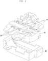
- FIG. 1 schematically illustrates a structure of a general ear jack socket.
- the ear jack socket includes an integral socket body 10 into which an ear jack plug (not illustrated) is inserted, contact terminals 20 electrically connecting the plug to a circuit board of the portable terminal, and a cover 30 enclosing the socket body 10.
- the integral socket body 10 should have large holes such that the contact terminals 20 having different shapes and structures at upper and lower sides thereof may be coupled to the socket body 10.
- an upper portion 22 of the contact terminal 20 has a small size since it protrudes to the outside of the socket body 10 and contacts the circuit board of the portable terminal, whereas a lower portion 24 of the contact terminal 20 has a relatively large size since it includes a protrusion area facing the plug inserted into the socket body 10 to contact the plug.
- the size of the contact terminal 20 refers to, for example, a volume of the contact terminal 20.
- a hole 40 corresponding to the size of the lower portion 24 of the contact terminal 24 should be formed on one surface of the socket body 10.
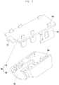
- FIG. 2 schematically illustrates a separable socket body of an ear jack socket for a portable terminal in accordance with embodiments of the present disclosure.
- a separable socket body 135 of an ear jack socket for a portable terminal in accordance with the embodiments of the present disclosure includes an upper socket 110 and a lower socket 130.
- the upper socket 110 and the lower socket 130 may be formed of at least one of heat-resistant plastic, Polycarbonate (PC), Polyethylene Terephthalate Glycol (PETG), polyethylene (PE), and polypropylene (PP), and may be molded through at least one process of extrusion, blow molding, injection molding, compression, and vacuum forming.
- PC Polycarbonate
- PETG Polyethylene Terephthalate Glycol
- PE polyethylene
- PP polypropylene
- the upper socket 110 has a dome shape at an entrance portion 112 thereof along an outer circumference of an ear jack plug.
- the entrance portion 112 for insertion of the ear jack plug is a portion of a plug insertion hole.
- a plurality of slits 114 for coupling contact terminals 140 to the upper socket 110 later are formed on one surface of the upper socket 110 spaced apart from each other by a predetermined separation.
- the slits 114 have the form of holes through which the contact terminals 140 pass through the upper socket 110 and have appropriate sizes for attachment to and engagement with the contact terminals 140.
- One surface of the lower socket 130 is formed to be coupled to the upper socket 110 while facing the upper socket 110, and a portion 132 of the plug insertion hole for insertion of the ear phone plug is formed on a side surface of the lower socket 130.
- a plurality of recesses 134 corresponding to the slits 114 formed on one surface of the upper socket 110 are formed on one surface of the lower socket 130 facing the socket 110.
- the recesses 134 are formed such that the contact terminals 140 can be vertically inserted into the slits 114 and the recesses 134 at the same time and the contact terminals 140 can be attached to and engaged with the recesses 134. That is, the contact terminals 140 having passed through the slits 114 can be attached to and engaged with the recesses 134.
- the upper socket 110 and the lower socket 130 of the socket body 135 are individually injection molded, and the slits 114 and the recesses 134 are formed such that the contact terminals 140 inserted into the upper socket 110 and the lower socket 130 at the same time can be attached to and engaged with the slits 114 and the recesses 134 according to the different shapes of the contact terminals 140, so that a gap is actually not generated between the socket 135 and the contact terminals 140.
- the contact terminals 140 are attached and inserted into the upper socket 110 and the lower socket 130, by reducing the sizes of external holes, moisture can be prevented from penetrating into the portable terminal even when moisture penetrates through the ear jack socket.
- the portion 132 of the plug insertion hole of the lower socket 130 is coupled to a portion of the plug insertion hole formed at the entrance portion 112 of the upper socket 110 to completely form a plug insertion hole (see reference number 510 of FIG. 5 ).
- the plug insertion hole (see reference number 510 of FIG. 5 ) can be closed by a separate lid, and can be opened by detaching the lid if necessary.
- FIG. 3 illustrates perspective views of a process of coupling the separable socket body of the ear jack socket for a portable terminal in accordance with the embodiments of the present disclosure.
- the separable socket body 135 of the ear jack socket for a portable terminal in accordance with the embodiments of the present disclosure is formed by coupling the upper socket 110 and the lower socket 130 of the separable socket body 135, by assembling the contact terminals 140 in the slits 114 and the recesses 134 facing the slits 114, and by bonding the upper socket 110 and the lower socket 130.
- sizes of holes for insertion of the contact terminals 140 can be reduced as compared with those of the socket body in FIG. 1 by individually injection molding the upper socket 110 and the lower socket 130, and by attaching and inserting the contact terminals 140 into the upper socket 110 and the lower socket 130. That is, since the slits 114 are formed to correspond to the sizes and shapes of the contact terminals 140, a gap is not generated between the contact terminals 140 and the socket body 135 due to the differences between the sizes and shapes thereof.
- the contact terminals 140 are terminals for transmitting and receiving audio signals when the ear jack plug is coupled to the ear jack socket. That is, the contact terminals 140 are interfaces for communications between the circuit board of the portable terminal and the ear jack plug. For example, the contact terminals provide paths for transmitting a signal transmitted from an ear microphone of the ear phone to the circuit board. Also, the contact terminals 140 provide paths for transmitting a function sound, an effect sound, and a reception sound generated in the circuit board to the ear jack plug.
- an upper portion of the contact terminal 140 passing through the corresponding slit 114 and protruding upwards extends to the inside of the portable terminal can electrically contact the printed circuit board (PCB).
- PCB printed circuit board
- a flexible printed circuit board or wiring such as a connection wire can be used.
- the portions where the contact terminals 140 and the slits 114 contact each other and the portions where the contact terminals 140 and the recesses 134 contact each other can be bonded by using an adhesive or double-sided tapes to reinforce bonding forces.
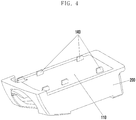
- FIG. 4 schematically illustrates a structure in which a waterproof cover is injection molded together with the separable socket body of the ear jack socket for a portable terminal in accordance with an embodiment of the present disclosure.
- FIG. 5 schematically illustrates the waterproof cover according to the embodiment of the present disclosure.
- the socket body 135 formed by assembling the upper socket 110 and the lower socket 130 and by engaging the contact terminals 140 is injection molded around to form the waterproof cover 200. That is, the waterproof cover 200 is attached to the socket body 135 by placing the socket body 135 into a mold in advance and by injection molding around the socket body 135.
- the waterproof cover 200 encloses the socket body 135, and can prevent the socket body 135 from being contaminated or damaged by an external environment and can prevent water from penetrating into the interior of the portable terminal from the outside.
- the waterproof cover 200 covers the socket body 135 except for the upper body 110 in which the contact terminals 140 pass through the slits 114 to be exposed to the outside, and the plug insertion hole 510 into which the ear jack plug is inserted, but the structure of the waterproof cover 200 is not limited thereto.
- the waterproof cover 200 can be formed by inserting injection molding around the socket body 135 with liquid silicon rubber.
- An adhesive such as a primer can be applied on an outer surface of the socket body 135 to further increase attachment performance of the waterproof cover 200 and the socket body 135.
- an adhesive can be further added to the liquid silicon rubber.
- the integral ear jack socket is formed through the injection molding.
- a circumference of the waterproof cover 200 adjacent to the plug insertion hole 510 further includes a convex portion 220 protruding by a predetermined height with respect to a surface of the waterproof cover 200.
- the convex portion 220 is formed of a resilient material such as silicon rubber.
- the convex portion 220 is attached to an inner wall of the portable terminal by a resilient force while the waterproof cover 200 is mounted within the portable terminal, it can separate the socket body 135 from the outside and thus prevent moisture from being introduced into the socket body 135 when the portable terminal is submerged in water.
- the convex portion 220 is formed along a circumference of the plug insertion hole 510 and can be formed to partially cover an outer surface of the lower socket 130 of the socket body 135.
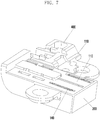
- FIG. 6 illustrates a structure in which the waterproof cover is bonded to the separable socket body of the ear jack socket for a portable terminal in accordance with embodiments of the present disclosure.
- FIG. 7 illustrates a structure of the ear jack socket of FIG. 6 when viewed from the rear side.
- FIGS. 8 and 9 schematically illustrate a structure in which the ear jack socket is mounted within a portable terminal in accordance with the embodiment of the present disclosure.
- the socket body 135 covered by the waterproof cover 200 as illustrated in FIGS. 6 and 7 is mounted to an interior of the portable terminal 300 as illustrated in FIG. 9 .
- An entrance of the plug insertion hole 510 is mounted to be exposed to the outside.
- the socket body 135 is injection molded around and is provided with the plug insertion hole 510 for insertion of the ear jack plug.
- the contact terminals 140 contacting the ear jack plug to transfer an electrical signal to an internal circuit of the portable terminal, but as illustrated in FIGS. 6 and 7 , may be injection molded while a structure 400 for mounting other component elements in the portable terminal extends from a portion of the socket body 135.
- the socket body 135 in the case where the socket body 135 is submerged in water, the socket body 135 can primarily prevent moisture from penetrating into the portable terminal 300 due to the attachment of the convex portion 220 and an inner wall of the portable terminal 300, and can secondarily prevent moisture from penetrating into the portable terminal 300 by individually injection molding the upper socket 110 and the lower socket 130, attaching and inserting the contact terminals 140 into the upper socket 110 and the lower socket 130, and accordingly reducing a size of an external hole.
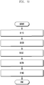
- FIG. 10 illustrates a process of manufacturing a waterproof ear jack socket in accordance with an embodiment of the present disclosure.
- the upper socket 110 and the lower socket 130 for forming the socket body 135 having the plug insertion hole 510 into which the ear jack plug is inserted are individually injection molded.
- the upper socket 110 and the lower socket 130 can be formed of at least one of heat-resistant plastic, Polycarbonate (PC), Polyethylene Terephthalate Glycol (PETG), polyethylene (PE), and polypropylene (PP), and can be molded through at least one process of extrusion, blow molding, injection molding, compression, and vacuum forming.
- the upper socket 110 has a dome shape at the entrance portion 112 thereof along an outer circumference of an ear jack plug.
- the entrance portion 112 for insertion of the ear jack plug is a portion of a plug insertion hole 510.
- At least one slit 114 is formed on one surface of the upper socket 110 such that a first portion of the contact terminal 140 can pass through the surface of the upper socket 110 to be exposed to the outside. Also, a recess for engaging a second portion 141 of the contact terminal is formed on one surface of the lower socket 130 facing the upper socket 110. Two or more slits 114 are spaced apart from each other by a predetermined separation in the form of a hole through which the contact terminal 140 passes, and have a size for attachment to and engagement with the contact terminal 140.
- the second portion 141 of the contact terminal is engaged with and assembled in the recess 134 by inserting the first portion 140 of the contact terminal 240 into the slit 114.
- the socket body 135 is formed by bonding the upper socket 110 and the lower socket 130.
- the upper body 110 and the lower body 130 are bonded to each other by using a double-sided tape or an adhesive, but the present disclosure is not limited thereto.
- the waterproof cover 200 is formed by insert injection molding around the socket body 135. That is, the socket body 135 is placed into the mold in advance to be insert injection molded around so that the waterproof cover 200 is attached to the socket body 135.
- the waterproof cover 200 prevents the socket body 135 from being contaminated or damaged by an external environment while enclosing the socket body 135 and can prevent water from penetrating into the portable terminal from the outside at the same time.
- the waterproof cover 200 covers the socket body 135 except for the upper socket 110 in which the contact terminals 140 pass through the slits 114 to be exposed and except for the plug insertion hole 510 into which the ear jack plug is inserted, but the present disclosure is not limited the structure.
- the waterproof cover 200 can be formed by inserting injection molding around the socket body 135 with liquid silicon rubber.
- An adhesive such as a primer is applied on an outer surface of the socket body 135 to further increase attachment performance of the waterproof cover 200 and the socket body 135.
- An adhesive can be further added to the liquid silicon rubber.
- the integral ear jack socket can be formed through the injection molding.
- a circumference of the waterproof cover 200 adjacent to the plug insertion hole 510 can further have a resilient structure protruding by a predetermined height to be attached to the inner wall of the portable terminal by a resilient force, thereby enhancing a waterproof effect.
- the socket body can primarily prevent moisture from penetrating into the portable terminal by separating the inner wall of the portable terminal and the ear jack socket structure from the outside, and can secondarily prevent moisture from penetrating into the portable terminal by individually injection molding the upper socket and the lower socket, attaching and inserting the contact terminals into the upper socket and the lower socket, and accordingly reducing a size of an external hole.
Landscapes
- Engineering & Computer Science (AREA)
- Manufacturing & Machinery (AREA)
- Signal Processing (AREA)
- Connector Housings Or Holding Contact Members (AREA)
- Coupling Device And Connection With Printed Circuit (AREA)
- Headphones And Earphones (AREA)
- Telephone Set Structure (AREA)
Description
- The present disclosure relates to a waterproof ear jack socket and a method of manufacturing the same, and more particularly, to a waterproof ear jack socket that is provided with a waterproof function to prevent water from penetrating into a portable terminal, and a method of manufacturing the same.
- A portable terminal refers to a device carried by a user, and provides a communication function, an electronic note function, a multimedia function, and a broadcast receiving function.
- Such a portable terminal generally includes various sockets and connectors for connection to an external speaker and an earphone, connection to an external device such as a personal computer, and mounting of a memory or a SIM card.
- The sockets or connectors are generally exposed to the outside as a user connects an earphone or an interface connector to the sockets or connectors if necessary, and include separate covers so that foreign substances cannot be introduced through the sockets or connectors.
- Meanwhile, as portable terminals are commonly used, a waterproof function of the portable terminals is gradually gaining interest. Users of portable terminals generally purchase separate waterproof bags if necessary. That is, as long as the waterproof function of portable terminals is not required in everyday lives, users of the portable terminals prevent water penetration of the portable terminals by using waterproof bags only when entering specific facilities. Meanwhile, mountain climbers, soldiers, and people who enjoy aquatic sports or skiing need the waterproof function of portable terminals more.
- This is because such users are generally easily exposed to sudden weather changes or bad situations, such that water may possibly penetrate into the portable terminals.
-
CN 202 737 215 U discloses an audio frequency socket connector comprising a main body part and a shielding housing. The insulator body group comprises an insulator body and a plurality of contact terminals inserted in the insulator bodies. -
JP 2012 014863 A -
CN 202 633 641 U discloses an audio socket connector having an insulating body, a plurality of terminals, a waterproof board and a waterproof pedestal. - To address the above-discussed deficiencies, it is a primary object to provide an ear jack socket that prevents water penetration into a portable terminal and a method of manufacturing the same.
- Various respective aspects and features of the invention are defined in the appended claims.
- The features and technical advantages of the present disclosure will be somewhat widely described so that those skilled in the art to which the present disclosure pertains can easily understand the contents of the present disclosure from a detailed description of the present disclosure. In addition to the features and advantages, the additional features and technical advantages defining the subject of the claims of the present disclosure will be understood more clearly from the detailed description of the present disclosure.
- According to a first aspect of the present invention there is provided a waterproof ear jack socket for a portable terminal comprising: an upper socket having at least one slit formed to allow passage of a first portion of a contact terminal through one surface of the upper socket to be exposed to the outside wherein the at least one slit has an appropriate size for attachment to and engagement with the contact terminal; a lower socket having a recess configured to engage a second portion of the contact terminal on one surface thereof facing the upper socket, the lower socket being coupled to the upper socket to form a plug insertion hole into which an ear jack plug can be inserted, wherein the upper socket and the lower socket define separate parts of the entrance portion of the plug insertion hole; and a waterproof cover formed by insert injection molding around a socket body formed by bonding the upper socket and the lower socket and configured to prevent the socket body from being contaminated or damaged by an external environment; wherein the waterproof cover has a convex portion formed to protrude by a predetermined height at a circumference adjacent to an entrance portion of the plug insertion hole and wherein the convex portion is configured to attach to an inner wall of a terminal by a resilient force and is formed of a resilient material.
- According to a second aspect of the present invention there is provided a method of manufacturing a waterproof ear jack socket for a portable terminal, the method comprising: individually injection molding an upper socket and a lower socket for forming a socket body having a plug insertion hole into which an ear jack plug is to be inserted, wherein the upper socket and the lower socket define separate parts of the entrance portion of the plug insertion hole; forming at least one slit on one surface of the upper socket such that a first portion of a contact terminal passes through the surface of the upper socket to be exposed to the outside wherein the at least one slit has an appropriate size for attachment to and engagement with the contact terminal and forming a recess for engaging an second portion of the contact terminal on one surface of the lower socket facing the upper socket; assembling the contact terminal such that the first portion of the contact terminal is inserted into the slit and the second portion of the contact terminal is engaged with the recess; bonding the upper socket and the lower socket to form the socket body; and inserting injection molding around the socket body to form a waterproof cover having a convex portion formed to protrude by a predetermined height at a circumference adjacent to an entrance portion of the plug insertion hole and configured to prevent the socket body from being contaminated or damaged by an external environment.
- Before undertaking the DETAILED DESCRIPTION below, it may be advantageous to set forth definitions of certain words and phrases used throughout this patent document: the terms "include" and "comprise," as well as derivatives thereof, mean inclusion without limitation; the term "or," is inclusive, meaning and/or; the phrases "associated with" and "associated therewith," as well as derivatives thereof, may mean to include, be included within, interconnect with, contain, be contained within, connect to or with, couple to or with, be communicable with, cooperate with, interleave, juxtapose, be proximate to, be bound to or with, have, have a property of, or the like; and the term "controller" means any device, system or part thereof that controls at least one operation, such a device may be implemented in hardware, firmware or software, or some combination of at least two of the same. It should be noted that the functionality associated with any particular controller may be centralized or distributed, whether locally or remotely. Definitions for certain words and phrases are provided throughout this patent document, those of ordinary skill in the art should understand that in many, if not most instances, such definitions apply to prior, as well as future uses of such defined words and phrases.
- For a more complete understanding of the present disclosure and its advantages, reference is now made to the following description taken in conjunction with the accompanying drawings, in which like reference numerals represent like parts:
-
FIG. 1 schematically illustrates a structure of a general ear jack socket; -
FIG. 2 illustrates schematic views of a structure of a separable socket body of an ear jack socket for a portable terminal in accordance with embodiments of the present disclosure; -
FIG. 3 illustrates perspective views of a process of coupling the separable socket body of the ear jack socket for a portable terminal in accordance with embodiments of the present disclosure; -
FIG. 4 schematically illustrates a structure in which a waterproof cover is injection molded together with the separable socket body of the ear jack socket for a portable terminal in accordance with embodiments of the present disclosure; -
FIG. 5 schematically illustrates a waterproof cover according to embodiments of the present disclosure; -
FIG. 6 illustrates a structure in which the waterproof cover is bonded to the separable socket body of the ear jack socket for a portable terminal in accordance with embodiments of the present disclosure; -
FIG. 7 illustrates a structure of the ear jack socket ofFIG. 6 when viewed from the rear side; -
FIGS. 8 and9 schematically illustrate a structure in which the ear jack socket is mounted within a portable terminal in accordance with embodiments of the present disclosure; and -
FIG. 10 illustrates a process of manufacturing a waterproof ear jack socket in accordance with embodiments of the present disclosure. -
FIGURES 1 through 10 , discussed below, and the various embodiments used to describe the principles of the present disclosure in this patent document are by way of illustration only and should not be construed in any way to limit the scope of the disclosure. Those skilled in the art will understand that the principles of the present disclosure may be implemented in any suitably arranged wireless communication device. Hereinafter, embodiments of the present disclosure will be described in detail with reference to the accompanying drawings. It is noted that in the drawings, the same elements are provided with the same reference numerals if possible. Further, a detailed description of a configuration of the present disclosure may be omitted herein when it may make the essence of the present disclosure obscure. - In the embodiments of the present disclosure, a portable terminal may apply to all information communication devices and multimedia devices such as a tablet PC, a mobile communication terminal, a mobile phone, a Personal Digital Assistant (PDA), a smart phone, an International Mobile Telecommunication 2000 (IMT-2000) terminal, a Code Division Multiple Access (CDMA) terminal, a Wideband Code Division Multiple Access (WCDMA) terminal, a Global System for Mobile communication (GSM) terminal, a General Packet Radio Service (GPRS) terminal, an Enhanced Data for GSM Evolution (EDGE) terminal, a Universal Mobile Telecommunication Service (UMTS) terminal, a digital broadcasting terminal, and an Automated Teller Machine (ATM), and applications thereof.
-
FIG. 1 schematically illustrates a structure of a general ear jack socket. - Referring to
FIG. 1 , the ear jack socket includes anintegral socket body 10 into which an ear jack plug (not illustrated) is inserted,contact terminals 20 electrically connecting the plug to a circuit board of the portable terminal, and acover 30 enclosing thesocket body 10. - In the ear jack socket of
FIG. 1 , theintegral socket body 10 should have large holes such that thecontact terminals 20 having different shapes and structures at upper and lower sides thereof may be coupled to thesocket body 10. - Referring to the exploded view of
FIG. 1 illustrating thecontact terminal 20, in general, anupper portion 22 of thecontact terminal 20 has a small size since it protrudes to the outside of thesocket body 10 and contacts the circuit board of the portable terminal, whereas a lower portion 24 of thecontact terminal 20 has a relatively large size since it includes a protrusion area facing the plug inserted into thesocket body 10 to contact the plug. The size of thecontact terminal 20 refers to, for example, a volume of thecontact terminal 20. - In order to mount the
contact terminal 20 having different sizes at the upper andlower portions 22 and 24 thereof to theintegral socket body 10, a hole 40 corresponding to the size of the lower portion 24 of the contact terminal 24 should be formed on one surface of thesocket body 10. - However, even if the
contact terminal 20 can be mounted all at once through the hole 40 corresponding to the size of the lower portion 24 of thecontact terminal 20, a gap may be generated due to the differences in the shapes and sizes of the hole 40 and theupper portion 22 of thecontact terminal 20. - Since an interior of the
socket body 10 may be exposed to the outside through the gap, water may penetrate into the portable terminal as well as into thesocket body 10 through the gap when the portable terminal is submerged in water. -
FIG. 2 schematically illustrates a separable socket body of an ear jack socket for a portable terminal in accordance with embodiments of the present disclosure. - Referring to
FIG. 2 , aseparable socket body 135 of an ear jack socket for a portable terminal in accordance with the embodiments of the present disclosure includes anupper socket 110 and alower socket 130. - The
upper socket 110 and thelower socket 130 may be formed of at least one of heat-resistant plastic, Polycarbonate (PC), Polyethylene Terephthalate Glycol (PETG), polyethylene (PE), and polypropylene (PP), and may be molded through at least one process of extrusion, blow molding, injection molding, compression, and vacuum forming. - The
upper socket 110 has a dome shape at anentrance portion 112 thereof along an outer circumference of an ear jack plug. Theentrance portion 112 for insertion of the ear jack plug is a portion of a plug insertion hole. - A plurality of
slits 114 forcoupling contact terminals 140 to theupper socket 110 later are formed on one surface of theupper socket 110 spaced apart from each other by a predetermined separation. In certain embodiments, theslits 114 have the form of holes through which thecontact terminals 140 pass through theupper socket 110 and have appropriate sizes for attachment to and engagement with thecontact terminals 140. - One surface of the
lower socket 130 is formed to be coupled to theupper socket 110 while facing theupper socket 110, and aportion 132 of the plug insertion hole for insertion of the ear phone plug is formed on a side surface of thelower socket 130. - A plurality of
recesses 134 corresponding to theslits 114 formed on one surface of theupper socket 110 are formed on one surface of thelower socket 130 facing thesocket 110. - The
recesses 134 are formed such that thecontact terminals 140 can be vertically inserted into theslits 114 and therecesses 134 at the same time and thecontact terminals 140 can be attached to and engaged with therecesses 134. That is, thecontact terminals 140 having passed through theslits 114 can be attached to and engaged with therecesses 134. - In accordance with the embodiments of the present disclosure, the
upper socket 110 and thelower socket 130 of thesocket body 135 are individually injection molded, and theslits 114 and therecesses 134 are formed such that thecontact terminals 140 inserted into theupper socket 110 and thelower socket 130 at the same time can be attached to and engaged with theslits 114 and therecesses 134 according to the different shapes of thecontact terminals 140, so that a gap is actually not generated between thesocket 135 and thecontact terminals 140. - That is, in accordance with the embodiments of the present disclosure, since the
contact terminals 140 are attached and inserted into theupper socket 110 and thelower socket 130, by reducing the sizes of external holes, moisture can be prevented from penetrating into the portable terminal even when moisture penetrates through the ear jack socket. - When the
upper socket 110 and thelower socket 130 are coupled to each other, theportion 132 of the plug insertion hole of thelower socket 130 is coupled to a portion of the plug insertion hole formed at theentrance portion 112 of theupper socket 110 to completely form a plug insertion hole (seereference number 510 ofFIG. 5 ). - The plug insertion hole (see
reference number 510 ofFIG. 5 ) can be closed by a separate lid, and can be opened by detaching the lid if necessary. -
FIG. 3 illustrates perspective views of a process of coupling the separable socket body of the ear jack socket for a portable terminal in accordance with the embodiments of the present disclosure. - Referring to
FIG. 3 , theseparable socket body 135 of the ear jack socket for a portable terminal in accordance with the embodiments of the present disclosure is formed by coupling theupper socket 110 and thelower socket 130 of theseparable socket body 135, by assembling thecontact terminals 140 in theslits 114 and therecesses 134 facing theslits 114, and by bonding theupper socket 110 and thelower socket 130. - It can be seen that in accordance with the embodiments of the present disclosure, sizes of holes for insertion of the
contact terminals 140 can be reduced as compared with those of the socket body inFIG. 1 by individually injection molding theupper socket 110 and thelower socket 130, and by attaching and inserting thecontact terminals 140 into theupper socket 110 and thelower socket 130. That is, since theslits 114 are formed to correspond to the sizes and shapes of thecontact terminals 140, a gap is not generated between thecontact terminals 140 and thesocket body 135 due to the differences between the sizes and shapes thereof. - The
contact terminals 140 are terminals for transmitting and receiving audio signals when the ear jack plug is coupled to the ear jack socket. That is, thecontact terminals 140 are interfaces for communications between the circuit board of the portable terminal and the ear jack plug. For example, the contact terminals provide paths for transmitting a signal transmitted from an ear microphone of the ear phone to the circuit board. Also, thecontact terminals 140 provide paths for transmitting a function sound, an effect sound, and a reception sound generated in the circuit board to the ear jack plug. - For this function, an upper portion of the
contact terminal 140 passing through thecorresponding slit 114 and protruding upwards extends to the inside of the portable terminal can electrically contact the printed circuit board (PCB). Thereto, a flexible printed circuit board or wiring such as a connection wire can be used. - A
lower portion 141 of thecontact terminal 140 exposed through a hole 138 formed in an inner wall of thecorresponding recess 134 electrically contacts the ear jack plug. That is, the ear jack plug and the exposed portions of thecontact terminals 140 directly contact each other through the holes 138 formed in the inner walls of therecesses 134 to be spaced apart from each other. Accordingly, the ear jack plug and an internal circuit of the portable terminal can be electrically connected to each other. - The portions where the
contact terminals 140 and theslits 114 contact each other and the portions where thecontact terminals 140 and therecesses 134 contact each other can be bonded by using an adhesive or double-sided tapes to reinforce bonding forces. -
FIG. 4 schematically illustrates a structure in which a waterproof cover is injection molded together with the separable socket body of the ear jack socket for a portable terminal in accordance with an embodiment of the present disclosure.FIG. 5 schematically illustrates the waterproof cover according to the embodiment of the present disclosure. - Referring to
FIGS. 4 and5 , thesocket body 135 formed by assembling theupper socket 110 and thelower socket 130 and by engaging thecontact terminals 140 is injection molded around to form thewaterproof cover 200. That is, thewaterproof cover 200 is attached to thesocket body 135 by placing thesocket body 135 into a mold in advance and by injection molding around thesocket body 135. - The
waterproof cover 200 encloses thesocket body 135, and can prevent thesocket body 135 from being contaminated or damaged by an external environment and can prevent water from penetrating into the interior of the portable terminal from the outside. - The
waterproof cover 200 covers thesocket body 135 except for theupper body 110 in which thecontact terminals 140 pass through theslits 114 to be exposed to the outside, and theplug insertion hole 510 into which the ear jack plug is inserted, but the structure of thewaterproof cover 200 is not limited thereto. - The
waterproof cover 200 can be formed by inserting injection molding around thesocket body 135 with liquid silicon rubber. An adhesive such as a primer can be applied on an outer surface of thesocket body 135 to further increase attachment performance of thewaterproof cover 200 and thesocket body 135. an adhesive can be further added to the liquid silicon rubber. The integral ear jack socket is formed through the injection molding. - Referring to
FIGS. 5 and6 , a circumference of thewaterproof cover 200 adjacent to theplug insertion hole 510 further includes aconvex portion 220 protruding by a predetermined height with respect to a surface of thewaterproof cover 200. Theconvex portion 220 is formed of a resilient material such as silicon rubber. - Since the
convex portion 220 is attached to an inner wall of the portable terminal by a resilient force while thewaterproof cover 200 is mounted within the portable terminal, it can separate thesocket body 135 from the outside and thus prevent moisture from being introduced into thesocket body 135 when the portable terminal is submerged in water. - The
convex portion 220 is formed along a circumference of theplug insertion hole 510 and can be formed to partially cover an outer surface of thelower socket 130 of thesocket body 135. -
FIG. 6 illustrates a structure in which the waterproof cover is bonded to the separable socket body of the ear jack socket for a portable terminal in accordance with embodiments of the present disclosure.FIG. 7 illustrates a structure of the ear jack socket ofFIG. 6 when viewed from the rear side.FIGS. 8 and9 schematically illustrate a structure in which the ear jack socket is mounted within a portable terminal in accordance with the embodiment of the present disclosure. - The
socket body 135 covered by thewaterproof cover 200 as illustrated inFIGS. 6 and7 is mounted to an interior of theportable terminal 300 as illustrated inFIG. 9 . An entrance of theplug insertion hole 510 is mounted to be exposed to the outside. - The
socket body 135 is injection molded around and is provided with theplug insertion hole 510 for insertion of the ear jack plug. Thecontact terminals 140 contacting the ear jack plug to transfer an electrical signal to an internal circuit of the portable terminal, but as illustrated inFIGS. 6 and7 , may be injection molded while astructure 400 for mounting other component elements in the portable terminal extends from a portion of thesocket body 135. - As illustrated in
FIG. 8 and9 , in the case where thesocket body 135 is submerged in water, thesocket body 135 can primarily prevent moisture from penetrating into theportable terminal 300 due to the attachment of theconvex portion 220 and an inner wall of theportable terminal 300, and can secondarily prevent moisture from penetrating into theportable terminal 300 by individually injection molding theupper socket 110 and thelower socket 130, attaching and inserting thecontact terminals 140 into theupper socket 110 and thelower socket 130, and accordingly reducing a size of an external hole. -
FIG. 10 illustrates a process of manufacturing a waterproof ear jack socket in accordance with an embodiment of the present disclosure. - Referring to
FIGS. 10 and2 to 5 , first, in block S110, theupper socket 110 and thelower socket 130 for forming thesocket body 135 having theplug insertion hole 510 into which the ear jack plug is inserted are individually injection molded. Theupper socket 110 and thelower socket 130 can be formed of at least one of heat-resistant plastic, Polycarbonate (PC), Polyethylene Terephthalate Glycol (PETG), polyethylene (PE), and polypropylene (PP), and can be molded through at least one process of extrusion, blow molding, injection molding, compression, and vacuum forming. Theupper socket 110 has a dome shape at theentrance portion 112 thereof along an outer circumference of an ear jack plug. Theentrance portion 112 for insertion of the ear jack plug is a portion of aplug insertion hole 510. - Next, in block S130, at least one
slit 114 is formed on one surface of theupper socket 110 such that a first portion of thecontact terminal 140 can pass through the surface of theupper socket 110 to be exposed to the outside. Also, a recess for engaging asecond portion 141 of the contact terminal is formed on one surface of thelower socket 130 facing theupper socket 110. Two ormore slits 114 are spaced apart from each other by a predetermined separation in the form of a hole through which thecontact terminal 140 passes, and have a size for attachment to and engagement with thecontact terminal 140. - Next, in clock S150, the
second portion 141 of the contact terminal is engaged with and assembled in therecess 134 by inserting thefirst portion 140 of the contact terminal 240 into theslit 114. - Next, in block S170, the
socket body 135 is formed by bonding theupper socket 110 and thelower socket 130. Theupper body 110 and thelower body 130 are bonded to each other by using a double-sided tape or an adhesive, but the present disclosure is not limited thereto. - Next, in block S190, the
waterproof cover 200 is formed by insert injection molding around thesocket body 135. That is, thesocket body 135 is placed into the mold in advance to be insert injection molded around so that thewaterproof cover 200 is attached to thesocket body 135. Thewaterproof cover 200 prevents thesocket body 135 from being contaminated or damaged by an external environment while enclosing thesocket body 135 and can prevent water from penetrating into the portable terminal from the outside at the same time. Thewaterproof cover 200 covers thesocket body 135 except for theupper socket 110 in which thecontact terminals 140 pass through theslits 114 to be exposed and except for theplug insertion hole 510 into which the ear jack plug is inserted, but the present disclosure is not limited the structure. - The
waterproof cover 200 can be formed by inserting injection molding around thesocket body 135 with liquid silicon rubber. An adhesive such as a primer is applied on an outer surface of thesocket body 135 to further increase attachment performance of thewaterproof cover 200 and thesocket body 135. An adhesive can be further added to the liquid silicon rubber. The integral ear jack socket can be formed through the injection molding. - In particular, a circumference of the
waterproof cover 200 adjacent to theplug insertion hole 510 can further have a resilient structure protruding by a predetermined height to be attached to the inner wall of the portable terminal by a resilient force, thereby enhancing a waterproof effect. - Accordingly, in the case where the socket body is submerged in water, the socket body can primarily prevent moisture from penetrating into the portable terminal by separating the inner wall of the portable terminal and the ear jack socket structure from the outside, and can secondarily prevent moisture from penetrating into the portable terminal by individually injection molding the upper socket and the lower socket, attaching and inserting the contact terminals into the upper socket and the lower socket, and accordingly reducing a size of an external hole.
- Although the present disclosure has been described with embodiments, various changes and modifications may be suggested to one skilled in the art. It is intended that the present disclosure encompass such changes and modifications as fall within the scope of the appended claims.
Claims (14)
- A waterproof ear jack socket for a portable terminal comprising:an upper socket (110) having at least one slit (114) formed to allow passage of a first portion of a contact terminal (140) through one surface of the upper socket (110) to be exposed to the outside wherein the at least one slit has an appropriate size for attachment to and engagement with the contact terminal (140);a lower socket (130) having a recess (134) configured to engage a second portion of the contact terminal (140) on one surface thereof facing the upper socket, the lower socket being coupled to the upper socket to form a plug insertion hole (510) into which an ear jack plug can be inserted; anda waterproof cover (200) formed by insert injection molding around a socket body (135) formed by bonding the upper socket and the lower socket and configured to prevent the socket body (135) from being contaminated or damaged by an external environment;the waterproof ear jack socket being characterized in that the upper socket (110) and the lower socket (130) define separate parts of the entrance portion of the plug insertion hole (510) and in that the waterproof cover (200) has a convex portion (220) formed to protrude by a predetermined height at a circumference adjacent to an entrance portion (112, 132) of the plug insertion hole (510) and wherein the convex portion (220) is configured to attach to an inner wall of a portable terminal (300), within which the ear jack socket is mounted, by a resilient force and is formed of a resilient material.
- The waterproof ear jack socket of claim 1, wherein the upper socket (110) has a structure configured to allow passage of the first portion of the contact terminal through the slit (114) while being attached to the slit (114).
- The waterproof ear jack socket of claim 1, wherein the lower socket (130) has a structure in which the second portion of the contact terminal is configured to attach to and engage with the recess (134).
- The waterproof ear jack socket of claim 1, wherein the upper socket (110) and the lower socket (130) are bonded to each other by one of: a double-sided tape and an adhesive.
- The waterproof ear jack socket of claim 1, wherein the waterproof cover (200) is formed of liquid silicon rubber.
- The waterproof ear jack socket of claim 1, wherein the recess (134) has a hole (138) configured to connect a portion of the inner wall of the lower socket (130) to the plug insertion hole (510).
- A waterproof ear jack socket according to claim 1, wherein:the socket body in which the upper socket and the lower socket are separately manufactured are coupled to each other to form the plug insertion hole (510) into which an ear jack plug can be inserted on a side surface thereof;the waterproof cover enclosing the socket body and in which the convex resilient portion of a surface of the waterproof cover corresponding to a circumference of an entrance of the plug insertion hole (510) protrudes to be attached to an inner wall of a terminal by a resilient force; anda contact terminal comprising the first contact terminal passing through at least one hole formed on an upper surface of the upper socket to be connected to a circuit board of a terminal, and the lower contact terminal is integrally formed with the upper contact terminal and configured for insertion into the recess formed in the lower socket to enable contact with the ear jack plug
- The waterproof ear jack socket of claim 7, wherein the upper contact terminal is configured to pass through the hole of the upper socket (110) while being attached to an inner wall of the hole and the lower contact terminal is configured to insert into the recess (134) of the lower socket (130) while being attached to an inner wall of the recess.
- The waterproof ear jack socket of claim 7, wherein the upper contact terminal and the lower contact terminal of the contact terminal (140) have different sizes.
- The waterproof ear jack socket of claim 7, wherein the waterproof cover is configured to attach to the socket body except for an upper surface of the upper socket and an entrance of the plug insertion hole (510).
- A method of manufacturing a waterproof ear jack socket for a portable terminal, the method comprising:individually injection molding (S110) an upper socket and a lower socket for forming a socket body having a plug insertion hole (510) into which an ear jack plug is to be inserted;forming (S130) at least one slit on one surface of the upper socket such that a first portion of a contact terminal passes through the surface of the upper socket to be exposed to the outside wherein the at least one slit has an appropriate size for attachment to and engagement with the contact terminal and forming a recess for engaging a second portion of the contact terminal on one surface of the lower socket facing the upper socket;assembling (S150) the contact terminal such that the first portion of the contact terminal is inserted into the slit and the second portion of the contact terminal is engaged with the recess;bonding (S170) the upper socket and the lower socket to form the socket body; the method being characterized in that the upper socket (110) and the lower socket (130) define separate parts of the entrance portion of the plug insertion hole (510) and ininserting (S190) injection molding around the socket body to form a waterproof cover having a convex portion (220) formed to protrude by a predetermined height at a circumference adjacent to an entrance portion (112, 132) of the plug insertion hole (510) and configured to prevent the socket body from being contaminated or damaged by an external environment when the ear jack socket is mounted within a portable terminal.
- The method of claim 11, wherein in the forming of the waterproof cover, the socket body is injection molded around such that the waterproof cover is attached to an outer circumference of the socket body except for the plug insertion hole (510) and one surface of the upper socket from which the contact terminal is exposed, wherein the waterproof cover is formed by inserting injection molding around the socket body with liquid silicon rubber.
- The method of claim 12, wherein the forming of the waterproof cover comprises applying a primer on a surface of the socket body before the waterproof cover is injection molded.
- The method of claim 11, wherein the forming of the waterproof cover further comprises forming a convex portion at a circumference of the waterproof cover adjacent to the plug insertion hole to separate a space of an inner wall of a terminal and the waterproof cover from the outside.
Applications Claiming Priority (1)
| Application Number | Priority Date | Filing Date | Title |
|---|---|---|---|
| KR1020130027171A KR102042727B1 (en) | 2013-03-14 | 2013-03-14 | Waterproof ear jack and method for manufacturing thereof |
Publications (2)
| Publication Number | Publication Date |
|---|---|
| EP2779319A1 EP2779319A1 (en) | 2014-09-17 |
| EP2779319B1 true EP2779319B1 (en) | 2019-10-16 |
Family
ID=50272458
Family Applications (1)
| Application Number | Title | Priority Date | Filing Date |
|---|---|---|---|
| EP14159514.0A Active EP2779319B1 (en) | 2013-03-14 | 2014-03-13 | Waterproof Ear Jack Socket and Method of Manufacturing the same |
Country Status (5)
| Country | Link |
|---|---|
| US (1) | US9225105B2 (en) |
| EP (1) | EP2779319B1 (en) |
| KR (1) | KR102042727B1 (en) |
| CN (1) | CN104051897B (en) |
| AU (1) | AU2014201514B2 (en) |
Families Citing this family (20)
| Publication number | Priority date | Publication date | Assignee | Title |
|---|---|---|---|---|
| CN204144560U (en) * | 2014-08-18 | 2015-02-04 | 富士康(昆山)电脑接插件有限公司 | Audio connector |
| JP6113709B2 (en) * | 2014-12-25 | 2017-04-12 | 京セラ株式会社 | Electronics |
| KR102371856B1 (en) * | 2015-04-22 | 2022-03-08 | 삼성전자 주식회사 | Structure for Detachable connector integrated on apparatus |
| KR102344836B1 (en) * | 2015-05-12 | 2021-12-29 | 삼성전자주식회사 | Connection device, manufacturing method of the same and electronic device including the same |
| CN105098447B (en) * | 2015-08-05 | 2018-03-30 | 青岛海信移动通信技术股份有限公司 | a mobile terminal |
| KR102507947B1 (en) | 2015-10-15 | 2023-03-09 | 삼성전자주식회사 | Case and Electronic device including the same |
| KR101667935B1 (en) * | 2015-12-21 | 2016-10-21 | 주식회사 제이앤티씨 | water proof ear-connector and its method thereof |
| CN105932474A (en) * | 2016-04-27 | 2016-09-07 | 维沃移动通信有限公司 | Earphone socket waterproof device and terminal |
| CN107799943B (en) * | 2016-09-07 | 2024-04-19 | 京东方科技集团股份有限公司 | Port |
| WO2018068534A1 (en) | 2016-10-13 | 2018-04-19 | Guangdong Oppo Mobile Telecommunications Corp., Ltd. | Mobile terminal, earphone socket and method for manufacturing earphone socket |
| CN106329212B (en) * | 2016-10-13 | 2019-04-19 | Oppo广东移动通信有限公司 | Mobile terminal, earphone seat and manufacturing method of earphone seat |
| ES2751132T3 (en) * | 2016-10-13 | 2020-03-30 | Guangdong Oppo Mobile Telecommunications Corp Ltd | Mobile terminal, headphone jack and headphone jack manufacturing procedure |
| CN106785643B (en) * | 2016-11-24 | 2019-06-07 | 维沃移动通信有限公司 | A kind of earphone socket waterproof construction and electronic equipment |
| CN106803621A (en) * | 2016-12-21 | 2017-06-06 | 昆山长盈精密技术有限公司 | A kind of water proof type audio socket and its assemble method |
| KR102620704B1 (en) | 2017-01-19 | 2024-01-04 | 삼성전자주식회사 | Electronic device including water repellent structure |
| KR102658311B1 (en) | 2017-02-08 | 2024-04-18 | 삼성전자주식회사 | the Electronic Device including the Speaker |
| KR102140575B1 (en) * | 2017-03-24 | 2020-08-04 | 주식회사 제이앤티씨 | FPCB type waterproof ear connector and its manufacturing method |
| KR102349710B1 (en) * | 2017-07-26 | 2022-01-12 | 삼성전자주식회사 | The Electronic Device including the Speaker |
| CN209374726U (en) * | 2018-11-09 | 2019-09-10 | 富鼎精密工业(郑州)有限公司 | Electric connector |
| CN109950744A (en) * | 2019-03-20 | 2019-06-28 | Oppo(重庆)智能科技有限公司 | Headphone assembly and electronic device having the same |
Citations (1)
| Publication number | Priority date | Publication date | Assignee | Title |
|---|---|---|---|---|
| CN102469723A (en) * | 2010-11-19 | 2012-05-23 | 深圳富泰宏精密工业有限公司 | Water-proof structure of connector and portable electronic device using the same |
Family Cites Families (21)
| Publication number | Priority date | Publication date | Assignee | Title |
|---|---|---|---|---|
| JP2611062B2 (en) * | 1991-08-14 | 1997-05-21 | 矢崎総業株式会社 | Housing for waterproof connector and method of manufacturing the same |
| JP2902292B2 (en) | 1994-02-10 | 1999-06-07 | 株式会社東海理化電機製作所 | Connector housing and method of manufacturing the same |
| US6301489B1 (en) * | 1998-12-21 | 2001-10-09 | Ericsson Inc. | Flat blade antenna and flip engagement and hinge configurations |
| JP2006123458A (en) * | 2004-11-01 | 2006-05-18 | Yazaki Corp | Manufacturing method of waterproof connector |
| US7481664B1 (en) * | 2008-06-12 | 2009-01-27 | Tyco Electronics Corporation | Electrical connector assembly |
| US8454101B2 (en) * | 2009-06-11 | 2013-06-04 | Getac Technology Corporation | Waterproof assembly for electronic device and watertight door thereof |
| US8123569B2 (en) * | 2010-02-08 | 2012-02-28 | Hon Hai Precision Ind. Co., Ltd. | Waterproof audio jack connector |
| JP4892627B2 (en) * | 2010-06-29 | 2012-03-07 | 正▲うえ▼精密工業股▲ふん▼有限公司 | Audio jack connector and manufacturing method thereof |
| US20120043235A1 (en) * | 2010-08-23 | 2012-02-23 | James Robert Klement | Protective case for portable electrical device |
| EP2535986B1 (en) * | 2010-12-17 | 2014-02-26 | BlackBerry Limited | Jack socket for a portable electronic device |
| US8469749B2 (en) * | 2010-12-17 | 2013-06-25 | Research In Motion Limited | Two-part jack socket for a portable electronic device |
| CN104317360B (en) * | 2011-06-13 | 2018-09-28 | 树蛙开发公司 | Shell for protecting tablet computer |
| US8708740B2 (en) * | 2011-11-22 | 2014-04-29 | Henry Liou | Waterproof radio accessory connector assembly |
| CN102742092B (en) * | 2011-12-13 | 2014-07-09 | 华为终端有限公司 | A waterproof earphone holder |
| KR20130104138A (en) * | 2012-03-13 | 2013-09-25 | 삼성전자주식회사 | Waterproof case for portable terminal |
| CN202585916U (en) * | 2012-03-31 | 2012-12-05 | 惠州Tcl移动通信有限公司 | Water-proof structure of audio connector and mobile phone thereof |
| KR20130117305A (en) * | 2012-04-18 | 2013-10-25 | 삼성전자주식회사 | Ear jack of portable terminal |
| CN202633641U (en) * | 2012-06-01 | 2012-12-26 | 富港电子(东莞)有限公司 | Audio socket connector |
| US9712905B2 (en) * | 2012-06-20 | 2017-07-18 | Apple Inc. | Headsets with non-occluding earbuds |
| CN202737215U (en) * | 2012-06-22 | 2013-02-13 | 富港电子(天津)有限公司 | Audio frequency socket connector |
| US9614361B2 (en) * | 2012-12-11 | 2017-04-04 | Dsm&T Company, Inc. | Waterproof seal for electrical assemblies |
-
2013
- 2013-03-14 KR KR1020130027171A patent/KR102042727B1/en not_active Expired - Fee Related
-
2014
- 2014-03-13 AU AU2014201514A patent/AU2014201514B2/en not_active Ceased
- 2014-03-13 EP EP14159514.0A patent/EP2779319B1/en active Active
- 2014-03-13 CN CN201410092878.2A patent/CN104051897B/en not_active Expired - Fee Related
- 2014-03-14 US US14/213,870 patent/US9225105B2/en active Active
Patent Citations (2)
| Publication number | Priority date | Publication date | Assignee | Title |
|---|---|---|---|---|
| CN102469723A (en) * | 2010-11-19 | 2012-05-23 | 深圳富泰宏精密工业有限公司 | Water-proof structure of connector and portable electronic device using the same |
| US20120125942A1 (en) * | 2010-11-19 | 2012-05-24 | Fih (Hong Kong) Limited | Portable electronic device with interface |
Also Published As
| Publication number | Publication date |
|---|---|
| AU2014201514A1 (en) | 2014-10-02 |
| US20140273617A1 (en) | 2014-09-18 |
| EP2779319A1 (en) | 2014-09-17 |
| AU2014201514B2 (en) | 2017-08-03 |
| KR20140113789A (en) | 2014-09-25 |
| US9225105B2 (en) | 2015-12-29 |
| KR102042727B1 (en) | 2019-11-11 |
| CN104051897B (en) | 2018-01-05 |
| CN104051897A (en) | 2014-09-17 |
Similar Documents
| Publication | Publication Date | Title |
|---|---|---|
| US9225105B2 (en) | Waterproof ear jack socket and method of manufacturing the same | |
| US10637192B2 (en) | Dual orientation connector with external contacts | |
| US8123569B2 (en) | Waterproof audio jack connector | |
| US9634426B2 (en) | Electronic device with hidden connector | |
| KR101301982B1 (en) | Waterproof type receptacle connector | |
| US9893459B2 (en) | Electrical connector having a tongue portion extending beyond a metallic shell | |
| US8519279B2 (en) | Portable electronic device with interface | |
| US7717744B2 (en) | Shielded connector for reducing the deflection of the terminal | |
| US9076025B2 (en) | Card connector | |
| CN108281839A (en) | The manufacturing method of water-proof connector | |
| US9444161B2 (en) | Multiple-in-one receptacle connector | |
| US7445506B2 (en) | Shielded connector | |
| CN102403617A (en) | Connector type waterproof installing structure | |
| US20130323951A1 (en) | Adaptor for connecting connectors with different interfaces | |
| US20080160830A1 (en) | Electrical connector | |
| CN108206874B (en) | Mobile phone shell | |
| JP5041559B2 (en) | Waterproof mounting structure for connectors | |
| KR20120118663A (en) | Ear jack socket with waterproof function | |
| KR20180118433A (en) | Receptacle connector | |
| KR101511445B1 (en) | Waterproof ear jack and method thereof | |
| KR20150120061A (en) | Receptacle Connector and Method for Making thereof, and Electric Apparatus | |
| US7203528B2 (en) | Mobile phone with a connector capable of assembling both a microphone and a coin battery | |
| KR102337132B1 (en) | Receptacle Connector | |
| CN117080818A (en) | Electronic equipment | |
| KR20160012868A (en) | Audio jack and mobile communication device having the same |
Legal Events
| Date | Code | Title | Description |
|---|---|---|---|
| 17P | Request for examination filed |
Effective date: 20140313 |
|
| AK | Designated contracting states |
Kind code of ref document: A1 Designated state(s): AL AT BE BG CH CY CZ DE DK EE ES FI FR GB GR HR HU IE IS IT LI LT LU LV MC MK MT NL NO PL PT RO RS SE SI SK SM TR |
|
| AX | Request for extension of the european patent |
Extension state: BA ME |
|
| PUAI | Public reference made under article 153(3) epc to a published international application that has entered the european phase |
Free format text: ORIGINAL CODE: 0009012 |
|
| R17P | Request for examination filed (corrected) |
Effective date: 20150317 |
|
| RBV | Designated contracting states (corrected) |
Designated state(s): AL AT BE BG CH CY CZ DE DK EE ES FI FR GB GR HR HU IE IS IT LI LT LU LV MC MK MT NL NO PL PT RO RS SE SI SK SM TR |
|
| 17Q | First examination report despatched |
Effective date: 20160922 |
|
| STAA | Information on the status of an ep patent application or granted ep patent |
Free format text: STATUS: EXAMINATION IS IN PROGRESS |
|
| GRAP | Despatch of communication of intention to grant a patent |
Free format text: ORIGINAL CODE: EPIDOSNIGR1 |
|
| STAA | Information on the status of an ep patent application or granted ep patent |
Free format text: STATUS: GRANT OF PATENT IS INTENDED |
|
| INTG | Intention to grant announced |
Effective date: 20190628 |
|
| GRAS | Grant fee paid |
Free format text: ORIGINAL CODE: EPIDOSNIGR3 |
|
| GRAA | (expected) grant |
Free format text: ORIGINAL CODE: 0009210 |
|
| STAA | Information on the status of an ep patent application or granted ep patent |
Free format text: STATUS: THE PATENT HAS BEEN GRANTED |
|
| AK | Designated contracting states |
Kind code of ref document: B1 Designated state(s): AL AT BE BG CH CY CZ DE DK EE ES FI FR GB GR HR HU IE IS IT LI LT LU LV MC MK MT NL NO PL PT RO RS SE SI SK SM TR |
|
| REG | Reference to a national code |
Ref country code: GB Ref legal event code: FG4D |
|
| REG | Reference to a national code |
Ref country code: CH Ref legal event code: EP |
|
| REG | Reference to a national code |
Ref country code: DE Ref legal event code: R096 Ref document number: 602014055144 Country of ref document: DE |
|
| REG | Reference to a national code |
Ref country code: IE Ref legal event code: FG4D |
|
| REG | Reference to a national code |
Ref country code: AT Ref legal event code: REF Ref document number: 1192201 Country of ref document: AT Kind code of ref document: T Effective date: 20191115 |
|
| REG | Reference to a national code |
Ref country code: NL Ref legal event code: FP |
|
| REG | Reference to a national code |
Ref country code: LT Ref legal event code: MG4D |
|
| REG | Reference to a national code |
Ref country code: AT Ref legal event code: MK05 Ref document number: 1192201 Country of ref document: AT Kind code of ref document: T Effective date: 20191016 |
|
| PG25 | Lapsed in a contracting state [announced via postgrant information from national office to epo] |
Ref country code: ES Free format text: LAPSE BECAUSE OF FAILURE TO SUBMIT A TRANSLATION OF THE DESCRIPTION OR TO PAY THE FEE WITHIN THE PRESCRIBED TIME-LIMIT Effective date: 20191016 Ref country code: LT Free format text: LAPSE BECAUSE OF FAILURE TO SUBMIT A TRANSLATION OF THE DESCRIPTION OR TO PAY THE FEE WITHIN THE PRESCRIBED TIME-LIMIT Effective date: 20191016 Ref country code: PL Free format text: LAPSE BECAUSE OF FAILURE TO SUBMIT A TRANSLATION OF THE DESCRIPTION OR TO PAY THE FEE WITHIN THE PRESCRIBED TIME-LIMIT Effective date: 20191016 Ref country code: GR Free format text: LAPSE BECAUSE OF FAILURE TO SUBMIT A TRANSLATION OF THE DESCRIPTION OR TO PAY THE FEE WITHIN THE PRESCRIBED TIME-LIMIT Effective date: 20200117 Ref country code: NO Free format text: LAPSE BECAUSE OF FAILURE TO SUBMIT A TRANSLATION OF THE DESCRIPTION OR TO PAY THE FEE WITHIN THE PRESCRIBED TIME-LIMIT Effective date: 20200116 Ref country code: FI Free format text: LAPSE BECAUSE OF FAILURE TO SUBMIT A TRANSLATION OF THE DESCRIPTION OR TO PAY THE FEE WITHIN THE PRESCRIBED TIME-LIMIT Effective date: 20191016 Ref country code: PT Free format text: LAPSE BECAUSE OF FAILURE TO SUBMIT A TRANSLATION OF THE DESCRIPTION OR TO PAY THE FEE WITHIN THE PRESCRIBED TIME-LIMIT Effective date: 20200217 Ref country code: BG Free format text: LAPSE BECAUSE OF FAILURE TO SUBMIT A TRANSLATION OF THE DESCRIPTION OR TO PAY THE FEE WITHIN THE PRESCRIBED TIME-LIMIT Effective date: 20200116 Ref country code: LV Free format text: LAPSE BECAUSE OF FAILURE TO SUBMIT A TRANSLATION OF THE DESCRIPTION OR TO PAY THE FEE WITHIN THE PRESCRIBED TIME-LIMIT Effective date: 20191016 Ref country code: AT Free format text: LAPSE BECAUSE OF FAILURE TO SUBMIT A TRANSLATION OF THE DESCRIPTION OR TO PAY THE FEE WITHIN THE PRESCRIBED TIME-LIMIT Effective date: 20191016 Ref country code: SE Free format text: LAPSE BECAUSE OF FAILURE TO SUBMIT A TRANSLATION OF THE DESCRIPTION OR TO PAY THE FEE WITHIN THE PRESCRIBED TIME-LIMIT Effective date: 20191016 |
|
| PG25 | Lapsed in a contracting state [announced via postgrant information from national office to epo] |
Ref country code: IS Free format text: LAPSE BECAUSE OF FAILURE TO SUBMIT A TRANSLATION OF THE DESCRIPTION OR TO PAY THE FEE WITHIN THE PRESCRIBED TIME-LIMIT Effective date: 20200224 Ref country code: HR Free format text: LAPSE BECAUSE OF FAILURE TO SUBMIT A TRANSLATION OF THE DESCRIPTION OR TO PAY THE FEE WITHIN THE PRESCRIBED TIME-LIMIT Effective date: 20191016 Ref country code: RS Free format text: LAPSE BECAUSE OF FAILURE TO SUBMIT A TRANSLATION OF THE DESCRIPTION OR TO PAY THE FEE WITHIN THE PRESCRIBED TIME-LIMIT Effective date: 20191016 |
|
| PG25 | Lapsed in a contracting state [announced via postgrant information from national office to epo] |
Ref country code: AL Free format text: LAPSE BECAUSE OF FAILURE TO SUBMIT A TRANSLATION OF THE DESCRIPTION OR TO PAY THE FEE WITHIN THE PRESCRIBED TIME-LIMIT Effective date: 20191016 |
|
| REG | Reference to a national code |
Ref country code: DE Ref legal event code: R097 Ref document number: 602014055144 Country of ref document: DE |
|
| PG2D | Information on lapse in contracting state deleted |
Ref country code: IS |
|
| PG25 | Lapsed in a contracting state [announced via postgrant information from national office to epo] |
Ref country code: IS Free format text: LAPSE BECAUSE OF FAILURE TO SUBMIT A TRANSLATION OF THE DESCRIPTION OR TO PAY THE FEE WITHIN THE PRESCRIBED TIME-LIMIT Effective date: 20200216 Ref country code: DK Free format text: LAPSE BECAUSE OF FAILURE TO SUBMIT A TRANSLATION OF THE DESCRIPTION OR TO PAY THE FEE WITHIN THE PRESCRIBED TIME-LIMIT Effective date: 20191016 Ref country code: RO Free format text: LAPSE BECAUSE OF FAILURE TO SUBMIT A TRANSLATION OF THE DESCRIPTION OR TO PAY THE FEE WITHIN THE PRESCRIBED TIME-LIMIT Effective date: 20191016 Ref country code: CZ Free format text: LAPSE BECAUSE OF FAILURE TO SUBMIT A TRANSLATION OF THE DESCRIPTION OR TO PAY THE FEE WITHIN THE PRESCRIBED TIME-LIMIT Effective date: 20191016 Ref country code: EE Free format text: LAPSE BECAUSE OF FAILURE TO SUBMIT A TRANSLATION OF THE DESCRIPTION OR TO PAY THE FEE WITHIN THE PRESCRIBED TIME-LIMIT Effective date: 20191016 |
|
| PLBE | No opposition filed within time limit |
Free format text: ORIGINAL CODE: 0009261 |
|
| STAA | Information on the status of an ep patent application or granted ep patent |
Free format text: STATUS: NO OPPOSITION FILED WITHIN TIME LIMIT |
|
| PG25 | Lapsed in a contracting state [announced via postgrant information from national office to epo] |
Ref country code: SK Free format text: LAPSE BECAUSE OF FAILURE TO SUBMIT A TRANSLATION OF THE DESCRIPTION OR TO PAY THE FEE WITHIN THE PRESCRIBED TIME-LIMIT Effective date: 20191016 Ref country code: IT Free format text: LAPSE BECAUSE OF FAILURE TO SUBMIT A TRANSLATION OF THE DESCRIPTION OR TO PAY THE FEE WITHIN THE PRESCRIBED TIME-LIMIT Effective date: 20191016 Ref country code: SM Free format text: LAPSE BECAUSE OF FAILURE TO SUBMIT A TRANSLATION OF THE DESCRIPTION OR TO PAY THE FEE WITHIN THE PRESCRIBED TIME-LIMIT Effective date: 20191016 |
|
| 26N | No opposition filed |
Effective date: 20200717 |
|
| PG25 | Lapsed in a contracting state [announced via postgrant information from national office to epo] |
Ref country code: MC Free format text: LAPSE BECAUSE OF FAILURE TO SUBMIT A TRANSLATION OF THE DESCRIPTION OR TO PAY THE FEE WITHIN THE PRESCRIBED TIME-LIMIT Effective date: 20191016 |
|
| REG | Reference to a national code |
Ref country code: CH Ref legal event code: PL |
|
| PG25 | Lapsed in a contracting state [announced via postgrant information from national office to epo] |
Ref country code: SI Free format text: LAPSE BECAUSE OF FAILURE TO SUBMIT A TRANSLATION OF THE DESCRIPTION OR TO PAY THE FEE WITHIN THE PRESCRIBED TIME-LIMIT Effective date: 20191016 |
|
| REG | Reference to a national code |
Ref country code: BE Ref legal event code: MM Effective date: 20200331 |
|
| PG25 | Lapsed in a contracting state [announced via postgrant information from national office to epo] |
Ref country code: LU Free format text: LAPSE BECAUSE OF NON-PAYMENT OF DUE FEES Effective date: 20200313 |
|
| PG25 | Lapsed in a contracting state [announced via postgrant information from national office to epo] |
Ref country code: LI Free format text: LAPSE BECAUSE OF NON-PAYMENT OF DUE FEES Effective date: 20200331 Ref country code: FR Free format text: LAPSE BECAUSE OF NON-PAYMENT OF DUE FEES Effective date: 20200331 Ref country code: IE Free format text: LAPSE BECAUSE OF NON-PAYMENT OF DUE FEES Effective date: 20200313 Ref country code: CH Free format text: LAPSE BECAUSE OF NON-PAYMENT OF DUE FEES Effective date: 20200331 |
|
| PG25 | Lapsed in a contracting state [announced via postgrant information from national office to epo] |
Ref country code: BE Free format text: LAPSE BECAUSE OF NON-PAYMENT OF DUE FEES Effective date: 20200331 |
|
| GBPC | Gb: european patent ceased through non-payment of renewal fee |
Effective date: 20200313 |
|
| PG25 | Lapsed in a contracting state [announced via postgrant information from national office to epo] |
Ref country code: GB Free format text: LAPSE BECAUSE OF NON-PAYMENT OF DUE FEES Effective date: 20200313 |
|
| PG25 | Lapsed in a contracting state [announced via postgrant information from national office to epo] |
Ref country code: TR Free format text: LAPSE BECAUSE OF FAILURE TO SUBMIT A TRANSLATION OF THE DESCRIPTION OR TO PAY THE FEE WITHIN THE PRESCRIBED TIME-LIMIT Effective date: 20191016 Ref country code: MT Free format text: LAPSE BECAUSE OF FAILURE TO SUBMIT A TRANSLATION OF THE DESCRIPTION OR TO PAY THE FEE WITHIN THE PRESCRIBED TIME-LIMIT Effective date: 20191016 Ref country code: CY Free format text: LAPSE BECAUSE OF FAILURE TO SUBMIT A TRANSLATION OF THE DESCRIPTION OR TO PAY THE FEE WITHIN THE PRESCRIBED TIME-LIMIT Effective date: 20191016 |
|
| PG25 | Lapsed in a contracting state [announced via postgrant information from national office to epo] |
Ref country code: MK Free format text: LAPSE BECAUSE OF FAILURE TO SUBMIT A TRANSLATION OF THE DESCRIPTION OR TO PAY THE FEE WITHIN THE PRESCRIBED TIME-LIMIT Effective date: 20191016 |
|
| PGFP | Annual fee paid to national office [announced via postgrant information from national office to epo] |
Ref country code: NL Payment date: 20230221 Year of fee payment: 10 |
|
| PGFP | Annual fee paid to national office [announced via postgrant information from national office to epo] |
Ref country code: DE Payment date: 20240220 Year of fee payment: 11 |
|
| REG | Reference to a national code |
Ref country code: NL Ref legal event code: MM Effective date: 20240401 |
|
| PG25 | Lapsed in a contracting state [announced via postgrant information from national office to epo] |
Ref country code: NL Free format text: LAPSE BECAUSE OF NON-PAYMENT OF DUE FEES Effective date: 20240401 |
|
| PG25 | Lapsed in a contracting state [announced via postgrant information from national office to epo] |
Ref country code: NL Free format text: LAPSE BECAUSE OF NON-PAYMENT OF DUE FEES Effective date: 20240401 |
|
| REG | Reference to a national code |
Ref country code: DE Ref legal event code: R119 Ref document number: 602014055144 Country of ref document: DE |
|
| PG25 | Lapsed in a contracting state [announced via postgrant information from national office to epo] |
Ref country code: DE Free format text: LAPSE BECAUSE OF NON-PAYMENT OF DUE FEES Effective date: 20251001 |