EP2779109B1 - Image processing device, image processing method and image file data structure - Google Patents
Image processing device, image processing method and image file data structure Download PDFInfo
- Publication number
- EP2779109B1 EP2779109B1 EP12847428.5A EP12847428A EP2779109B1 EP 2779109 B1 EP2779109 B1 EP 2779109B1 EP 12847428 A EP12847428 A EP 12847428A EP 2779109 B1 EP2779109 B1 EP 2779109B1
- Authority
- EP
- European Patent Office
- Prior art keywords
- image
- slice
- value
- axis
- dimensional
- Prior art date
- Legal status (The legal status is an assumption and is not a legal conclusion. Google has not performed a legal analysis and makes no representation as to the accuracy of the status listed.)
- Active
Links
- 238000012545 processing Methods 0.000 title claims description 77
- 238000003672 processing method Methods 0.000 title claims description 6
- 238000000034 method Methods 0.000 claims description 101
- 230000008569 process Effects 0.000 claims description 40
- 238000009826 distribution Methods 0.000 claims description 31
- 238000002156 mixing Methods 0.000 claims description 19
- 238000004590 computer program Methods 0.000 claims description 3
- XLYOFNOQVPJJNP-UHFFFAOYSA-N water Substances O XLYOFNOQVPJJNP-UHFFFAOYSA-N 0.000 claims description 3
- 238000007620 mathematical function Methods 0.000 claims 1
- 239000013598 vector Substances 0.000 description 51
- 238000005259 measurement Methods 0.000 description 27
- 238000003860 storage Methods 0.000 description 24
- 238000010586 diagram Methods 0.000 description 19
- 238000006243 chemical reaction Methods 0.000 description 16
- 230000006870 function Effects 0.000 description 16
- 238000009877 rendering Methods 0.000 description 15
- 238000012800 visualization Methods 0.000 description 9
- 230000008859 change Effects 0.000 description 7
- 239000000463 material Substances 0.000 description 6
- 238000002834 transmittance Methods 0.000 description 5
- 238000012546 transfer Methods 0.000 description 4
- 238000002591 computed tomography Methods 0.000 description 3
- 230000005540 biological transmission Effects 0.000 description 2
- 238000004364 calculation method Methods 0.000 description 2
- 239000003086 colorant Substances 0.000 description 2
- 238000011960 computer-aided design Methods 0.000 description 2
- 238000003384 imaging method Methods 0.000 description 2
- 239000003550 marker Substances 0.000 description 2
- 238000012986 modification Methods 0.000 description 2
- 230000004048 modification Effects 0.000 description 2
- 230000009467 reduction Effects 0.000 description 2
- 230000004044 response Effects 0.000 description 2
- 230000000007 visual effect Effects 0.000 description 2
- 230000001133 acceleration Effects 0.000 description 1
- 230000008901 benefit Effects 0.000 description 1
- 238000004422 calculation algorithm Methods 0.000 description 1
- 238000005266 casting Methods 0.000 description 1
- 238000001218 confocal laser scanning microscopy Methods 0.000 description 1
- 230000005611 electricity Effects 0.000 description 1
- 238000010894 electron beam technology Methods 0.000 description 1
- 238000005516 engineering process Methods 0.000 description 1
- 239000000284 extract Substances 0.000 description 1
- 238000000605 extraction Methods 0.000 description 1
- 230000010365 information processing Effects 0.000 description 1
- 238000003780 insertion Methods 0.000 description 1
- 230000037431 insertion Effects 0.000 description 1
- 230000002452 interceptive effect Effects 0.000 description 1
- 239000004973 liquid crystal related substance Substances 0.000 description 1
- 230000005389 magnetism Effects 0.000 description 1
- 230000000873 masking effect Effects 0.000 description 1
- 230000007246 mechanism Effects 0.000 description 1
- 230000003287 optical effect Effects 0.000 description 1
- 230000004043 responsiveness Effects 0.000 description 1
- 239000007787 solid Substances 0.000 description 1
Images


Classifications
-
- G—PHYSICS
- G06—COMPUTING; CALCULATING OR COUNTING
- G06T—IMAGE DATA PROCESSING OR GENERATION, IN GENERAL
- G06T15/00—3D [Three Dimensional] image rendering
- G06T15/10—Geometric effects
-
- A—HUMAN NECESSITIES
- A61—MEDICAL OR VETERINARY SCIENCE; HYGIENE
- A61B—DIAGNOSIS; SURGERY; IDENTIFICATION
- A61B5/00—Measuring for diagnostic purposes; Identification of persons
-
- G—PHYSICS
- G06—COMPUTING; CALCULATING OR COUNTING
- G06T—IMAGE DATA PROCESSING OR GENERATION, IN GENERAL
- G06T11/00—2D [Two Dimensional] image generation
- G06T11/20—Drawing from basic elements, e.g. lines or circles
-
- G—PHYSICS
- G06—COMPUTING; CALCULATING OR COUNTING
- G06T—IMAGE DATA PROCESSING OR GENERATION, IN GENERAL
- G06T15/00—3D [Three Dimensional] image rendering
- G06T15/08—Volume rendering
-
- A—HUMAN NECESSITIES
- A61—MEDICAL OR VETERINARY SCIENCE; HYGIENE
- A61B—DIAGNOSIS; SURGERY; IDENTIFICATION
- A61B2562/00—Details of sensors; Constructional details of sensor housings or probes; Accessories for sensors
- A61B2562/04—Arrangements of multiple sensors of the same type
- A61B2562/043—Arrangements of multiple sensors of the same type in a linear array
-
- A—HUMAN NECESSITIES
- A61—MEDICAL OR VETERINARY SCIENCE; HYGIENE
- A61B—DIAGNOSIS; SURGERY; IDENTIFICATION
- A61B2576/00—Medical imaging apparatus involving image processing or analysis
-
- A—HUMAN NECESSITIES
- A61—MEDICAL OR VETERINARY SCIENCE; HYGIENE
- A61B—DIAGNOSIS; SURGERY; IDENTIFICATION
- A61B5/00—Measuring for diagnostic purposes; Identification of persons
- A61B5/0059—Measuring for diagnostic purposes; Identification of persons using light, e.g. diagnosis by transillumination, diascopy, fluorescence
- A61B5/0073—Measuring for diagnostic purposes; Identification of persons using light, e.g. diagnosis by transillumination, diascopy, fluorescence by tomography, i.e. reconstruction of 3D images from 2D projections
-
- A—HUMAN NECESSITIES
- A61—MEDICAL OR VETERINARY SCIENCE; HYGIENE
- A61B—DIAGNOSIS; SURGERY; IDENTIFICATION
- A61B5/00—Measuring for diagnostic purposes; Identification of persons
- A61B5/01—Measuring temperature of body parts ; Diagnostic temperature sensing, e.g. for malignant or inflamed tissue
- A61B5/015—By temperature mapping of body part
-
- A—HUMAN NECESSITIES
- A61—MEDICAL OR VETERINARY SCIENCE; HYGIENE
- A61B—DIAGNOSIS; SURGERY; IDENTIFICATION
- A61B5/00—Measuring for diagnostic purposes; Identification of persons
- A61B5/05—Detecting, measuring or recording for diagnosis by means of electric currents or magnetic fields; Measuring using microwaves or radio waves
-
- A—HUMAN NECESSITIES
- A61—MEDICAL OR VETERINARY SCIENCE; HYGIENE
- A61B—DIAGNOSIS; SURGERY; IDENTIFICATION
- A61B5/00—Measuring for diagnostic purposes; Identification of persons
- A61B5/103—Detecting, measuring or recording devices for testing the shape, pattern, colour, size or movement of the body or parts thereof, for diagnostic purposes
- A61B5/1032—Determining colour for diagnostic purposes
-
- G—PHYSICS
- G16—INFORMATION AND COMMUNICATION TECHNOLOGY [ICT] SPECIALLY ADAPTED FOR SPECIFIC APPLICATION FIELDS
- G16H—HEALTHCARE INFORMATICS, i.e. INFORMATION AND COMMUNICATION TECHNOLOGY [ICT] SPECIALLY ADAPTED FOR THE HANDLING OR PROCESSING OF MEDICAL OR HEALTHCARE DATA
- G16H30/00—ICT specially adapted for the handling or processing of medical images
- G16H30/40—ICT specially adapted for the handling or processing of medical images for processing medical images, e.g. editing
Definitions
- the present invention relates to an image processing apparatus for visualizing information on a target object as an image and to an image processing method used in the apparatus.
- David S. Ebert et al (“Designing Effective Transfer Functions for Volume Rendering from Photographic Volumes", vol. 8, no. 2, (200206), IEEE TRANSACTIONS ON VISUALIZATION AND COMPUTER GRAPHICS, APRIL-JUNE 2002, (20160321), XP002755904 ) describe a method for determining an alpha value from color data of a voxel using a maximum function to highlight areas of large angular variation of color difference gradient vectors, wherein a dot product of a normalized gradient vector of the voxel with the respective normalized gradient vectors of neighboring voxels in x, y and z direction is calculated.
- GHOSH A ET AL (“Hardware assisted multichannel volume rendering", COMPUTER GRAPHICS INTERNATIONAL, 2003. PROCEEDINGS JULY 9-11, 2003, PISCATAWAY, NJ, USA,IEEE, (20030709), ISBN 978-0-7695-1946-3, XP010646198 ) describe a method to determine an opacity value by applying a maximum function in Multi Modal Volume rendering.
- KOO-JOO KWON ET AL "Visualization of segmented color volume data Using GPU", ADVANCES IN ARTIFICIAL REALITY AND TELE-EXISTENCE. 16TH INTERNATIONAL CONFERENCE.
- PROCEEDINGS (LECTURE NOTES IN COMPUTER SCIENCE VOL. 4282) SPRINGER-VERLAG BERLIN, GERMANY, (2006), ISBN 3-540-49776-5, PAGE 1062 - 1069, XP002755905 ) describe a color volume rendering method wherein an opacity transfer function is pre-computed and applied before a 3D texture is loaded into a 3D texture memory, to save memory.
- EP 1 416 443 A1 describes an image processing apparatus, that applies a slice interpolation technique using linear interpolation, when an angle between a visual line direction and a slice face is increased such that the slice spacing exceeds a size of a display pixel.
- EP 1 001 376 A2 describes a real-time volume rendering system including a three dimension cursor for interactively identifying and marking positions within a three-dimensional volume data set during display.
- GELDER VAN A ET AL (“DIRECT VOLUME RENDERING WITH SHADING VIA THREE-DIMENSIONAL TEXTURES”, PROCEEDINGS OF THE 1996 SYMPOSIUM ON VOLUME VISUALIZATION. SAN FRANCISCO, OCT. 28 - 29, 1996; [PROCEEDINGS OF THE SYMPOSIUM ON VOLUME VISUALIZATION], NEW YORK, IEEE/ACM, US, (19961028), doi:10.1109/SVV.1996.558039, ISBN 978-0-89791-865-7, PAGE 23 - 30, XP000724426 ) describe a method for direct volume rendering that uses 3D texture maps for acceleration and incorporates directional lightning.
- a technique of obtaining information regarding a cross-sectional shape or contents of a target object using electron beams, X-rays, magnetic fields, or the like has been put into practical use in transmission electron microscopes, CT (Computed Tomography), MRI (Magnetic Resonance Image), and the like.
- CT Computer Tomography
- MRI Magnetic Resonance Image
- information on each cross-section of a target object is acquired in an axial direction that is perpendicular to the cross-section and can be stored as layered image information of the entire target object.
- Layered image information is not limited to those obtained by a relatively large-scale apparatus such as the one described above and can be also obtained by a cross-sectional shape measuring apparatus or the like that used visible light, laser, or the like.
- Information obtained in a technique such as the one described above is information in a three-dimensional space formed by a two-dimensional plane that constitutes a cross-section and an axis that is perpendicular to the cross-section.
- the simplest way possible is to display two-dimensional information regarding a cross-section while changing a position in the axial direction.
- a method of acquiring data for each voxel so as to perform volume rendering has also been put into practical use.
- a load of resources or processes that are required for data acquisition, storage, and image rendering is increased and that the degree of freedom for data processing and operations is low as well.
- a purpose of the present invention is to provide an image processing technique for easily visualizing layered image information.
- This image processing apparatus includes: a data acquisition unit configured to acquire distribution information of values obtained on a plurality of slice surfaces that intersect at the same angle with a predetermined axis at different positions on the predetermined axis; a slice image generation unit configured to generate, for each of the slice surfaces, a slice image that expresses the distribution information as an image by determining a pixel value that includes an alpha value based on a value at each position on the slice surfaces; and an image drawing unit configured to display, as a three-dimensional object, a three-dimensional space that is formed by the plurality of slice surfaces by arranging the slice image at a corresponding position on the axis and performing alpha blending drawing according to the position of a viewpoint that is input.
- the "values obtained on a plurality of slice surfaces” may be values that are actually measured by a sensor or the like or values obtained by performing some kind of calculation on the values that are measured. Alternatively, the values may be calculated values that are computed by a CAD (Computer Aided Design), a game, or the like. Therefore, the "slice surfaces” may be plane surfaces or curved surfaces in an actual space or may be plane surfaces or curved surfaces in a virtual space.
- This image processing apparatus includes: a slice image storage unit configured to store data of a slice image that is generated, regarding distribution information of values obtained on a plurality of slice surfaces that intersect at the same angle with a predetermined axis at different positions on the predetermined axis, by determining a pixel value including an alpha value based on a value at each position on the slice surfaces and that expresses the distribution information as an image; a slice image management unit configured to load the data of the slice image from the slice image storage unit into memory for drawing according to the position of a viewpoint that is input; and an image drawing unit configured to display, as a three-dimensional object, a three-dimensional space that is formed by the plurality of slice surfaces by arranging the slice image at a corresponding position on the axis and performing alpha blending drawing in order of loading into the memory for drawing in parallel with a process of the loading by the slice image management unit.
- This image processing method includes: acquiring distribution information of values obtained on a plurality of slice surfaces that intersect at the same angle with a predetermined axis at different positions on the predetermined axis in an image processing apparatus; generating, for each of the slice surfaces, data of a slice image that expresses the distribution information as an image by determining a pixel value that includes an alpha value based on a value at each position on the slice surfaces; and displaying on a display apparatus, as a three-dimensional object, a three-dimensional space that is formed by the plurality of slice surfaces by arranging each slice image at a corresponding position on the axis and performing alpha blending drawing according to the position of a viewpoint that is input by an input apparatus.
- Still another embodiment described herein for explanatory purposes relates to a data structure of an image file.
- This data structure of an image file associates data of a slice image that is generated, regarding distribution information of values obtained on a plurality of slice surfaces that intersect at the same angle with a predetermined axis at different positions on the predetermined axis, by determining a pixel value including an alpha value based on a value at each position on the slice surfaces and that expresses the distribution information as an image with the direction of the axis and the positions on the axis, and is loaded into memory in order to display on a display apparatus, as a three-dimensional object, a three-dimensional space that is formed by the plurality of slice surfaces by arranging the slice image at a corresponding position on the axis and performing alpha blending drawing according to the position of a viewpoint that is input in an image processing apparatus.
- layered image information can be visualized easily in a form desired by a user at a low resource cost.
- FIG. 1 illustrates a configuration example of an image processing system to which an image processing technique according to a present embodiment can be applied.
- An image processing system 10 includes a sensor group 12 of N sensors composed of sensors 12_1, 12_2, ..., 12_N each performing predetermined measurement, an image processing apparatus 20 for acquiring a measurement result from each of the sensors and visualizing the measurement result, an input apparatus 15 for a user to enter instruction input to the image processing apparatus 20, and a display apparatus 14 for displaying an image generated by the image processing apparatus 20.
- the image processing apparatus 20 may be connected to the sensor group 12 and to the display apparatus 14 via wired cables or may be connected wirelessly via a wireless LAN (Local Area Network) or the like. Any two of or all of the sensor group 12, the image processing apparatus 20, and the display apparatus 14 may be integrally provided.
- a wireless LAN Local Area Network
- a process performed by the image processing apparatus 20 includes a stage of generating basic two-dimensional image data from a measurement result and a stage of generating a display image from the two-dimensional image data. Since these stages can be performed independently, the image processing apparatus 20, the sensor group 12, and the display apparatus 14 do not need to be connected all at the same time.
- the display apparatus 14 may be an apparatus that displays an image by itself such as a liquid crystal display or a plasma display or may be a combination of a projector and a screen for projecting an image, or the like.
- the N sensors 12_1, 12_2, ..., 12_N each acquire a predetermined physical quantity as distribution in a plurality of plane surfaces at a predetermined position and direction such as a plane surface 18 crossing a target object 16.
- the predetermined physical quantity means information such as color, temperature, contained water, hardness, and the like that can be obtained using visible light, X-rays, magnetism, electricity, ultrasonic waves, or the like by a commonly-used sensing technique, and the type thereof is not limited.
- the arrangement and shape of the sensors 12_1, 12_2, ..., 12_N are listed merely as an example, and a person skilled in the art should appreciate that there are various possible modes depending on a sensing technique that is used.
- the image processing apparatus 20 unifies distribution of physical quantities in the plurality of plane surfaces measured by the sensor group 12 and visualizes, as a three-dimensional object, a measurement space in which the plane surfaces are layered.
- the object can be viewed from an arbitrary direction in accordance with a request for moving a viewpoint received from a user via the input apparatus 15.
- the image processing apparatus 20 controls the entire image processing system 10 in an integrated manner such as controlling a plane surface for which the sensor group 12 acquires a physical quantity and controlling display in the display apparatus 14.
- a sensing apparatus that includes the sensor group 12 and has a mechanism for controlling a measurement process by the sensors and output of layered image information may be introduced separately from the image processing apparatus 20.
- the sensing apparatus may image, inside the apparatus, the distribution of physical quantities measured by the sensors, and the image processing apparatus 20 may acquire image data thereof.
- the distribution of pixel values of RGB or the like is obtained instead of the physical quantities measured by the sensors.
- Such pixel values are also treated in the same way as "physical quantity" in the following explanations.
- the display apparatus 14 displays an image including the three-dimensional object generated as a result of the visualization of the distribution of the physical quantities by the image processing apparatus 20.
- the input apparatus 15 receives requests from the user such as requests for starting the measurement of physical quantities by the sensor group 12, starting the acquisition of a measurement result, starting the processing of an image or data, and starting the object display by the display apparatus 14 and notifies the image processing apparatus 20 of the requests.
- the input apparatus 15 may be any one of commonly-used input apparatuses such as a keyboard, a controller, and a joystick or may be a touch panel or the like mounted on the screen of the display apparatus 14.
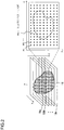
- Fig. 2 schematically illustrates the form of information acquired by the image processing apparatus 20 as a result of measurement performed by the sensor group 12.
- the sensors included in the sensor group 12 acquire the distribution of a predetermined physical quantity with respect to a plurality of plane surfaces 19a, 19b, ..., 19n perpendicular to a predetermined axis (z axis) as shown in the figure.
- the plane surfaces 19a, 19b, ..., 19n are located at different positions with respect to the z axis and are in the same range with respect to an xy plane surface that is perpendicular to the z axis.
- a direction for moving a plane surface for which the distribution of the physical quantity is acquired by the sensor group 12, just like the z axis in the figure, is referred to as "sensor axis," and the plane surface is referred to as “slice plane surface.”
- the sensor group 12 may be provided such that a plurality of sensor axes can be set.
- a group of a plurality of slice plane surfaces is set for each of the sensor axes, and the distribution of the physical quantity is obtained for each of the plane surfaces.
- a slice plane surface is perpendicular to the sensor axis.
- the slice plane surface does not always need to be perpendicular depending on a physical quantity to be measured, the structure of a sensor, or the like.
- the "distribution" can be obtained as a value for positional coordinates on each of such slice plane surfaces.
- the sensor group 12 is composed of n sensors 12_1, 12_2, ..., 12_N as shown in Fig. 1 , n values are obtained for a given position on a given slice plane surface.
- information acquired by the image processing apparatus 20 is information associating respective positional coordinates (x,y) with respective vector values (V_1, V_2, ..., V_N) composed of n values for each of a plurality of positions P1, P2, ..., set for each of the slice plane surfaces 19a, 19b, ..., 19n.
- the positions P1, P2, ... may be set at an interval of approximately a commonly-used pixel in practice. Depending on the resolution or the like of the sensors, it is appropriately designed that vector values of the same number of dimensions are obtained for each of the positions P1, P2, ... by interpolating or thinning out measurement values.
- the sensor group 12 may repeat measurement at a predetermined time interval, and the image processing apparatus 20 may acquire the information shown in Fig. 2 at each point of time. In this case, a three-dimensional object that is displayed at the end represents a moving image that changes over the passage of time.
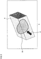
- Fig. 3 illustrates an example of an image generated by the image processing apparatus 20 and displayed on the display apparatus 14.
- An image example 4 represents the visualization of measurement information shown in Fig. 2 and is displayed in a state where the target object 16 exists inside a three-dimensional object 6 indicating the measurement space. The user can move a virtual viewpoint by operating the input apparatus 15 and rotate the three-dimensional object 6 at a desired angle, thus allowing the back side and lateral side of the target object to be checked.
- the desired area can be changed to transparent or translucent.
- the desired area can be changed to transparent or translucent.
- the three-dimensional object 6 When the three-dimensional object 6 is displayed as a moving image, the movement of the target object, the generation of a new target object, and the like are also observable. Also, an object, such as an arrow-shaped cursor 8, that is different from the measurement result can be displayed in a manner such that the object is displayed being inside the three-dimensional object 6.
- Fig. 4 illustrates the configuration of the image processing apparatus 20 in detail.
- the elements shown in functional blocks that indicate a variety of processes are implemented in hardware by any CPU (Central Processing Unit), GPU (Graphics Processing Unit), memory, or other LSI's, and in software by a program for performing image processes, etc.
- CPU Central Processing Unit
- GPU Graphics Processing Unit
- memory or other LSI's
- the image processing apparatus 20 controls transmission and reception of data to and from another apparatus in the image processing system 10. Since a commonly-practiced technique can be applied to such a process, the illustration thereof is omitted in the figure.
- the image processing apparatus 20 includes an image data generation unit 30 that acquires output information from the sensors and generates two-dimensional image data used for display, and a display processing unit 32 that draws a three-dimensional object using the two-dimensional image data.
- an image data generation unit 30 that acquires output information from the sensors and generates two-dimensional image data used for display
- a display processing unit 32 that draws a three-dimensional object using the two-dimensional image data.
- a process performed by the image data generation unit 30 and a process performed by the display processing unit 32 can be performed independently.
- both the image data generation unit 30 and the display processing unit 32 does not need to be provided in the same apparatus, and the image data generation unit 30 and the display processing unit 32 may be used as separate apparatuses that have respective functions.
- the image data generation unit 30 includes a sensor output data acquisition unit 42 that acquires output data from the sensor group 12, a slice image generation unit 44 that generates data of a two-dimensional image for each slice plane surface in which distribution is acquired, an image axis conversion unit 50 that generates the similar data of a two-dimensional image for a plurality of plane surfaces having a predetermined angle with respect to an axis that is different from a sensor axis, a vector value information storage unit 46 that stores data generated by the sensor output data acquisition unit 42, and a slice image storage unit 48 that stores data generated by the slice image generation unit 44 and the image axis conversion unit 50.
- the sensor output data acquisition unit 42 acquires distribution information of a physical quantity for each slice plane surface from the sensor group 12 and generates vector value information associating positional coordinates and a vector value as shown in Fig. 2 .
- the sensor output data acquisition unit 42 temporarily stores the vector value information in the vector value information storage unit 46 in association with identification information of the slice plane surface and notifies the slice image generation unit 44 and the image axis conversion unit 50 accordingly.
- the identification information of the slice surface is constituted of the direction of the sensor axis, the position on the sensor axis, and the like.
- the slice image generation unit 44 Based on the vector value information stored in the vector value information storage unit 46, the slice image generation unit 44 generates, for each slice plane surface, data of a two-dimensional image used to generate a three-dimensional object.
- a two-dimensional image is referred to as "slice image.”
- a slice image For each pixel, a slice image has an alpha value that indicates transmittance as well as information on a color space.
- the slice image generation unit 44 stores generated data of a slice image in the slice image storage unit 48 in association with the identification information of the slice plane surface.
- a drawing unit may calculate an alpha value and use the alpha value for blending, so that it becomes unnecessary to store the alpha value in a slice image storage unit.
- the image axis conversion unit 50 generates a plurality of plane surfaces that have a predetermined angle to the predetermined axis other than the sensor axis, like an x axis and y axis that are orthogonal to the z axis when the z axis is the sensor axis as shown in Fig. 2 , and generates vector value information similar to the one shown in Fig. 2 for each of the plane surfaces.
- the image axis conversion unit 50 reconstructs data as distribution for the plane surfaces.
- the image axis conversion unit 50 generates data of a two-dimensional image that corresponds to each of the plane surfaces.
- this two-dimensional image is also referred to as "slice image.”
- the axis used with respect to the plane surfaces in this case is referred to as "image axis" in order to differentiate the axis from "sensor axis.”
- the data of a slice image generated by the image axis conversion unit 50 is also stored in the slice image storage unit 48 in association with the direction of the image axis and the position on the axis.
- the display processing unit 32 includes a slice image management unit 52 that manages a slice image used for drawing in accordance with the position of a viewpoint or the like, a memory 56 for drawing that sequentially stores data of image that is necessary for drawing, an additional object image storage unit 58 that stores image data of an object that is additionally displayed such as a cursor, and an image drawing unit 54 that draws a three-dimensional object using the data of a slice image.
- a slice image management unit 52 that manages a slice image used for drawing in accordance with the position of a viewpoint or the like
- a memory 56 for drawing that sequentially stores data of image that is necessary for drawing
- an additional object image storage unit 58 that stores image data of an object that is additionally displayed such as a cursor
- an image drawing unit 54 that draws a three-dimensional object using the data of a slice image.
- the slice image management unit 52 switches an axis of a slice image to be used for drawing by moving a viewpoint and reads data of a necessary slice image from the slice image storage unit 48 into the memory 56 for drawing.
- the slice image storage unit 48 may also serve as the memory 56 for drawing.
- the slice image management unit 52 performs a drawing process while loading data gradually in the order necessary for drawing.
- slice images are basically superimposed by alpha blending process in order starting from the farthest from a viewpoint. Therefore, loading of slice image data into the memory 56 for drawing is also performed in the order basically. With this, latency to the time of display can be suppressed even when another slice image becomes necessary due to the movement of a viewpoint or the like.
- This loading process may be performed by a memory controller controlled by the slice image management unit 52.
- the slice image management unit 52 further performs interpolation of slice images in accordance with a decrease in a distance between the viewpoint and the three-dimensional object.
- the slice images are generated for discrete positions on the sensor axis or the image axis, and the discontinuity thereof becomes visually recognizable as the viewpoint becomes closer to the object.
- the slice image management unit 52 generates a new slice image having a pixel value that interpolates pixel values of adjacent slice images with respect to a position on the axis.
- the slice image management unit 52 inserts the generated slice image between the original slice images so as to make the discontinuity less noticeable by reducing an interval between the slice images.
- the number of slice images to be inserted may be gradually increased in a manner inversely proportional to a distance to the viewpoint or may be increased in stages according to a comparison of the distance with a threshold value.
- the image drawing unit 54 upon acquiring a notification from the slice image management unit 52 indicating that the data of a necessary slice image has been loaded into the memory 56 for drawing, draws a three-dimensional object using this data. Basically, the image drawing unit 54 arranges the slice images at respective positions on the axis and performs superimposition by projecting the slice images onto screen coordinates in order starting from the farthest from a viewpoint. Regarding the three-dimensional object of a measurement space displayed in this way, for example, a space outside of a target object becomes transparent or translucent by the setting of an alpha value. The image drawing unit 54 further draws an additional object such as a cursor in such the space.
- the image drawing unit 54 calculates a display position of the additional object in accordance with modes thereof and then reads out the data of the image into the memory 56 for drawing and draws the image. Further, the image drawing unit 54 may realize a stereoscopic view by performing a similar three-dimensional object drawing process for a plurality of viewpoints. The relative positions of the viewpoints or the like in this case can be appropriately determined according to a stereoscopic viewing method that is introduced.
- Fig. 5 is a flowchart illustrating a processing procedure for the image data generation unit 30 to generate the data of a slice image.
- the sensor output data acquisition unit 42 first acquires, in accordance with an instruction from the user or the like, distribution of N physical quantities for a plurality of slice plane surfaces of the sensor axis from the sensor group 12 and generates vector value information associating positions on the respective plane surfaces and vector values composed of a set of the physical quantities (S10).
- the vector values included in the vector value information may not be the N physical quantities themselves that are transmitted from the sensor group 12.
- physical quantities that do not need to be taken into account in the information desired to be displayed at the end may be excluded from the elements.
- values obtained as a result of carrying out an operation by different physical quantities may be added as new elements.
- masking by determination by a threshold value may be performed; for example, when a given physical quantity exceeds a threshold value, another physical value may be changed to zero.
- this method is effective when, for example, displaying only a target object of a certain temperature or less.
- a plurality of patterns may be generated for vector value information that can be obtained by manipulating measurement values as described above, and a target to be displayed may be switched by operation during the display.
- a specific processing rule of a physical quantity is, for example, determined by the user and stored as additional data in memory or the like that is not shown, and the sensor output data acquisition unit 42 refers to the processing rule at the time of generating vector value information.
- the slice image generation unit 44 determines an alpha value based on the vector values for each pixel in a two-dimensional array that is set for each of the slice plane surfaces (S12). A description will be made later regarding a specific method of determining an alpha value.
- the slice image generation unit 44 further generates data of a slice image that stores the color information and the alpha value as a pixel value and stores the data in the slice image storage unit 48 (S14).
- the color system of the color information such as RGB, YCbCr, or the like is not limited.
- the alpha value when generating an alpha value from a slice image at the time of drawing in the image drawing unit 54, the alpha value does not need to be set in the slice image generation unit 44. Thus, the alpha value is not stored in the image storage unit 48.
- the color information is determined in accordance with a rule that is set in advance according to the type of the physical quantity, a purpose of display, and the like.
- RGB may be expressed using respective values measured by the three sensors 12_1, 12_2, and 12_3 as red color luminance, green color luminance, and blue color luminance, respectively.
- a red color, a green color, and a blue color strongly show up respectively in a material in which a physical quantity measured by the sensor 12_1 is large, in a material in which a physical quantity measured by the sensor 12_2 is large, and in a material in which a physical quantity measured by the sensor 12_3 is large, allowing for color classification according to the materials.
- a single value that is measured by a certain sensor 12_1 may be substituted for all the R, G, and B, and the size of a physical quantity may be expressed by white color luminance.
- Rules for determining an alpha value and color information are appropriately determined by the user according to display contents, a purpose for display, and the like and are stored in memory or the like (not shown) in advance. Alternatively, the user may extemporarily set the rules via the input apparatus 15 while checking the actual display.
- the slice image generation unit 44 repeats respective processes in S12 and S14 (N in S16, S12, and S14).
- the image axis conversion unit 50 prepares a plurality of slice plane surfaces for a predetermined image axis at respective positions where physical quantities have been obtained and generates, for each image axis, vector value information associating positions on the respective plane surfaces and vector values composed of a set of the physical quantities (Y in S16, N in S18, S20, and S10).
- the image axis conversion unit 50 then repeats a process of generating a slice image after determining an alpha value and color information for a pixel that is set on each of the plane surfaces and storing the slice image until all slice images for each of the axes are generated (S12, S14, and N in S16).
- the image axis conversion unit 50 repeats respective processes in S10 and S20 in an environment where a physical quantity can be acquired by another sensor axis (N in S22). Once slice images have been generated for all the sensor axes, the process is ended (Y in S22).
- slice images for three axes are desirably prepared. The simplest way possible is to generate slice images for an x axis, a y axis, and a z axis that are orthogonal to one another. Any one of these axes in three directions may be used as an image axis. Alternatively, an image axis may not be included.
- the image axis conversion unit 50 does not need to perform the process.
- a sensor axis is in only one direction, slice images for other image axes are generated by the image axis conversion unit 50, and branching in S22 no longer exists.
- sensor axes are in two directions, the remaining single direction is used as an image axis, and the image axis conversion unit 50 generates slice images.
- the setting of an image axis may be appropriately changed according to directions that can be set as sensor axes and the number thereof.
- Fig. 6 illustrates an example of a method of determining an alpha value of a slice image in S12 in Fig. 5 .
- the upper side of the figure schematically shows vector value information in a slice plane surface 19i, and the lower side schematically shows an alpha value that is set in a corresponding slice image 100a.
- the slice plane surface 19i for example, in an area 102 where a target object exists and in the other area 104, at least either one of respective vector values changes greatly.
- the difference thereof is indicated by two types of shadings.
- Th represents a threshold value that is set in advance
- A represents an alpha value that is provided to each pixel.
- the alpha value is set to be 0. If the maximum value is the threshold value Th or larger, the alpha value is set to be 1.
- the alpha value is shown to be 1 by a white color in the area 102, and the alpha value is shown to be 0 by a black color in the area 104.
- the positions at which the vector values are stored on the respective slice plane surfaces in the vector value information and positions that define respective pixels on the slice images may be different. In that case, the alpha value is determined at the former positions, and a value for each of the pixels is determined by appropriately interpolating an alpha value.
- Conditional branching may be implemented after selecting a physical quantity used for branch determination.
- an alpha value is provided by such conditional branching when including a physical quantity whose value becomes high in the range of a target object in the vector values, an area outside the target object becomes transparent, and an area including the target object becomes translucent.
- ⁇ blending drawing is performed, display is shown where the far side can be seen through only behind the area outside the target object.
- Fig. 7 illustrates another example of a method of determining an alpha value of a slice image.
- the figure is expressed in the same way as in Fig. 6 .
- Conditional branching in this case is set as follows:
- the alpha value is set to be 0.
- the maximum value is the threshold value Th or larger, the maximum value itself is used as the alpha value.
- the physical quantities that constitute the vector values are previously normalized.
- gradation shows a change in a range of Th ⁇ A ⁇ 1 of the alpha value in the area 102.
- a change in a physical quantity inside a target object can be expressed by the transmittance of a color.
- the alpha value near the contour of the target object can be gradually changed.
- the alpha value can be changed according to the size of the physical quantities that constitute the vector values in the area outside a target object or the like.
- the ambient temperature, the ambient humidity, and the like of the target object can be expressed by the transmittance of a color.
- conditional branching are the same as those shown in Fig. 6 and Fig. 7 , except that the single physical quantity V_i is used for branching determination.
- the single physical quantity V_i is used for branching determination.
- a material that is displayed as the target object can be switched by switching the physical quantity V_i that is used.
- Th1 and Th2 may be provided, and the following conditional branching may be set.
- Fig. 8 is a diagram for explaining a method of suppressing the generation of such noise in the setting of the alpha value.
- An upper left graph shows the maximum value of the vector values in the horizontal axis and an alpha value A determined by the conditional branching shown in reference to Fig. 7 in the vertical axis.
- a final alpha value A is determined by converting the alpha value determined by the conditional branching by a predetermined rule. Therefore, the alpha value shown in the graph is set to be a provisional value as shown in the figure.
- the provisional value of the alpha value A is 0.
- the provisional value of the alpha value A becomes the maximum value Th.
- the final alpha value A is calculated by operating a function f(A) such as the one shown in the upper right of the figure.
- the function f(A) is, for example, a function that gradually rises from 0 in a provisional value of the alpha value that is smaller than the threshold value Th by the amount of a predetermined width ⁇ A and further reaches 1 while the provisional value becomes larger than the threshold value Th by the amount of the predetermined width ⁇ A. Multiplication of a value obtained by such a function to the provisional value of the alpha value A results in a graph such as the one shown in the bottom of the figure.
- the alpha value A when the maximum value of the vector values shown in the horizontal axis is smaller than the threshold value Th, the alpha value A is 0 as in the case of the provisional value.
- the alpha value A is suppressed to be smaller than the provisional value as a result of the multiplication of f(Th) to the provisional value Th.
- the function f(A) is optimized in advance according to the rate of occurrence of noise in the actual display image or the like.
- a value that is output after substituting the provisional value of the alpha value A for the function f may be set to be the alpha value A.
- the method of setting an alpha value shown thus far is a relatively simple method that is based on conditional branching. If it is desired to set an alpha value using a more complicated scheme, the alpha value may be prepared in advance for positional coordinates in an N-dimensional space formed by N physical quantities that constitute vector values. For example, when an alpha value is set using a different threshold value for each of physical quantities that constitute the vector values, it is possible that conditional branching becomes complicated.
- a table is prepared in advance that associates alpha values for all conditions with positional coordinates in an N-dimensional space, i.e., combinations of N values. This allows an alpha value to be directly retrieved from a vector value only by referring to the table without going through a process of conditional branching or the like.
- alpha values are calculated in advance for all the combinations of N values of the vector values and prepared as a table in the same way. This allows for a reduction in a processing load and in the amount of time required until the determination even when an alpha value is obtained using a complicated scheme.
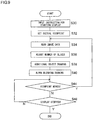
- Fig. 9 is a flowchart illustrating a processing procedure for the display processing unit 32 to perform a display process of a three-dimensional object.
- the slice image management unit 52 sets, as an initial viewpoint, viewpoint coordinates that are set in advance for displaying an initial image of the three-dimensional object and loads data of a slice image necessary for drawing the three-dimensional object from the viewpoint into the memory 56 for drawing (S32, S34).
- a subsequent object drawing process can be performed in parallel by loading slice images in order of necessity as described above.
- the slice image management unit 52 adjusts the number of the slice images in accordance with a distance between the viewpoint and the three-dimensional object (S36).
- the slice image management unit 52 stores the slice image in the memory 56 for drawing.
- image data itself is inserted between respective pieces of data of preceding and following slice images or is associated with a position on the axis at this time.
- the image drawing unit 54 draws an additional object to be displayed inside the three-dimensional object in accordance with, e.g., instruction input provided from the user via the input apparatus 15 (S38).
- the additional object is a cursor moved by the operation by the user, a marker displayed in contact with the target object, a line showing a trajectory of the target object, or the like and is set to be selectable by the user.
- the image drawing unit 54 determines a position at which the additional object is displayed based on designation by the user, a contour line of the target object obtained by an edge extraction process, or the like and then draws the additional object using the image data loaded into the memory 56 for drawing.
- the image drawing unit 54 draws a three-dimensional object that shows a measurement space by superimposing slice images loaded into the memory 56 for drawing, by alpha blending in order starting from the farthest from the viewpoint (S40).
- the process of drawing the additional object in S38 may be performed at the same time as the alpha blending drawing in S40.
- Fig. 10 schematically illustrates the way the image drawing unit 54 performs alpha blending drawing in S40 in Fig. 9 .
- a screen 116 slice images 110a, 110b, ..., 110n that correspond to the object, and a background 118 are located.
- An image projected to a given point 115 on the screen 116 is superimposition of respective images of intersection points 112a, 112b, ..., 112n, and 117 in order starting from the farthest from the viewpoint 114.
- intersection points 112a, 112b, ..., 112n, and 117 are points at the intersection of the line of sight 119 that passes the viewpoint 114 and a point 115 with the slice images 110a, 110b, ..., 110n, and the background 118, respectively.
- the superimposition is performed in the order of the intersection points 117, 112n, ..., 112b, and 112a.
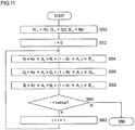
- Fig. 11 is a flowchart illustrating a processing procedure for obtaining RGB values at the point 115 on the screen shown in Fig. 10 .
- variables Ri, Gi, and Bi i is an integer of -1 or more
- RGB values, which are Rb, Gb, and Bb, at the intersection point 117 of the background 118 are substituted into R -1 , G -1 , and B -1 (S50).
- RGB values and an alpha value at the intersection point 112n on the slice image 110n which is the farthest slice image from the viewpoint, are denoted as (R 0 , G 0 , B 0 , A 0 ), respectively
- RGB values obtained when the intersection point 117 of the background 118 and the intersection point 112n on the slice image 110n are superimposed on each other are as follows (S52, S54, S56, and S58).
- R Kr * A 0 * R 0 + 1 ⁇ Kr * A 0 * R ⁇ 1
- G Kg * A 0 * G 0 + 1 ⁇ Kg * A 0 ⁇ G ⁇ 1
- B Kb * A 0 * B 0 + 1 ⁇ Kb * A 0 * B ⁇ 1
- Kr, Kg, and Kb are coefficients of the alpha value concerning red, green, and blue, respectively, when the alpha value held by a slice image is adjusted according to colors and are set in a range of 0 ⁇ K ⁇ 1 as necessary.
- RGB values where all the respective intersection points of nslice pieces of slice images are superimposed can be obtained while allowing for a state of transparent and translucent (N in S60).
- RGB values Kr * A k * R k + 1 ⁇ Kr * A k * R ′ k ⁇ 1
- G ′ k Kg * A k *G k + 1 ⁇ Kg * A k * G ′ k ⁇ 1
- B ′ k Kb * A k * G k + 1 ⁇ Kb * A k * B ′ k ⁇ 1
- the RGB values after the superimposition are denoted as (R' k , G' k , B' k ) in order to differentiate from RGB values of (R k , G k , B k ) for only the (k+1)th slice image.
- (Br i , Bg i , Bb i ) are coefficients of RGB values (R i , G i , B i ) of an (i+1)th slice image, respectively, and are calculated from the alpha value of the slice image. Therefore, in a mode where alpha values of all slice images are determined before the drawing, the final RGB values may be calculated using Expression 3 after first obtaining the coefficients (Br i , Bg i , Bb i ) in accordance with the viewpoint.
- Fig. 12 is a diagram for explaining a process for the slice image management unit 52 to determine data of a necessary slice image in accordance with the viewpoint in S34 in Fig. 9 .
- slice images are resultant of the imaging of distribution of physical quantities at discrete positions with respect to a predetermined axis.
- the sensor axis is a z axis in a vertical direction of the figure
- slice images that are generated are basically a plurality of parallel surfaces that constitute xy plane surfaces just like the slice image group 120.
- an image with no sense of incongruity can be drawn by performing superimposition such as the one explained in Fig. 10 .
- slice image groups are generated for a plurality of axes by generating slice images for an image axis different from the sensor axis in advance, or by measuring physical quantities for a plurality of sensor axes in advance, and a slice image group that is used is switched by the movement of the viewpoint.
- a slice image group 122 using the x axis as the image axis and a slice image group 124 using the y axis as the image axis are prepared.
- boundary lines are set starting from respective vertices of the three-dimensional object 126.
- the boundary lines make a predetermined angle to three sides of the three-dimensional object 126, which form the respective vertices.
- a trapezoidal space having these boundary lines as lateral face sides thereof and a surface of the three-dimensional object as an upper surface thereof is defined to be a single division.
- the slice image group 120 using the z axis as an axis thereof is used for drawing.
- the slice image group 122 using the x axis as an axis thereof is used for drawing.
- the slice image group 124 using the y axis as an axis thereof is used for drawing.
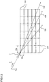
- Fig. 13 is a diagram for explaining an example of a method for determining an angle of a boundary line.
- slice image groups that use two directions orthogonal to each other as axes thereof are taken into consideration.
- both a slice image group that uses the x axis as an axis thereof and a slice image group that uses the y axis as an axis thereof are taking into consideration.
- the slice image group 122 (dashed line) that uses the x axis as the axis thereof and the slice image group 124 (solid line) that uses the y axis as the axis thereof are arranged on the same xy plane surface and viewed from the z axis direction.
- the line of sight that passes through a vertex v changes as shown by an arrow 128, 129, or 130 depending on the position of the viewpoint.
- the number of slice image groups that have points at the intersection with each line of sight is as follows in order of: (the slice image group 122 that uses the x axis as the axis thereof)/(the slice image group 124 that uses the y axis as the axis thereof).
- a sensor axis or an image axis is perpendicular to slice images.
- the present embodiment is not limited thereto.
- a slice image generated by the image axis conversion unit 50 by reconstructing the measurement value does not need to be perpendicular to the image axis, either.
- a boundary line can be also set based on the same theory as the one described above, and the same applies to a process of switching slice images according to the viewpoint and performing alpha blending drawing.
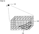
- Fig. 14 is a diagram for explaining another method for drawing a three-dimensional object.
- slice image groups for an x axis, a y axis, and a z axis are used at the same time as texture images in three directions.
- a commonly-practiced computer graphics drawing process can be applied to a method for drawing a three-dimensional object 136, in which a texture is attached to each surface thereof, according to the position of a viewpoint 132.
- slice images in each direction has an alpha channel, and superimposition starting from a pixel away from the viewpoint 132 is thus necessary as described above.
- the three-dimensional object 136 is divided in a lattice shape according to the slice image groups in the three directions.
- straight lines that intersect one another and that are shown in the three-dimensional object 136 represent respective edges of the slice images.
- An arrow 138 in the figure schematically shows such order.
- the three-dimensional object 136 can be expressed while allowing for both transparent and translucent states.
- the slice image management unit 52 loads data of the slice image groups in the three directions regardless of the position of the viewpoint.
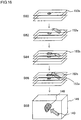
- Fig. 15 schematically illustrates, as one of the methods, a processing procedure for drawing the three-dimensional object after drawing the additional object first.
- the image drawing unit 54 prepares a virtual cuboid 142, where the three-dimensional object will be drawn at the end, according to the position of the viewpoint, and draws an additional object 140 at a necessary position inside the cuboid 142 by a commonly-practiced method (S70).
- the additional object 140 is a cursor figure of an arrow shape.
- the image drawing unit 54 then draws the three-dimensional object using slice images by the method described above (S72). Drawing the additional object 140 first allows for a state where the additional object 140 remains in an area of high transmittance where the alpha value is close to zero.
- a state where a cursor is floating inside the three-dimensional object 146 as the additional object 140 can be drawn (S74). For example, by positioning the cursor such that the cursor points to a target object 148 that exists inside the three-dimensional object 146, presentation or the like using display can be preferably realized.
- the trajectory of the target object may be displayed.
- another target object product
- the calculation of the position of the product may be performed separately, and the user may input the position as an input value.
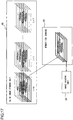
- Fig. 16 schematically illustrates a processing procedure according to another method for drawing the additional object.
- This examples shows a method of proceeding with the drawing of the three-dimensional object using slice images and drawing of the additional object in parallel with each other.
- the image drawing unit 54 performs alpha blending using the slice images up to a position where the additional object is drawn (S80).
- the image drawing unit 54 draws a portion 152a of the additional object that should be present in a space between a slice image 150a, which is located at the uppermost position at this time, and a subsequent slice image (S82).
- the image drawing unit 54 superimposes a slice image 150b positioned subsequently to the slice image 150a (S84).
- the image drawing unit 54 then draws a portion 152b of the additional object that should be present in a space between the slice image 150b and a subsequent slice image (S86).
- the entire additional object has been drawn at this stage.
- a state where a cursor is floating inside the three-dimensional object 146 as the additional object 140 can be drawn (S88).
- Fig. 17 schematically illustrates a procedure for reading slice image data when a result of measurement performed at a predetermined rate is displayed as a moving image of the three-dimensional object.
- slice image groups in three directions are generated for each point of time. However, the illustration of such slice image groups are omitted in the figure.
- the slice image management unit 52 performs loading into the memory 56 for drawing in order of slice images that are necessary for drawing.
- the slice image management unit 52 specifies a slice image that is farthest from the position of the viewpoint and starts loading data starting from the data of the slice image.
- a load unit composed of a plurality of slice images may be formed, and the loading may be performed based on the load unit.
- the respective pieces of data of three slice images shown by thick frames are simultaneously loaded as a load unit.
- the image drawing unit 54 starts reading slice image data in order from the memory 56 for drawing and performs alpha blending drawing.
- the slice image management unit 52 keeps loading respective pieces of data of subsequent slice images by a load unit by load unit basis.
- slice images are superimposed in order so as to draw a three-dimensional object.
- a measurement space is expressed by a three-dimensional object by generating slice images that have alpha channels from layered image information, which is cross section information of a target object acquired in a plurality of parallel plane surfaces, and performing alpha blending drawing. This allows for visualization of the target object and surrounding states thereof in an intuitively understandable manner using a commonly-practiced image processing function without increasing processing loads or necessary resources.
- Rules for determining an alpha value and color information can be variously changed at the stage of generating the slice images.
- the user generating an image can easily perform processing that is suitable for display contents and a purpose for display.
- slice images for a plurality of axes are generated in advance, and slice images used are switched at the time of displaying the three-dimensional object, according to the position of a viewpoint. Further, the number of the slice images is adjusted according to closeness to the viewpoint.
- a transparent space and a translucent space can be generated inside a three-dimensional object.
- an additional object such as a cursor can be displayed inside the three-dimensional object.
- the order of slice images used according to the position of a viewpoint can be determined.
- a loading process and a drawing process can be performed in parallel when data is loaded into memory from a secondary storage apparatus in the order.
- latency to the time of display can be suppressed even in a situation where the frequency of loading of data of slice images is high such as a case where a viewpoint is moved or where a three-dimensional object is shown as a moving image.
- smooth changing of display can be realized without increasing the capacity of memory.
- a slice plane surface is a plane surface that has a predetermined angle with respect to a sensor axis or an image axis.
- the slice plane surface may be a curved surface such as a spherical surface, a curved surface with fluctuation, or the like.
- Fig. 18 schematically illustrates the shape of a slice image when distribution with respect to a partially cylindrical curved surface or a partially spherical surface is measured.
- a sensor group 208 measures a measurement space in which a target object 216 exists.
- the distribution of measurement values at this time is obtained, using a z axis in a vertical direction of the figure as a sensor axis, with respect to a plurality of curved surfaces 210a, 210b, ..., 210n that are parallel to one another having the z axis as a center thereof.
- these curved surfaces are shown by fan-shaped curved lines at respective cross-sectional surfaces that pass through the sensor axis.
- the slice image generation unit 44 With respect to these slice curved surfaces 210a, 210b, ..., 210n, the slice image generation unit 44 generates slice images as described in the embodiment.
- the slice images generated at this time have the shape of a curved surface that is the same as that of the slice curved surfaces.
- the same process can be performed regardless of whether the shape of the slice images is a plane surface or a curved surface.
- the image axis conversion unit 50 prepares a plurality of plane surfaces or curved surfaces that cross the slice curved surfaces 210a, 210b, ..., 210n at a predetermined angle and extracts measurement values on the surfaces so as to generate slice image group in a direction different from the slice curved surfaces 210a, 210b, ..., 210n.
- slice image group is generated for plane surfaces 212a, 212b, ..., 212n that vertically cross the slice curved surfaces 210a, 210b, ..., 210 and that are perpendicular to the figure. Further, slice image group arranged in the depth direction of the figure is also generated.
- drawing is performed for each of small solids that are divided by the slice image groups of respective directions in the order that is the same as the one shown in Fig. 14 .
- the present invention is applicable to an information processing device such as computers, image processing apparatuses, and measuring apparatuses.
Landscapes
- Engineering & Computer Science (AREA)
- Physics & Mathematics (AREA)
- Health & Medical Sciences (AREA)
- Life Sciences & Earth Sciences (AREA)
- General Physics & Mathematics (AREA)
- Theoretical Computer Science (AREA)
- Computer Graphics (AREA)
- Public Health (AREA)
- Veterinary Medicine (AREA)
- Molecular Biology (AREA)
- Surgery (AREA)
- Animal Behavior & Ethology (AREA)
- General Health & Medical Sciences (AREA)
- Pathology (AREA)
- Medical Informatics (AREA)
- Biophysics (AREA)
- Heart & Thoracic Surgery (AREA)
- Biomedical Technology (AREA)
- Geometry (AREA)
- Image Processing (AREA)
- Processing Or Creating Images (AREA)
- Image Generation (AREA)
- Measuring And Recording Apparatus For Diagnosis (AREA)
Applications Claiming Priority (2)
| Application Number | Priority Date | Filing Date | Title |
|---|---|---|---|
| JP2011246279A JP5866177B2 (ja) | 2011-11-10 | 2011-11-10 | 画像処理装置および画像処理方法 |
| PCT/JP2012/006767 WO2013069215A1 (ja) | 2011-11-10 | 2012-10-23 | 画像処理装置、画像処理方法、および画像ファイルのデータ構造 |
Publications (3)
| Publication Number | Publication Date |
|---|---|
| EP2779109A1 EP2779109A1 (en) | 2014-09-17 |
| EP2779109A4 EP2779109A4 (en) | 2016-06-01 |
| EP2779109B1 true EP2779109B1 (en) | 2020-04-22 |
Family
ID=48289080
Family Applications (1)
| Application Number | Title | Priority Date | Filing Date |
|---|---|---|---|
| EP12847428.5A Active EP2779109B1 (en) | 2011-11-10 | 2012-10-23 | Image processing device, image processing method and image file data structure |
Country Status (5)
| Country | Link |
|---|---|
| US (1) | US9466146B2 (ja) |
| EP (1) | EP2779109B1 (ja) |
| JP (1) | JP5866177B2 (ja) |
| CN (1) | CN103918013B (ja) |
| WO (1) | WO2013069215A1 (ja) |
Families Citing this family (15)
| Publication number | Priority date | Publication date | Assignee | Title |
|---|---|---|---|---|
| US9132352B1 (en) | 2010-06-24 | 2015-09-15 | Gregory S. Rabin | Interactive system and method for rendering an object |
| US9754169B2 (en) * | 2011-12-16 | 2017-09-05 | Nec Corporation | Information processing system, information processing method, information processing device and control method and control program thereof, and communication terminal and control method and control program thereof |
| JP5988088B2 (ja) * | 2012-06-08 | 2016-09-07 | 富士通株式会社 | 描画プログラム、描画方法、および、描画装置 |
| KR20150033162A (ko) * | 2013-09-23 | 2015-04-01 | 삼성전자주식회사 | 컴포지터, 이를 포함하는 시스템온칩 및 이의 구동 방법 |
| JP5665068B1 (ja) * | 2014-09-05 | 2015-02-04 | 株式会社Live2D | プログラム、情報処理装置、制御方法及び記録媒体 |
| DE112015006312T5 (de) * | 2015-04-15 | 2017-12-28 | Olympus Corporation | Mikroskopiesystem, Mikroskopieverfahren und Mikroskopieprogramm |
| JP6738631B2 (ja) * | 2016-03-29 | 2020-08-12 | ザイオソフト株式会社 | 医用画像処理装置、医用画像処理方法、及び医用画像処理プログラム |
| CN106127862B (zh) * | 2016-06-16 | 2019-02-26 | 财付通支付科技有限公司 | 图形的处理方法和装置 |
| CN106210693A (zh) * | 2016-06-29 | 2016-12-07 | 联想(北京)有限公司 | 一种图像显示的方法、电子设备及电子装置 |
| KR101947692B1 (ko) * | 2017-06-23 | 2019-04-29 | 주식회사 맥스로텍 | 3d 모델 슬라이싱 장치 및 방법 |
| US20200388032A1 (en) * | 2019-06-04 | 2020-12-10 | JelloX Biotech Inc. | Three dimensional histopathology imaging method and system thereof |
| CN110505465B (zh) | 2019-08-30 | 2022-08-23 | 京东方科技集团股份有限公司 | 数据传输方法、三维图像显示方法、装置及电子设备 |
| EP4042378A1 (en) * | 2020-01-24 | 2022-08-17 | St. Jude Medical, Cardiology Division, Inc. | System and method for generating three dimensional geometric models of anatomical regions |
| CN114489315B (zh) * | 2020-11-12 | 2023-12-19 | 幻景启动股份有限公司 | 图像处理系统以及图像处理装置 |
| KR102353500B1 (ko) * | 2020-11-25 | 2022-01-20 | 한국전자기술연구원 | 공차 오류 문제를 해결하기 위한 3d 프린팅 슬라이싱 방법 |
Family Cites Families (12)
| Publication number | Priority date | Publication date | Assignee | Title |
|---|---|---|---|---|
| JPH05266215A (ja) * | 1992-03-18 | 1993-10-15 | Toshiba Corp | 画像表示装置 |
| US6297799B1 (en) * | 1998-11-12 | 2001-10-02 | James Knittel | Three-dimensional cursor for a real-time volume rendering system |
| AU2001239926A1 (en) * | 2000-02-25 | 2001-09-03 | The Research Foundation Of State University Of New York | Apparatus and method for volume processing and rendering |
| JP3529759B2 (ja) * | 2001-01-26 | 2004-05-24 | 株式会社ソニー・コンピュータエンタテインメント | 画像処理プログラム、画像処理プログラムを記録したコンピュータ読み取り可能な記録媒体、プログラム実行装置、画像処理装置、及び画像処理方法 |
| US7043701B2 (en) * | 2002-01-07 | 2006-05-09 | Xerox Corporation | Opacity desktop with depth perception |
| JP3589654B2 (ja) * | 2002-03-12 | 2004-11-17 | 独立行政法人理化学研究所 | ボリュームレンダリング方法とそのプログラム |
| JP2004141514A (ja) * | 2002-10-28 | 2004-05-20 | Toshiba Corp | 画像処理装置及び超音波診断装置 |
| JP3960382B2 (ja) * | 2003-06-18 | 2007-08-15 | 独立行政法人産業技術総合研究所 | テンソルボリュームデータの実時間可視化方法及び装置 |
| US7154500B2 (en) | 2004-04-20 | 2006-12-26 | The Chinese University Of Hong Kong | Block-based fragment filtration with feasible multi-GPU acceleration for real-time volume rendering on conventional personal computer |
| US8330763B2 (en) * | 2007-11-28 | 2012-12-11 | Siemens Aktiengesellschaft | Apparatus and method for volume rendering on multiple graphics processing units (GPUs) |
| US8044971B2 (en) * | 2008-01-31 | 2011-10-25 | Arm Norway As | Methods of and apparatus for processing computer graphics |
| DE102009042327A1 (de) * | 2009-09-21 | 2011-04-07 | Siemens Aktiengesellschaft | Effiziente Visualisierung von Objekteigenschaften mittels Volume Rendering |
-
2011
- 2011-11-10 JP JP2011246279A patent/JP5866177B2/ja active Active
-
2012
- 2012-10-23 WO PCT/JP2012/006767 patent/WO2013069215A1/ja active Application Filing
- 2012-10-23 EP EP12847428.5A patent/EP2779109B1/en active Active
- 2012-10-23 CN CN201280054856.6A patent/CN103918013B/zh active Active
- 2012-10-23 US US14/356,753 patent/US9466146B2/en active Active
Non-Patent Citations (4)
| Title |
|---|
| GARGESHA M ET AL: "Enhanced volume rendering techniques for high-resolution color cryo-imaging data", PROCEEDINGS OF THE SPIE - THE INTERNATIONAL SOCIETY FOR OPTICAL ENGINEERING SPIE - THE INTERNATIONAL SOCIETY FOR OPTICAL ENGINEERING USA, vol. 7262, 2009, pages 72622V (7 pp.), ISSN: 0277-786X * |
| JINMAN KIM ET AL: "Visualizing Dual-Modality Rendered Volumes Using a Dual-Lookup Table Transfer Function", COMPUTING IN SCIENCE AND ENGINEERING, IEEE SERVICE CENTER, LOS ALAMITOS, CA, US, vol. 9, no. 1, 1 January 2007 (2007-01-01), pages 20 - 25, XP011154601, ISSN: 1521-9615, DOI: 10.1109/MCSE.2007.22 * |
| LEVOY M: "Display of surfaces from volume data", IEEE COMPUTER GRAPHICS AND APPLICATIONS, IEEE SERVICE CENTER, NEW YORK, NY, US, vol. 8, no. 3, 1 May 1988 (1988-05-01), pages 29 - 37, XP011413670, ISSN: 0272-1716, DOI: 10.1109/38.511 * |
| LI JIANG ET AL: "<title>Dynamic characterization for tumor- and deformation-induced thermal contrasts on breast surface: a simulation study</title>", PROCEEDINGS OF SPIE, vol. 7262, 26 February 2009 (2009-02-26), pages 72621C - 72621C-7, XP055070978, ISSN: 0277-786X, DOI: 10.1117/12.812499 * |
Also Published As
| Publication number | Publication date |
|---|---|
| JP2013105188A (ja) | 2013-05-30 |
| EP2779109A1 (en) | 2014-09-17 |
| EP2779109A4 (en) | 2016-06-01 |
| JP5866177B2 (ja) | 2016-02-17 |
| US9466146B2 (en) | 2016-10-11 |
| US20140306952A1 (en) | 2014-10-16 |
| CN103918013A (zh) | 2014-07-09 |
| WO2013069215A1 (ja) | 2013-05-16 |
| CN103918013B (zh) | 2017-10-20 |
Similar Documents
| Publication | Publication Date | Title |
|---|---|---|
| EP2779109B1 (en) | Image processing device, image processing method and image file data structure | |
| EP3748584B1 (en) | Gradient adjustment for texture mapping for multiple render targets with resolution that varies by screen location | |
| US9959659B2 (en) | Tile-based rendering apparatus and method for rendering 3D graphics using binning information and property information | |
| JP5120926B2 (ja) | 画像処理装置、画像処理方法およびプログラム | |
| EP2831848B1 (en) | Method for estimating the opacity level in a scene and corresponding device | |
| US20130222383A1 (en) | Medical image display device and medical image display method | |
| EP2985735B1 (en) | Method and apparatus for performing tile-based path rendering | |
| EP3142074B1 (en) | Method and apparatus for performing path stroking | |
| CN106648049A (zh) | 一种基于眼球追踪及眼动点预测的立体渲染方法 | |
| JP4885042B2 (ja) | 画像処理方法および装置ならびにプログラム | |
| JP2018101415A (ja) | キューブマップをテクスチャリングするためのlodを決定する方法、装置、コンピュータプログラム及び記録媒体 | |
| JP4803581B2 (ja) | 景観解析方法とこの方法を実行するコンピュータプログラムおよびこのプログラムを格納した媒体 | |
| US9898838B2 (en) | Graphics processing apparatus and method for determining level of detail (LOD) for texturing in graphics pipeline | |
| US20170061682A1 (en) | Rendering method and apparatus | |
| US9892534B2 (en) | Method and apparatus for performing path rendering | |
| EP2876607B1 (en) | Shape data generation method and device | |
| KR101227155B1 (ko) | 저해상도 그래픽 영상을 고해상도 그래픽 영상으로 실시간 변환하는 그래픽 영상 처리 장치 및 방법 | |
| JP6106293B2 (ja) | 画像処理装置、画像処理システム、および画像処理方法 | |
| JP2008259698A (ja) | 画像処理方法および装置並びにプログラム | |
| US6856325B2 (en) | Information processing method and apparatus | |
| Konev et al. | Fast cutaway visualization of sub-terrain tubular networks | |
| US10453247B1 (en) | Vertex shift for rendering 360 stereoscopic content | |
| Eichelbaum et al. | Fabric-like visualization of tensor field data on arbitrary surfaces in image space | |
| CN107978015B (zh) | 一种自适应实时三维体绘制的加速方法和装置 | |
| US20170148209A1 (en) | Tri-Cubic and Hybrid Interpolation in a 3D Texture Shader |
Legal Events
| Date | Code | Title | Description |
|---|---|---|---|
| PUAI | Public reference made under article 153(3) epc to a published international application that has entered the european phase |
Free format text: ORIGINAL CODE: 0009012 |
|
| 17P | Request for examination filed |
Effective date: 20140520 |
|
| AK | Designated contracting states |
Kind code of ref document: A1 Designated state(s): AL AT BE BG CH CY CZ DE DK EE ES FI FR GB GR HR HU IE IS IT LI LT LU LV MC MK MT NL NO PL PT RO RS SE SI SK SM TR |
|
| DAX | Request for extension of the european patent (deleted) | ||
| RIC1 | Information provided on ipc code assigned before grant |
Ipc: G06T 7/00 20060101ALI20151126BHEP Ipc: G06T 15/08 20110101AFI20151126BHEP |
|
| RIC1 | Information provided on ipc code assigned before grant |
Ipc: A61B 5/05 20060101ALI20160407BHEP Ipc: G06T 15/08 20110101AFI20160407BHEP Ipc: A61B 5/00 20060101ALI20160407BHEP Ipc: A61B 5/103 20060101ALI20160407BHEP Ipc: G06T 7/00 20060101ALI20160407BHEP Ipc: A61B 5/01 20060101ALI20160407BHEP Ipc: G06T 15/10 20060101ALI20160407BHEP |
|
| RA4 | Supplementary search report drawn up and despatched (corrected) |
Effective date: 20160503 |
|
| RIC1 | Information provided on ipc code assigned before grant |
Ipc: G06T 15/10 20060101ALI20160425BHEP Ipc: G06T 15/08 20110101AFI20160425BHEP Ipc: A61B 5/01 20060101ALI20160425BHEP Ipc: A61B 5/05 20060101ALI20160425BHEP Ipc: A61B 5/00 20060101ALI20160425BHEP Ipc: G06T 7/00 20060101ALI20160425BHEP Ipc: A61B 5/103 20060101ALI20160425BHEP |
|
| RAP1 | Party data changed (applicant data changed or rights of an application transferred) |
Owner name: SONY INTERACTIVE ENTERTAINMENT INC. Owner name: SONY CORPORATION |
|
| STAA | Information on the status of an ep patent application or granted ep patent |
Free format text: STATUS: EXAMINATION IS IN PROGRESS |
|
| 17Q | First examination report despatched |
Effective date: 20170324 |
|
| GRAP | Despatch of communication of intention to grant a patent |
Free format text: ORIGINAL CODE: EPIDOSNIGR1 |
|
| STAA | Information on the status of an ep patent application or granted ep patent |
Free format text: STATUS: GRANT OF PATENT IS INTENDED |
|
| INTG | Intention to grant announced |
Effective date: 20191128 |
|
| GRAS | Grant fee paid |
Free format text: ORIGINAL CODE: EPIDOSNIGR3 |
|
| GRAA | (expected) grant |
Free format text: ORIGINAL CODE: 0009210 |
|
| STAA | Information on the status of an ep patent application or granted ep patent |
Free format text: STATUS: THE PATENT HAS BEEN GRANTED |
|
| AK | Designated contracting states |
Kind code of ref document: B1 Designated state(s): AL AT BE BG CH CY CZ DE DK EE ES FI FR GB GR HR HU IE IS IT LI LT LU LV MC MK MT NL NO PL PT RO RS SE SI SK SM TR |
|
| REG | Reference to a national code |
Ref country code: GB Ref legal event code: FG4D |
|
| REG | Reference to a national code |
Ref country code: CH Ref legal event code: EP |
|
| REG | Reference to a national code |
Ref country code: IE Ref legal event code: FG4D |
|
| REG | Reference to a national code |
Ref country code: DE Ref legal event code: R096 Ref document number: 602012069541 Country of ref document: DE |
|
| REG | Reference to a national code |
Ref country code: AT Ref legal event code: REF Ref document number: 1261129 Country of ref document: AT Kind code of ref document: T Effective date: 20200515 |
|
| REG | Reference to a national code |
Ref country code: LT Ref legal event code: MG4D |
|
| REG | Reference to a national code |
Ref country code: NL Ref legal event code: MP Effective date: 20200422 |
|
| PG25 | Lapsed in a contracting state [announced via postgrant information from national office to epo] |
Ref country code: SE Free format text: LAPSE BECAUSE OF FAILURE TO SUBMIT A TRANSLATION OF THE DESCRIPTION OR TO PAY THE FEE WITHIN THE PRESCRIBED TIME-LIMIT Effective date: 20200422 Ref country code: NL Free format text: LAPSE BECAUSE OF FAILURE TO SUBMIT A TRANSLATION OF THE DESCRIPTION OR TO PAY THE FEE WITHIN THE PRESCRIBED TIME-LIMIT Effective date: 20200422 Ref country code: NO Free format text: LAPSE BECAUSE OF FAILURE TO SUBMIT A TRANSLATION OF THE DESCRIPTION OR TO PAY THE FEE WITHIN THE PRESCRIBED TIME-LIMIT Effective date: 20200722 Ref country code: GR Free format text: LAPSE BECAUSE OF FAILURE TO SUBMIT A TRANSLATION OF THE DESCRIPTION OR TO PAY THE FEE WITHIN THE PRESCRIBED TIME-LIMIT Effective date: 20200723 Ref country code: FI Free format text: LAPSE BECAUSE OF FAILURE TO SUBMIT A TRANSLATION OF THE DESCRIPTION OR TO PAY THE FEE WITHIN THE PRESCRIBED TIME-LIMIT Effective date: 20200422 Ref country code: PT Free format text: LAPSE BECAUSE OF FAILURE TO SUBMIT A TRANSLATION OF THE DESCRIPTION OR TO PAY THE FEE WITHIN THE PRESCRIBED TIME-LIMIT Effective date: 20200824 Ref country code: IS Free format text: LAPSE BECAUSE OF FAILURE TO SUBMIT A TRANSLATION OF THE DESCRIPTION OR TO PAY THE FEE WITHIN THE PRESCRIBED TIME-LIMIT Effective date: 20200822 Ref country code: LT Free format text: LAPSE BECAUSE OF FAILURE TO SUBMIT A TRANSLATION OF THE DESCRIPTION OR TO PAY THE FEE WITHIN THE PRESCRIBED TIME-LIMIT Effective date: 20200422 |
|
| REG | Reference to a national code |
Ref country code: AT Ref legal event code: MK05 Ref document number: 1261129 Country of ref document: AT Kind code of ref document: T Effective date: 20200422 |
|
| PG25 | Lapsed in a contracting state [announced via postgrant information from national office to epo] |
Ref country code: RS Free format text: LAPSE BECAUSE OF FAILURE TO SUBMIT A TRANSLATION OF THE DESCRIPTION OR TO PAY THE FEE WITHIN THE PRESCRIBED TIME-LIMIT Effective date: 20200422 Ref country code: BG Free format text: LAPSE BECAUSE OF FAILURE TO SUBMIT A TRANSLATION OF THE DESCRIPTION OR TO PAY THE FEE WITHIN THE PRESCRIBED TIME-LIMIT Effective date: 20200722 Ref country code: LV Free format text: LAPSE BECAUSE OF FAILURE TO SUBMIT A TRANSLATION OF THE DESCRIPTION OR TO PAY THE FEE WITHIN THE PRESCRIBED TIME-LIMIT Effective date: 20200422 Ref country code: HR Free format text: LAPSE BECAUSE OF FAILURE TO SUBMIT A TRANSLATION OF THE DESCRIPTION OR TO PAY THE FEE WITHIN THE PRESCRIBED TIME-LIMIT Effective date: 20200422 |
|
| PG25 | Lapsed in a contracting state [announced via postgrant information from national office to epo] |
Ref country code: AL Free format text: LAPSE BECAUSE OF FAILURE TO SUBMIT A TRANSLATION OF THE DESCRIPTION OR TO PAY THE FEE WITHIN THE PRESCRIBED TIME-LIMIT Effective date: 20200422 |
|
| REG | Reference to a national code |
Ref country code: DE Ref legal event code: R097 Ref document number: 602012069541 Country of ref document: DE |
|
| PG25 | Lapsed in a contracting state [announced via postgrant information from national office to epo] |
Ref country code: RO Free format text: LAPSE BECAUSE OF FAILURE TO SUBMIT A TRANSLATION OF THE DESCRIPTION OR TO PAY THE FEE WITHIN THE PRESCRIBED TIME-LIMIT Effective date: 20200422 Ref country code: CZ Free format text: LAPSE BECAUSE OF FAILURE TO SUBMIT A TRANSLATION OF THE DESCRIPTION OR TO PAY THE FEE WITHIN THE PRESCRIBED TIME-LIMIT Effective date: 20200422 Ref country code: DK Free format text: LAPSE BECAUSE OF FAILURE TO SUBMIT A TRANSLATION OF THE DESCRIPTION OR TO PAY THE FEE WITHIN THE PRESCRIBED TIME-LIMIT Effective date: 20200422 Ref country code: IT Free format text: LAPSE BECAUSE OF FAILURE TO SUBMIT A TRANSLATION OF THE DESCRIPTION OR TO PAY THE FEE WITHIN THE PRESCRIBED TIME-LIMIT Effective date: 20200422 Ref country code: SM Free format text: LAPSE BECAUSE OF FAILURE TO SUBMIT A TRANSLATION OF THE DESCRIPTION OR TO PAY THE FEE WITHIN THE PRESCRIBED TIME-LIMIT Effective date: 20200422 Ref country code: AT Free format text: LAPSE BECAUSE OF FAILURE TO SUBMIT A TRANSLATION OF THE DESCRIPTION OR TO PAY THE FEE WITHIN THE PRESCRIBED TIME-LIMIT Effective date: 20200422 Ref country code: EE Free format text: LAPSE BECAUSE OF FAILURE TO SUBMIT A TRANSLATION OF THE DESCRIPTION OR TO PAY THE FEE WITHIN THE PRESCRIBED TIME-LIMIT Effective date: 20200422 Ref country code: ES Free format text: LAPSE BECAUSE OF FAILURE TO SUBMIT A TRANSLATION OF THE DESCRIPTION OR TO PAY THE FEE WITHIN THE PRESCRIBED TIME-LIMIT Effective date: 20200422 |
|
| PG25 | Lapsed in a contracting state [announced via postgrant information from national office to epo] |
Ref country code: PL Free format text: LAPSE BECAUSE OF FAILURE TO SUBMIT A TRANSLATION OF THE DESCRIPTION OR TO PAY THE FEE WITHIN THE PRESCRIBED TIME-LIMIT Effective date: 20200422 Ref country code: SK Free format text: LAPSE BECAUSE OF FAILURE TO SUBMIT A TRANSLATION OF THE DESCRIPTION OR TO PAY THE FEE WITHIN THE PRESCRIBED TIME-LIMIT Effective date: 20200422 |
|
| PLBE | No opposition filed within time limit |
Free format text: ORIGINAL CODE: 0009261 |
|
| STAA | Information on the status of an ep patent application or granted ep patent |
Free format text: STATUS: NO OPPOSITION FILED WITHIN TIME LIMIT |
|
| 26N | No opposition filed |
Effective date: 20210125 |
|
| PG25 | Lapsed in a contracting state [announced via postgrant information from national office to epo] |
Ref country code: SI Free format text: LAPSE BECAUSE OF FAILURE TO SUBMIT A TRANSLATION OF THE DESCRIPTION OR TO PAY THE FEE WITHIN THE PRESCRIBED TIME-LIMIT Effective date: 20200422 |
|
| REG | Reference to a national code |
Ref country code: CH Ref legal event code: PL |
|
| PG25 | Lapsed in a contracting state [announced via postgrant information from national office to epo] |
Ref country code: LU Free format text: LAPSE BECAUSE OF NON-PAYMENT OF DUE FEES Effective date: 20201023 Ref country code: MC Free format text: LAPSE BECAUSE OF FAILURE TO SUBMIT A TRANSLATION OF THE DESCRIPTION OR TO PAY THE FEE WITHIN THE PRESCRIBED TIME-LIMIT Effective date: 20200422 |
|
| REG | Reference to a national code |
Ref country code: BE Ref legal event code: MM Effective date: 20201031 |
|
| PG25 | Lapsed in a contracting state [announced via postgrant information from national office to epo] |
Ref country code: LI Free format text: LAPSE BECAUSE OF NON-PAYMENT OF DUE FEES Effective date: 20201031 Ref country code: BE Free format text: LAPSE BECAUSE OF NON-PAYMENT OF DUE FEES Effective date: 20201031 Ref country code: CH Free format text: LAPSE BECAUSE OF NON-PAYMENT OF DUE FEES Effective date: 20201031 |
|
| PG25 | Lapsed in a contracting state [announced via postgrant information from national office to epo] |
Ref country code: IE Free format text: LAPSE BECAUSE OF NON-PAYMENT OF DUE FEES Effective date: 20201023 |
|
| PG25 | Lapsed in a contracting state [announced via postgrant information from national office to epo] |
Ref country code: TR Free format text: LAPSE BECAUSE OF FAILURE TO SUBMIT A TRANSLATION OF THE DESCRIPTION OR TO PAY THE FEE WITHIN THE PRESCRIBED TIME-LIMIT Effective date: 20200422 Ref country code: MT Free format text: LAPSE BECAUSE OF FAILURE TO SUBMIT A TRANSLATION OF THE DESCRIPTION OR TO PAY THE FEE WITHIN THE PRESCRIBED TIME-LIMIT Effective date: 20200422 Ref country code: CY Free format text: LAPSE BECAUSE OF FAILURE TO SUBMIT A TRANSLATION OF THE DESCRIPTION OR TO PAY THE FEE WITHIN THE PRESCRIBED TIME-LIMIT Effective date: 20200422 |
|
| PG25 | Lapsed in a contracting state [announced via postgrant information from national office to epo] |
Ref country code: MK Free format text: LAPSE BECAUSE OF FAILURE TO SUBMIT A TRANSLATION OF THE DESCRIPTION OR TO PAY THE FEE WITHIN THE PRESCRIBED TIME-LIMIT Effective date: 20200422 |
|
| P01 | Opt-out of the competence of the unified patent court (upc) registered |
Effective date: 20230519 |
|
| P02 | Opt-out of the competence of the unified patent court (upc) changed |
Effective date: 20230527 |
|
| PGFP | Annual fee paid to national office [announced via postgrant information from national office to epo] |
Ref country code: GB Payment date: 20230920 Year of fee payment: 12 |
|
| PGFP | Annual fee paid to national office [announced via postgrant information from national office to epo] |
Ref country code: FR Payment date: 20230920 Year of fee payment: 12 |
|
| PGFP | Annual fee paid to national office [announced via postgrant information from national office to epo] |
Ref country code: DE Payment date: 20230920 Year of fee payment: 12 |