EP2778795A1 - Image forming apparatus and image forming method - Google Patents
Image forming apparatus and image forming method Download PDFInfo
- Publication number
- EP2778795A1 EP2778795A1 EP13198472.6A EP13198472A EP2778795A1 EP 2778795 A1 EP2778795 A1 EP 2778795A1 EP 13198472 A EP13198472 A EP 13198472A EP 2778795 A1 EP2778795 A1 EP 2778795A1
- Authority
- EP
- European Patent Office
- Prior art keywords
- fixing
- rotary body
- recording medium
- heat shield
- fixing rotary
- Prior art date
- Legal status (The legal status is an assumption and is not a legal conclusion. Google has not performed a legal analysis and makes no representation as to the accuracy of the status listed.)
- Granted
Links
Images







Classifications
-
- G—PHYSICS
- G03—PHOTOGRAPHY; CINEMATOGRAPHY; ANALOGOUS TECHNIQUES USING WAVES OTHER THAN OPTICAL WAVES; ELECTROGRAPHY; HOLOGRAPHY
- G03G—ELECTROGRAPHY; ELECTROPHOTOGRAPHY; MAGNETOGRAPHY
- G03G15/00—Apparatus for electrographic processes using a charge pattern
- G03G15/20—Apparatus for electrographic processes using a charge pattern for fixing, e.g. by using heat
- G03G15/2003—Apparatus for electrographic processes using a charge pattern for fixing, e.g. by using heat using heat
- G03G15/2014—Apparatus for electrographic processes using a charge pattern for fixing, e.g. by using heat using heat using contact heat
- G03G15/2039—Apparatus for electrographic processes using a charge pattern for fixing, e.g. by using heat using heat using contact heat with means for controlling the fixing temperature
-
- G—PHYSICS
- G03—PHOTOGRAPHY; CINEMATOGRAPHY; ANALOGOUS TECHNIQUES USING WAVES OTHER THAN OPTICAL WAVES; ELECTROGRAPHY; HOLOGRAPHY
- G03G—ELECTROGRAPHY; ELECTROPHOTOGRAPHY; MAGNETOGRAPHY
- G03G15/00—Apparatus for electrographic processes using a charge pattern
- G03G15/20—Apparatus for electrographic processes using a charge pattern for fixing, e.g. by using heat
- G03G15/2003—Apparatus for electrographic processes using a charge pattern for fixing, e.g. by using heat using heat
- G03G15/2014—Apparatus for electrographic processes using a charge pattern for fixing, e.g. by using heat using heat using contact heat
- G03G15/2053—Structural details of heat elements, e.g. structure of roller or belt, eddy current, induction heating
-
- G—PHYSICS
- G03—PHOTOGRAPHY; CINEMATOGRAPHY; ANALOGOUS TECHNIQUES USING WAVES OTHER THAN OPTICAL WAVES; ELECTROGRAPHY; HOLOGRAPHY
- G03G—ELECTROGRAPHY; ELECTROPHOTOGRAPHY; MAGNETOGRAPHY
- G03G15/00—Apparatus for electrographic processes using a charge pattern
- G03G15/20—Apparatus for electrographic processes using a charge pattern for fixing, e.g. by using heat
- G03G15/2003—Apparatus for electrographic processes using a charge pattern for fixing, e.g. by using heat using heat
- G03G15/2014—Apparatus for electrographic processes using a charge pattern for fixing, e.g. by using heat using heat using contact heat
- G03G15/2039—Apparatus for electrographic processes using a charge pattern for fixing, e.g. by using heat using heat using contact heat with means for controlling the fixing temperature
- G03G15/2042—Apparatus for electrographic processes using a charge pattern for fixing, e.g. by using heat using heat using contact heat with means for controlling the fixing temperature specially for the axial heat partition
-
- G—PHYSICS
- G03—PHOTOGRAPHY; CINEMATOGRAPHY; ANALOGOUS TECHNIQUES USING WAVES OTHER THAN OPTICAL WAVES; ELECTROGRAPHY; HOLOGRAPHY
- G03G—ELECTROGRAPHY; ELECTROPHOTOGRAPHY; MAGNETOGRAPHY
- G03G15/00—Apparatus for electrographic processes using a charge pattern
- G03G15/55—Self-diagnostics; Malfunction or lifetime display
-
- G—PHYSICS
- G03—PHOTOGRAPHY; CINEMATOGRAPHY; ANALOGOUS TECHNIQUES USING WAVES OTHER THAN OPTICAL WAVES; ELECTROGRAPHY; HOLOGRAPHY
- G03G—ELECTROGRAPHY; ELECTROPHOTOGRAPHY; MAGNETOGRAPHY
- G03G2215/00—Apparatus for electrophotographic processes
- G03G2215/20—Details of the fixing device or porcess
- G03G2215/2003—Structural features of the fixing device
- G03G2215/2016—Heating belt
- G03G2215/2035—Heating belt the fixing nip having a stationary belt support member opposing a pressure member
Definitions
- Exemplary aspects of the present invention relate to an image forming apparatus and an image forming method, and more particularly, to an image forming apparatus for forming a toner image on a recording medium and an image forming method performed by the image forming apparatus.
- Related-art image forming apparatuses such as copiers, facsimile machines, printers, or multifunction printers having two or more of copying, printing, scanning, facsimile, plotter, and other functions, typically form an image on a recording medium according to image data.
- a charger uniformly charges a surface of a photoconductor; an optical writer emits a light beam onto the charged surface of the photoconductor to form an electrostatic latent image on the photoconductor according to the image data; a development device supplies toner to the electrostatic latent image formed on the photoconductor to render the electrostatic latent image visible as a toner image; the toner image is directly transferred from the photoconductor onto a recording medium or is indirectly transferred from the photoconductor onto a recording medium via an intermediate transfer belt; finally, a fixing device applies heat and pressure to the recording medium bearing the toner image to fix the toner image on the recording medium, thus forming the image on the recording medium.
- Such fixing device may include a fixing rotary body heated by a heater and an opposed body contacting the fixing rotary body to form a fixing nip therebetween through which a recording medium bearing a toner image is conveyed.
- the fixing rotary body and the opposed body rotate and convey the recording medium bearing the toner image through the fixing nip
- the fixing rotary body heated to a predetermined fixing temperature and the opposed body together heat and melt toner of the toner image, thus fixing the toner image on the recording medium.
- a temperature sensor detects the temperature of the fixing rotary body to maintain the fixing rotary body at a desired temperature. Conversely, at each lateral end of the fixing rotary body in an axial direction thereof, the recording medium is not conveyed over the fixing rotary body and therefore does not draw heat from the fixing rotary body. Accordingly, after a plurality of recording media is conveyed through the fixing nip continuously, a non-conveyance span situated at each lateral end of the fixing rotary body may overheat.
- the fixing device may incorporate a heat shield to shield the non-conveyance span of the fixing rotary body from the heater, thus preventing overheating of the fixing rotary body as disclosed by JP-2008-058833-A and JP-2008-139779-A , for example.
- the heat shield is movable to shield the fixing rotary body from the heater in a variable span on the fixing rotary body according to the size of the recording medium. For example, the heat shield moves from a home position where the heat shield does not shield the fixing rotary body from the heater to a shield position where the heat shield shields the fixing rotary body from the heater.
- the image forming apparatus may stop urgently when a fault occurs, for example, when the recording medium is jammed between the fixing rotary body and the opposed body.
- the heat shield returns to the home position.
- the fixing device may stop with delay, resulting damage to the components including the fixing rotary body that are incorporated in the fixing device.
- the image forming apparatus includes a fixing device including a fixing rotary body rotatable in a predetermined direction of rotation and a heater disposed opposite and heating the fixing rotary body. An opposed body contacts the fixing rotary body with releasable pressure therebetween to form a fixing nip therebetween through which a recording medium is conveyed.
- a heat shield is interposed between the heater and the fixing rotary body and movable in a circumferential direction of the fixing rotary body to shield the fixing rotary body from the heater in a variable circumferential direct heating span of the fixing rotary body where the heater is disposed opposite the fixing rotary body directly.
- a controller is operatively connected to the heater and the heat shield to halt the heat shield instantly when a fault occurs during a print job.
- the controller halts the fixing device quickly, reducing damage to the components including the fixing rotary body which are incorporated in the fixing device.
- the controller moves the heat shield to a home position where the heat shield is disposed opposite the heater indirectly when the fault is eliminated.
- the image forming apparatus further includes a recording medium detector operatively connected to the controller and disposed downstream from the fixing nip in a recording medium conveyance direction to detect the recording medium.
- the fixing rotary body rotates forward in the predetermined direction of rotation after the controller turns off the heater as the recording medium detector detects the recording medium when the fault occurs.
- the fixing rotary body rotates forward in the predetermined direction of rotation at a linear velocity slower than a linear velocity at which the fixing rotary body rotates during the print job.
- the pressure between the opposed body and the fixing rotary body is released after the fixing rotary body halts after the fixing rotary body rotates forward in the predetermined direction of rotation.
- the image forming apparatus further includes an alarm operatively connected to the controller to issue an alarm after the pressure between the opposed body and the fixing rotary body is released.
- the fixing rotary body rotates backward in a direction counter to the predetermined direction of rotation after the controller turns off the heater as the recording medium detector does not detect the recording medium when the fault occurs.
- the fixing rotary body rotates backward in the direction counter to the predetermined direction of rotation at a linear velocity slower than a linear velocity at which the fixing rotary body rotates during the print job.
- the pressure between the opposed body and the fixing rotary body is released after the fixing rotary body halts after the fixing rotary body rotates backward in the direction counter to the predetermined direction of rotation.
- the image forming apparatus further includes a position detector operatively connected to the controller and linked with the heat shield to detect a position of the heat shield.
- the position detector includes a feeler connected to the heat shield and pivotable in the circumferential direction of the fixing rotary body in accordance with movement of the heat shield; a home position sensor defining a home position where the heat shield is disposed opposite the heater indirectly to detect the feeler as the feeler overlaps the home position sensor; and an angle sensor disposed downstream from the home position sensor in the direction of rotation of the fixing rotary body to detect the feeler as the feeler overlaps the angle sensor.
- the angle sensor defines a reference position of the heat shield.
- an image forming method includes rotating a fixing rotary body forward at an increased linear velocity to convey a recording medium through a fixing nip formed between the fixing rotary body and an opposed body contacted by the fixing rotary body with pressure therebetween; moving a heat shield to a shield position where the heat shield shields the fixing rotary body from a heater; detecting a fault; detecting the recording medium discharged from the fixing nip; turning off the heater; rotating the fixing rotary body forward at a decreased linear velocity for a preset time; halting the fixing rotary body; releasing the pressure between the fixing rotary body and the opposed body; and issuing an alarm about the fault.
- the image forming method further includes receiving a recovery signal indicating the fault is eliminated; moving the heat shield to a home position where the heat shield does not shield the fixing rotary body from the heater; pressing the opposed body against the fixing rotary body; rotating the fixing rotary body forward; and turning on the heater.
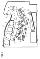
- FIG. 1 an image forming apparatus 1 according to an exemplary embodiment of the present invention is explained.
- FIG. 1 is a schematic vertical sectional view of the image forming apparatus 1.
- the image forming apparatus 1 may be a copier, a facsimile machine, a printer, a multifunction peripheral or a multifunction printer (MFP) having at least one of copying, printing, scanning, facsimile, and plotter functions, or the like.
- the image forming apparatus 1 is a color laser printer that forms color and monochrome toner images on recording media by electrophotography.
- the image forming apparatus 1 includes four image forming devices 4Y, 4M, 4C, and 4K situated in a center portion thereof.
- the image forming devices 4Y, 4M, 4C, and 4K contain yellow, magenta, cyan, and black developers (e.g., toners) that form yellow, magenta, cyan, and black toner images, respectively, resulting in a color toner image, they have an identical structure.
- each of the image forming devices 4Y, 4M, 4C, and 4K includes a drum-shaped photoconductor 5 serving as an image carrier that carries an electrostatic latent image and a resultant toner image; a charger 6 that charges an outer circumferential surface of the photoconductor 5; a development device 7 that supplies toner to the electrostatic latent image formed on the outer circumferential surface of the photoconductor 5, thus visualizing the electrostatic latent image as a toner image; and a cleaner 8 that cleans the outer circumferential surface of the photoconductor 5.
- a drum-shaped photoconductor 5 serving as an image carrier that carries an electrostatic latent image and a resultant toner image
- a charger 6 that charges an outer circumferential surface of the photoconductor 5
- a development device 7 that supplies toner to the electrostatic latent image formed on the outer circumferential surface of the photoconductor 5, thus visualizing the electrostatic latent image as a toner image
- a cleaner 8 that cleans the
- reference numerals are assigned to the photoconductor 5, the charger 6, the development device 7, and the cleaner 8 of the image forming device 4K that forms a black toner image.
- reference numerals for the image forming devices 4Y, 4M, and 4C that form yellow, magenta, and cyan toner images, respectively, are omitted.
- an exposure device 9 that exposes the outer circumferential surface of the respective photoconductors 5 with laser beams.
- the exposure device 9 constructed of a light source, a polygon mirror, an f- ⁇ lens, reflection mirrors, and the like, emits a laser beam onto the outer circumferential surface of the respective photoconductors 5 according to image data sent from an external device such as a client computer.
- the transfer device 3 includes an intermediate transfer belt 30 serving as an intermediate transferor, four primary transfer rollers 31 serving as primary transferors, a secondary transfer roller 36 serving as a secondary transferor, a secondary transfer backup roller 32, a cleaning backup roller 33, a tension roller 34, and a belt cleaner 35.
- the intermediate transfer belt 30 is an endless belt stretched taut across the secondary transfer backup roller 32, the cleaning backup roller 33, and the tension roller 34. As a driver drives and rotates the secondary transfer backup roller 32 counterclockwise in FIG. 1 , the secondary transfer backup roller 32 rotates the intermediate transfer belt 30 counterclockwise in FIG. 1 in a rotation direction R1 by friction therebetween.
- the four primary transfer rollers 31 sandwich the intermediate transfer belt 30 together with the four photoconductors 5, respectively, forming four primary transfer nips between the intermediate transfer belt 30 and the photoconductors 5.
- the primary transfer rollers 31 are connected to a power supply that applies a predetermined direct current voltage and/or alternating current voltage thereto.
- the secondary transfer roller 36 sandwiches the intermediate transfer belt 30 together with the secondary transfer backup roller 32, forming a secondary transfer nip between the secondary transfer roller 36 and the intermediate transfer belt 30. Similar to the primary transfer rollers 31, the secondary transfer roller 36 is connected to the power supply that applies a predetermined direct current voltage and/or alternating current voltage thereto.
- the belt cleaner 35 includes a cleaning brush and a cleaning blade that contact an outer circumferential surface of the intermediate transfer belt 30.
- a waste toner conveyance tube extending from the belt cleaner 35 to an inlet of a waste toner container conveys waste toner collected from the intermediate transfer belt 30 by the belt cleaner 35 to the waste toner container.
- a bottle holder 2 situated in an upper portion of the image forming apparatus 1 accommodates four toner bottles 2Y, 2M, 2C, and 2K detachably attached thereto to contain and supply fresh yellow, magenta, cyan, and black toners to the development devices 7 of the image forming devices 4Y, 4M, 4C, and 4K, respectively.
- the fresh yellow, magenta, cyan, and black toners are supplied from the toner bottles 2Y, 2M, 2C, and 2K to the development devices 7 through toner supply tubes interposed between the toner bottles 2Y, 2M, 2C, and 2K and the development devices 7, respectively.
- a paper tray 10 that loads a plurality of recording media P (e.g., sheets) and a feed roller 11 that picks up and feeds a recording medium P from the paper tray 10 toward the secondary transfer nip formed between the secondary transfer roller 36 and the intermediate transfer belt 30,
- the recording media P may be thick paper, postcards, envelopes, plain paper, thin paper, coated paper, art paper, tracing paper, overhead projector (OHP) transparencies, and the like.
- a bypass tray that loads thick paper, postcards, envelopes, OHP transparencies, and the like may be attached to the image forming apparatus 1.
- a conveyance path R extends from the feed roller 11 to an output roller pair 13 to convey the recording medium P picked up from the paper tray 10 onto an outside of the image forming apparatus 1 through the secondary transfer nip.
- the conveyance path R is provided with a registration roller pair 12 located below the secondary transfer nip formed between the secondary transfer roller 36 and the intermediate transfer belt 30, that is, upstream from the secondary transfer nip in a recording medium conveyance direction A1.
- the registration roller pair 12 serving as a timing roller pair feeds the recording medium P conveyed from the feed roller 11 toward the secondary transfer nip.
- the conveyance path R is further provided with a fixing device 20 located above the secondary transfer nip, that is, downstream from the secondary transfer nip in the recording medium conveyance direction A1.
- the fixing device 20 fixes a toner image transferred from the intermediate transfer belt 30 onto the recording medium P conveyed from the secondary transfer nip.
- the conveyance path R is further provided with the output roller pair 13 located above the fixing device 20, that is, downstream from the fixing device 20 in the recording medium conveyance direction A1.
- the output roller pair 13 discharges the recording medium P bearing the fixed toner image onto the outside of the image forming apparatus 1, that is, an output tray 14 disposed atop the image forming apparatus 1.
- the output tray 14 stocks the recording medium P discharged by the output roller pair 13.
- a driver drives and rotates the photoconductors 5 of the image forming devices 4Y, 4M, 4C, and 4K, respectively, clockwise in FIG. 1 in a rotation direction R2.
- the chargers 6 uniformly charge the outer circumferential surface of the respective photoconductors 5 at a predetermined polarity.
- the exposure device 9 emits laser beams onto the charged outer circumferential surface of the respective photoconductors 5 according to yellow, magenta, cyan, and black image data contained in image data sent from the external device, respectively, thus forming electrostatic latent images thereon.
- the development devices 7 supply yellow, magenta, cyan, and black toners to the electrostatic latent images formed on the photoconductors 5, visualizing the electrostatic latent images into yellow, magenta, cyan, and black toner images, respectively.
- the secondary transfer backup roller 32 is driven and rotated counterclockwise in FIG. 1 , rotating the intermediate transfer belt 30 in the rotation direction R1 by friction therebetween.
- the power supply applies a constant voltage or a constant current control voltage having a polarity opposite a polarity of the toner to the primary transfer rollers 31, creating a transfer electric field at each primary transfer nip formed between the photoconductor 5 and the primary transfer roller 31.
- the yellow, magenta, cyan, and black toner images formed on the photoconductors 5 reach the primary transfer nips, respectively, in accordance with rotation of the photoconductors 5, the yellow, magenta, cyan, and black toner images are primarily transferred from the photoconductors 5 onto the intermediate transfer belt 30 by the transfer electric field created at the primary transfer nips such that the yellow, magenta, cyan, and black toner images are superimposed successively on a same position on the intermediate transfer belt 30.
- a color toner image is formed on the outer circumferential surface of the intermediate transfer belt 30.
- the cleaners 8 remove residual toner failed to be transferred onto the intermediate transfer belt 30 and therefore remaining on the photoconductors 5 therefrom. Thereafter, dischargers discharge the outer circumferential surface of the respective photoconductors 5, initializing the surface potential thereof.
- the feed roller 11 disposed in the lower portion of the image forming apparatus 1 is driven and rotated to feed a recording medium P from the paper tray 10 toward the registration roller pair 12 in the conveyance path R.
- the registration roller pair 12 that interrupts its rotation temporarily halts the recording medium P.
- the registration roller pair 12 resumes its rotation and conveys the recording medium P to the secondary transfer nip at a time when the color toner image formed on the intermediate transfer belt 30 reaches the secondary transfer nip.
- the secondary transfer roller 36 is applied with a transfer voltage having a polarity opposite a polarity of the charged yellow, magenta, cyan, and black toners constituting the color toner image formed on the intermediate transfer belt 30, thus creating a transfer electric field at the secondary transfer nip.
- the transfer electric field secondarily transfers the yellow, magenta, cyan, and black toner images constituting the color toner image formed on the intermediate transfer belt 30 onto the recording medium P collectively.
- the belt cleaner 35 removes residual toner failed to be transferred onto the recording medium P and therefore remaining on the intermediate transfer belt 30 therefrom.
- the removed toner is conveyed and collected into the waste toner container.
- the recording medium P bearing the color toner image is conveyed to the fixing device 20 that fixes the color toner image on the recording medium P. Then, the recording medium P bearing the fixed color toner image is discharged by the output roller pair 13 onto the output tray 14.
- the image forming apparatus 1 may form a monochrome toner image by using any one of the four image forming devices 4Y, 4M, 4C, and 4K or may form a bicolor or tricolor toner image by using two or three of the image forming devices 4Y, 4M, 4C, and 4K.
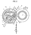
- FIG. 2 is a vertical sectional view of the fixing device 20 illustrating a heat shield 27 incorporated therein that is situated at a shield position.
- FIG. 3 is a vertical sectional view of the fixing device 20 illustrating the heat shield 27 situated at a retracted position.
- FIG. 4 is a block diagram of the image forming apparatus 1.
- the fixing device 20 (e.g., a fuser) includes a fixing belt 21 serving as a fixing rotary body or an endless belt formed into a loop and rotatable in a rotation direction R3; a pressing roller 22 serving as an opposed body disposed opposite an outer circumferential surface of the fixing belt 21 to separably contact the fixing belt 21 and rotatable in a rotation direction R4 counter to the rotation direction R3 of the fixing belt 21; a halogen heater pair 23 serving as a heater disposed inside the loop formed by the fixing belt 21 and heating the fixing belt 21; a nip formation assembly 24 disposed inside the loop formed by the fixing belt 21 and pressing against the pressing roller 22 via the fixing belt 21 to form a fixing nip N between the fixing belt 21 and the pressing roller 22; a stay 25 serving as a support disposed inside the loop formed by the fixing belt 21 and contacting and supporting the nip formation assembly 24; a reflector 26 disposed inside the loop formed by the fixing belt 21 and reflecting light
- the fixing belt 21 and the components disposed inside the loop formed by the fixing belt 21, that is, the halogen heater pair 23, the nip formation assembly 24, the stay 25, the reflector 26, and the heat shield 27, may constitute a belt unit 21U separably coupled with the pressing roller 22.
- the fixing belt 21 is a thin, flexible endless belt or film.
- the fixing belt 21 is constructed of a base layer constituting an inner circumferential surface of the fixing belt 21 and a release layer constituting the outer circumferential surface of the fixing belt 21.
- the base layer is made of metal such as nickel and SUS stainless steel or resin such as polyimide (PI).
- the release layer is made of tetrafluoroethylene-perfluoroalkylvinylether copolymer (PFA), polytetrafluoroethylene (PTFE), or the like.
- PFA tetrafluoroethylene-perfluoroalkylvinylether copolymer
- PTFE polytetrafluoroethylene
- an elastic layer made of rubber such as silicone rubber, silicone rubber foam, and fluoro rubber may be interposed between the base layer and the release layer.
- the fixing belt 21 does not incorporate the elastic layer, the fixing belt 21 has a decreased thermal capacity that improves fixing property of being heated to a predetermined fixing temperature quickly.
- the pressing roller 22 and the fixing belt 21 sandwich and press a toner image T on a recording medium P passing through the fixing nip N, slight surface asperities of the fixing belt 21 may be transferred onto the toner image T on the recording medium P, resulting in variation in gloss of the solid toner image T.
- the fixing belt 21 incorporates the elastic layer having a thickness not smaller than 100 micrometers.
- the elastic layer having the thickness not smaller than 100 micrometers elastically deforms to absorb slight surface asperities of the fixing belt 21, preventing variation in gloss of the toner image T on the recording medium P.
- the fixing belt 21 is designed to be thin and have a reduced loop diameter so as to decrease the thermal capacity thereof.
- the fixing belt 21 is constructed of the base layer having a thickness in a range of from 20 micrometers to 50 micrometers; the elastic layer having a thickness in a range of from 100 micrometers to 300 micrometers; and the release layer having a thickness in a range of from 10 micrometers to 50 micrometers.
- the fixing belt 21 has a total thickness not greater than 1 mm.
- a loop diameter of the fixing belt 21 is in a range of from 20 mm to 40 mm.
- the fixing belt 21 may have a total thickness not greater than 0.20 mm and preferably not greater than 0.16 mm. Additionally, the loop diameter of the fixing belt 21 may not be greater than 30 mm.
- the pressing roller 22 is constructed of a metal core 22a; an elastic layer 22b coating the metal core 22a and made of silicone rubber foam, silicone rubber, fluoro rubber, or the like; and a release layer 22c coating the elastic layer 22b and made of PFA, PTFE, or the like.
- a pressurization assembly described below presses the pressing roller 22 against the nip formation assembly 24 via the fixing belt 21.
- the pressing roller 22 pressingly contacting the fixing belt 21 deforms the elastic layer 22b of the pressing roller 22 at the fixing nip N formed between the pressing roller 22 and the fixing belt 21, thus creating the fixing nip N having a predetermined length in the recording medium conveyance direction A1.
- the pressing roller 22 is pressed against the fixing belt 21.
- the pressing roller 22 may merely contact the fixing belt 21 with no pressure therebetween.
- a fixing motor 92 depicted in FIG. 4 that is disposed inside the image forming apparatus 1 serves as a driver that drives and rotates the pressing roller 22.
- a driving force of the fixing motor 92 is transmitted from the pressing roller 22 to the fixing belt 21 at the fixing nip N, thus rotating the fixing belt 21 by friction between the pressing roller 22 and the fixing belt 21.
- the fixing motor 92 may also be connected to the fixing belt 21 to drive and rotate the fixing belt 21.
- the pressing roller 22 is a solid roller.
- the pressing roller 22 may be a hollow roller.
- a heater such as a halogen heater may be disposed inside the hollow roller.
- the elastic layer 22b may be made of solid rubber.
- the elastic layer 22b may be made of sponge rubber. The sponge rubber is more preferable than the solid rubber because it has an increased insulation that draws less heat from the fixing belt 21.
- the halogen heater pair 23 is situated inside the loop formed by the fixing belt 21 and upstream from the fixing nip N in the recording medium conveyance direction A1.
- the halogen heater pair 23 is situated lower than and upstream from a hypothetical line L passing through a center Q of the fixing nip N in the recording medium conveyance direction A1 and an axis O of the pressing roller 22 in FIG. 2 .
- the power supply situated inside the image forming apparatus 1 supplies power to the halogen heater pair 23 so that the halogen heater pair 23 heats the fixing belt 21. As shown in FIG.
- a controller 90 e.g., a processor
- CPU central processing unit
- RAM random-access memory
- ROM read-only memory
- the controller 90 may be operatively connected to a temperature sensor disposed opposite the pressing roller 22 to detect the temperature of the pressing roller 22 so that the controller 90 predicts the temperature of the fixing belt 21 based on the temperature of the pressing roller 22 detected by the temperature sensor, thus controlling the halogen heater pair 23.
- two halogen heaters constituting the halogen heater pair 23 are situated inside the loop formed by the fixing belt 21.
- one halogen heater or three or more halogen heaters may be situated inside the loop formed by the fixing belt 21 according to the sizes of the recording media P available in the image forming apparatus 1.
- an induction heater, a resistance heat generator, a carbon heater, or the like may be employed as a heater that heats the fixing belt 21.
- the nip formation assembly 24 includes a base pad 241 and a slide sheet 240 (e.g., a low-friction sheet) covering an outer surface of the base pad 241.
- the slide sheet 240 covers an opposed face of the base pad 241 disposed opposite the fixing belt 21.
- a longitudinal direction of the base pad 241 is parallel to an axial direction of the fixing belt 21 or the pressing roller 22.
- the base pad 241 receives pressure from the pressing roller 22 to define the shape of the fixing nip N.
- the fixing nip N is planar in cross-section as shown in FIG. 2 .
- the fixing nip N may be concave with respect to the pressing roller 22 or have other shapes.
- the slide sheet 240 reduces friction between the base pad 241 and the fixing belt 21 sliding thereover as the fixing belt 21 rotates in the rotation direction R3.
- the base pad 241 may be made of a low friction material. In this case, the slide sheet 240 is not interposed between the base pad 241 and the fixing belt 21.
- the base pad 241 is made of a heat resistant material resistant against temperatures of 200 degrees centigrade or higher to prevent thermal deformation of the nip formation assembly 24 by temperatures in a fixing temperature range desirable to fix the toner image T on the recording medium P, thus retaining the shape of the fixing nip N and quality of the toner image T formed on the recording medium P.
- the base pad 241 is also made of a rigid material having an increased mechanical strength.
- the base pad 241 is made of resin such as polyether sulfone (PES), polyphenylene sulfide (PPS), liquid crystal polymer (LCP), polyether nitrile (PEN), polyamide imide (PAI), polyether ether ketone (PEEK), or the like.
- the base pad 241 may be made of metal, ceramic, or the like.
- the base pad 241 is mounted on and supported by the stay 25. Accordingly, even if the base pad 241 receives pressure from the pressing roller 22, the base pad 241 is not bent by the pressure and therefore produces a uniform nip width throughout the entire width of the pressing roller 22 in the axial direction thereof.
- the stay 25 is made of metal having an increased mechanical strength, such as stainless steel and iron, to prevent bending of the nip formation assembly 24.
- the reflector 26 is mounted on and supported by the stay 25 and disposed opposite the halogen heater pair 23.
- the reflector 26 reflects light or heat radiated from the halogen heater pair 23 thereto onto the fixing belt 21, suppressing conduction of heat from the halogen heater pair 23 to the stay 25.
- the reflector 26 facilitates efficient heating of the fixing belt 21, saving energy.
- the reflector 26 is made of aluminum, stainless steel, or the like. If the reflector 26 includes an aluminum base treated with silver-vapor-deposition to decrease radiation and increase reflectance of light, the reflector 26 facilitates heating of the fixing belt 21.
- the heat shield 27 is a metal plate, having a thickness in a range of from 0.1 mm to 1.0 mm, curved in a circumferential direction of the fixing belt 21 along the inner circumferential surface thereof.
- the heat shield 27 is interposed between the halogen heater pair 23 and the fixing belt 21 and movable in the circumferential direction of the fixing belt 21. As shown in FIG.
- a circumference of the fixing belt 21 is divided into two sections: a circumferential, direct heating span ⁇ where the halogen heater pair 23 is disposed opposite and heats the fixing belt 21 directly and a circumferential, indirect heating span ⁇ where the halogen heater pair 23 is disposed opposite the fixing belt 21 indirectly via the components other than the heat shield 27 (e.g., the reflector 26, the stay 25, the nip formation assembly 24, and the like) that are mounted on a pair of side plates of the fixing device 20.
- the heat shield 27 moves to the shield position shown in FIG. 2 where the heat shield 27 is disposed opposite the halogen heater pair 23 directly in the direct heating span ⁇ to shield the fixing belt 21 from the halogen heater pair 23.
- the shield position may be located at one or more positions within the direct heating span ⁇ .
- the heat shield 27 moves to the retracted position shown in FIG. 3 where the heat shield 27 retracts from the direct heating span ⁇ to the indirect heating span ⁇ and therefore is disposed opposite the halogen heater pair 23 indirectly. That is, the heat shield 27 is entirely behind the reflector 26 and the stay 25 and therefore disposed opposite the halogen heater pair 23 via the reflector 26 and the stay 25. Thus, the heat shield 27 does not shield the fixing belt 21 from the halogen heater pair 23.
- the heat shield 27 As the heat shield 27 moves in the circumferential direction of the fixing belt 21, the heat shield 27 changes the area of the direct heating span ⁇ on the fixing belt 21, adjusting an amount of heat radiated from the halogen heater pair 23 to the fixing belt 21.
- the heat shield 27 is made of a heat resistant material, for example, metal such as aluminum, iron, and stainless steel or ceramic.
- the recording medium sensor 29 is disposed downstream from the fixing nip N in a recording medium conveyance direction A2 to detect the recording medium P discharged from the fixing nip N.
- the recording medium sensor 29 may be a photo interrupter.
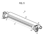
- FIG. 5 is a partial perspective view of the fixing device 20.
- the flanges 40 serving as a belt holder are inserted into both lateral ends of the fixing belt 21 in the axial direction thereof, respectively, to rotatably support the fixing belt 21.
- Both lateral ends of the flanges 40, the halogen heater pair 23, and the stay 25 in the axial direction of the fixing belt 21 are mounted on and supported by the pair of side plates of the fixing device 20, respectively.
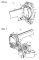
- FIG. 6 is a partial perspective view of the fixing device 20 illustrating one lateral end of the heat shield 27 in the axial direction of the fixing belt 21.
- the heat shield 27 is supported by an arcuate slider 41 rotatably or slidably attached to the flange 40.
- a projection 27a disposed at each lateral end of the heat shield 27 in the axial direction of the fixing belt 21 is inserted into a hole 41 a produced in the slider 41.
- the heat shield 27 is attached to the slider 41.
- the slider 41 includes a tab 41b projecting inboard in the axial direction of the fixing belt 21 toward the heat shield 27.
- the slider 41 As the tab 41b of the slider 41 is inserted into an arcuate groove 40a produced in the flange 40, the slider 41 is slidably movable in the groove 40a. Accordingly, the heat shield 27, together with the slider 41, is rotatable or movable in a circumferential direction of the flange 40.
- the flange 40 and the slider 41 are made of resin.
- FIG. 6 illustrates the support mechanism that supports the heat shield 27 at one lateral end thereof in the axial direction of the fixing belt 21
- another lateral end of the heat shield 27 in the axial direction of the fixing belt 21 is also supported by the support mechanism shown in FIG. 6 .
- another lateral end of the heat shield 27 is also rotatably or movably supported by the slider 41 slidable in the groove 40a of the flange 40.
- FIG. 7 is a partial perspective view of the fixing device 20 illustrating the heat shield driver 46.
- the heat shield driver 46 includes a motor 42 serving as a driving source and a plurality of gears 43, 44, and 45 constituting a gear train.
- the gear 43 serving as one end of the gear train is connected to the motor 42.
- the gear 45 serving as another end of the gear train is connected to a gear 41c produced on the slider 41 along a circumferential direction thereof.
- the motor 42 is driven, a driving force is transmitted from the motor 42 to the gear 41c of the slider 41 through the gear train, that is, the gears 43 to 45, thus rotating the heat shield 27 supported by the slider 41 forward in a first rotation direction from the indirect heating span ⁇ to the direct heating span ⁇ and backward in a second rotation direction from the direct heating span ⁇ to the indirect heating span ⁇ .
- the motor 42 is a stepping motor.
- the position of the heat shield 27 is adjusted by changing the number of driving pulses.
- the motor 42 may be a direct current (DC) motor or the like.
- FIG. 8 is a schematic diagram of the fixing device 20 illustrating the halogen heater pair 23, the heat shield 27, and recording media of various sizes.
- the heat shield 27 includes a pair of shield portions 48, constituting both lateral ends of the heat shield 27 in an axial direction, that is, the longitudinal direction, thereof; a bridge 49 bridging the shield portions 48 in the axial direction of the heat shield 27; and a recess 50 defined by the shield portions 48 and the bridge 49, and in turn itself defining an inboard edge of each shield portion 48.
- the shield portions 48 are disposed opposite both lateral ends of the halogen heater pair 23 in the axial direction of the fixing belt 21, respectively, to shield both lateral ends of the fixing belt 21 in the axial direction thereof from the halogen heater pair 23.
- the recess 50 between the pair of shield portions 48 in the axial direction of the heat shield 27 does not shield the fixing belt 21 from the halogen heater pair 23 and therefore allows light radiated from the halogen heater pair 23 to irradiate the fixing belt 21.
- each shield portion 48 includes a circumferentially straight edge 51 extending parallel to the circumferential direction of the heat shield 27 in which the heat shield 27 pivots and a sloped edge 52 angled relative to the circumferentially straight edge 51.
- the sloped edge 52 is contiguous to the circumferentially straight edge 51 substantially in a shield direction Y in which the heat shield 27 moves from the retracted position shown in FIG. 3 to the shield position shown in FIG. 2 .
- the sloped edge 52 is angled outboard from the circumferentially straight edge 51 substantially in the shield direction Y such that an interval between the sloped edge 52 and another sloped edge 52 increases.
- the recess 50 has a uniform, decreased width defined by the circumferentially straight edges 51 in the axial direction of the heat shield 27 and an increased width defined by the sloped edges 52 in the axial direction of the heat shield 27 that increases gradually in the shield direction Y.
- the halogen heater pair 23 has a plurality of heat generators having different lengths in the axial direction of the fixing belt 21 and being situated at different positions in the axial direction of the fixing belt 21 to heat different axial spans on the fixing belt 21 according to the size of the recording medium P.
- the halogen heater pair 23 is constructed of the lower halogen heater 23 having a center heat generator 23 a disposed opposite a center of the fixing belt 21 in the axial direction thereof and the upper halogen heater 23 having lateral end heat generators 23b disposed opposite both lateral ends of the fixing belt 21 in the axial direction thereof, respectively.
- the center heat generator 23a spans a conveyance span S2 corresponding to a width W2 of a medium recording medium P2 in the axial direction of the fixing belt 21.
- the lateral end heat generators 23b together with the center heat generator 23 a, span a conveyance span S3 corresponding to a width W3 of a large recording medium P3 greater than the width W2 of the medium recording medium P2 and a conveyance span S4 corresponding to a width W4 of an extra-large recording medium P4 greater than the width W3 of the large recording medium P3.
- Each circumferentially straight edge 51 is situated inboard from and in proximity to an edge of the conveyance span S3 corresponding to the width W3 of the large recording medium P3 in the axial direction of the fixing belt 21.
- Each sloped edge 52 overlaps the edge of the conveyance span S3.
- the medium recording medium P2 is a letter size recording medium having a width W2 of 215.9 mm or an A4 size recording medium having a width W2 of 210 mm.
- the large recording medium P3 is a double letter size recording medium having a width W3 of 279.4 mm or an A3 size recording medium having a width W3 of 297 mm.
- the extra-large recording medium P4 is an A3 extension size recording medium having a width W4 of 329 mm.
- the medium recording medium P2, the large recording medium P3, and the extra-large recording medium P4 may include recording media of other sizes.
- the medium, large, and extra-large sizes mentioned herein are relative terms. Hence, instead of the medium, large, and extra-large sizes, small, medium, and large sizes may be used.
- FIG. 9 is a partial schematic diagram of the fixing device 20.
- the controller 90 depicted in FIG. 4 turns on the center heat generator 23 a to heat the conveyance span S2 of the fixing belt 21 corresponding to the width W2 of the medium recording medium P2.
- the controller 90 turns on the lateral end heat generators 23b as well as the center heat generator 28a to heat the conveyance span S4 of the fixing belt 21 corresponding to the width W4 of the extra-large recording medium P4.
- the halogen heater pair 23 is configured to heat the conveyance span S2 corresponding to the width W2 of the medium recording medium P2 and the conveyance span S4 corresponding to the width W4 of the extra-large recording medium P4. Accordingly, if the center heat generator 23 a is turned on as the large recording medium P3 is conveyed over the fixing belt 21, the center heat generator 23 a does not heat each outboard span S2a outboard from the conveyance span S2 in the axial direction of the fixing belt 21. Consequently, the large recording medium P3 is not heated throughout the entire width W3 thereof.
- the lateral end heat generators 23b and the center heat generator 23a may heat both outboard spans S3a outboard from the conveyance span S3 in the axial direction of the fixing belt 21 corresponding to the width W3 of the large recording medium P3. If the large recording medium P3 is conveyed over the fixing belt 21 while the lateral end heat generators 23b and the center heat generator 23a are turned on, the lateral end heat generators 23b may heat both outboard spans S3a outboard from the conveyance span S3 in the axial direction of the fixing belt 21 corresponding to the width W3 of the large recording medium P3, resulting in overheating of the fixing belt 21 in the outboard spans S3a.
- the heat shield 27 moves to the shield position as shown in FIG. 9 .
- the shield portions 48 of the heat shield 27 shield the fixing belt 21 in a span in proximity to both side edges of the large recording medium P3 and the outboard spans S3a, thus suppressing overheating of the fixing belt 21 in the outboard spans S3a where the large recording medium P3 is not conveyed.
- the fixing device 20 performs a fixing job precisely by moving the heat shield 27 to the shield position shown in FIG. 2 at a proper time without decreasing the rotation speed of the fixing belt 21 and the pressing roller 22 to convey the large recording medium P3.
- the controller 90 moves the heat shield 27 to the retracted position shown in FIG. 3 where the heat shield 27 is disposed opposite the indirect heating span ⁇ on the fixing belt 21.
- each shield portion 48 includes the sloped edge 52 as shown in FIG. 8 , as the rotation angle of the heat shield 27 changes, the shield portions 48 shield the fixing belt 21 from the lateral end heat generators 23b in a variable area. For example, if the number of recording media conveyed through the fixing nip N and a conveyance time for which the recording media are conveyed through the fixing nip N increase, the fixing belt 21 is subject to overheating in a non-conveyance span (e.g., the outboard spans S2a and S3a) thereof.
- a non-conveyance span e.g., the outboard spans S2a and S3a
- the controller 90 moves the heat shield 27 in the shield direction Y to the shield position shown in FIG. 2 where the shield portions 48 are disposed opposite the lateral end heat generators 23b, respectively, suppressing overheating of the fixing belt 21 precisely.
- the temperature sensor 28 for detecting the temperature of the fixing belt 21 is disposed opposite an axial span on the fixing belt 21 where the fixing belt 21 is subject to overheating.
- the temperature sensor 28 is disposed opposite each outboard span S3a outboard from the conveyance span S3 corresponding to the width W3 of the large recording medium P3 because the fixing belt 21 is subject to overheating in the outboard span S3a. Since the fixing belt 21 is subject to overheating by light radiated from the lateral end heat generators 23b, the temperature sensors 28 are disposed opposite the lateral end heat generators 23b, respectively.
- the temperature sensor 28 may be located at other positions, for example, the temperature sensor 28 may be disposed opposite a center of the fixing belt 21 in the axial direction thereof.
- the number of the temperature sensors 28 may be changed arbitrarily. For example, three or more temperature sensors 28 may be aligned in the axial direction of the fixing belt 21.
- FIG. 10 is a schematic diagram of the fixing device 20S.
- FIG. 11 is a partial schematic diagram of the fixing device 20S.
- the heat shield 27S includes a pair of shield portions 48S disposed at both lateral ends of the heat shield 27S in an axial direction thereof, respectively.
- Each of the shield portions 48S has two steps.
- each shield portion 48S includes an outboard, small shield section 48a having a decreased length in a longitudinal direction of the heat shield 27S parallel to the axial direction thereof and an inboard, great shield section 48b having an increased length in the longitudinal direction of the heat shield 27S.
- the bridge 49 bridges the great shield section 48b of one shield portion 48S serving as a primary shield portion situated at one lateral end of the heat shield 27S and the great shield section 48b of another shield portion 48S serving as a secondary shield portion situated at another lateral end of the heat shield 27S in the axial direction thereof.
- the small shield section 48a is contiguous to the great shield section 48b substantially in the shield direction Y.
- a sloped edge 52a that is, an inboard edge of the small shield section 48a in the axial direction of the heat shield 27S, is disposed opposite another sloped edge 52a, that is, an inboard edge of another small shield section 48a in the axial direction of the heat shield 27S.
- a sloped edge 52b that is, an inboard edge of the great shield section 48b in the axial direction of the heat shield 27S, is disposed opposite another sloped edge 52b, that is, an inboard edge of another great shield section 48b in the axial direction of the heat shield 27S.
- the two sloped edges 52b of the great shield sections 48b are angled relative to the bridge 49 such that an interval between the two sloped edges 52b in the axial direction of the heat shield 27S increases gradually in the shield direction Y.
- the two sloped edges 52a of the small shield sections 48a are angled relative to the bridge 49 such that an interval between the two sloped edges 52a in the axial direction of the heat shield 27S increases gradually in the shield direction Y.
- the heat shield 27S does not incorporate the circumferentially straight edges 51.
- the small recording medium P1 includes a postcard having a width of 100 mm.
- the medium recording medium P2 includes an A4 size recording medium having a width of 210 mm.
- the large recording medium P3 includes an A3 size recording medium having a width of 297 mm.
- the extra-large recording medium P4 includes an A3 extension size recording medium having a width of 329 mm.
- the small recording medium P1, the medium recording medium P2, the large recording medium P3, and the extra-large recording medium P4 may include recording media of other sizes.
- a width W1 of the small recording medium P1 is smaller than the length of the center heat generator 23a in a longitudinal direction of the halogen heater pair 23 parallel to the axial direction of the heat shield 27S.
- the sloped edge 52b of the great shield section 48b overlaps a side edge of the small recording medium P1.
- the sloped edge 52a of the small shield section 48a overlaps a side edge of the large recording medium P3.
- the center heat generator 23a As the small recording medium P1 is conveyed through the fixing nip N, the center heat generator 23a is turned on. However, since the center heat generator 23a heats the conveyance span S2 on the fixing belt 21 corresponding to the width W2 of the medium recording medium P2 that is greater than the width W1 of the small recording medium P1, the controller 90 moves the heat shield 27S to the shield position shown in FIG. 11 . At the shield position shown in FIG. 11 , each great shield section 48b of the heat shield 27S shields the fixing belt 21 from the center heat generator 23a in an outboard span S1a outboard from a conveyance span S1 corresponding to the width W1 of the small recording medium P1 in the axial direction of the fixing belt 21. Accordingly, the fixing belt 21 does not overheat in each outboard span S1a where the small recording medium P1 is not conveyed over the fixing belt 21.
- the controller 90 performs a control for controlling the halogen heater pair 23 and the heat shield 27S that is similar to the control for controlling the halogen heater pair 23 and the heat shield 27 described above.
- each small shield section 48a of the heat shield 27S shields the fixing belt 21 from the halogen heater pair 23 as each shield portion 48 of the fixing device 20 does.
- the small shield section 48a and the great shield section 48b have the sloped edges 52a and 52b, respectively. Accordingly, by changing the rotation angled position of the heat shield 27S, the controller 90 changes the span on the fixing belt 21 shielded from the center heat generator 23a and the lateral end heat generators 23b of the halogen heater pair 23 by the small shield section 48a and the great shield section 48b of each shield portion 48S.
- FIG. 12A is a vertical sectional view of the fixing device 20 illustrating the pressurization assembly 60 separating the pressing roller 22 from the fixing belt 21.
- FIG. 12B is a vertical sectional view of the fixing device 20 illustrating the pressurization assembly 60 pressing the pressing roller 22 against the fixing belt 21.
- the pressurization assembly 60 presses the pressing roller 22 against the fixing belt 21 to form the fixing nip N between the pressing roller 22 and the fixing belt 21.
- the pressurization assembly 60 releases pressure between the pressing roller 22 and the fixing belt 21.
- the pressurization assembly 60 separates the pressing roller 22 from the fixing belt 21 or brings the pressing roller 22 into contact with the fixing belt 21 with no pressure therebetween.
- the pressurization assembly 60 includes a mechanism for detecting whether or not the pressing roller 20 presses against the fixing belt 21 at the fixing nip N.
- the pressurization assembly 60 includes a lever 61, a cam 62, a biasing member 63 (e.g., a tension spring), a feeler 64 serving as a detected member, and a sensor 65 serving as a detector.
- the lever 61 is pivotably mounted on a shaft O1 at one end of the lever 61 in a longitudinal direction thereof. Another end of the lever 61 in the longitudinal direction thereof contacts an outer circumferential surface of the cam 62.
- the lever 61 in the longitudinal direction thereof contacts the metal core 22a of the pressing roller 22 that projects outboard from the elastic layer 22b and the release layer 22c depicted in FIG. 2 at a lateral end of the pressing roller 22 in the axial direction thereof.
- the cam 62 is pivotably supported by an eccentric shaft 02 and is driven and rotated by a driver (e.g., a motor).
- the lever 61 is pressed against the outer circumferential surface of the cam 62 by resilience from the biasing member 63.
- the pressing roller 22 is supported by the side plates of the fixing device 20 such that the pressing roller 22 is slidable horizontally in FIGS. 12A and 12B to press against the fixing belt 21 and release pressure between the fixing belt 21 and the pressing roller 22.
- FIG. 12A as the outer circumferential surface of a semicircle having a decreased diameter of the cam 62 contacts the lever 61, the resilience generated by the biasing member 63 biases the lever 61 in a direction to separate from the metal core 22a of the pressing roller 22. Accordingly, the pressing roller 22 moves in a direction to separate from the fixing belt 21, thus exerting no pressure to the fixing belt 21.
- FIG. 12A as the outer circumferential surface of a semicircle having a decreased diameter of the cam 62 contacts the lever 61, the resilience generated by the biasing member 63 biases the lever 61 in a direction to separate from the metal core 22a of the pressing roller 22. Accordingly, the pressing roller 22 moves in a direction to separate from the fixing belt 21, thus exerting no pressure to the
- the feeler 64 is substantially formed in a semicircle pivotable about the shaft 02 in accordance with rotation of the cam 62. As shown in FIG. 12A , as the pressing roller 22 contacts the fixing belt 21 with no pressure therebetween or is isolated from the fixing belt 21, the feeler 64 overlaps the sensor 65 to shield the sensor 65 from light.
- the sensor 65 is a photo interrupter, for example. As the feeler 64 enters a gap between a light emitter and a light receiver of the sensor 65 to shield the light receiver from light emitted from the light emitter, the sensor 65 outputs a high signal to the controller 90 depicted in FIG. 4 that is operatively connected to the sensor 65.
- the sensor 65 Conversely, as the feeler 64 exits from the gap between the light emitter and the light receiver of the sensor 65 to allow the light emitted from the light emitter to reach the light receiver, the sensor 65 outputs a low signal to the controller 90. Accordingly, as the sensor 65 outputs the high signal, the controller 90 determines that the pressing roller 22 contacts the fixing belt 21 with no pressure therebetween or is isolated from the fixing belt 21. Conversely, as the sensor 65 outputs the low signal, the controller 90 determines that the pressing roller 22 presses against the fixing belt 21.
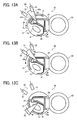
- the fixing devices 20 and 20S include a position detector 53 that detects the rotation angled position of the heat shields 27 and 27S as shown in FIGS. 13A, 13B, and 13C .
- FIG. 13A is a vertical sectional view of the fixing device 20 illustrating the position detector 53 situated at a home position.
- FIG. 13B is a vertical sectional view of the fixing device 20 illustrating the position detector 53 situated at a reference position.
- FIG. 13C is a vertical sectional view of the fixing device 20 illustrating the position detector 53 situated at the shield position.
- the position detector 53 detects the rotation angled position of the heat shield 27.
- the position detector 53 includes a single feeler 54 serving as a detected member and two sensors that detect the feeler 54, that is, a home position sensor 55 and an angle sensor 56.
- the feeler 54 is substantially formed in a fan or a triangle pivotable forward in a first pivot direction X1 and backward in a second pivot direction X2 in accordance with movement of the heat shield 27 through a linkage.
- the home position sensor 55 and the angle sensor 56 are mounted on a frame of the fixing device 20 such that the home position sensor 55 is isolated from the angle sensor 56 in the second pivot direction X2 of the feeler 54.
- Each of the home position sensor 55 and the angle sensor 56 is a photo interrupter constructed of a light emitter and a light receiver, for example.
- the home position sensor 55 situated upstream from the angle sensor 56 in the rotation direction R3 of the fixing belt 21 serves as a home position detector that detects a home position of the heat shield 27.
- the angle sensor 56 serves as a rotation angle controller that controls the rotation angle of the heat shield 27.
- the upstream edge 54a of the feeler 54 shields the light receiver of the home position sensor 55 from light emitted from the light emitter of the home position sensor 55.
- the angle sensor 56 is positioned relative to the home position sensor 55 such that a phase angle formed by the angle sensor 56 with the home position sensor 55 in the second pivot direction X2 of the feeler 54 is greater than a central angle A54 of the feeler 54.
- the heat shield 27 does not shield the fixing belt 21 from the halogen heater pair 23 and allows the halogen heater pair 23 to heat the fixing belt 21 in the increased direct heating span ⁇ as shown in FIG. 3 . Further, as the heat shield 27 is at the home position shown in FIG. 13A , the heat shield 27 is at an upstream end of the movable span thereof in the rotation direction R3 of the fixing belt 21. Hence, during a print job, the heat shield 27 does not move beyond the home position shown in FIG. 13A in the backward second pivot direction X2.
- the controller 90 determines that the heat shield 27 is at the home position. Simultaneously, the angle sensor 56 outputs a low signal.
- the heat shield 27 moves from the home position shown in FIG. 13A in the forward first pivot direction X1 of the feeler 54, that is, the rotation direction R3 of the fixing belt 21, a downstream edge 54b of the feeler 54 in the rotation direction R3 of the fixing belt 21 overlaps the angle sensor 56 as shown in FIG. 13B , shielding the light receiver of the angle sensor 56 from light emitted from the light emitter of the angle sensor 56. Accordingly, the signal output by the angle sensor 56 switches from low to high.
- the position of the heat shield 27 shown in FIG. 13B defines the reference position, that is, a zero point. As the motor 42 depicted in FIG. 7 rotates forward for a predetermined number of pulses, the heat shield 27 moves from the reference position shown in FIG.
- the reference position of the heat shield 27 is downstream from the home position thereof in the forward first pivot direction X1, that is, the rotation direction R3 of the fixing belt 21. Additionally, the home position of the heat shield 27 is set to a position where, as the heat shield 27 moves between the home position and the reference position in the forward first pivot direction X1 and the backward second pivot direction X2, the position detector 53 detects that the heat shield 27 reaches the reference position and the home position.
- a terminal of the heat shield 27 movable in the circumferential direction of the fixing belt 21 is determined based on the distance or the rotation angle from the reference position of the heat shield 27 by open loop control. Accordingly, open loop control simplifies the structure of the position detector 53 compared to closed loop control in which the controller 90 drives and rotates the motor 42 based on feedback of the position of the heat shield 27 and halts the heat shield 27 after the controller 90 determines that the heat shield 27 reaches the shield position.
- the heat shield 27 pivots in the forward first pivot direction X1 farther, the area of the fixing belt 21 shielded by the heat shield 27 from the halogen heater pair 23 increases in the direct heating span ⁇ . That is, as the heat shield 27 pivots in the forward first pivot direction X1 farther, the area of the direct heating span ⁇ of the fixing belt 21 decreases. While the heat shield 27 moves between the home position shown in FIG. 13A and the reference position shown in FIG. 13B , the area of the fixing belt 21 shielded by the heat shield 27 from the halogen heater pair 23 in the direct heating span ⁇ is substantially zero. As the heat shield 27 moves from the reference position shown in FIG. 13B in the forward first pivot direction X1, the area of the direct heating span ⁇ of the fixing belt 21 decreases. As the heat shield 27 pivoting in the forward first pivot direction X1 halts at various shield positions, the area of the direct heating span ⁇ of the fixing belt 21 decreases stepwise.
- the controller 90 determines whether or not the heat shield 27 is at the home position shown in FIG. 13A .
- the controller 90 determines that the heat shield 27 is at the home position.
- the pressurization assembly 60 situated at a depressurization position shown in FIG.
- the heat shield 27 moves from the home position shown in FIG. 13A in the forward first pivot direction X1.
- the controller 90 drives the motor 42 for the number of pulses corresponding to the distance from the reference position to the target shield position, moving the heat shield 27 to the target shield position shown in FIG. 13C .
- a recording medium P bearing an unfixed toner image T is conveyed to the fixing nip N in the recording medium conveyance direction A1 such that the unfixed toner image T faces the fixing belt 21.
- the fixing belt 21 rotating in the rotation direction R3 and the pressing roller 22 rotating in the rotation direction R4 convey the recording medium P bearing the toner image T through the fixing nip N
- the fixing belt 21 and the pressing roller 22 apply heat and pressure to the recording medium P, fixing the toner image T on the recording medium P.
- the print job is finished.
- the recording medium P bearing the fixed toner image T is discharged from the fixing nip N in the recording medium conveyance direction A2.
- the separator separates the recording medium P from the fixing belt 21.
- the separated recording medium P is discharged by the output roller pair 13 depicted in FIG. 1 onto the outside of the image forming apparatus 1, that is, the output tray 14 where the recording medium P is stocked.
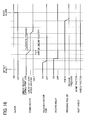
- FIG. 14 is a timing chart illustrating operation of the components of the fixing device 20.
- the controller 90 depicted in FIG. 4 determines that a trailing edge of the last recording medium P of the print job is discharged from the fixing nip N, the controller 90 sends a stop signal to the fixing device 20.
- the controller 90 turns off the halogen heater pair 23 and then a heater relay.
- the controller 90 causes the heat shield driver 46 to move and return the heat shield 27 to the home position shown in FIG. 13A .
- the controller 90 stops the fixing motor 92 depicted in FIG. 4 for driving and rotating the pressing roller 22, thus halting the pressing roller 22 and the fixing belt 21.
- the pressurization assembly 60 brings the pressing roller 22 into contact with the fixing belt 21 with no pressure therebetween as shown in FIG. 12A .
- the fixing belt 21 continues rotating for the preset time t1 after the heat shield 27 returns to the home position shown in FIG. 13A to prevent the fixing belt 21 from being heated locally by residual heat which may result in temperature variation of the fixing belt 21.
- the preset time t1 is determined by considering a time taken to even the temperature of the fixing belt 21. For example, end of the preset time t1 is determined based on the temperature of the fixing belt 21 detected by the temperature sensor 28 depicted in FIG. 2 or end of a predetermined time defines end of the preset time t1.
- the controller 90 returns the heat shield 27 to the home position as it does when the print job is completed safely, even if the fault occurs, the controller 90 may stop the fixing device 20 with delay. Accordingly, the fixing belt 21 may be heated by residual heat, causing temperature variation or uneven temperatures of the fixing belt 21 which may result in deformation of the fixing belt 21.
- FIG. 15 is a partial vertical sectional view of the fixing device 20 illustrating deformation of the fixing belt 21.
- the fixing belt 21 may deform in a deformation region Q1 due to temperature variation. If the recording medium P is jammed inside the fixing device 20, the jammed recording medium P may press the fixing belt 21 against an interior of the fixing belt 21. If the controller 90 moves and returns the heat shield 27 to the home position shown in FIG. 13A under such circumstance, since the heat shield 27 is configured to move in proximity to the inner circumferential surface of the fixing belt 21, the inner circumferential surface of the deformed fixing belt 21 may slide over the heat shield 27 while damaging each other or the motor 42 depicted in FIG. 7 may suffer from malfunction due to overload.
- the controller 90 controls the heat shield driver 46 to halt the heat shield 27 instantly to retain the heat shield 27 at a position where the heat shield 27 is situated at the time of the fault, not to move the heat shield 27 to other positions. Accordingly, even if the fixing belt 21 deforms as the fault occurs, the controller 91 prevents the deformed fixing belt 21 from sliding over the heat shield 27, reducing damage to the fixing belt 21, the heat shield 27, and the heat shield driver 46 that drives the heat shield 27.
- Operation of the fixing device 20 when the fault occurs varies depending on whether or not the recording medium sensor 29 depicted in FIG. 2 detects the recording medium P.
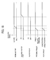
- FIG. 16 is a timing chart illustrating operation of the components of the fixing device 20 when the recording medium sensor 29 detects the recording medium P.
- the controller 90 Upon receipt of a fault detection signal indicating a fault occurring in the image forming apparatus 1, the controller 90 turns off the halogen heater pair 23 and then the heater relay. After the heater relay is turned off, the controller 90 controls the heat shield driver 46 to decrease the linear velocity of the fixing belt 21 rotating in the rotation direction R3 to convey the recording medium P to a decreased linear velocity, thus rotating the fixing belt 21 forward in the rotation direction R3 at the decreased linear velocity for a preset forward rotation time Ta. After the preset time Ta elapses, the controller 90 halts the fixing belt 21.
- an alarm 91 depicted in FIG. 4 that is provided in the image forming apparatus 1 issues an alarm that alarms a user about the fault occurring in the image forming apparatus 1.
- the alarm 91 is a notice that appears on a control panel disposed atop the image forming apparatus 1, an alarm lamp turned on as the fault occurs, an alarm or an audible alarm, or the like.
- the controller 90 prohibits the user from using the fixing device 20.
- the heat shield 27 is retained at the position where the heat shield 27 is situated when the fault occurs.
- the recording medium sensor 29 detects the recording medium P
- a leading edge of the recording medium P is discharged from the fixing nip N and separated from the fixing belt 21. Accordingly, even if the fixing belt 21 rotates forward further in the rotation direction R3 to convey the recording medium P in the recording medium conveyance direction A2 depicted in FIG. 2 , the recording medium P is not wound around the fixing belt 21.
- the processes described above select a stable operation to rotate the fixing belt 21 forward in the rotation direction R3 after the halogen heater pair 23 is turned off.
- the preset forward rotation time Ta of the fixing belt 21 is a time long enough for the entire circumferential length of the fixing belt 21 to pass through the fixing nip N to allow the recording medium P to draw heat from the fixing belt 21. Additionally, the preset forward rotation time Ta of the fixing belt 21 is long enough for the pressing roller 22 to draw heat from the fixing belt 21 after the recording medium P is discharged from the fixing nip N. For example, the preset forward rotation time Ta of the fixing belt 21 is equivalent to a time taken for the fixing belt 21 to rotate for one cycle. The fixing belt 21 is rotated forward in the rotation direction R3 at a decreased linear velocity to facilitate heat conduction from the fixing belt 21 to the recording medium P so as to reduce temperature variation of the fixing belt 21.
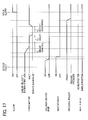
- FIG. 17 is a timing chart illustrating operation of the components of the fixing device 20 when the recording medium sensor 29 does not detect the recording medium P.
- the controller 90 depicted in FIG. 4 Upon receipt of a fault detection signal indicating a fault occurring in the image forming apparatus 1, the controller 90 depicted in FIG. 4 turns off the halogen heater pair 23 and then the heater relay. After the heater relay is turned off, the controller 90 performs brake control to the fixing motor 92 for a preset time Tb to halt the pressing roller 22 and the fixing belt 21. After forcefully halting the fixing motor 92 for a preset time Tc, the controller 90 rotates the fixing motor 92 backward for a preset backward rotation time Td and halts the fixing motor 92.
- the pressurization assembly 60 that has pressed the pressing roller 22 against the fixing belt 21 releases pressure between the pressing roller 22 and the fixing belt 21 as shown in FIG. 12A .
- the alarm 91 provided in the image forming apparatus 1 issues an alarm that alarms the user about the fault occurring in the image forming apparatus 1.
- the controller 90 prohibits the user from using the fixing device 20.
- the heat shield 27 is retained at the position where the heat shield 27 is situated when the fault occurs.
- the fixing belt 21 is rotated backward in a direction counter to the rotation direction R3 after the halogen heater pair 23 is turned off because the recording medium P may be wound around the fixing belt 21 if the fixing belt 21 rotates forward in the rotation direction R3. If the recording medium P is wound around the fixing belt 21, it is difficult for the user to remove the recording medium P from the fixing device 20. Moreover, if a rigid recording medium P such as thick paper is wound around the fixing belt 21, the rigid recording medium P may damage the fixing belt 21. To address this circumstance, the fixing belt 21 is rotated backward in the direction counter to the rotation direction R3 after the halogen heater pair 23 is turned off, thus preventing the recording medium P from being wound around the fixing belt 21.
- the recording medium sensor 29 detects the recording medium P
- the fixing motor 92 rotates backward
- the unshielded region on the direct heating span ⁇ of the fixing belt 21 which is not shielded by the heat shield 27 is heated by residual heat from the halogen heater pair 23.
- the controller 90 performs brake control to the fixing motor 92 and the fixing belt 21 rotates backward in the direction counter to the rotation direction R3
- the fixing belt 21 conveys the recording medium P through the fixing nip N in a direction counter to the recording medium conveyance direction A1 depicted in FIG. 2 . Accordingly, the recording medium P draws heat from the fixing belt 21, preventing substantial temperature variation and uneven temperatures of the fixing belt 21 and therefore preventing deformation of the fixing belt 21.
- the preset backward rotation time Td of the fixing belt 21 is equivalent to a time taken for the fixing belt 21 to rotate for one cycle. Due to a reason similar to the reason described above in the case in which the recording medium detector 29 detects the recording medium P, the fixing belt 21 is rotated backward in the direction counter to the rotation direction R3 at a decreased linear velocity.
- the controller 90 before rotating the fixing motor 92 backward, the controller 90 performs brake control to the fixing motor 92 and forcefully halts the fixing motor 92 so as to prevent breakage of the fixing motor 92 as the fixing motor 92 having rotated forward starts rotating backward. If the fixing motor 92 is capable of switching from forward rotation to backward rotation without brake control and forceful halting, it is not necessary for the controller 90 to perform brake control and forceful halting on the fixing motor 92.
- the controller 90 halts the fixing device 20 and the image forming apparatus 1 quickly regardless of whether or not the recording medium detector 29 detects the recording medium P, thus reducing damage to the components incorporated in the image forming apparatus 1. Additionally, the processes shown in FIGS. 16 and 17 prevent uneven temperatures of the fixing belt 21 and resultant deformation of the fixing belt 21. Even if the fixing belt 21 deforms, the halted heat shield 27 does not slide over the fixing belt 21, preventing abrasion of the heat shield 27 and the fixing belt 21.
- the pressurization assembly 60 having pressed the pressing roller 22 against the fixing belt 21 releases pressure between the pressing roller 22 and the fixing belt 21 after the fixing belt 21 halts. It is because, if the user tries to remove the jammed recording medium P from the fixing nip N while the pressing roller 22 presses against the fixing belt 21, the recording medium P being pulled from the fixing nip N may damage the fixing belt 21 and the pressing roller 22 or may be torn, hindering the user from removing the jammed recording medium P from the fixing device 20.
- the pressurization assembly 60 brings the pressing roller 22 into contact with the fixing belt 21 with no pressure therebetween or isolates the pressing roller 22 from the fixing belt 21 before the fixing belt 21 halts, the fixing belt 21 may slip and overheat locally, resulting in deformation of the fixing belt 21.
- the alarm 91 alarms the user about the fault after operation of all the components shown in FIGS. 16 and 17 is completed.
- the user opens an exterior cover of the image forming apparatus 1 and starts a process to eliminate a cause of the fault, for example, to remove the jammed recording medium P from the fixing nip N of the fixing device 20.
- an interlock switch is turned off for safety. Accordingly, all the drivers installed in the image forming apparatus 1 including the fixing motor 92 are halted forcefully.
- the user opens the exterior cover before the fixing motor 92 starts rotating forward and backward to dissipate heat and therefore the fixing belt 21 may be halted forcefully, resulting in substantial temperature variation of the fixing belt 21. Further, the pressing roller 22 and the fixing belt 21 are also halted forcefully while the pressing roller 22 presses against the fixing belt 21. Accordingly, if a recording medium P is sandwiched between the fixing belt 21 and the pressing roller 22, the user may pull the recording medium P with a substantial force which may damage the fixing belt 21 and the pressing roller 22. Further, the user may not remove the jammed recording medium P from the fixing nip N.
- the alarm 91 alarms the user about the fault after operation of all the components shown in FIGS. 16 and 17 is completed, that is, after the halogen heater pair 23 is turned off, the fixing belt 21 is rotated forward or backward, and the pressurization assembly 60 having pressed the pressing roller 22 against the fixing belt 21 releases pressure between the pressing roller 22 and the fixing belt 21, thus preventing the problems described above.
- FIG. 18 is a timing chart illustrating processes performed by the components of the fixing device 20 as the image forming apparatus 1 is turned on for recovery.
- the heat shield 27 Upon receipt of a recovery signal indicating the fault is eliminated, the heat shield 27 returns to the home position shown in FIG. 13A and at the same time the pressurization assembly 60 presses the pressing roller 22 against the fixing belt 21 as shown in FIG. 12B .
- the fixing motor 92 is driven to rotate the fixing belt 21 and then the heater relay and the halogen heater pair 23 are turned on, rendering the image forming apparatus 1 ready for an image forming operation.
- the heat shield 27 moves to the home position shown in FIG. 13A before the halogen heater pair 23 is turned on. It is because, if the halogen heater pair 23 is turned on while the heat shield 27 is retained at the position where the heat shield 27 is situated when the fault occurs, the heat shield 27 may shield the fixing belt 21 in a part of the direct heating span ⁇ thereof, causing substantial temperature variation and uneven temperatures of the fixing belt 21 which may result in deformation of the fixing belt 21. To address this circumstance, the halogen heater pair 23 is turned on while the heat shield 27 is at the home position, allowing the halogen heater pair 23 to heat the fixing belt 21 evenly throughout the direct heating span ⁇ thereof.
- the heat shield 27 returns to the home position shown in FIG. 13A and at the same time the pressurization assembly 60 presses the pressing roller 22 against the fixing belt 21.
- the heat shield 27 may return to the home position before or after the pressurization assembly 60 presses the pressing roller 22 against the fixing belt 21 as long as the heat shield 27 returns to the home position and the pressurization assembly 60 presses the pressing roller 22 against the fixing belt 21 before the fixing motor 92 starts rotation.
- FIG. 19 is a flowchart showing such processes.
- the controller 90 receives a recovery signal.
- the controller 90 controls the heat shield driver 46 to pivot the heat shield 27 in the backward second pivot direction X2, thus moving the heat shield 27 to the home position shown in FIG. 13A .
- the controller 90 determines whether or not the home position sensor 55 outputs a high signal. If the controller 90 determines that the home position sensor 55 does not output the high signal (NO in step S3), in step S4, the controller 90 determines whether or not the home position sensor 55 outputs the high signal when a preset time elapses after the controller 90 determines that the home position sensor 55 does not output the high signal in step S3.
- step S5 the controller 90 determines that a fault occurs and sends an alarm signal to the alarm 91.
- step S6 the alarm 91 issues an alarm that alarms the user about the fault.
- a fault may occur while the heat shield 27 is at the home position shown in FIG. 13A .
- the heat shield 27 is retained at the home position. Accordingly, as the image forming apparatus 1 is turned on for recovery, it is not necessary to move the heat shield 27, facilitating early detection of the heat shield 27 at the home position and resulting in quick recovery of the image forming apparatus 1.
- the present invention is not limited to the details of the exemplary embodiments described above, and various modifications and improvements are possible.
- a hollow tubular roller or a solid roller may be used as a fixing rotary body.
- the shape of the heat shields 27 and 27S is not limited to those shown in FIGS. 8 and 10 .
- the shield portion 48 of the heat shield 27 has a single step as shown in FIG. 8 and the shield portion 48S of the heat shield 27S has two steps as shown in FIG. 10
- a heat shield having three or more steps may be used according to the size of the recording medium P.
- the fixing devices 20 and 20S include a fixing rotary body (e.g., the fixing belt 21) rotatable in the rotation direction R3; a heater (e.g., the halogen heater pair 23) to heat the fixing rotary body; an opposed body (e.g., the pressing roller 22) contacting an outer circumferential surface of the fixing rotary body to form the fixing nip N therebetween through which a recording medium P is conveyed; a heat shield (e.g., the heat shields 27 and 27S) interposed between the heater and the fixing rotary body and movable in a circumferential direction of the fixing rotary body to shield the fixing rotary body from the heater in a variable circumferential direct heating span of the fixing rotary body where the heater is disposed opposite the fixing rotary body directly; a heat shield driver (e.g., the heat shield driver 46) connected to the heat shield to drive and move the heat shield; and a controller (e.
- a fixing rotary body e.g., the fixing belt 21
- the controller halts the fixing device quickly, reducing damage to the components including the fixing rotary body which are incorporated in the fixing device.
- the shield portions 48 and 48S are disposed at both lateral ends of the heat shields 27 and 27S in the longitudinal direction thereof, respectively.
- the shield portions 48 and 48S may be disposed at one lateral end of the heat shields 27 and 27S in the longitudinal direction thereof, respectively.
- the recording medium P is conveyed over the fixing belt 21 along one lateral edge of the fixing belt 21 in the axial direction thereof and the shield portions 48 and 48S are disposed in proximity to another lateral edge of the fixing belt 21 in the axial direction thereof.
- the fixing belt 21 serves as a fixing rotary body.
- a fixing roller or the like may be used as a fixing rotary body.
- the pressing roller 22 serves as an opposed body.
- a pressing belt or the like may be used as an opposed body.
Landscapes
- Physics & Mathematics (AREA)
- General Physics & Mathematics (AREA)
- Fixing For Electrophotography (AREA)
Abstract
Description
- Exemplary aspects of the present invention relate to an image forming apparatus and an image forming method, and more particularly, to an image forming apparatus for forming a toner image on a recording medium and an image forming method performed by the image forming apparatus.
- Related-art image forming apparatuses, such as copiers, facsimile machines, printers, or multifunction printers having two or more of copying, printing, scanning, facsimile, plotter, and other functions, typically form an image on a recording medium according to image data. Thus, for example, a charger uniformly charges a surface of a photoconductor; an optical writer emits a light beam onto the charged surface of the photoconductor to form an electrostatic latent image on the photoconductor according to the image data; a development device supplies toner to the electrostatic latent image formed on the photoconductor to render the electrostatic latent image visible as a toner image; the toner image is directly transferred from the photoconductor onto a recording medium or is indirectly transferred from the photoconductor onto a recording medium via an intermediate transfer belt; finally, a fixing device applies heat and pressure to the recording medium bearing the toner image to fix the toner image on the recording medium, thus forming the image on the recording medium.
- Such fixing device may include a fixing rotary body heated by a heater and an opposed body contacting the fixing rotary body to form a fixing nip therebetween through which a recording medium bearing a toner image is conveyed. As the fixing rotary body and the opposed body rotate and convey the recording medium bearing the toner image through the fixing nip, the fixing rotary body heated to a predetermined fixing temperature and the opposed body together heat and melt toner of the toner image, thus fixing the toner image on the recording medium.
- Since the recording medium passing through the fixing nip draws heat from the fixing rotary body, a temperature sensor detects the temperature of the fixing rotary body to maintain the fixing rotary body at a desired temperature. Conversely, at each lateral end of the fixing rotary body in an axial direction thereof, the recording medium is not conveyed over the fixing rotary body and therefore does not draw heat from the fixing rotary body. Accordingly, after a plurality of recording media is conveyed through the fixing nip continuously, a non-conveyance span situated at each lateral end of the fixing rotary body may overheat.
- To address this circumstance, the fixing device may incorporate a heat shield to shield the non-conveyance span of the fixing rotary body from the heater, thus preventing overheating of the fixing rotary body as disclosed by
JP-2008-058833-A JP-2008-139779-A - Incidentally, the image forming apparatus may stop urgently when a fault occurs, for example, when the recording medium is jammed between the fixing rotary body and the opposed body. When the fault occurs, the heat shield returns to the home position. Accordingly, the fixing device may stop with delay, resulting damage to the components including the fixing rotary body that are incorporated in the fixing device.
- It is a general object of the present invention to provide an improved and useful image forming apparatus in which the above-mentioned problems are eliminated. In order to achieve the above-mentioned object, there is provided an image forming apparatus according to
claim 1. Advantageous embodiments are defined by the dependent claims. Advantageously, the image forming apparatus includes a fixing device including a fixing rotary body rotatable in a predetermined direction of rotation and a heater disposed opposite and heating the fixing rotary body. An opposed body contacts the fixing rotary body with releasable pressure therebetween to form a fixing nip therebetween through which a recording medium is conveyed. A heat shield is interposed between the heater and the fixing rotary body and movable in a circumferential direction of the fixing rotary body to shield the fixing rotary body from the heater in a variable circumferential direct heating span of the fixing rotary body where the heater is disposed opposite the fixing rotary body directly. A controller is operatively connected to the heater and the heat shield to halt the heat shield instantly when a fault occurs during a print job. - Accordingly, even if the image forming apparatus stops urgently, the controller halts the fixing device quickly, reducing damage to the components including the fixing rotary body which are incorporated in the fixing device.
- The controller moves the heat shield to a home position where the heat shield is disposed opposite the heater indirectly when the fault is eliminated.
- The image forming apparatus further includes a recording medium detector operatively connected to the controller and disposed downstream from the fixing nip in a recording medium conveyance direction to detect the recording medium.
- The fixing rotary body rotates forward in the predetermined direction of rotation after the controller turns off the heater as the recording medium detector detects the recording medium when the fault occurs.
- When the fault occurs, the fixing rotary body rotates forward in the predetermined direction of rotation at a linear velocity slower than a linear velocity at which the fixing rotary body rotates during the print job.
- The pressure between the opposed body and the fixing rotary body is released after the fixing rotary body halts after the fixing rotary body rotates forward in the predetermined direction of rotation.
- The image forming apparatus further includes an alarm operatively connected to the controller to issue an alarm after the pressure between the opposed body and the fixing rotary body is released.
- The fixing rotary body rotates backward in a direction counter to the predetermined direction of rotation after the controller turns off the heater as the recording medium detector does not detect the recording medium when the fault occurs.
- When the fault occurs, the fixing rotary body rotates backward in the direction counter to the predetermined direction of rotation at a linear velocity slower than a linear velocity at which the fixing rotary body rotates during the print job.
- The pressure between the opposed body and the fixing rotary body is released after the fixing rotary body halts after the fixing rotary body rotates backward in the direction counter to the predetermined direction of rotation.
- The image forming apparatus further includes a position detector operatively connected to the controller and linked with the heat shield to detect a position of the heat shield.
- The position detector includes a feeler connected to the heat shield and pivotable in the circumferential direction of the fixing rotary body in accordance with movement of the heat shield; a home position sensor defining a home position where the heat shield is disposed opposite the heater indirectly to detect the feeler as the feeler overlaps the home position sensor; and an angle sensor disposed downstream from the home position sensor in the direction of rotation of the fixing rotary body to detect the feeler as the feeler overlaps the angle sensor. The angle sensor defines a reference position of the heat shield.
- Advantageously, an image forming method includes rotating a fixing rotary body forward at an increased linear velocity to convey a recording medium through a fixing nip formed between the fixing rotary body and an opposed body contacted by the fixing rotary body with pressure therebetween; moving a heat shield to a shield position where the heat shield shields the fixing rotary body from a heater; detecting a fault; detecting the recording medium discharged from the fixing nip; turning off the heater; rotating the fixing rotary body forward at a decreased linear velocity for a preset time; halting the fixing rotary body; releasing the pressure between the fixing rotary body and the opposed body; and issuing an alarm about the fault.
- The image forming method further includes receiving a recovery signal indicating the fault is eliminated; moving the heat shield to a home position where the heat shield does not shield the fixing rotary body from the heater; pressing the opposed body against the fixing rotary body; rotating the fixing rotary body forward; and turning on the heater.
- A more complete appreciation of the invention and the many attendant advantages thereof will be readily obtained as the same becomes better understood by reference to the following detailed description when considered in connection with the accompanying drawings, wherein:
-
FIG. 1 is a schematic vertical sectional view of an image forming apparatus according to an exemplary embodiment of the present invention; -
FIG. 2 is a vertical sectional view of a fixing device incorporated in the image forming apparatus shown inFIG. 1 illustrating a heat shield incorporated therein that is situated at a shield position; -
FIG. 3 is a vertical sectional view of the fixing device shown inFIG. 2 illustrating the heat shield situated at a retracted position; -
FIG. 4 is a block diagram of the image forming apparatus shown inFIG. 1 ; -
FIG. 5 is a partial perspective view of the fixing device shown inFIG. 3 ; -
FIG. 6 is a partial perspective view of the fixing device shown inFIG. 2 illustrating one lateral end of the heat shield in an axial direction thereof; -
FIG. 7 is a partial perspective view of the fixing device shown inFIG. 2 illustrating a heat shield driver incorporated therein; -
FIG. 8 is a schematic diagram of the fixing device shown inFIG. 3 illustrating a halogen heater pair incorporated therein, the heat shield, and recording media of various sizes; -
FIG. 9 is a partial schematic diagram of the fixing device shown inFIG. 2 illustrating the heat shield at the shield position; -
FIG. 10 is a schematic diagram of a fixing device according to another exemplary embodiment; -
FIG. 11 is a partial schematic diagram of the fixing device shown inFIG. 10 illustrating a heat shield incorporated therein that is situated at the shield position; -
FIG. 12A is a vertical sectional view of the fixing device shown inFIG. 2 illustrating a pressurization assembly separating a pressing roller from a fixing belt; -
FIG. 12B is a vertical sectional view of the fixing device shown inFIG. 2 illustrating the pressurization assembly pressing the pressing roller against the fixing belt; -
FIG. 13A is a vertical sectional view of the fixing device shown inFIG. 2 illustrating a position detector incorporated therein that is situated at a home position; -
FIG. 13B is a vertical sectional view of the fixing device shown inFIG. 13A illustrating the position detector situated at a reference position; -
FIG. 13C is a vertical sectional view of the fixing device shown inFIG. 13A illustrating the position detector situated at the shield position; -
FIG. 14 is a timing chart illustrating operation of components incorporated in the fixing device shown inFIG. 2 ; -
FIG. 15 is a partial vertical sectional view of the fixing device shown inFIG. 2 illustrating deformation of the fixing belt; -
FIG. 16 is a timing chart illustrating operation of the components of the fixing device shown inFIG. 2 when a recording medium sensor incorporated therein detects a recording medium; -
FIG. 17 is a timing chart illustrating operation of the components of the fixing device shown inFIG. 2 when the recording medium sensor does not detect the recording medium; -
FIG. 18 is a timing chart illustrating processes performed by the components of the fixing device shown inFIG. 2 as the image forming apparatus shown inFIG. 1 is turned on for recovery; and -
FIG. 19 is a flowchart showing the processes shown inFIG. 18 to return the heat shield to the home position shown inFIG. 13A as the image forming apparatus is turned on for recovery. - In describing exemplary embodiments illustrated in the drawings, specific terminology is employed for the sake of clarity. However, the disclosure of this specification is not intended to be limited to the specific terminology so selected and it is to be understood that each specific element includes all technical equivalents that operate in a similar manner and achieve a similar result.
- Referring now to the drawings, wherein like reference numerals designate identical or corresponding parts throughout the several views, in particular to
FIG. 1 , animage forming apparatus 1 according to an exemplary embodiment of the present invention is explained. -
FIG. 1 is a schematic vertical sectional view of theimage forming apparatus 1. Theimage forming apparatus 1 may be a copier, a facsimile machine, a printer, a multifunction peripheral or a multifunction printer (MFP) having at least one of copying, printing, scanning, facsimile, and plotter functions, or the like. According to this exemplary embodiment, theimage forming apparatus 1 is a color laser printer that forms color and monochrome toner images on recording media by electrophotography. - As shown in
FIG. 1 , theimage forming apparatus 1 includes fourimage forming devices image forming devices - For example, each of the
image forming devices FIG. 1 , reference numerals are assigned to the photoconductor 5, the charger 6, the development device 7, and the cleaner 8 of theimage forming device 4K that forms a black toner image. However, reference numerals for theimage forming devices - Below the
image forming devices exposure device 9 that exposes the outer circumferential surface of the respective photoconductors 5 with laser beams. For example, theexposure device 9, constructed of a light source, a polygon mirror, an f-θ lens, reflection mirrors, and the like, emits a laser beam onto the outer circumferential surface of the respective photoconductors 5 according to image data sent from an external device such as a client computer. - Above the
image forming devices transfer device 3. For example, thetransfer device 3 includes anintermediate transfer belt 30 serving as an intermediate transferor, fourprimary transfer rollers 31 serving as primary transferors, asecondary transfer roller 36 serving as a secondary transferor, a secondarytransfer backup roller 32, a cleaningbackup roller 33, atension roller 34, and abelt cleaner 35. - The
intermediate transfer belt 30 is an endless belt stretched taut across the secondarytransfer backup roller 32, the cleaningbackup roller 33, and thetension roller 34. As a driver drives and rotates the secondarytransfer backup roller 32 counterclockwise inFIG. 1 , the secondarytransfer backup roller 32 rotates theintermediate transfer belt 30 counterclockwise inFIG. 1 in a rotation direction R1 by friction therebetween. - The four
primary transfer rollers 31 sandwich theintermediate transfer belt 30 together with the four photoconductors 5, respectively, forming four primary transfer nips between theintermediate transfer belt 30 and the photoconductors 5. Theprimary transfer rollers 31 are connected to a power supply that applies a predetermined direct current voltage and/or alternating current voltage thereto. - The
secondary transfer roller 36 sandwiches theintermediate transfer belt 30 together with the secondarytransfer backup roller 32, forming a secondary transfer nip between thesecondary transfer roller 36 and theintermediate transfer belt 30. Similar to theprimary transfer rollers 31, thesecondary transfer roller 36 is connected to the power supply that applies a predetermined direct current voltage and/or alternating current voltage thereto. - The
belt cleaner 35 includes a cleaning brush and a cleaning blade that contact an outer circumferential surface of theintermediate transfer belt 30. A waste toner conveyance tube extending from thebelt cleaner 35 to an inlet of a waste toner container conveys waste toner collected from theintermediate transfer belt 30 by thebelt cleaner 35 to the waste toner container. - A
bottle holder 2 situated in an upper portion of theimage forming apparatus 1 accommodates fourtoner bottles image forming devices toner bottles toner bottles - In a lower portion of the
image forming apparatus 1 are apaper tray 10 that loads a plurality of recording media P (e.g., sheets) and afeed roller 11 that picks up and feeds a recording medium P from thepaper tray 10 toward the secondary transfer nip formed between thesecondary transfer roller 36 and theintermediate transfer belt 30, The recording media P may be thick paper, postcards, envelopes, plain paper, thin paper, coated paper, art paper, tracing paper, overhead projector (OHP) transparencies, and the like. Additionally, a bypass tray that loads thick paper, postcards, envelopes, OHP transparencies, and the like may be attached to theimage forming apparatus 1. - A conveyance path R extends from the
feed roller 11 to an output roller pair 13 to convey the recording medium P picked up from thepaper tray 10 onto an outside of theimage forming apparatus 1 through the secondary transfer nip. The conveyance path R is provided with aregistration roller pair 12 located below the secondary transfer nip formed between thesecondary transfer roller 36 and theintermediate transfer belt 30, that is, upstream from the secondary transfer nip in a recording medium conveyance direction A1. Theregistration roller pair 12 serving as a timing roller pair feeds the recording medium P conveyed from thefeed roller 11 toward the secondary transfer nip. - The conveyance path R is further provided with a fixing
device 20 located above the secondary transfer nip, that is, downstream from the secondary transfer nip in the recording medium conveyance direction A1. The fixingdevice 20 fixes a toner image transferred from theintermediate transfer belt 30 onto the recording medium P conveyed from the secondary transfer nip. The conveyance path R is further provided with the output roller pair 13 located above the fixingdevice 20, that is, downstream from the fixingdevice 20 in the recording medium conveyance direction A1. The output roller pair 13 discharges the recording medium P bearing the fixed toner image onto the outside of theimage forming apparatus 1, that is, anoutput tray 14 disposed atop theimage forming apparatus 1. Theoutput tray 14 stocks the recording medium P discharged by the output roller pair 13. - With reference to
FIG. 1 , a description is provided of an image forming operation of theimage forming apparatus 1 having the structure described above to form a color toner image on a recording medium P. - As a print job starts, a driver drives and rotates the photoconductors 5 of the
image forming devices FIG. 1 in a rotation direction R2. The chargers 6 uniformly charge the outer circumferential surface of the respective photoconductors 5 at a predetermined polarity. Theexposure device 9 emits laser beams onto the charged outer circumferential surface of the respective photoconductors 5 according to yellow, magenta, cyan, and black image data contained in image data sent from the external device, respectively, thus forming electrostatic latent images thereon. The development devices 7 supply yellow, magenta, cyan, and black toners to the electrostatic latent images formed on the photoconductors 5, visualizing the electrostatic latent images into yellow, magenta, cyan, and black toner images, respectively. - Simultaneously, as the print job starts, the secondary
transfer backup roller 32 is driven and rotated counterclockwise inFIG. 1 , rotating theintermediate transfer belt 30 in the rotation direction R1 by friction therebetween. The power supply applies a constant voltage or a constant current control voltage having a polarity opposite a polarity of the toner to theprimary transfer rollers 31, creating a transfer electric field at each primary transfer nip formed between the photoconductor 5 and theprimary transfer roller 31. - When the yellow, magenta, cyan, and black toner images formed on the photoconductors 5 reach the primary transfer nips, respectively, in accordance with rotation of the photoconductors 5, the yellow, magenta, cyan, and black toner images are primarily transferred from the photoconductors 5 onto the
intermediate transfer belt 30 by the transfer electric field created at the primary transfer nips such that the yellow, magenta, cyan, and black toner images are superimposed successively on a same position on theintermediate transfer belt 30. Thus, a color toner image is formed on the outer circumferential surface of theintermediate transfer belt 30. After the primary transfer of the yellow, magenta, cyan, and black toner images from the photoconductors 5 onto theintermediate transfer belt 30, the cleaners 8 remove residual toner failed to be transferred onto theintermediate transfer belt 30 and therefore remaining on the photoconductors 5 therefrom. Thereafter, dischargers discharge the outer circumferential surface of the respective photoconductors 5, initializing the surface potential thereof. - On the other hand, the
feed roller 11 disposed in the lower portion of theimage forming apparatus 1 is driven and rotated to feed a recording medium P from thepaper tray 10 toward theregistration roller pair 12 in the conveyance path R. As the recording medium P comes into contact with theregistration roller pair 12, theregistration roller pair 12 that interrupts its rotation temporarily halts the recording medium P. - Thereafter, the
registration roller pair 12 resumes its rotation and conveys the recording medium P to the secondary transfer nip at a time when the color toner image formed on theintermediate transfer belt 30 reaches the secondary transfer nip. Thesecondary transfer roller 36 is applied with a transfer voltage having a polarity opposite a polarity of the charged yellow, magenta, cyan, and black toners constituting the color toner image formed on theintermediate transfer belt 30, thus creating a transfer electric field at the secondary transfer nip. The transfer electric field secondarily transfers the yellow, magenta, cyan, and black toner images constituting the color toner image formed on theintermediate transfer belt 30 onto the recording medium P collectively. After the secondary transfer of the color toner image from theintermediate transfer belt 30 onto the recording medium P, thebelt cleaner 35 removes residual toner failed to be transferred onto the recording medium P and therefore remaining on theintermediate transfer belt 30 therefrom. The removed toner is conveyed and collected into the waste toner container. - Thereafter, the recording medium P bearing the color toner image is conveyed to the fixing
device 20 that fixes the color toner image on the recording medium P. Then, the recording medium P bearing the fixed color toner image is discharged by the output roller pair 13 onto theoutput tray 14. - The above describes the image forming operation of the
image forming apparatus 1 to form the color toner image on the recording medium P. Alternatively, theimage forming apparatus 1 may form a monochrome toner image by using any one of the fourimage forming devices image forming devices - With reference to
FIGS. 2 to 4 , a description is provided of a construction of the fixingdevice 20 incorporated in theimage forming apparatus 1 described above. -
FIG. 2 is a vertical sectional view of the fixingdevice 20 illustrating aheat shield 27 incorporated therein that is situated at a shield position.FIG. 3 is a vertical sectional view of the fixingdevice 20 illustrating theheat shield 27 situated at a retracted position.FIG. 4 is a block diagram of theimage forming apparatus 1. - As shown in
FIG. 2 , the fixing device 20 (e.g., a fuser) includes a fixing belt 21 serving as a fixing rotary body or an endless belt formed into a loop and rotatable in a rotation direction R3; a pressing roller 22 serving as an opposed body disposed opposite an outer circumferential surface of the fixing belt 21 to separably contact the fixing belt 21 and rotatable in a rotation direction R4 counter to the rotation direction R3 of the fixing belt 21; a halogen heater pair 23 serving as a heater disposed inside the loop formed by the fixing belt 21 and heating the fixing belt 21; a nip formation assembly 24 disposed inside the loop formed by the fixing belt 21 and pressing against the pressing roller 22 via the fixing belt 21 to form a fixing nip N between the fixing belt 21 and the pressing roller 22; a stay 25 serving as a support disposed inside the loop formed by the fixing belt 21 and contacting and supporting the nip formation assembly 24; a reflector 26 disposed inside the loop formed by the fixing belt 21 and reflecting light radiated from the halogen heater pair 23 toward the fixing belt 21; the heat shield 27 interposed between the halogen heater pair 23 and the fixing belt 21 to shield the fixing belt 21 from light radiated from the halogen heater pair 23; a temperature sensor 28 serving as a primary temperature detector disposed opposite the outer circumferential surface of the fixing belt 21 and detecting the temperature of the fixing belt 21; and a recording medium sensor 29 serving as a recording medium detector disposed downstream from the fixing nip N in the recording medium conveyance direction A1 and detecting a recording medium P discharged from the fixing nip N. - The fixing
belt 21 and the components disposed inside the loop formed by the fixingbelt 21, that is, thehalogen heater pair 23, thenip formation assembly 24, thestay 25, thereflector 26, and theheat shield 27, may constitute abelt unit 21U separably coupled with thepressing roller 22. - A detailed description is now given of a construction of the fixing
belt 21. - The fixing
belt 21 is a thin, flexible endless belt or film. For example, the fixingbelt 21 is constructed of a base layer constituting an inner circumferential surface of the fixingbelt 21 and a release layer constituting the outer circumferential surface of the fixingbelt 21. The base layer is made of metal such as nickel and SUS stainless steel or resin such as polyimide (PI). The release layer is made of tetrafluoroethylene-perfluoroalkylvinylether copolymer (PFA), polytetrafluoroethylene (PTFE), or the like. Alternatively, an elastic layer made of rubber such as silicone rubber, silicone rubber foam, and fluoro rubber may be interposed between the base layer and the release layer. - If the fixing
belt 21 does not incorporate the elastic layer, the fixingbelt 21 has a decreased thermal capacity that improves fixing property of being heated to a predetermined fixing temperature quickly. However, as thepressing roller 22 and the fixingbelt 21 sandwich and press a toner image T on a recording medium P passing through the fixing nip N, slight surface asperities of the fixingbelt 21 may be transferred onto the toner image T on the recording medium P, resulting in variation in gloss of the solid toner image T. To address this problem, it is preferable that the fixingbelt 21 incorporates the elastic layer having a thickness not smaller than 100 micrometers. The elastic layer having the thickness not smaller than 100 micrometers elastically deforms to absorb slight surface asperities of the fixingbelt 21, preventing variation in gloss of the toner image T on the recording medium P. - According to this exemplary embodiment, the fixing
belt 21 is designed to be thin and have a reduced loop diameter so as to decrease the thermal capacity thereof. For example, the fixingbelt 21 is constructed of the base layer having a thickness in a range of from 20 micrometers to 50 micrometers; the elastic layer having a thickness in a range of from 100 micrometers to 300 micrometers; and the release layer having a thickness in a range of from 10 micrometers to 50 micrometers. Thus, the fixingbelt 21 has a total thickness not greater than 1 mm. A loop diameter of the fixingbelt 21 is in a range of from 20 mm to 40 mm. In order to decrease the thermal capacity of the fixingbelt 21 further, the fixingbelt 21 may have a total thickness not greater than 0.20 mm and preferably not greater than 0.16 mm. Additionally, the loop diameter of the fixingbelt 21 may not be greater than 30 mm. - A detailed description is now given of a construction of the
pressing roller 22. - The
pressing roller 22 is constructed of ametal core 22a; anelastic layer 22b coating themetal core 22a and made of silicone rubber foam, silicone rubber, fluoro rubber, or the like; and arelease layer 22c coating theelastic layer 22b and made of PFA, PTFE, or the like. A pressurization assembly described below presses thepressing roller 22 against thenip formation assembly 24 via the fixingbelt 21. Thus, the pressingroller 22 pressingly contacting the fixingbelt 21 deforms theelastic layer 22b of thepressing roller 22 at the fixing nip N formed between thepressing roller 22 and the fixingbelt 21, thus creating the fixing nip N having a predetermined length in the recording medium conveyance direction A1. According to this exemplary embodiment, the pressingroller 22 is pressed against the fixingbelt 21. Alternatively, the pressingroller 22 may merely contact the fixingbelt 21 with no pressure therebetween. - A fixing
motor 92 depicted inFIG. 4 that is disposed inside theimage forming apparatus 1 serves as a driver that drives and rotates thepressing roller 22. As the fixingmotor 92 drives and rotates thepressing roller 22, a driving force of the fixingmotor 92 is transmitted from thepressing roller 22 to the fixingbelt 21 at the fixing nip N, thus rotating the fixingbelt 21 by friction between thepressing roller 22 and the fixingbelt 21. Alternatively, the fixingmotor 92 may also be connected to the fixingbelt 21 to drive and rotate the fixingbelt 21. - According to this exemplary embodiment, the pressing
roller 22 is a solid roller. Alternatively, the pressingroller 22 may be a hollow roller. In this case, a heater such as a halogen heater may be disposed inside the hollow roller. Theelastic layer 22b may be made of solid rubber. Alternatively, if no heater is situated inside thepressing roller 22, theelastic layer 22b may be made of sponge rubber. The sponge rubber is more preferable than the solid rubber because it has an increased insulation that draws less heat from the fixingbelt 21. - A detailed description is now given of a configuration of the
halogen heater pair 23. - The
halogen heater pair 23 is situated inside the loop formed by the fixingbelt 21 and upstream from the fixing nip N in the recording medium conveyance direction A1. For example, thehalogen heater pair 23 is situated lower than and upstream from a hypothetical line L passing through a center Q of the fixing nip N in the recording medium conveyance direction A1 and an axis O of thepressing roller 22 inFIG. 2 . The power supply situated inside theimage forming apparatus 1 supplies power to thehalogen heater pair 23 so that thehalogen heater pair 23 heats the fixingbelt 21. As shown inFIG. 4 , a controller 90 (e.g., a processor), that is, a central processing unit (CPU) provided with a random-access memory (RAM) and a read-only memory (ROM), for example, operatively connected to thehalogen heater pair 23 and thetemperature sensor 28 controls thehalogen heater pair 23 based on the temperature of the fixingbelt 21 detected by thetemperature sensor 28 so as to adjust the temperature of the fixingbelt 21 to a desired fixing temperature. Alternatively, thecontroller 90 may be operatively connected to a temperature sensor disposed opposite thepressing roller 22 to detect the temperature of thepressing roller 22 so that thecontroller 90 predicts the temperature of the fixingbelt 21 based on the temperature of thepressing roller 22 detected by the temperature sensor, thus controlling thehalogen heater pair 23. - According to this exemplary embodiment, two halogen heaters constituting the
halogen heater pair 23 are situated inside the loop formed by the fixingbelt 21. Alternatively, one halogen heater or three or more halogen heaters may be situated inside the loop formed by the fixingbelt 21 according to the sizes of the recording media P available in theimage forming apparatus 1. Alternatively, instead of thehalogen heater pair 23, an induction heater, a resistance heat generator, a carbon heater, or the like may be employed as a heater that heats the fixingbelt 21. - A detailed description is now given of a construction of the
nip formation assembly 24. - The
nip formation assembly 24 includes abase pad 241 and a slide sheet 240 (e.g., a low-friction sheet) covering an outer surface of thebase pad 241. For example, theslide sheet 240 covers an opposed face of thebase pad 241 disposed opposite the fixingbelt 21. A longitudinal direction of thebase pad 241 is parallel to an axial direction of the fixingbelt 21 or thepressing roller 22. Thebase pad 241 receives pressure from thepressing roller 22 to define the shape of the fixing nip N. According to this exemplary embodiment, the fixing nip N is planar in cross-section as shown inFIG. 2 . Alternatively, the fixing nip N may be concave with respect to thepressing roller 22 or have other shapes. Theslide sheet 240 reduces friction between thebase pad 241 and the fixingbelt 21 sliding thereover as the fixingbelt 21 rotates in the rotation direction R3. Alternatively, thebase pad 241 may be made of a low friction material. In this case, theslide sheet 240 is not interposed between thebase pad 241 and the fixingbelt 21. - The
base pad 241 is made of a heat resistant material resistant against temperatures of 200 degrees centigrade or higher to prevent thermal deformation of thenip formation assembly 24 by temperatures in a fixing temperature range desirable to fix the toner image T on the recording medium P, thus retaining the shape of the fixing nip N and quality of the toner image T formed on the recording medium P. Thebase pad 241 is also made of a rigid material having an increased mechanical strength. For example, thebase pad 241 is made of resin such as polyether sulfone (PES), polyphenylene sulfide (PPS), liquid crystal polymer (LCP), polyether nitrile (PEN), polyamide imide (PAI), polyether ether ketone (PEEK), or the like. Alternatively, thebase pad 241 may be made of metal, ceramic, or the like. - The
base pad 241 is mounted on and supported by thestay 25. Accordingly, even if thebase pad 241 receives pressure from thepressing roller 22, thebase pad 241 is not bent by the pressure and therefore produces a uniform nip width throughout the entire width of thepressing roller 22 in the axial direction thereof. Thestay 25 is made of metal having an increased mechanical strength, such as stainless steel and iron, to prevent bending of thenip formation assembly 24. - A detailed description is now given of a construction of the
reflector 26. - The
reflector 26 is mounted on and supported by thestay 25 and disposed opposite thehalogen heater pair 23. Thereflector 26 reflects light or heat radiated from thehalogen heater pair 23 thereto onto the fixingbelt 21, suppressing conduction of heat from thehalogen heater pair 23 to thestay 25. Thus, thereflector 26 facilitates efficient heating of the fixingbelt 21, saving energy. For example, thereflector 26 is made of aluminum, stainless steel, or the like. If thereflector 26 includes an aluminum base treated with silver-vapor-deposition to decrease radiation and increase reflectance of light, thereflector 26 facilitates heating of the fixingbelt 21. - A detailed description is now given of a configuration of the
heat shield 27. - The
heat shield 27 is a metal plate, having a thickness in a range of from 0.1 mm to 1.0 mm, curved in a circumferential direction of the fixingbelt 21 along the inner circumferential surface thereof. Theheat shield 27 is interposed between thehalogen heater pair 23 and the fixingbelt 21 and movable in the circumferential direction of the fixingbelt 21. As shown inFIG. 3 , a circumference of the fixingbelt 21 is divided into two sections: a circumferential, direct heating span α where thehalogen heater pair 23 is disposed opposite and heats the fixingbelt 21 directly and a circumferential, indirect heating span β where thehalogen heater pair 23 is disposed opposite the fixingbelt 21 indirectly via the components other than the heat shield 27 (e.g., thereflector 26, thestay 25, thenip formation assembly 24, and the like) that are mounted on a pair of side plates of the fixingdevice 20. Theheat shield 27 moves to the shield position shown inFIG. 2 where theheat shield 27 is disposed opposite thehalogen heater pair 23 directly in the direct heating span α to shield the fixingbelt 21 from thehalogen heater pair 23. The shield position may be located at one or more positions within the direct heating span α. Conversely, theheat shield 27 moves to the retracted position shown inFIG. 3 where theheat shield 27 retracts from the direct heating span α to the indirect heating span β and therefore is disposed opposite thehalogen heater pair 23 indirectly. That is, theheat shield 27 is entirely behind thereflector 26 and thestay 25 and therefore disposed opposite thehalogen heater pair 23 via thereflector 26 and thestay 25. Thus, theheat shield 27 does not shield the fixingbelt 21 from thehalogen heater pair 23. As theheat shield 27 moves in the circumferential direction of the fixingbelt 21, theheat shield 27 changes the area of the direct heating span α on the fixingbelt 21, adjusting an amount of heat radiated from thehalogen heater pair 23 to the fixingbelt 21. Theheat shield 27 is made of a heat resistant material, for example, metal such as aluminum, iron, and stainless steel or ceramic. - A detailed description is now given of a configuration of the
recording medium sensor 29. - As shown in
FIG. 2 , therecording medium sensor 29 is disposed downstream from the fixing nip N in a recording medium conveyance direction A2 to detect the recording medium P discharged from the fixing nip N. For example, therecording medium sensor 29 may be a photo interrupter. - With reference to
FIG. 5 , a description is provided of a configuration offlanges 40 incorporated in the fixingdevice 20. -
FIG. 5 is a partial perspective view of the fixingdevice 20. As shown inFIG. 5 , theflanges 40 serving as a belt holder are inserted into both lateral ends of the fixingbelt 21 in the axial direction thereof, respectively, to rotatably support the fixingbelt 21. Both lateral ends of theflanges 40, thehalogen heater pair 23, and thestay 25 in the axial direction of the fixingbelt 21 are mounted on and supported by the pair of side plates of the fixingdevice 20, respectively. - With reference to
FIG. 6 , a description is provided of a construction of a support mechanism that supports theheat shield 27. -
FIG. 6 is a partial perspective view of the fixingdevice 20 illustrating one lateral end of theheat shield 27 in the axial direction of the fixingbelt 21. As shown inFIG. 6 , theheat shield 27 is supported by anarcuate slider 41 rotatably or slidably attached to theflange 40. For example, aprojection 27a disposed at each lateral end of theheat shield 27 in the axial direction of the fixingbelt 21 is inserted into ahole 41 a produced in theslider 41. Thus, theheat shield 27 is attached to theslider 41. Theslider 41 includes atab 41b projecting inboard in the axial direction of the fixingbelt 21 toward theheat shield 27. As thetab 41b of theslider 41 is inserted into anarcuate groove 40a produced in theflange 40, theslider 41 is slidably movable in thegroove 40a. Accordingly, theheat shield 27, together with theslider 41, is rotatable or movable in a circumferential direction of theflange 40. Theflange 40 and theslider 41 are made of resin. - Although
FIG. 6 illustrates the support mechanism that supports theheat shield 27 at one lateral end thereof in the axial direction of the fixingbelt 21, another lateral end of theheat shield 27 in the axial direction of the fixingbelt 21 is also supported by the support mechanism shown inFIG. 6 . Thus, another lateral end of theheat shield 27 is also rotatably or movably supported by theslider 41 slidable in thegroove 40a of theflange 40. - With reference to
FIG. 7 , a description is provided of a construction of aheat shield driver 46 that drives and rotates theheat shield 27. -
FIG. 7 is a partial perspective view of the fixingdevice 20 illustrating theheat shield driver 46. As shown inFIG. 7 , theheat shield driver 46 includes amotor 42 serving as a driving source and a plurality ofgears gear 43 serving as one end of the gear train is connected to themotor 42. Thegear 45 serving as another end of the gear train is connected to agear 41c produced on theslider 41 along a circumferential direction thereof. Accordingly, as themotor 42 is driven, a driving force is transmitted from themotor 42 to thegear 41c of theslider 41 through the gear train, that is, thegears 43 to 45, thus rotating theheat shield 27 supported by theslider 41 forward in a first rotation direction from the indirect heating span β to the direct heating span α and backward in a second rotation direction from the direct heating span α to the indirect heating span β. For example, themotor 42 is a stepping motor. In this case, the position of theheat shield 27 is adjusted by changing the number of driving pulses. Instead of the stepping motor, themotor 42 may be a direct current (DC) motor or the like. - With reference to
FIG. 8 , a description is provided of a relation between the shape of theheat shield 27, heat generators of thehalogen heater pair 23, and the sizes of recording media. -
FIG. 8 is a schematic diagram of the fixingdevice 20 illustrating thehalogen heater pair 23, theheat shield 27, and recording media of various sizes. - First, a detailed description is given of the shape of the
heat shield 27. - As shown in
FIG. 8 , theheat shield 27 includes a pair ofshield portions 48, constituting both lateral ends of theheat shield 27 in an axial direction, that is, the longitudinal direction, thereof; abridge 49 bridging theshield portions 48 in the axial direction of theheat shield 27; and arecess 50 defined by theshield portions 48 and thebridge 49, and in turn itself defining an inboard edge of eachshield portion 48. Theshield portions 48 are disposed opposite both lateral ends of thehalogen heater pair 23 in the axial direction of the fixingbelt 21, respectively, to shield both lateral ends of the fixingbelt 21 in the axial direction thereof from thehalogen heater pair 23. Therecess 50 between the pair ofshield portions 48 in the axial direction of theheat shield 27 does not shield the fixingbelt 21 from thehalogen heater pair 23 and therefore allows light radiated from thehalogen heater pair 23 to irradiate the fixingbelt 21. - The inboard edge of each
shield portion 48 includes a circumferentiallystraight edge 51 extending parallel to the circumferential direction of theheat shield 27 in which theheat shield 27 pivots and asloped edge 52 angled relative to the circumferentiallystraight edge 51. As shown inFIG. 8 , the slopededge 52 is contiguous to the circumferentiallystraight edge 51 substantially in a shield direction Y in which theheat shield 27 moves from the retracted position shown inFIG. 3 to the shield position shown inFIG. 2 . The slopededge 52 is angled outboard from the circumferentiallystraight edge 51 substantially in the shield direction Y such that an interval between thesloped edge 52 and another slopededge 52 increases. Accordingly, therecess 50 has a uniform, decreased width defined by the circumferentiallystraight edges 51 in the axial direction of theheat shield 27 and an increased width defined by the slopededges 52 in the axial direction of theheat shield 27 that increases gradually in the shield direction Y. - Next, a detailed description is given of a relation between the heat generators of the
halogen heater pair 23 and the sizes of the recording media. - As shown in
FIG. 8 , thehalogen heater pair 23 has a plurality of heat generators having different lengths in the axial direction of the fixingbelt 21 and being situated at different positions in the axial direction of the fixingbelt 21 to heat different axial spans on the fixingbelt 21 according to the size of the recording medium P. For example, thehalogen heater pair 23 is constructed of thelower halogen heater 23 having acenter heat generator 23 a disposed opposite a center of the fixingbelt 21 in the axial direction thereof and theupper halogen heater 23 having lateralend heat generators 23b disposed opposite both lateral ends of the fixingbelt 21 in the axial direction thereof, respectively. Thecenter heat generator 23a spans a conveyance span S2 corresponding to a width W2 of a medium recording medium P2 in the axial direction of the fixingbelt 21. Conversely, the lateralend heat generators 23b, together with thecenter heat generator 23 a, span a conveyance span S3 corresponding to a width W3 of a large recording medium P3 greater than the width W2 of the medium recording medium P2 and a conveyance span S4 corresponding to a width W4 of an extra-large recording medium P4 greater than the width W3 of the large recording medium P3. - A detailed description is now given of a relation between the shape of the
heat shield 27 and the sizes of the recording media P2, P3, and P4. - Each circumferentially
straight edge 51 is situated inboard from and in proximity to an edge of the conveyance span S3 corresponding to the width W3 of the large recording medium P3 in the axial direction of the fixingbelt 21. Each slopededge 52 overlaps the edge of the conveyance span S3. - For example, the medium recording medium P2 is a letter size recording medium having a width W2 of 215.9 mm or an A4 size recording medium having a width W2 of 210 mm. The large recording medium P3 is a double letter size recording medium having a width W3 of 279.4 mm or an A3 size recording medium having a width W3 of 297 mm. The extra-large recording medium P4 is an A3 extension size recording medium having a width W4 of 329 mm. However, the medium recording medium P2, the large recording medium P3, and the extra-large recording medium P4 may include recording media of other sizes. Additionally, the medium, large, and extra-large sizes mentioned herein are relative terms. Hence, instead of the medium, large, and extra-large sizes, small, medium, and large sizes may be used.
- With reference to
FIGS. 8 and 9 , a description is provided of control of thehalogen heater pair 23 and theheat shield 27 according to the sizes of recording media. -
FIG. 9 is a partial schematic diagram of the fixingdevice 20. As the medium recording medium P2 is conveyed over the fixingbelt 21 depicted inFIG. 2 , thecontroller 90 depicted inFIG. 4 turns on thecenter heat generator 23 a to heat the conveyance span S2 of the fixingbelt 21 corresponding to the width W2 of the medium recording medium P2. As the extra-large recording medium P4 is conveyed over the fixingbelt 21, thecontroller 90 turns on the lateralend heat generators 23b as well as the center heat generator 28a to heat the conveyance span S4 of the fixingbelt 21 corresponding to the width W4 of the extra-large recording medium P4. - However, the
halogen heater pair 23 is configured to heat the conveyance span S2 corresponding to the width W2 of the medium recording medium P2 and the conveyance span S4 corresponding to the width W4 of the extra-large recording medium P4. Accordingly, if thecenter heat generator 23 a is turned on as the large recording medium P3 is conveyed over the fixingbelt 21, thecenter heat generator 23 a does not heat each outboard span S2a outboard from the conveyance span S2 in the axial direction of the fixingbelt 21. Consequently, the large recording medium P3 is not heated throughout the entire width W3 thereof. Conversely, if the lateralend heat generators 23b and thecenter heat generator 23a are turned on, the lateralend heat generators 23b may heat both outboard spans S3a outboard from the conveyance span S3 in the axial direction of the fixingbelt 21 corresponding to the width W3 of the large recording medium P3. If the large recording medium P3 is conveyed over the fixingbelt 21 while the lateralend heat generators 23b and thecenter heat generator 23a are turned on, the lateralend heat generators 23b may heat both outboard spans S3a outboard from the conveyance span S3 in the axial direction of the fixingbelt 21 corresponding to the width W3 of the large recording medium P3, resulting in overheating of the fixingbelt 21 in the outboard spans S3a. - To address this circumstance, as the large recording medium P3 is conveyed over the fixing
belt 21, theheat shield 27 moves to the shield position as shown inFIG. 9 . At the shield position shown inFIG. 9 , theshield portions 48 of theheat shield 27 shield the fixingbelt 21 in a span in proximity to both side edges of the large recording medium P3 and the outboard spans S3a, thus suppressing overheating of the fixingbelt 21 in the outboard spans S3a where the large recording medium P3 is not conveyed. Thus, the fixingdevice 20 performs a fixing job precisely by moving theheat shield 27 to the shield position shown inFIG. 2 at a proper time without decreasing the rotation speed of the fixingbelt 21 and thepressing roller 22 to convey the large recording medium P3. - When the fixing job is finished or the temperature of the outboard spans S3a of the fixing
belt 21 where the large recording medium P3 is not conveyed decreases to a predetermined threshold and therefore theheat shield 27 is no longer requested to shield the fixingbelt 21, thecontroller 90 moves theheat shield 27 to the retracted position shown inFIG. 3 where theheat shield 27 is disposed opposite the indirect heating span β on the fixingbelt 21. - Since each
shield portion 48 includes the slopededge 52 as shown inFIG. 8 , as the rotation angle of theheat shield 27 changes, theshield portions 48 shield the fixingbelt 21 from the lateralend heat generators 23b in a variable area. For example, if the number of recording media conveyed through the fixing nip N and a conveyance time for which the recording media are conveyed through the fixing nip N increase, the fixingbelt 21 is subject to overheating in a non-conveyance span (e.g., the outboard spans S2a and S3a) thereof. To address this circumstance, when the number of recording media conveyed through the fixing nip N reaches a predetermined number or when the conveyance time reaches a predetermined conveyance time, thecontroller 90 moves theheat shield 27 in the shield direction Y to the shield position shown inFIG. 2 where theshield portions 48 are disposed opposite the lateralend heat generators 23b, respectively, suppressing overheating of the fixingbelt 21 precisely. - The
temperature sensor 28 for detecting the temperature of the fixingbelt 21 is disposed opposite an axial span on the fixingbelt 21 where the fixingbelt 21 is subject to overheating. According to this exemplary embodiment, as shown inFIG. 8 , thetemperature sensor 28 is disposed opposite each outboard span S3a outboard from the conveyance span S3 corresponding to the width W3 of the large recording medium P3 because the fixingbelt 21 is subject to overheating in the outboard span S3a. Since the fixingbelt 21 is subject to overheating by light radiated from the lateralend heat generators 23b, thetemperature sensors 28 are disposed opposite the lateralend heat generators 23b, respectively. AlthoughFIG. 8 illustrates the twotemperature sensors 28 disposed opposite the conveyance span S4 corresponding to the width W4 of the extra-large recording medium P4, one of the twotemperature sensors 28 may be eliminated. Alternatively, thetemperature sensor 28 may be located at other positions, for example, thetemperature sensor 28 may be disposed opposite a center of the fixingbelt 21 in the axial direction thereof. The number of thetemperature sensors 28 may be changed arbitrarily. For example, three ormore temperature sensors 28 may be aligned in the axial direction of the fixingbelt 21. - With reference to
FIGS. 10 and 11 , a description is provided of a configuration of afixing device 20S incorporating aheat shield 27S according to another exemplary embodiment. -
FIG. 10 is a schematic diagram of thefixing device 20S.FIG. 11 is a partial schematic diagram of thefixing device 20S. As shown inFIG. 10 , theheat shield 27S includes a pair ofshield portions 48S disposed at both lateral ends of theheat shield 27S in an axial direction thereof, respectively. Each of theshield portions 48S has two steps. For example, eachshield portion 48S includes an outboard,small shield section 48a having a decreased length in a longitudinal direction of theheat shield 27S parallel to the axial direction thereof and an inboard,great shield section 48b having an increased length in the longitudinal direction of theheat shield 27S. Thebridge 49 bridges thegreat shield section 48b of oneshield portion 48S serving as a primary shield portion situated at one lateral end of theheat shield 27S and thegreat shield section 48b of anothershield portion 48S serving as a secondary shield portion situated at another lateral end of theheat shield 27S in the axial direction thereof. Thesmall shield section 48a is contiguous to thegreat shield section 48b substantially in the shield direction Y. - A
sloped edge 52a, that is, an inboard edge of thesmall shield section 48a in the axial direction of theheat shield 27S, is disposed opposite anothersloped edge 52a, that is, an inboard edge of anothersmall shield section 48a in the axial direction of theheat shield 27S. Similarly, asloped edge 52b, that is, an inboard edge of thegreat shield section 48b in the axial direction of theheat shield 27S, is disposed opposite anothersloped edge 52b, that is, an inboard edge of anothergreat shield section 48b in the axial direction of theheat shield 27S. The two slopededges 52b of thegreat shield sections 48b are angled relative to thebridge 49 such that an interval between the two slopededges 52b in the axial direction of theheat shield 27S increases gradually in the shield direction Y. Similarly, the two slopededges 52a of thesmall shield sections 48a are angled relative to thebridge 49 such that an interval between the two slopededges 52a in the axial direction of theheat shield 27S increases gradually in the shield direction Y. Unlike theheat shield 27 depicted inFIG. 8 , theheat shield 27S does not incorporate the circumferentiallystraight edges 51. - At least four sizes of recording media P, including a small recording medium P1, a medium recording medium P2, a large recording medium P3, and an extra-large recording medium P4, are available in the
fixing device 20S. For example, the small recording medium P1 includes a postcard having a width of 100 mm. The medium recording medium P2 includes an A4 size recording medium having a width of 210 mm. The large recording medium P3 includes an A3 size recording medium having a width of 297 mm. The extra-large recording medium P4 includes an A3 extension size recording medium having a width of 329 mm. However, the small recording medium P1, the medium recording medium P2, the large recording medium P3, and the extra-large recording medium P4 may include recording media of other sizes. - A width W1 of the small recording medium P1 is smaller than the length of the
center heat generator 23a in a longitudinal direction of thehalogen heater pair 23 parallel to the axial direction of theheat shield 27S. Thesloped edge 52b of thegreat shield section 48b overlaps a side edge of the small recording medium P1. Thesloped edge 52a of thesmall shield section 48a overlaps a side edge of the large recording medium P3. It is to be noted that a description of the relation between the position of recording media other than the small recording medium P1, that is, the medium recording medium P2, the large recording medium P3, and the extra-large recording medium P4, and the position of thecenter heat generator 23a and the lateralend heat generators 23b of thefixing device 20S is omitted because it is similar to that of the fixingdevice 20 described above. - As the small recording medium P1 is conveyed through the fixing nip N, the
center heat generator 23a is turned on. However, since thecenter heat generator 23a heats the conveyance span S2 on the fixingbelt 21 corresponding to the width W2 of the medium recording medium P2 that is greater than the width W1 of the small recording medium P1, thecontroller 90 moves theheat shield 27S to the shield position shown inFIG. 11 . At the shield position shown inFIG. 11 , eachgreat shield section 48b of theheat shield 27S shields the fixingbelt 21 from thecenter heat generator 23a in an outboard span S1a outboard from a conveyance span S1 corresponding to the width W1 of the small recording medium P1 in the axial direction of the fixingbelt 21. Accordingly, the fixingbelt 21 does not overheat in each outboard span S1a where the small recording medium P1 is not conveyed over the fixingbelt 21. - As the medium recording medium P2, the large recording medium P3, and the extra-large recording medium P4 are conveyed through the fixing nip N, the
controller 90 performs a control for controlling thehalogen heater pair 23 and theheat shield 27S that is similar to the control for controlling thehalogen heater pair 23 and theheat shield 27 described above. In this case, eachsmall shield section 48a of theheat shield 27S shields the fixingbelt 21 from thehalogen heater pair 23 as eachshield portion 48 of the fixingdevice 20 does. - Like the
shield portion 48 of the fixingdevice 20 that has the slopededge 52, thesmall shield section 48a and thegreat shield section 48b have the slopededges heat shield 27S, thecontroller 90 changes the span on the fixingbelt 21 shielded from thecenter heat generator 23a and the lateralend heat generators 23b of thehalogen heater pair 23 by thesmall shield section 48a and thegreat shield section 48b of eachshield portion 48S. - With reference to
FIGS. 12A and 12B , a description is provided of a construction of apressurization assembly 60 incorporated in the fixingdevices -
FIG. 12A is a vertical sectional view of the fixingdevice 20 illustrating thepressurization assembly 60 separating thepressing roller 22 from the fixingbelt 21.FIG. 12B is a vertical sectional view of the fixingdevice 20 illustrating thepressurization assembly 60 pressing thepressing roller 22 against the fixingbelt 21. As shown inFIG. 12B , thepressurization assembly 60 presses thepressing roller 22 against the fixingbelt 21 to form the fixing nip N between thepressing roller 22 and the fixingbelt 21. Conversely, as shown inFIG. 12A , thepressurization assembly 60 releases pressure between thepressing roller 22 and the fixingbelt 21. For example, thepressurization assembly 60 separates thepressing roller 22 from the fixingbelt 21 or brings thepressing roller 22 into contact with the fixingbelt 21 with no pressure therebetween. - The
pressurization assembly 60 includes a mechanism for detecting whether or not thepressing roller 20 presses against the fixingbelt 21 at the fixing nip N. For example, thepressurization assembly 60 includes alever 61, acam 62, a biasing member 63 (e.g., a tension spring), afeeler 64 serving as a detected member, and asensor 65 serving as a detector. Thelever 61 is pivotably mounted on a shaft O1 at one end of thelever 61 in a longitudinal direction thereof. Another end of thelever 61 in the longitudinal direction thereof contacts an outer circumferential surface of thecam 62. An intermediate portion of thelever 61 in the longitudinal direction thereof contacts themetal core 22a of thepressing roller 22 that projects outboard from theelastic layer 22b and therelease layer 22c depicted inFIG. 2 at a lateral end of thepressing roller 22 in the axial direction thereof. Thecam 62 is pivotably supported by an eccentric shaft 02 and is driven and rotated by a driver (e.g., a motor). Thelever 61 is pressed against the outer circumferential surface of thecam 62 by resilience from the biasingmember 63. - The
pressing roller 22 is supported by the side plates of the fixingdevice 20 such that thepressing roller 22 is slidable horizontally inFIGS. 12A and 12B to press against the fixingbelt 21 and release pressure between the fixingbelt 21 and thepressing roller 22. As shown inFIG. 12A , as the outer circumferential surface of a semicircle having a decreased diameter of thecam 62 contacts thelever 61, the resilience generated by the biasingmember 63 biases thelever 61 in a direction to separate from themetal core 22a of thepressing roller 22. Accordingly, the pressingroller 22 moves in a direction to separate from the fixingbelt 21, thus exerting no pressure to the fixingbelt 21. Conversely, as shown inFIG. 12B , as the outer circumferential surface of another semicircle having an increased diameter of thecam 62 contacts thelever 61, thecam 62 presses thelever 61 against themetal core 22a of thepressing roller 22, thus pressing thepressing roller 22 against the fixingbelt 21 at the fixing nip N. - The
feeler 64 is substantially formed in a semicircle pivotable about the shaft 02 in accordance with rotation of thecam 62. As shown inFIG. 12A , as thepressing roller 22 contacts the fixingbelt 21 with no pressure therebetween or is isolated from the fixingbelt 21, thefeeler 64 overlaps thesensor 65 to shield thesensor 65 from light. Thesensor 65 is a photo interrupter, for example. As thefeeler 64 enters a gap between a light emitter and a light receiver of thesensor 65 to shield the light receiver from light emitted from the light emitter, thesensor 65 outputs a high signal to thecontroller 90 depicted inFIG. 4 that is operatively connected to thesensor 65. Conversely, as thefeeler 64 exits from the gap between the light emitter and the light receiver of thesensor 65 to allow the light emitted from the light emitter to reach the light receiver, thesensor 65 outputs a low signal to thecontroller 90. Accordingly, as thesensor 65 outputs the high signal, thecontroller 90 determines that thepressing roller 22 contacts the fixingbelt 21 with no pressure therebetween or is isolated from the fixingbelt 21. Conversely, as thesensor 65 outputs the low signal, thecontroller 90 determines that thepressing roller 22 presses against the fixingbelt 21. - As described above, the
heat shields devices position detector 53 that detects the rotation angled position of theheat shields FIGS. 13A, 13B, and 13C . - With reference to
FIGS. 13A, 13B, and 13C , a description is provided of a configuration of theposition detector 53 incorporated in the fixingdevice 20. -
FIG. 13A is a vertical sectional view of the fixingdevice 20 illustrating theposition detector 53 situated at a home position.FIG. 13B is a vertical sectional view of the fixingdevice 20 illustrating theposition detector 53 situated at a reference position.FIG. 13C is a vertical sectional view of the fixingdevice 20 illustrating theposition detector 53 situated at the shield position. - The
position detector 53 detects the rotation angled position of theheat shield 27. For example, theposition detector 53 includes asingle feeler 54 serving as a detected member and two sensors that detect thefeeler 54, that is, ahome position sensor 55 and anangle sensor 56. Thefeeler 54 is substantially formed in a fan or a triangle pivotable forward in a first pivot direction X1 and backward in a second pivot direction X2 in accordance with movement of theheat shield 27 through a linkage. Thehome position sensor 55 and theangle sensor 56 are mounted on a frame of the fixingdevice 20 such that thehome position sensor 55 is isolated from theangle sensor 56 in the second pivot direction X2 of thefeeler 54. Each of thehome position sensor 55 and theangle sensor 56 is a photo interrupter constructed of a light emitter and a light receiver, for example. - The
home position sensor 55 situated upstream from theangle sensor 56 in the rotation direction R3 of the fixingbelt 21 serves as a home position detector that detects a home position of theheat shield 27. Theangle sensor 56 serves as a rotation angle controller that controls the rotation angle of theheat shield 27. When theheat shield 27 is at the home position shown inFIG. 13A , anupstream edge 54a of thefeeler 54 in the rotation direction R3 of the fixingbelt 21, that is, a leading edge of thefeeler 54 in the backward, second pivot direction X2 of thefeeler 54, enters a gap between the light emitter and the light receiver of thehome position sensor 55. Thus, theupstream edge 54a of thefeeler 54 shields the light receiver of thehome position sensor 55 from light emitted from the light emitter of thehome position sensor 55. Theangle sensor 56 is positioned relative to thehome position sensor 55 such that a phase angle formed by theangle sensor 56 with thehome position sensor 55 in the second pivot direction X2 of thefeeler 54 is greater than a central angle A54 of thefeeler 54. - As the
heat shield 27 is at the home position shown inFIG. 13A , theheat shield 27 does not shield the fixingbelt 21 from thehalogen heater pair 23 and allows thehalogen heater pair 23 to heat the fixingbelt 21 in the increased direct heating span α as shown inFIG. 3 . Further, as theheat shield 27 is at the home position shown inFIG. 13A , theheat shield 27 is at an upstream end of the movable span thereof in the rotation direction R3 of the fixingbelt 21. Hence, during a print job, theheat shield 27 does not move beyond the home position shown inFIG. 13A in the backward second pivot direction X2. - With the configuration of the
position detector 53 described above, as the signal output by thehome position sensor 55 switches from low to high, thecontroller 90 determines that theheat shield 27 is at the home position. Simultaneously, theangle sensor 56 outputs a low signal. - Conversely, as the
heat shield 27 moves from the home position shown inFIG. 13A in the forward first pivot direction X1 of thefeeler 54, that is, the rotation direction R3 of the fixingbelt 21, adownstream edge 54b of thefeeler 54 in the rotation direction R3 of the fixingbelt 21 overlaps theangle sensor 56 as shown inFIG. 13B , shielding the light receiver of theangle sensor 56 from light emitted from the light emitter of theangle sensor 56. Accordingly, the signal output by theangle sensor 56 switches from low to high. The position of theheat shield 27 shown inFIG. 13B defines the reference position, that is, a zero point. As themotor 42 depicted inFIG. 7 rotates forward for a predetermined number of pulses, theheat shield 27 moves from the reference position shown inFIG. 13B to a target shield position shown inFIG. 13C . The reference position of theheat shield 27 is downstream from the home position thereof in the forward first pivot direction X1, that is, the rotation direction R3 of the fixingbelt 21. Additionally, the home position of theheat shield 27 is set to a position where, as theheat shield 27 moves between the home position and the reference position in the forward first pivot direction X1 and the backward second pivot direction X2, theposition detector 53 detects that theheat shield 27 reaches the reference position and the home position. - In order to change the area of the direct heating span α of the fixing
belt 21, a terminal of theheat shield 27 movable in the circumferential direction of the fixingbelt 21 is determined based on the distance or the rotation angle from the reference position of theheat shield 27 by open loop control. Accordingly, open loop control simplifies the structure of theposition detector 53 compared to closed loop control in which thecontroller 90 drives and rotates themotor 42 based on feedback of the position of theheat shield 27 and halts theheat shield 27 after thecontroller 90 determines that theheat shield 27 reaches the shield position. - As the
heat shield 27 pivots in the forward first pivot direction X1 farther, the area of the fixingbelt 21 shielded by theheat shield 27 from thehalogen heater pair 23 increases in the direct heating span α. That is, as theheat shield 27 pivots in the forward first pivot direction X1 farther, the area of the direct heating span α of the fixingbelt 21 decreases. While theheat shield 27 moves between the home position shown inFIG. 13A and the reference position shown inFIG. 13B , the area of the fixingbelt 21 shielded by theheat shield 27 from thehalogen heater pair 23 in the direct heating span α is substantially zero. As theheat shield 27 moves from the reference position shown inFIG. 13B in the forward first pivot direction X1, the area of the direct heating span α of the fixingbelt 21 decreases. As theheat shield 27 pivoting in the forward first pivot direction X1 halts at various shield positions, the area of the direct heating span α of the fixingbelt 21 decreases stepwise. - A description is provided of an operation of the fixing
device 20 before and during a print job. - As the
controller 90 installable in theimage forming apparatus 1 or the fixingdevice 20 receives a signal to start a print job, thecontroller 90 determines whether or not theheat shield 27 is at the home position shown inFIG. 13A . For example, as described above, when thehome position sensor 55 outputs a high signal as thefeeler 54 shields the light receiver of thehome position sensor 55 from light emitted from the light emitter of thehome position sensor 55 and theangle sensor 56 outputs a low signal as theangle sensor 56 allows light emitted from the light emitter of theangle sensor 56 to reach the light receiver of theangle sensor 56, thecontroller 90 determines that theheat shield 27 is at the home position. On the other hand, thepressurization assembly 60 situated at a depressurization position shown inFIG. 12A where thepressurization assembly 60 brings thepressing roller 22 into contact with the fixingbelt 21 with no pressure therebetween moves to a pressurization position shown inFIG. 12B where thepressurization assembly 60 presses thepressing roller 22 against the fixingbelt 21. Thereafter, thecontroller 90 turns on thehalogen heater pair 23, causing thehalogen heater pair 23 to start heating the fixingbelt 21. - After the
halogen heater pair 23 is turned on, theheat shield 27 moves from the home position shown inFIG. 13A in the forward first pivot direction X1. As theangle sensor 56 detects thefeeler 54 at the reference position shown inFIG. 13B , thecontroller 90 drives themotor 42 for the number of pulses corresponding to the distance from the reference position to the target shield position, moving theheat shield 27 to the target shield position shown inFIG. 13C . Thereafter, as shown inFIG. 2 , a recording medium P bearing an unfixed toner image T is conveyed to the fixing nip N in the recording medium conveyance direction A1 such that the unfixed toner image T faces the fixingbelt 21. As the fixingbelt 21 rotating in the rotation direction R3 and thepressing roller 22 rotating in the rotation direction R4 convey the recording medium P bearing the toner image T through the fixing nip N, the fixingbelt 21 and thepressing roller 22 apply heat and pressure to the recording medium P, fixing the toner image T on the recording medium P. Thus, the print job is finished. - The recording medium P bearing the fixed toner image T is discharged from the fixing nip N in the recording medium conveyance direction A2. As a leading edge of the recording medium P comes into contact with a front edge of a separator, the separator separates the recording medium P from the fixing
belt 21. Thereafter, the separated recording medium P is discharged by the output roller pair 13 depicted inFIG. 1 onto the outside of theimage forming apparatus 1, that is, theoutput tray 14 where the recording medium P is stocked. - With reference to
FIG. 14 , a description is provided of an operation of the fixingdevice 20 after the print job is finished. -
FIG. 14 is a timing chart illustrating operation of the components of the fixingdevice 20. When thecontroller 90 depicted inFIG. 4 determines that a trailing edge of the last recording medium P of the print job is discharged from the fixing nip N, thecontroller 90 sends a stop signal to the fixingdevice 20. Upon receipt of the stop signal, thecontroller 90 turns off thehalogen heater pair 23 and then a heater relay. Next, thecontroller 90 causes theheat shield driver 46 to move and return theheat shield 27 to the home position shown inFIG. 13A . When a preset time t1 elapses after theheat shield 27 returns to the home position shown inFIG. 13A , thecontroller 90 stops the fixingmotor 92 depicted inFIG. 4 for driving and rotating thepressing roller 22, thus halting thepressing roller 22 and the fixingbelt 21. Thereafter, thepressurization assembly 60 brings thepressing roller 22 into contact with the fixingbelt 21 with no pressure therebetween as shown inFIG. 12A . - The fixing
belt 21 continues rotating for the preset time t1 after theheat shield 27 returns to the home position shown inFIG. 13A to prevent the fixingbelt 21 from being heated locally by residual heat which may result in temperature variation of the fixingbelt 21. The preset time t1 is determined by considering a time taken to even the temperature of the fixingbelt 21. For example, end of the preset time t1 is determined based on the temperature of the fixingbelt 21 detected by thetemperature sensor 28 depicted inFIG. 2 or end of a predetermined time defines end of the preset time t1. - The above describes the operation of the fixing
device 20 when the print job is completed safely. However, during the print job starting from receipt of the signal to start the print job until the recording medium P bearing the fixed toner image T is discharged onto theoutput tray 14 depicted inFIG. 1 , a fault may occur. For example, the recording medium P may be accidentally jammed in the conveyance path R or theimage forming apparatus 1 may stop urgently due to malfunction of the components incorporated in theimage forming apparatus 1. If thecontroller 90 returns theheat shield 27 to the home position as it does when the print job is completed safely, even if the fault occurs, thecontroller 90 may stop the fixingdevice 20 with delay. Accordingly, the fixingbelt 21 may be heated by residual heat, causing temperature variation or uneven temperatures of the fixingbelt 21 which may result in deformation of the fixingbelt 21. -
FIG. 15 is a partial vertical sectional view of the fixingdevice 20 illustrating deformation of the fixingbelt 21. As shown inFIG. 15 , the fixingbelt 21 may deform in a deformation region Q1 due to temperature variation. If the recording medium P is jammed inside the fixingdevice 20, the jammed recording medium P may press the fixingbelt 21 against an interior of the fixingbelt 21. If thecontroller 90 moves and returns theheat shield 27 to the home position shown inFIG. 13A under such circumstance, since theheat shield 27 is configured to move in proximity to the inner circumferential surface of the fixingbelt 21, the inner circumferential surface of the deformed fixingbelt 21 may slide over theheat shield 27 while damaging each other or themotor 42 depicted inFIG. 7 may suffer from malfunction due to overload. - To address this circumstance, if a fault occurs during a print job, the
controller 90 controls theheat shield driver 46 to halt theheat shield 27 instantly to retain theheat shield 27 at a position where theheat shield 27 is situated at the time of the fault, not to move theheat shield 27 to other positions. Accordingly, even if the fixingbelt 21 deforms as the fault occurs, thecontroller 91 prevents the deformed fixingbelt 21 from sliding over theheat shield 27, reducing damage to the fixingbelt 21, theheat shield 27, and theheat shield driver 46 that drives theheat shield 27. - Operation of the fixing
device 20 when the fault occurs varies depending on whether or not therecording medium sensor 29 depicted inFIG. 2 detects the recording medium P. - With reference to
FIG. 16 , a description is provided of an operation of the fixingdevice 20 if therecording medium sensor 29 detects the recording medium P when the fault occurs. -
FIG. 16 is a timing chart illustrating operation of the components of the fixingdevice 20 when therecording medium sensor 29 detects the recording medium P. Upon receipt of a fault detection signal indicating a fault occurring in theimage forming apparatus 1, thecontroller 90 turns off thehalogen heater pair 23 and then the heater relay. After the heater relay is turned off, thecontroller 90 controls theheat shield driver 46 to decrease the linear velocity of the fixingbelt 21 rotating in the rotation direction R3 to convey the recording medium P to a decreased linear velocity, thus rotating the fixingbelt 21 forward in the rotation direction R3 at the decreased linear velocity for a preset forward rotation time Ta. After the preset time Ta elapses, thecontroller 90 halts the fixingbelt 21. Thereafter, thepressurization assembly 60 that has pressed thepressing roller 22 against the fixingbelt 21 releases pressure between thepressing roller 22 and the fixingbelt 21. Upon completion of the processes described above, analarm 91 depicted inFIG. 4 that is provided in theimage forming apparatus 1 issues an alarm that alarms a user about the fault occurring in theimage forming apparatus 1. For example, thealarm 91 is a notice that appears on a control panel disposed atop theimage forming apparatus 1, an alarm lamp turned on as the fault occurs, an alarm or an audible alarm, or the like. After thealarm 91 alarms the user about the fault, thecontroller 90 prohibits the user from using the fixingdevice 20. During a series of processes described above, theheat shield 27 is retained at the position where theheat shield 27 is situated when the fault occurs. - When the
recording medium sensor 29 detects the recording medium P, a leading edge of the recording medium P is discharged from the fixing nip N and separated from the fixingbelt 21. Accordingly, even if the fixingbelt 21 rotates forward further in the rotation direction R3 to convey the recording medium P in the recording medium conveyance direction A2 depicted inFIG. 2 , the recording medium P is not wound around the fixingbelt 21. Hence, the processes described above select a stable operation to rotate the fixingbelt 21 forward in the rotation direction R3 after thehalogen heater pair 23 is turned off. - While the fixing
belt 21 rotates forward in the rotation direction R3 after thehalogen heater pair 23 is turned off, an unshielded region on the direct heating span α of the fixingbelt 21 which is not shielded by theheat shield 27 is heated by residual heat from thehalogen heater pair 23. Accordingly, as the recording medium P is conveyed through the fixing nip N by the fixingbelt 21 rotating forward in the rotation direction R3, the recording medium P draws heat from the fixingbelt 21, preventing substantial temperature variation and uneven temperatures of the fixingbelt 21 that may result in deformation of the fixingbelt 21. The preset forward rotation time Ta of the fixingbelt 21 is a time long enough for the entire circumferential length of the fixingbelt 21 to pass through the fixing nip N to allow the recording medium P to draw heat from the fixingbelt 21. Additionally, the preset forward rotation time Ta of the fixingbelt 21 is long enough for thepressing roller 22 to draw heat from the fixingbelt 21 after the recording medium P is discharged from the fixing nip N. For example, the preset forward rotation time Ta of the fixingbelt 21 is equivalent to a time taken for the fixingbelt 21 to rotate for one cycle. The fixingbelt 21 is rotated forward in the rotation direction R3 at a decreased linear velocity to facilitate heat conduction from the fixingbelt 21 to the recording medium P so as to reduce temperature variation of the fixingbelt 21. - With reference to
FIG. 17 , a description is provided of an operation of the fixingdevice 20 if therecording medium sensor 29 does not detect the recording medium P when the fault occurs. -
FIG. 17 is a timing chart illustrating operation of the components of the fixingdevice 20 when therecording medium sensor 29 does not detect the recording medium P. Upon receipt of a fault detection signal indicating a fault occurring in theimage forming apparatus 1, thecontroller 90 depicted inFIG. 4 turns off thehalogen heater pair 23 and then the heater relay. After the heater relay is turned off, thecontroller 90 performs brake control to the fixingmotor 92 for a preset time Tb to halt thepressing roller 22 and the fixingbelt 21. After forcefully halting the fixingmotor 92 for a preset time Tc, thecontroller 90 rotates the fixingmotor 92 backward for a preset backward rotation time Td and halts the fixingmotor 92. Thereafter, thepressurization assembly 60 that has pressed thepressing roller 22 against the fixingbelt 21 releases pressure between thepressing roller 22 and the fixingbelt 21 as shown inFIG. 12A . Upon completion of the processes described above, thealarm 91 provided in theimage forming apparatus 1 issues an alarm that alarms the user about the fault occurring in theimage forming apparatus 1. After thealarm 91 alarms the user about the fault, thecontroller 90 prohibits the user from using the fixingdevice 20. During a series of processes described above, theheat shield 27 is retained at the position where theheat shield 27 is situated when the fault occurs. - The fixing
belt 21 is rotated backward in a direction counter to the rotation direction R3 after thehalogen heater pair 23 is turned off because the recording medium P may be wound around the fixingbelt 21 if the fixingbelt 21 rotates forward in the rotation direction R3. If the recording medium P is wound around the fixingbelt 21, it is difficult for the user to remove the recording medium P from the fixingdevice 20. Moreover, if a rigid recording medium P such as thick paper is wound around the fixingbelt 21, the rigid recording medium P may damage the fixingbelt 21. To address this circumstance, the fixingbelt 21 is rotated backward in the direction counter to the rotation direction R3 after thehalogen heater pair 23 is turned off, thus preventing the recording medium P from being wound around the fixingbelt 21. - Similar to the case described above in which the
recording medium sensor 29 detects the recording medium P, while the fixingmotor 92 rotates backward, the unshielded region on the direct heating span α of the fixingbelt 21 which is not shielded by theheat shield 27 is heated by residual heat from thehalogen heater pair 23. In this case also, as thecontroller 90 performs brake control to the fixingmotor 92 and the fixingbelt 21 rotates backward in the direction counter to the rotation direction R3, the fixingbelt 21 conveys the recording medium P through the fixing nip N in a direction counter to the recording medium conveyance direction A1 depicted inFIG. 2 . Accordingly, the recording medium P draws heat from the fixingbelt 21, preventing substantial temperature variation and uneven temperatures of the fixingbelt 21 and therefore preventing deformation of the fixingbelt 21. Due to a reason similar to the reason described above in the case in which therecording medium detector 29 detects the recording medium P, the preset backward rotation time Td of the fixingbelt 21 is equivalent to a time taken for the fixingbelt 21 to rotate for one cycle. Due to a reason similar to the reason described above in the case in which therecording medium detector 29 detects the recording medium P, the fixingbelt 21 is rotated backward in the direction counter to the rotation direction R3 at a decreased linear velocity. - As shown in
FIG. 17 , before rotating the fixingmotor 92 backward, thecontroller 90 performs brake control to the fixingmotor 92 and forcefully halts the fixingmotor 92 so as to prevent breakage of the fixingmotor 92 as the fixingmotor 92 having rotated forward starts rotating backward. If the fixingmotor 92 is capable of switching from forward rotation to backward rotation without brake control and forceful halting, it is not necessary for thecontroller 90 to perform brake control and forceful halting on the fixingmotor 92. - By employing the processes shown in
FIGS. 16 and17 , if a fault occurs in theimage forming apparatus 1, thecontroller 90 halts the fixingdevice 20 and theimage forming apparatus 1 quickly regardless of whether or not therecording medium detector 29 detects the recording medium P, thus reducing damage to the components incorporated in theimage forming apparatus 1. Additionally, the processes shown inFIGS. 16 and17 prevent uneven temperatures of the fixingbelt 21 and resultant deformation of the fixingbelt 21. Even if the fixingbelt 21 deforms, the haltedheat shield 27 does not slide over the fixingbelt 21, preventing abrasion of theheat shield 27 and the fixingbelt 21. - According to the processes shown in
FIGS. 16 and17 , thepressurization assembly 60 having pressed thepressing roller 22 against the fixingbelt 21 releases pressure between thepressing roller 22 and the fixingbelt 21 after the fixingbelt 21 halts. It is because, if the user tries to remove the jammed recording medium P from the fixing nip N while thepressing roller 22 presses against the fixingbelt 21, the recording medium P being pulled from the fixing nip N may damage the fixingbelt 21 and thepressing roller 22 or may be torn, hindering the user from removing the jammed recording medium P from the fixingdevice 20. Conversely, if thepressurization assembly 60 brings thepressing roller 22 into contact with the fixingbelt 21 with no pressure therebetween or isolates thepressing roller 22 from the fixingbelt 21 before the fixingbelt 21 halts, the fixingbelt 21 may slip and overheat locally, resulting in deformation of the fixingbelt 21. - According to the processes shown in
FIGS. 16 and17 , thealarm 91 alarms the user about the fault after operation of all the components shown inFIGS. 16 and17 is completed. - A description is provided of the reasons to do so.
- As the
alarm 91 alarms the user about a fault, the user opens an exterior cover of theimage forming apparatus 1 and starts a process to eliminate a cause of the fault, for example, to remove the jammed recording medium P from the fixing nip N of the fixingdevice 20. As the user opens the exterior cover of theimage forming apparatus 1, an interlock switch is turned off for safety. Accordingly, all the drivers installed in theimage forming apparatus 1 including the fixingmotor 92 are halted forcefully. If thealarm 91 alarms the user about the fault immediately after thehalogen heater pair 23 is turned off, the user opens the exterior cover before the fixingmotor 92 starts rotating forward and backward to dissipate heat and therefore the fixingbelt 21 may be halted forcefully, resulting in substantial temperature variation of the fixingbelt 21. Further, the pressingroller 22 and the fixingbelt 21 are also halted forcefully while thepressing roller 22 presses against the fixingbelt 21. Accordingly, if a recording medium P is sandwiched between the fixingbelt 21 and thepressing roller 22, the user may pull the recording medium P with a substantial force which may damage the fixingbelt 21 and thepressing roller 22. Further, the user may not remove the jammed recording medium P from the fixing nip N. - To address those problems, according to the exemplary embodiments described above, the
alarm 91 alarms the user about the fault after operation of all the components shown inFIGS. 16 and17 is completed, that is, after thehalogen heater pair 23 is turned off, the fixingbelt 21 is rotated forward or backward, and thepressurization assembly 60 having pressed thepressing roller 22 against the fixingbelt 21 releases pressure between thepressing roller 22 and the fixingbelt 21, thus preventing the problems described above. - After the cause of the fault is eliminated, for example, after the user finishes removal of the jammed recording medium P from the fixing
device 20, theimage forming apparatus 1 is turned on for recovery.FIG. 18 is a timing chart illustrating processes performed by the components of the fixingdevice 20 as theimage forming apparatus 1 is turned on for recovery. Upon receipt of a recovery signal indicating the fault is eliminated, theheat shield 27 returns to the home position shown inFIG. 13A and at the same time thepressurization assembly 60 presses thepressing roller 22 against the fixingbelt 21 as shown inFIG. 12B . Thereafter, the fixingmotor 92 is driven to rotate the fixingbelt 21 and then the heater relay and thehalogen heater pair 23 are turned on, rendering theimage forming apparatus 1 ready for an image forming operation. - The
heat shield 27 moves to the home position shown inFIG. 13A before thehalogen heater pair 23 is turned on. It is because, if thehalogen heater pair 23 is turned on while theheat shield 27 is retained at the position where theheat shield 27 is situated when the fault occurs, theheat shield 27 may shield the fixingbelt 21 in a part of the direct heating span α thereof, causing substantial temperature variation and uneven temperatures of the fixingbelt 21 which may result in deformation of the fixingbelt 21. To address this circumstance, thehalogen heater pair 23 is turned on while theheat shield 27 is at the home position, allowing thehalogen heater pair 23 to heat the fixingbelt 21 evenly throughout the direct heating span α thereof. - As shown in
FIG. 18 , theheat shield 27 returns to the home position shown inFIG. 13A and at the same time thepressurization assembly 60 presses thepressing roller 22 against the fixingbelt 21. Alternatively, theheat shield 27 may return to the home position before or after thepressurization assembly 60 presses thepressing roller 22 against the fixingbelt 21 as long as theheat shield 27 returns to the home position and thepressurization assembly 60 presses thepressing roller 22 against the fixingbelt 21 before the fixingmotor 92 starts rotation. - With reference to
FIG. 19 , a description is provided of processes to return theheat shield 27 to the home position shown inFIG. 13A as theimage forming apparatus 1 is turned on for recovery. -
FIG. 19 is a flowchart showing such processes. As shown inFIG. 19 , in step S1, thecontroller 90 receives a recovery signal. In step S2, upon receipt of the recovery signal, thecontroller 90 controls theheat shield driver 46 to pivot theheat shield 27 in the backward second pivot direction X2, thus moving theheat shield 27 to the home position shown inFIG. 13A . In step S3, thecontroller 90 determines whether or not thehome position sensor 55 outputs a high signal. If thecontroller 90 determines that thehome position sensor 55 does not output the high signal (NO in step S3), in step S4, thecontroller 90 determines whether or not thehome position sensor 55 outputs the high signal when a preset time elapses after thecontroller 90 determines that thehome position sensor 55 does not output the high signal in step S3. If thecontroller 90 determines that thehome position sensor 55 does not output the high signal and therefore outputs a low signal (NO in step S4), in step S5, thecontroller 90 determines that a fault occurs and sends an alarm signal to thealarm 91. In step S6, thealarm 91 issues an alarm that alarms the user about the fault. - A fault may occur while the
heat shield 27 is at the home position shown inFIG. 13A . In this case also, theheat shield 27 is retained at the home position. Accordingly, as theimage forming apparatus 1 is turned on for recovery, it is not necessary to move theheat shield 27, facilitating early detection of theheat shield 27 at the home position and resulting in quick recovery of theimage forming apparatus 1. - The present invention is not limited to the details of the exemplary embodiments described above, and various modifications and improvements are possible. For example, instead of the fixing
belt 21, a hollow tubular roller or a solid roller may be used as a fixing rotary body. The shape of theheat shields FIGS. 8 and10 . For example, although theshield portion 48 of theheat shield 27 has a single step as shown inFIG. 8 and theshield portion 48S of theheat shield 27S has two steps as shown inFIG. 10 , a heat shield having three or more steps may be used according to the size of the recording medium P. - A description is provided of advantages of the fixing
devices - As shown in
FIGS. 2 ,4 ,7 , and10 , the fixingdevices heat shields - Accordingly, even if the
image forming apparatus 1 stops urgently, the controller halts the fixing device quickly, reducing damage to the components including the fixing rotary body which are incorporated in the fixing device. - As shown in
FIGS. 8 and10 , theshield portions heat shields shield portions heat shields belt 21 along one lateral edge of the fixingbelt 21 in the axial direction thereof and theshield portions belt 21 in the axial direction thereof. - According to the exemplary embodiments described above, the fixing
belt 21 serves as a fixing rotary body. Alternatively, a fixing roller or the like may be used as a fixing rotary body. Further, the pressingroller 22 serves as an opposed body. Alternatively, a pressing belt or the like may be used as an opposed body.
Claims (15)
- An image forming apparatus (1) comprising a fixing device (20; 20S) including:a fixing rotary body (21) rotatable in a predetermined direction of rotation;a heater (23) disposed opposite and heating the fixing rotary body (21);an opposed body (22) to contact the fixing rotary body (21) with releasable pressure therebetween to form a fixing nip (N) therebetween through which a recording medium is conveyed; anda heat shield (27; 27S) interposed between the heater (23) and the fixing rotary body (21) and movable in a circumferential direction of the fixing rotary body (21) to shield the fixing rotary body (21) from the heater (23) in a variable circumferential direct heating span (α) of the fixing rotary body (21) where the heater (23) is disposed opposite the fixing rotary body (21) directly, the image forming apparatus (1) characterized by further comprising:a controller (90) operatively connected to the heater (23) and the heat shield (27; 27S) to halt the heat shield (27; 27S) instantly when a fault occurs during a print job.
- The image forming apparatus (1) according to claim 1, wherein the controller (90) moves the heat shield (27; 27S) to a home position where the heat shield (27; 27S) is disposed opposite the heater (23) indirectly when the fault is eliminated.
- The image forming apparatus (1) according to claim 1 or 2, further comprising a recording medium detector (29) operatively connected to the controller (90) and disposed downstream from the fixing nip (N) in a recording medium conveyance direction to detect the recording medium.
- The image forming apparatus (1) according to claim 3, wherein the fixing rotary body (21) rotates forward in the predetermined direction of rotation after the controller (90) turns off the heater (23) as the recording medium detector (29) detects the recording medium when the fault occurs.
- The image forming apparatus (1) according to claim 4, wherein, when the fault occurs, the fixing rotary body (21) rotates forward in the predetermined direction of rotation at a linear velocity slower than a linear velocity at which the fixing rotary body (21) rotates during the print job.
- The image forming apparatus (1) according to claim 5, wherein the pressure between the opposed body (22) and the fixing rotary body (21) is released after the fixing rotary body (21) halts after the fixing rotary body (21) rotates forward in the predetermined direction of rotation.
- The image forming apparatus (1) according to claim 6, further comprising an alarm (91) operatively connected to the controller (90) to issue an alarm after the pressure between the opposed body (22) and the fixing rotary body (21) is released.
- The image forming apparatus (1) according to any one of claims 3 to 7, wherein the fixing rotary body (21) rotates backward in a direction counter to the predetermined direction of rotation after the controller (90) turns off the heater (23) as the recording medium detector (29) does not detect the recording medium when the fault occurs.
- The image forming apparatus (1) according to claim 8, wherein, when the fault occurs, the fixing rotary body (21) rotates backward in the direction counter to the predetermined direction of rotation at a linear velocity slower than a linear velocity at which the fixing rotary body (21) rotates during the print job.
- The image forming apparatus (1) according to claim 9, wherein the pressure between the opposed body (22) and the fixing rotary body (21) is released after the fixing rotary body (21) halts after the fixing rotary body (21) rotates backward in the direction counter to the predetermined direction of rotation.
- The image forming apparatus (1) according to claim 10, further comprising an alarm (91) operatively connected to the controller (90) to issue an alarm after the pressure between the opposed body (22) and the fixing rotary body (21) is released.
- The image forming apparatus (1) according to any one of claims 1 to 11, further comprising a position detector (53) operatively connected to the controller (90) and linked with the heat shield (27; 27S) to detect a position of the heat shield (27; 27S).
- The image forming apparatus (1) according to claim 12, wherein the position detector (53) includes:a feeler (54) connected to the heat shield (27; 27S) and pivotable in the circumferential direction of the fixing rotary body (21) in accordance with movement of the heat shield (27; 27S);a home position sensor (55) defining a home position where the heat shield (27; 27S) is disposed opposite the heater (23) indirectly to detect the feeler (54) as the feeler (54) overlaps the home position sensor (55); andan angle sensor (56) disposed downstream from the home position sensor (55) in the direction of rotation of the fixing rotary body (21) to detect the feeler (54) as the feeler (54) overlaps the angle sensor (56), the angle sensor (56) defining a reference position of the heat shield (27; 27S).
- An image forming method comprising:rotating a fixing rotary body (21) forward at an increased linear velocity to convey a recording medium through a fixing nip (N) formed between the fixing rotary body (21) and an opposed body (22) contacted by the fixing rotary body (21) with pressure therebetween;moving a heat shield (27; 27S) to a shield position where the heat shield (27; 27S) shields the fixing rotary body (21) from a heater (23);detecting a fault;detecting the recording medium discharged from the fixing nip (N);turning off the heater (23);rotating the fixing rotary body (21) forward at a decreased linear velocity for a preset time (Ta);halting the fixing rotary body (21);releasing the pressure between the fixing rotary body (21) and the opposed body (22); andissuing an alarm about the fault.
- The image forming method according to claim 14, further comprising:receiving a recovery signal indicating the fault is eliminated;moving the heat shield (27; 27S) to a home position where the heat shield (27; 27S) does not shield the fixing rotary body (21) from the heater (23);pressing the opposed body (22) against the fixing rotary body (21);rotating the fixing rotary body (21) forward; andturning on the heater (23).
Applications Claiming Priority (1)
| Application Number | Priority Date | Filing Date | Title |
|---|---|---|---|
| JP2013053686A JP6047857B2 (en) | 2013-03-15 | 2013-03-15 | Fixing apparatus and image forming apparatus |
Publications (2)
| Publication Number | Publication Date |
|---|---|
| EP2778795A1 true EP2778795A1 (en) | 2014-09-17 |
| EP2778795B1 EP2778795B1 (en) | 2018-05-09 |
Family
ID=49918420
Family Applications (1)
| Application Number | Title | Priority Date | Filing Date |
|---|---|---|---|
| EP13198472.6A Active EP2778795B1 (en) | 2013-03-15 | 2013-12-19 | Image forming apparatus and image forming method |
Country Status (3)
| Country | Link |
|---|---|
| US (1) | US9285728B2 (en) |
| EP (1) | EP2778795B1 (en) |
| JP (1) | JP6047857B2 (en) |
Families Citing this family (20)
| Publication number | Priority date | Publication date | Assignee | Title |
|---|---|---|---|---|
| US9229379B2 (en) * | 2012-09-11 | 2016-01-05 | Ricoh Company, Limited | Fixing device and image forming apparatus |
| JP5737531B2 (en) * | 2012-09-14 | 2015-06-17 | 株式会社リコー | Fixing apparatus and image forming apparatus |
| JP6131707B2 (en) * | 2013-05-15 | 2017-05-24 | 株式会社リコー | Fixing device and image forming apparatus having the same |
| JP2014235308A (en) * | 2013-05-31 | 2014-12-15 | 株式会社リコー | Fixing device and image forming apparatus |
| JP6324107B2 (en) * | 2014-02-24 | 2018-05-16 | キヤノン株式会社 | Image heating device |
| JP6627206B2 (en) * | 2014-07-31 | 2020-01-08 | 株式会社リコー | Fixing device and image forming device |
| JP6372313B2 (en) | 2014-10-31 | 2018-08-15 | 株式会社リコー | Fixing apparatus and image forming apparatus |
| JP6455104B2 (en) | 2014-12-01 | 2019-01-23 | 株式会社リコー | Fixing apparatus and image forming apparatus |
| US20170354844A1 (en) * | 2015-01-15 | 2017-12-14 | Seiko Epson Corporation | Detection apparatus, detection system, motion analysis system, recording medium, and analysis method |
| JP6237666B2 (en) * | 2015-02-10 | 2017-11-29 | 京セラドキュメントソリューションズ株式会社 | Image forming apparatus |
| US9874839B2 (en) | 2015-06-23 | 2018-01-23 | Ricoh Company, Ltd. | Fixing device and image forming apparatus |
| JP6583716B2 (en) | 2015-07-07 | 2019-10-02 | 株式会社リコー | Fixing apparatus and image forming apparatus |
| US10067449B2 (en) | 2015-07-09 | 2018-09-04 | Ricoh Company, Ltd. | Fixing device and image forming apparatus |
| US9804546B2 (en) | 2015-07-15 | 2017-10-31 | Ricoh Company, Ltd. | Fixing device and image forming apparatus |
| JP6983489B2 (en) | 2016-02-25 | 2021-12-17 | 株式会社リコー | Fixing device and image forming device |
| US9904220B2 (en) | 2016-02-25 | 2018-02-27 | Ricoh Company, Ltd. | Fixing device and image forming apparatus |
| US10331062B2 (en) | 2016-10-27 | 2019-06-25 | Ricoh Company, Ltd. | Image forming apparatus and image forming method |
| JP7051442B2 (en) | 2018-01-05 | 2022-04-11 | キヤノン株式会社 | Image forming device |
| KR20210090382A (en) * | 2020-01-10 | 2021-07-20 | 휴렛-팩커드 디벨롭먼트 컴퍼니, 엘.피. | Media sensor of image forming device for compensating transmitted light amount based on temperature data |
| US12013652B2 (en) | 2022-03-17 | 2024-06-18 | Ricoh Company, Ltd. | Heating device, fixing device, and image forming apparatus including a rotator holder and reflector |
Citations (4)
| Publication number | Priority date | Publication date | Assignee | Title |
|---|---|---|---|---|
| JPS5627183A (en) * | 1979-08-10 | 1981-03-16 | Ricoh Co Ltd | Safety device in radiant fixing unit of copying |
| JPS6238490A (en) * | 1985-08-13 | 1987-02-19 | Olympus Optical Co Ltd | Radiation type fixing device |
| JP2008058833A (en) | 2006-09-01 | 2008-03-13 | Ricoh Co Ltd | Fixing device and image forming apparatus provided with the fixing device |
| JP2008139779A (en) | 2006-12-05 | 2008-06-19 | Canon Inc | Heating means, fixing device, and image forming apparatus having the same |
Family Cites Families (15)
| Publication number | Priority date | Publication date | Assignee | Title |
|---|---|---|---|---|
| JPS52102742A (en) * | 1976-02-25 | 1977-08-29 | Canon Inc | Safety device for heat fixing apparatus |
| JP4130898B2 (en) | 2003-03-04 | 2008-08-06 | シャープ株式会社 | Fixing device |
| JP4469229B2 (en) * | 2004-06-29 | 2010-05-26 | 株式会社リコー | Fixing apparatus and image forming apparatus |
| US7925177B2 (en) * | 2004-07-21 | 2011-04-12 | Ricoh Co, Ltd. | Image fixing apparatus stably controlling a fixing temperature, and image forming apparatus using the same |
| JP4971620B2 (en) | 2004-10-22 | 2012-07-11 | キヤノン株式会社 | Image forming apparatus |
| JP2007226137A (en) | 2006-02-27 | 2007-09-06 | Ricoh Co Ltd | Fixing device, image forming apparatus |
| JP2007333878A (en) * | 2006-06-13 | 2007-12-27 | Ricoh Co Ltd | Fixing apparatus and image forming apparatus |
| JP5239662B2 (en) | 2008-09-11 | 2013-07-17 | 株式会社リコー | Fixing apparatus and image forming apparatus |
| JP2010085806A (en) * | 2008-10-01 | 2010-04-15 | Kyocera Mita Corp | Fixing device, and image forming apparatus |
| JP2010097104A (en) * | 2008-10-20 | 2010-04-30 | Konica Minolta Business Technologies Inc | Fixing device and image forming apparatus |
| JP5503197B2 (en) * | 2009-06-22 | 2014-05-28 | キヤノン株式会社 | Image heating device |
| JP2011145456A (en) * | 2010-01-14 | 2011-07-28 | Canon Inc | Image forming apparatus |
| JP5510721B2 (en) | 2010-05-07 | 2014-06-04 | 株式会社リコー | Fixing apparatus and image forming apparatus |
| JP5360128B2 (en) * | 2011-05-06 | 2013-12-04 | コニカミノルタ株式会社 | Fixing apparatus and image forming apparatus |
| JP5936333B2 (en) * | 2011-11-15 | 2016-06-22 | キヤノン株式会社 | Image heating apparatus and image forming apparatus |
-
2013
- 2013-03-15 JP JP2013053686A patent/JP6047857B2/en active Active
- 2013-12-19 EP EP13198472.6A patent/EP2778795B1/en active Active
- 2013-12-30 US US14/143,253 patent/US9285728B2/en active Active
Patent Citations (4)
| Publication number | Priority date | Publication date | Assignee | Title |
|---|---|---|---|---|
| JPS5627183A (en) * | 1979-08-10 | 1981-03-16 | Ricoh Co Ltd | Safety device in radiant fixing unit of copying |
| JPS6238490A (en) * | 1985-08-13 | 1987-02-19 | Olympus Optical Co Ltd | Radiation type fixing device |
| JP2008058833A (en) | 2006-09-01 | 2008-03-13 | Ricoh Co Ltd | Fixing device and image forming apparatus provided with the fixing device |
| JP2008139779A (en) | 2006-12-05 | 2008-06-19 | Canon Inc | Heating means, fixing device, and image forming apparatus having the same |
Also Published As
| Publication number | Publication date |
|---|---|
| US9285728B2 (en) | 2016-03-15 |
| EP2778795B1 (en) | 2018-05-09 |
| JP2014178596A (en) | 2014-09-25 |
| JP6047857B2 (en) | 2016-12-21 |
| US20140270831A1 (en) | 2014-09-18 |
Similar Documents
| Publication | Publication Date | Title |
|---|---|---|
| EP2778795B1 (en) | Image forming apparatus and image forming method | |
| US9383693B2 (en) | Fixing device, image forming apparatus, and fixing method | |
| US9389550B2 (en) | Fixing device, image forming apparatus, and fixing method | |
| EP2778794B1 (en) | Fixing device and image forming apparatus | |
| US9316968B2 (en) | Fixing device and image forming apparatus | |
| US9116481B2 (en) | Fixing device including a reflector and image forming apparatus | |
| US9405239B2 (en) | Fixing device, image forming apparatus, and fixing method | |
| US9158248B2 (en) | Fixing device and image forming apparatus | |
| US9046833B2 (en) | Fixing device and image forming apparatus incorporating same | |
| US10331062B2 (en) | Image forming apparatus and image forming method | |
| US9152108B2 (en) | Fixing device capable of enhancing durability of endless belt and image forming apparatus incorporating the same | |
| US9239559B2 (en) | Fixing device and image forming apparatus including same | |
| US9727011B2 (en) | Image forming apparatus and image forming method | |
| US9599938B2 (en) | Image forming apparatus and image forming method for controlling a primary heating and a secondary heating of a fixing device | |
| US9164445B2 (en) | Fixing device and image forming apparatus | |
| US9274465B2 (en) | Image forming apparatus with a heater controller and image forming method to control heating | |
| US9529308B2 (en) | Image forming apparatus and image forming method | |
| JP6805860B2 (en) | Fixing device and image forming device |
Legal Events
| Date | Code | Title | Description |
|---|---|---|---|
| PUAI | Public reference made under article 153(3) epc to a published international application that has entered the european phase |
Free format text: ORIGINAL CODE: 0009012 |
|
| 17P | Request for examination filed |
Effective date: 20131219 |
|
| AK | Designated contracting states |
Kind code of ref document: A1 Designated state(s): AL AT BE BG CH CY CZ DE DK EE ES FI FR GB GR HR HU IE IS IT LI LT LU LV MC MK MT NL NO PL PT RO RS SE SI SK SM TR |
|
| AX | Request for extension of the european patent |
Extension state: BA ME |
|
| GRAP | Despatch of communication of intention to grant a patent |
Free format text: ORIGINAL CODE: EPIDOSNIGR1 |
|
| INTG | Intention to grant announced |
Effective date: 20180102 |
|
| GRAS | Grant fee paid |
Free format text: ORIGINAL CODE: EPIDOSNIGR3 |
|
| GRAA | (expected) grant |
Free format text: ORIGINAL CODE: 0009210 |
|
| AK | Designated contracting states |
Kind code of ref document: B1 Designated state(s): AL AT BE BG CH CY CZ DE DK EE ES FI FR GB GR HR HU IE IS IT LI LT LU LV MC MK MT NL NO PL PT RO RS SE SI SK SM TR |
|
| REG | Reference to a national code |
Ref country code: GB Ref legal event code: FG4D |
|
| REG | Reference to a national code |
Ref country code: CH Ref legal event code: EP Ref country code: AT Ref legal event code: REF Ref document number: 998111 Country of ref document: AT Kind code of ref document: T Effective date: 20180515 |
|
| REG | Reference to a national code |
Ref country code: IE Ref legal event code: FG4D |
|
| REG | Reference to a national code |
Ref country code: DE Ref legal event code: R096 Ref document number: 602013037165 Country of ref document: DE |
|
| REG | Reference to a national code |
Ref country code: NL Ref legal event code: MP Effective date: 20180509 |
|
| REG | Reference to a national code |
Ref country code: LT Ref legal event code: MG4D |
|
| PG25 | Lapsed in a contracting state [announced via postgrant information from national office to epo] |
Ref country code: FI Free format text: LAPSE BECAUSE OF FAILURE TO SUBMIT A TRANSLATION OF THE DESCRIPTION OR TO PAY THE FEE WITHIN THE PRESCRIBED TIME-LIMIT Effective date: 20180509 Ref country code: BG Free format text: LAPSE BECAUSE OF FAILURE TO SUBMIT A TRANSLATION OF THE DESCRIPTION OR TO PAY THE FEE WITHIN THE PRESCRIBED TIME-LIMIT Effective date: 20180809 Ref country code: LT Free format text: LAPSE BECAUSE OF FAILURE TO SUBMIT A TRANSLATION OF THE DESCRIPTION OR TO PAY THE FEE WITHIN THE PRESCRIBED TIME-LIMIT Effective date: 20180509 Ref country code: SE Free format text: LAPSE BECAUSE OF FAILURE TO SUBMIT A TRANSLATION OF THE DESCRIPTION OR TO PAY THE FEE WITHIN THE PRESCRIBED TIME-LIMIT Effective date: 20180509 Ref country code: ES Free format text: LAPSE BECAUSE OF FAILURE TO SUBMIT A TRANSLATION OF THE DESCRIPTION OR TO PAY THE FEE WITHIN THE PRESCRIBED TIME-LIMIT Effective date: 20180509 Ref country code: NO Free format text: LAPSE BECAUSE OF FAILURE TO SUBMIT A TRANSLATION OF THE DESCRIPTION OR TO PAY THE FEE WITHIN THE PRESCRIBED TIME-LIMIT Effective date: 20180809 |
|
| PG25 | Lapsed in a contracting state [announced via postgrant information from national office to epo] |
Ref country code: RS Free format text: LAPSE BECAUSE OF FAILURE TO SUBMIT A TRANSLATION OF THE DESCRIPTION OR TO PAY THE FEE WITHIN THE PRESCRIBED TIME-LIMIT Effective date: 20180509 Ref country code: NL Free format text: LAPSE BECAUSE OF FAILURE TO SUBMIT A TRANSLATION OF THE DESCRIPTION OR TO PAY THE FEE WITHIN THE PRESCRIBED TIME-LIMIT Effective date: 20180509 Ref country code: LV Free format text: LAPSE BECAUSE OF FAILURE TO SUBMIT A TRANSLATION OF THE DESCRIPTION OR TO PAY THE FEE WITHIN THE PRESCRIBED TIME-LIMIT Effective date: 20180509 Ref country code: HR Free format text: LAPSE BECAUSE OF FAILURE TO SUBMIT A TRANSLATION OF THE DESCRIPTION OR TO PAY THE FEE WITHIN THE PRESCRIBED TIME-LIMIT Effective date: 20180509 Ref country code: GR Free format text: LAPSE BECAUSE OF FAILURE TO SUBMIT A TRANSLATION OF THE DESCRIPTION OR TO PAY THE FEE WITHIN THE PRESCRIBED TIME-LIMIT Effective date: 20180810 |
|
| REG | Reference to a national code |
Ref country code: AT Ref legal event code: MK05 Ref document number: 998111 Country of ref document: AT Kind code of ref document: T Effective date: 20180509 |
|
| PG25 | Lapsed in a contracting state [announced via postgrant information from national office to epo] |
Ref country code: SK Free format text: LAPSE BECAUSE OF FAILURE TO SUBMIT A TRANSLATION OF THE DESCRIPTION OR TO PAY THE FEE WITHIN THE PRESCRIBED TIME-LIMIT Effective date: 20180509 Ref country code: EE Free format text: LAPSE BECAUSE OF FAILURE TO SUBMIT A TRANSLATION OF THE DESCRIPTION OR TO PAY THE FEE WITHIN THE PRESCRIBED TIME-LIMIT Effective date: 20180509 Ref country code: PL Free format text: LAPSE BECAUSE OF FAILURE TO SUBMIT A TRANSLATION OF THE DESCRIPTION OR TO PAY THE FEE WITHIN THE PRESCRIBED TIME-LIMIT Effective date: 20180509 Ref country code: RO Free format text: LAPSE BECAUSE OF FAILURE TO SUBMIT A TRANSLATION OF THE DESCRIPTION OR TO PAY THE FEE WITHIN THE PRESCRIBED TIME-LIMIT Effective date: 20180509 Ref country code: CZ Free format text: LAPSE BECAUSE OF FAILURE TO SUBMIT A TRANSLATION OF THE DESCRIPTION OR TO PAY THE FEE WITHIN THE PRESCRIBED TIME-LIMIT Effective date: 20180509 Ref country code: AT Free format text: LAPSE BECAUSE OF FAILURE TO SUBMIT A TRANSLATION OF THE DESCRIPTION OR TO PAY THE FEE WITHIN THE PRESCRIBED TIME-LIMIT Effective date: 20180509 Ref country code: DK Free format text: LAPSE BECAUSE OF FAILURE TO SUBMIT A TRANSLATION OF THE DESCRIPTION OR TO PAY THE FEE WITHIN THE PRESCRIBED TIME-LIMIT Effective date: 20180509 |
|
| REG | Reference to a national code |
Ref country code: DE Ref legal event code: R097 Ref document number: 602013037165 Country of ref document: DE |
|
| PG25 | Lapsed in a contracting state [announced via postgrant information from national office to epo] |
Ref country code: IT Free format text: LAPSE BECAUSE OF FAILURE TO SUBMIT A TRANSLATION OF THE DESCRIPTION OR TO PAY THE FEE WITHIN THE PRESCRIBED TIME-LIMIT Effective date: 20180509 Ref country code: SM Free format text: LAPSE BECAUSE OF FAILURE TO SUBMIT A TRANSLATION OF THE DESCRIPTION OR TO PAY THE FEE WITHIN THE PRESCRIBED TIME-LIMIT Effective date: 20180509 |
|
| PLBE | No opposition filed within time limit |
Free format text: ORIGINAL CODE: 0009261 |
|
| STAA | Information on the status of an ep patent application or granted ep patent |
Free format text: STATUS: NO OPPOSITION FILED WITHIN TIME LIMIT |
|
| 26N | No opposition filed |
Effective date: 20190212 |
|
| PG25 | Lapsed in a contracting state [announced via postgrant information from national office to epo] |
Ref country code: SI Free format text: LAPSE BECAUSE OF FAILURE TO SUBMIT A TRANSLATION OF THE DESCRIPTION OR TO PAY THE FEE WITHIN THE PRESCRIBED TIME-LIMIT Effective date: 20180509 |
|
| REG | Reference to a national code |
Ref country code: CH Ref legal event code: PL |
|
| PG25 | Lapsed in a contracting state [announced via postgrant information from national office to epo] |
Ref country code: LU Free format text: LAPSE BECAUSE OF NON-PAYMENT OF DUE FEES Effective date: 20181219 Ref country code: MC Free format text: LAPSE BECAUSE OF FAILURE TO SUBMIT A TRANSLATION OF THE DESCRIPTION OR TO PAY THE FEE WITHIN THE PRESCRIBED TIME-LIMIT Effective date: 20180509 |
|
| REG | Reference to a national code |
Ref country code: IE Ref legal event code: MM4A |
|
| REG | Reference to a national code |
Ref country code: BE Ref legal event code: MM Effective date: 20181231 |
|
| PG25 | Lapsed in a contracting state [announced via postgrant information from national office to epo] |
Ref country code: IE Free format text: LAPSE BECAUSE OF NON-PAYMENT OF DUE FEES Effective date: 20181219 |
|
| PG25 | Lapsed in a contracting state [announced via postgrant information from national office to epo] |
Ref country code: AL Free format text: LAPSE BECAUSE OF FAILURE TO SUBMIT A TRANSLATION OF THE DESCRIPTION OR TO PAY THE FEE WITHIN THE PRESCRIBED TIME-LIMIT Effective date: 20180509 Ref country code: BE Free format text: LAPSE BECAUSE OF NON-PAYMENT OF DUE FEES Effective date: 20181231 |
|
| PG25 | Lapsed in a contracting state [announced via postgrant information from national office to epo] |
Ref country code: CH Free format text: LAPSE BECAUSE OF NON-PAYMENT OF DUE FEES Effective date: 20181231 Ref country code: LI Free format text: LAPSE BECAUSE OF NON-PAYMENT OF DUE FEES Effective date: 20181231 |
|
| PG25 | Lapsed in a contracting state [announced via postgrant information from national office to epo] |
Ref country code: MT Free format text: LAPSE BECAUSE OF NON-PAYMENT OF DUE FEES Effective date: 20181219 |
|
| PG25 | Lapsed in a contracting state [announced via postgrant information from national office to epo] |
Ref country code: TR Free format text: LAPSE BECAUSE OF FAILURE TO SUBMIT A TRANSLATION OF THE DESCRIPTION OR TO PAY THE FEE WITHIN THE PRESCRIBED TIME-LIMIT Effective date: 20180509 |
|
| PG25 | Lapsed in a contracting state [announced via postgrant information from national office to epo] |
Ref country code: PT Free format text: LAPSE BECAUSE OF FAILURE TO SUBMIT A TRANSLATION OF THE DESCRIPTION OR TO PAY THE FEE WITHIN THE PRESCRIBED TIME-LIMIT Effective date: 20180509 |
|
| PG25 | Lapsed in a contracting state [announced via postgrant information from national office to epo] |
Ref country code: MK Free format text: LAPSE BECAUSE OF NON-PAYMENT OF DUE FEES Effective date: 20180509 Ref country code: HU Free format text: LAPSE BECAUSE OF FAILURE TO SUBMIT A TRANSLATION OF THE DESCRIPTION OR TO PAY THE FEE WITHIN THE PRESCRIBED TIME-LIMIT; INVALID AB INITIO Effective date: 20131219 Ref country code: CY Free format text: LAPSE BECAUSE OF FAILURE TO SUBMIT A TRANSLATION OF THE DESCRIPTION OR TO PAY THE FEE WITHIN THE PRESCRIBED TIME-LIMIT Effective date: 20180509 |
|
| PG25 | Lapsed in a contracting state [announced via postgrant information from national office to epo] |
Ref country code: IS Free format text: LAPSE BECAUSE OF FAILURE TO SUBMIT A TRANSLATION OF THE DESCRIPTION OR TO PAY THE FEE WITHIN THE PRESCRIBED TIME-LIMIT Effective date: 20180909 |
|
| P01 | Opt-out of the competence of the unified patent court (upc) registered |
Effective date: 20230525 |
|
| PGFP | Annual fee paid to national office [announced via postgrant information from national office to epo] |
Ref country code: DE Payment date: 20251211 Year of fee payment: 13 |
|
| PGFP | Annual fee paid to national office [announced via postgrant information from national office to epo] |
Ref country code: GB Payment date: 20251219 Year of fee payment: 13 |
|
| PGFP | Annual fee paid to national office [announced via postgrant information from national office to epo] |
Ref country code: FR Payment date: 20251223 Year of fee payment: 13 |