EP2778683A1 - Personal blood glucose meter and abnormal measurement detection method using same - Google Patents
Personal blood glucose meter and abnormal measurement detection method using same Download PDFInfo
- Publication number
- EP2778683A1 EP2778683A1 EP12847781.7A EP12847781A EP2778683A1 EP 2778683 A1 EP2778683 A1 EP 2778683A1 EP 12847781 A EP12847781 A EP 12847781A EP 2778683 A1 EP2778683 A1 EP 2778683A1
- Authority
- EP
- European Patent Office
- Prior art keywords
- electrode
- potential
- blood
- current value
- blood glucose
- Prior art date
- Legal status (The legal status is an assumption and is not a legal conclusion. Google has not performed a legal analysis and makes no representation as to the accuracy of the status listed.)
- Granted
Links
Images



Classifications
-
- G—PHYSICS
- G01—MEASURING; TESTING
- G01N—INVESTIGATING OR ANALYSING MATERIALS BY DETERMINING THEIR CHEMICAL OR PHYSICAL PROPERTIES
- G01N27/00—Investigating or analysing materials by the use of electric, electrochemical, or magnetic means
- G01N27/26—Investigating or analysing materials by the use of electric, electrochemical, or magnetic means by investigating electrochemical variables; by using electrolysis or electrophoresis
- G01N27/28—Electrolytic cell components
- G01N27/30—Electrodes, e.g. test electrodes; Half-cells
- G01N27/327—Biochemical electrodes, e.g. electrical or mechanical details for in vitro measurements
- G01N27/3271—Amperometric enzyme electrodes for analytes in body fluids, e.g. glucose in blood
- G01N27/3274—Corrective measures, e.g. error detection, compensation for temperature or hematocrit, calibration
-
- G—PHYSICS
- G01—MEASURING; TESTING
- G01N—INVESTIGATING OR ANALYSING MATERIALS BY DETERMINING THEIR CHEMICAL OR PHYSICAL PROPERTIES
- G01N27/00—Investigating or analysing materials by the use of electric, electrochemical, or magnetic means
- G01N27/26—Investigating or analysing materials by the use of electric, electrochemical, or magnetic means by investigating electrochemical variables; by using electrolysis or electrophoresis
- G01N27/28—Electrolytic cell components
- G01N27/30—Electrodes, e.g. test electrodes; Half-cells
-
- G—PHYSICS
- G01—MEASURING; TESTING
- G01N—INVESTIGATING OR ANALYSING MATERIALS BY DETERMINING THEIR CHEMICAL OR PHYSICAL PROPERTIES
- G01N27/00—Investigating or analysing materials by the use of electric, electrochemical, or magnetic means
- G01N27/26—Investigating or analysing materials by the use of electric, electrochemical, or magnetic means by investigating electrochemical variables; by using electrolysis or electrophoresis
- G01N27/28—Electrolytic cell components
- G01N27/30—Electrodes, e.g. test electrodes; Half-cells
- G01N27/327—Biochemical electrodes, e.g. electrical or mechanical details for in vitro measurements
- G01N27/3271—Amperometric enzyme electrodes for analytes in body fluids, e.g. glucose in blood
-
- G—PHYSICS
- G01—MEASURING; TESTING
- G01N—INVESTIGATING OR ANALYSING MATERIALS BY DETERMINING THEIR CHEMICAL OR PHYSICAL PROPERTIES
- G01N27/00—Investigating or analysing materials by the use of electric, electrochemical, or magnetic means
- G01N27/26—Investigating or analysing materials by the use of electric, electrochemical, or magnetic means by investigating electrochemical variables; by using electrolysis or electrophoresis
- G01N27/28—Electrolytic cell components
- G01N27/30—Electrodes, e.g. test electrodes; Half-cells
- G01N27/327—Biochemical electrodes, e.g. electrical or mechanical details for in vitro measurements
- G01N27/3271—Amperometric enzyme electrodes for analytes in body fluids, e.g. glucose in blood
- G01N27/3273—Devices therefor, e.g. test element readers, circuitry
-
- G—PHYSICS
- G01—MEASURING; TESTING
- G01N—INVESTIGATING OR ANALYSING MATERIALS BY DETERMINING THEIR CHEMICAL OR PHYSICAL PROPERTIES
- G01N33/00—Investigating or analysing materials by specific methods not covered by groups G01N1/00 - G01N31/00
- G01N33/48—Biological material, e.g. blood, urine; Haemocytometers
- G01N33/483—Physical analysis of biological material
- G01N33/487—Physical analysis of biological material of liquid biological material
- G01N33/49—Blood
-
- G—PHYSICS
- G01—MEASURING; TESTING
- G01N—INVESTIGATING OR ANALYSING MATERIALS BY DETERMINING THEIR CHEMICAL OR PHYSICAL PROPERTIES
- G01N33/00—Investigating or analysing materials by specific methods not covered by groups G01N1/00 - G01N31/00
- G01N33/48—Biological material, e.g. blood, urine; Haemocytometers
- G01N33/50—Chemical analysis of biological material, e.g. blood, urine; Testing involving biospecific ligand binding methods; Immunological testing
- G01N33/66—Chemical analysis of biological material, e.g. blood, urine; Testing involving biospecific ligand binding methods; Immunological testing involving blood sugars, e.g. galactose
Definitions
- the present disclosure relates to a method for sensing whether blood glucose is normal or abnormal by self-monitoring, and more particularly, to a personal blood glucose meter capable of sensing abnormal measurement by controlling electric potential applied to an operation electrode and a flow sensing electrode and to a method for sensing abnormal measurement using the same.
- blood glucose glucose
- a hand-carried potable measuring instrument may be easily measured by using a biosensor in a strip form personally.
- An operation principle of the biosensor for measuring blood glucose is based on a colorimetric method or an electrochemical method.
- the electrochemical method is described by the following Reaction Formula 1, and the most significant feature thereof is to use an electron transfer mediator.
- the electron transfer mediator includes: ferrocene, ferrocene derivatives; quinines, quinone derivatives; organic and inorganic substance containing transition metal (such as hexa-amine ruthenium, a polymer containing osmium, potassium ferricyanide, etc.); and an electron transfer organic substance such as an organic conducting salt and violegen.
- Reaction Formula 1 (1) glucose + GOx-FAD ⁇ gluconic acid + GOx-FADH 2 (2) GOx-FADH 2 + electron transfer mediator (oxidized state) ⁇ GOx-FAD + electron transfer mediator (reduced state) (in the Formula, GOx represents glucose oxidase, and GOx-FAD and GOx-FADH 2 respectively represent the oxidized state and the reduced state of FAD (flavin adenine dinucleotide) that is an active site of the glucose oxidase)
- FAD flavin adenine dinucleotide
- Reaction Formula 1 (1) firstly, glucose in blood is oxidized into gluconic acid by catalysis of glucose oxidase.
- FAD which is the active site of the glucose oxidase, is reduced to FADH 2 .
- the reduced FADH 2 is oxidized into FAD through oxidation-reduction reaction with an electron transfer mediator, and the electron transfer mediator is reduced.
- the formed electron transfer mediator in a reduced state is diffused to an electrode surface.
- concentration of blood glucose is measured by measuring current generated by applying oxidation potential of the electronic transfer mediator in a reduced state at an operation electrode surface.
- a biosensor based on the electrochemical method described above as an operation principle is referred to as an electrochemical biosensor.
- an electrochemical biosensor has an advantage that it is possible to use a sample without an additional pretreatment although the sample is turbid.
- Such an electrochemical biosensor is generally and conveniently used to monitor and control an amount of blood glucose, but accuracy of the sensor is greatly affected by various interference substances such as ascorbic acid, acetaminophen, and uric acid which are present in a blood sample and are easily oxidized.
- hematocrit a degree of a ratio of hematocrit in blood.
- the biosensor greatly affected by a hematocrit level causes erroneous determination in the measurement result. As a result, even a risk to life of people using the biosensor may be caused.
- the methods described above may cause great loss of a reagent in an extra step or in printing the reagent layer, in the manufacturing process, and it is difficult to simply apply a reagent mixture onto an operation electrode.
- the time to obtain a response for the measurement result is preferably within 10 seconds, more preferably within 5 seconds if possible, and further most preferably about a time t1 if possible, but it is almost impossible to achieve such an object with a currently known technique.
- a personal blood glucose meter in an electrochemical-measure manner has been developed and used to overcome such a problem, but such a personal blood glucose meter in an electrochemical-measure manner calculates a blood glucose value by measuring current generated by a potential difference between an operation electrode and an auxiliary electrode of a strip.
- a third electrode or more electrodes (referred to as the third electrode as a common name) in addition to two electrodes is positioned on a strip to accurately measure a blood glucose value.
- the auxiliary electrode may not play the role due to breakdown of the auxiliary electrode, defect of a strip connector, or blood clotting of the connector caused by user's carelessness.
- the third electrode plays a role of the auxiliary electrode to generate an undesired potential difference, or to cause a strip to be misidentified as a strip in which arrangement between the operation electrode and the auxiliary electrode is completely different. Accordingly, there is a problem that the personal blood glucose meter may inform a user of an inaccurate measured value.
- Embodiments of the present invention are directed to provide a personal blood glucose meter and a method for sensing abnormal measurement using the same, capable of solving such typical problems that a counter electrode may not work well due to breakdown of a counter electrode, defect of a strip connector, or blood clotting of a connector caused by user's carelessness in a strip having two or more electrodes in a personal blood glucose meter, in this case an auxiliary electrode plays a role of the counter electrode to generate an undesired potential difference or to cause a strip to be misidentified as a strip in which an operation electrode and a counter electrode are totally different in structure.
- a personal blood glucose meter includes: a sensor strip collecting and supplying blood, wherein the sensor strip includes a sample; an electrode unit including a plurality of electrodes receiving sample blood, in which the blood and the sample are mixed, from the sensor strip to generate current based on a potential difference; an MCU measuring a current value generated from the electrode unit to determine whether a blood glucose value of the blood is normal or abnormal; a potential supply unit supplying potential to the electrode unit; and a display unit displaying a result value output from the MCU.
- the electrode unit includes: a flow sensing electrode for receiving the sample blood to generate first potential; an auxiliary electrode having a ground function; and an operation electrode for receiving the sample blood to generate second potential.
- the MCU measures current values of the operation electrode and the flow sensing electrode of the electrode unit and compares the current value with a preset reference current value to determine whether the blood glucose value is normal or abnormal.
- the MCU further includes a determination unit comparing a current value based on the potential difference with the reference current value, and transmitting an error message to the display when the measured current value is lower than the reference current value.
- the method for sensing abnormality of a personal blood glucose meter includes: supplying reference potential from a potential supply unit to an operation electrode and a flow sensing electrode provided in the personal blood glucose meter; injecting sample blood in which blood and a sample supplied from the sensor strip are mixed, to the operation electrode and the flow sensing electrode; cutting off the reference potential supplied from the potential supply unit through MCU when blood inflow to the operation electrode is sensed; supplying potential to the operation electrode to classify current values of the operation electrode and the flow sensing electrode according to time to measure the current values at MCU, after passing through a predetermined time point from the blood inflow time point; and comparing the current value with the reference current value to determine abnormality of the personal blood glucose meter.
- the measuring includes: a first step of supplying potential to the operation electrode and the flow sensing electrode; a second step of cutting off the supply of the reference potential to the operation electrode during a time t1 from the time point when the blood flows into the operation electrode; a third step of cutting off the supply of the reference potential to the flow sensing electrode at the time point when a blood speed is detected at the flow sensing electrode; a forth step of supplying the reference potential to the operation electrode after the second step; a fifth step of supplying the reference potential to the flow sensing electrode after measuring the current value generated in the operation electrode; and a sixth step of measuring the current value generated in the operation electrode after the fifth step.
- the present invention it is possible to prevent claims from users beforehand wherein, the claims occur in the case when blood clots at a counter pin of a connector of a personal blood glucose meter due to user's carelessness. Also, counter breakdown or connector defect of a strip, and connector defect of a personal blood glucose meter are determined and displayed as an error, thereby preventing an erroneously measured value from being delivered to a user in advance. Therefore, the present invention has an effect of preventing a medical accident due to the erroneously measured value.
- first' and/or 'second' may be used to describe various elements, however, the elements should not be limited by these terms. These terms are merely used for the purpose of discriminating one element from another element, and, for example, the first element may be designated as the second element, and vice versa, without departing from the spirit or scope of the present invention.
- Fig. 1 is a block diagram illustrating a personal blood glucose meter according to an embodiment of the present invention
- Fig. 2 is an exemplary diagram illustrating a facing-type strip used in the present invention.
- a personal blood glucose meter 100 of the present invention includes a sensor strip 10, an electrode unit 20, an MCU 30, a potential supply unit 40, and a displayer 50.
- the sensor strip 10 collects and supplies blood of a user or the other person, and is provided with a sample therein.
- a thin layer electrochemical cell is configured by separately forming: an operation electrode and an auxiliary electrode on two flat insulating plates in an electrode configuration; forming, a connection line connectable to the auxiliary electrode, on the plate on which the operation electrode is formed; printing a conductive material onto a part of the connection line to be thick by a laminated structure to form a portion which is 3-dimensionally connected to the auxiliary electrode; and separating the operation electrode and the auxiliary electrode formed on two flat insulating plates at a position symmetrically or asymmetrically facing each other by a pressure adhesive separation plate with a thickness of 50 to 250 ⁇ m (Reference to facing electrodes: E. K. Bauman et al., Analytical Chemistry, vol 37, p 1378, 1965 ; K. B. Oldham in "Microelectrodes: Theory and Applications," Kluwer Academic Publishers, 1991 ).
- the thin layer separation plate is provided with a fine flow path through which a biological sample may be injected and retained in a measurement space formed by the operation electrode and the auxiliary electrode and of which a total volume is in unit of micro-liter.
- the flow sensing electrode in the thin layer separation plate is apart from the operation electrode (or the auxiliary electrode) at a proper distance.
- the flow sensing electrode is positioned at a distance where blood having the amount of hemocytes of 42% and treated with EDTA (ethylene diaminetetraacetic acid) reaches within about 600 ms along the fine flow path with a width of 0.5 to 2 mm and a height of 50 to 250 ⁇ m, more preferably is positioned at a distance where an EDTA-untreated sample reaches within 300 ms, and even more preferably is positioned at a distance where the sample reaches within 200 ms.
- EDTA ethylene diaminetetraacetic acid
- the operation electrode (or the auxiliary electrode) and the flow sensing electrode formed on one substrate may form a biosensor characterized by having a configuration in which the operation electrode (or the auxiliary electrode) faces the auxiliary electrode (also used as the reference electrode) (or the operation electrode) (facing type).
- the electrode unit 20 includes a plurality of electrodes 21, 22, and 23 for receiving sample blood, in which the blood and the sample are mixed, from the sensor strip 10 to generate electric current based on a potential difference.
- the electrode unit 20 includes a flow sensing electrode 21 for receiving the sample blood to generate a first potential value, an auxiliary electrode 22 having a ground function, and an operation electrode 23 for receiving the sample blood to generate a second potential value.
- the MCU 30 measures a current value generated from the electrode unit 20 and calculates a blood glucose value. Also, the MCU 30 measures the current value again at a certain time interval, and compares the measured current value with a preset reference current value to determine whether the blood glucose is normal or abnormal.
- the MCU 30 further includes a determination unit 31 for comparing the current value based on the potential difference with the reference current value and transmitting an error message to the display when the measured current value is lower than the reference current value.
- Fig. 3 is a flowchart illustrating a method for sensing abnormality of a personal blood glucose meter of the present invention
- Fig. 4 is a flowchart more specifically illustrating the measuring step illustrated in Fig. 3 .
- the method for sensing abnormality (S100) of a personal blood glucose meter of the present invention includes a potential supplying step (S10), a blood injecting step (S20), a potential supply cutting-off step (S30), a measuring step (S40), and a determining step (S50).
- the potential supplying step (S10) may be a step of supplying reference potential from the potential supply unit to the flow sensing electrode and the operation electrode provided in the personal blood glucose meter.
- the blood injecting step (S20) may be a step of injecting sample blood, in which blood and a sample supplied from a sensor strip are mixed, to the flow sensing electrode and the operation electrode.
- the potential supply cutting-off step (S30) may be a step of cutting off reference potential supplied from the potential supply unit through the MCU when blood inflow to the operation electrode is detected.
- the measuring step (S40) may be a step of supplying potential to the operation electrode and the flow sensing electrode with an interval of time, and classifying a current value of the operation electrode according to time to measure the current value at the MCU, after passing through a certain time point from the blood inflow time point.
- the determining step (S50) may be a step of comparing the current value with the reference current value to determine whether the personal blood glucose meter is normal or abnormal.
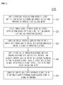
- the measuring step (S40) includes: a first step (S41) of supplying potential to the operation electrode and the flow sensing electrode; a second step (S42) of cutting off the supply of reference potential to the operation electrode for time of t1 from the time point when blood flows into the operation electrode; a third step (S43) of cutting off the supply of the reference potential to the flow sensing electrode at the time point when a blood speed is sensed at the flow sensing electrode; a fourth step (S44) of supplying the reference potential to the operation electrode after the second step; a fifth step (S45) of supplying the reference potential to the flow sensing electrode after a current value generated at the operation electrode is measured; and a sixth step (S46) of measuring the current value generated at the operation electrode after the fifth step.
- Fig. 5 is a graph illustrating potential variation of the flow sensing electrode and the operation electrode at the time of normal measurement (using a normal strip sensor and a normal strip connector).
- Fig. 6 is a graph illustrating potential variation of the flow sensing electrode and the operation electrode at the time of abnormal measurement (using a defect strip sensor or a defect strip connector).
- Fig. 5 and Fig. 6 are materials for confirming data when a potential application time to the flow sensing electrode is increased to t0 seconds to compare data for normal measurement and data for abnormal measurement.
- an output of the operation electrode is not affected by potential applied to the flow sensing electrode, but when the defect strip or the defect connector is used, a phenomenon that the output of the operation electrode has a lower potential than applied potential when the potential is applied to the flow sensing electrode.
- Table 1 shows steps performed according to external variation (supplying potential and cutting off supply of potential) and time variation at the operation electrode and the flow sensing electrode to test sensing the abnormal measurement of the personal blood glucose meter.
- the measurement value of the time t2 is displayed as a blood glucose value, and breakdown of the auxiliary electrode or a case where blood clots at the connector and the auxiliary electrode does not play the role is processed as an error using the measurement value at the time t3.
- the measurement value of the time t2 is displayed as a blood glucose value, and breakdown of the auxiliary electrode or a case where blood clots at the connector and the auxiliary electrode does not play the role is processed as an error using the measurement value at the time t3.
- the flow sensing electrode 21 is recognized as the auxiliary electrode 22 due to various problems, the potential of the auxiliary electrode 22 is changed and the blood glucose value is measured again in a short time after completing measurement of blood glucose to determine the recognition.
- a facing-type strip in which the operation electrode 23 and the flow sensing electrode 21 are positioned on a lower plate and the auxiliary electrode is positioned on an upper plate facing the lower plate, was used (see Fig. 2 ).
- the flow sensing electrode 21 replaces the auxiliary electrode 22.
- the facing-type strip takes a form of a plane-type strip, in which the operation electrode 23 and the auxiliary electrode 22 are position on the same plate, and thus the abnormal measurement occurs.
- the flow sensing electrode plays the role of the auxiliary electrode 22 by raising the potential of the flow sensing electrode 21 to the same potential as that of the operation electrode 23 after the first measurement, the potential difference from the operation electrode 23 disappears, and thus current is not generated.
- the first measurement current value is calculated as a blood glucose measurement value and the second measurement current value is not generated or becomes a negative value, it may be determined as a strip defect or a connector defect.
Landscapes
- Health & Medical Sciences (AREA)
- Life Sciences & Earth Sciences (AREA)
- Chemical & Material Sciences (AREA)
- Hematology (AREA)
- Molecular Biology (AREA)
- Immunology (AREA)
- Physics & Mathematics (AREA)
- Pathology (AREA)
- Analytical Chemistry (AREA)
- Biochemistry (AREA)
- General Health & Medical Sciences (AREA)
- General Physics & Mathematics (AREA)
- Electrochemistry (AREA)
- Chemical Kinetics & Catalysis (AREA)
- Engineering & Computer Science (AREA)
- Biomedical Technology (AREA)
- Urology & Nephrology (AREA)
- Medicinal Chemistry (AREA)
- Food Science & Technology (AREA)
- Ecology (AREA)
- Diabetes (AREA)
- Biotechnology (AREA)
- Cell Biology (AREA)
- Microbiology (AREA)
- Biophysics (AREA)
- Investigating Or Analysing Biological Materials (AREA)
Abstract
Description
- The present disclosure relates to a method for sensing whether blood glucose is normal or abnormal by self-monitoring, and more particularly, to a personal blood glucose meter capable of sensing abnormal measurement by controlling electric potential applied to an operation electrode and a flow sensing electrode and to a method for sensing abnormal measurement using the same.
- Recently, for diagnosing and preventing diabetes, the necessity to periodically measure the amount of glucose in blood (blood glucose) has been increased. Such blood glucose may be easily measured by using a hand-carried potable measuring instrument, and specifically, may be easily measured by using a biosensor in a strip form personally. An operation principle of the biosensor for measuring blood glucose is based on a colorimetric method or an electrochemical method.
- Among the methods, the electrochemical method is described by the following Reaction Formula 1, and the most significant feature thereof is to use an electron transfer mediator. The electron transfer mediator includes: ferrocene, ferrocene derivatives; quinines, quinone derivatives; organic and inorganic substance containing transition metal (such as hexa-amine ruthenium, a polymer containing osmium, potassium ferricyanide, etc.); and an electron transfer organic substance such as an organic conducting salt and violegen.
Reaction Formula 1
(1) glucose + GOx-FAD → gluconic acid + GOx-FADH2
(2) GOx-FADH2 + electron transfer mediator (oxidized state) → GOx-FAD + electron transfer mediator (reduced state)
(in the Formula, GOx represents glucose oxidase, and GOx-FAD and GOx-FADH2 respectively represent the oxidized state and the reduced state of FAD (flavin adenine dinucleotide) that is an active site of the glucose oxidase) - As shown in Reaction Formula 1, (1) firstly, glucose in blood is oxidized into gluconic acid by catalysis of glucose oxidase. FAD, which is the active site of the glucose oxidase, is reduced to FADH2. (2) Thereafter, the reduced FADH2 is oxidized into FAD through oxidation-reduction reaction with an electron transfer mediator, and the electron transfer mediator is reduced. The formed electron transfer mediator in a reduced state is diffused to an electrode surface. Hereat, concentration of blood glucose is measured by measuring current generated by applying oxidation potential of the electronic transfer mediator in a reduced state at an operation electrode surface.
- A biosensor based on the electrochemical method described above as an operation principle is referred to as an electrochemical biosensor. Unlike related art biosensors using the colorimetric method, such an electrochemical biosensor has an advantage that it is possible to use a sample without an additional pretreatment although the sample is turbid.
- Such an electrochemical biosensor is generally and conveniently used to monitor and control an amount of blood glucose, but accuracy of the sensor is greatly affected by various interference substances such as ascorbic acid, acetaminophen, and uric acid which are present in a blood sample and are easily oxidized.
- In addition, another serious error is caused by hematocrit (a degree of a ratio of hematocrit in blood). In people who regularly measure his blood glucose levels using a disposable biosensor strip, the biosensor greatly affected by a hematocrit level causes erroneous determination in the measurement result. As a result, even a risk to life of people using the biosensor may be caused.
- In the related art, several methods have been proposed as a method for decreasing an influence of hematocrit in a biosensor, for example, a method of additionally separating red blood cells; a method of applying a layer for removing red blood cells onto a reagent layer (
JP 1134461 JP 2000338076 US 5658444 ); a method of using a sensing film including a silica filler which is screen-printable and has an integrated reagent/blood cell separation function (US 6241862 B1 ); and a correction method of mathematically processing (chemometric method) a result obtained by applying application potential twice (the double excitation potentials) (WO 01/57510 A2 - However, the methods described above may cause great loss of a reagent in an extra step or in printing the reagent layer, in the manufacturing process, and it is difficult to simply apply a reagent mixture onto an operation electrode.
- Obtaining a rapid response time accurately with a small amount of samples, when using a biosensor, maximized user's convenience and is thus a very important. Particularly, when using a small amount of samples of 1 µl or less, preferably samples of 0.5 µl or less, more preferably samples of 0.3 µl or less, it is possible to collect and measure blood at a substitute site such as a forearm, thereby minimizing pain of a patient from measuring blood glucose.
- The time to obtain a response for the measurement result is preferably within 10 seconds, more preferably within 5 seconds if possible, and further most preferably about a time t1 if possible, but it is almost impossible to achieve such an object with a currently known technique.
- A personal blood glucose meter in an electrochemical-measure manner has been developed and used to overcome such a problem, but such a personal blood glucose meter in an electrochemical-measure manner calculates a blood glucose value by measuring current generated by a potential difference between an operation electrode and an auxiliary electrode of a strip. However, recently, a third electrode or more electrodes (referred to as the third electrode as a common name) in addition to two electrodes is positioned on a strip to accurately measure a blood glucose value.
- However, in the strip having two or more electrodes, the auxiliary electrode may not play the role due to breakdown of the auxiliary electrode, defect of a strip connector, or blood clotting of the connector caused by user's carelessness. At this time, the third electrode plays a role of the auxiliary electrode to generate an undesired potential difference, or to cause a strip to be misidentified as a strip in which arrangement between the operation electrode and the auxiliary electrode is completely different. Accordingly, there is a problem that the personal blood glucose meter may inform a user of an inaccurate measured value.
- Embodiments of the present invention are directed to provide a personal blood glucose meter and a method for sensing abnormal measurement using the same, capable of solving such typical problems that a counter electrode may not work well due to breakdown of a counter electrode, defect of a strip connector, or blood clotting of a connector caused by user's carelessness in a strip having two or more electrodes in a personal blood glucose meter, in this case an auxiliary electrode plays a role of the counter electrode to generate an undesired potential difference or to cause a strip to be misidentified as a strip in which an operation electrode and a counter electrode are totally different in structure.
- According to an aspect of the present invention, there is provided a personal blood glucose meter according to an embodiment of the present invention includes: a sensor strip collecting and supplying blood, wherein the sensor strip includes a sample; an electrode unit including a plurality of electrodes receiving sample blood, in which the blood and the sample are mixed, from the sensor strip to generate current based on a potential difference; an MCU measuring a current value generated from the electrode unit to determine whether a blood glucose value of the blood is normal or abnormal; a potential supply unit supplying potential to the electrode unit; and a display unit displaying a result value output from the MCU.
- The electrode unit includes: a flow sensing electrode for receiving the sample blood to generate first potential; an auxiliary electrode having a ground function; and an operation electrode for receiving the sample blood to generate second potential.
- The MCU measures current values of the operation electrode and the flow sensing electrode of the electrode unit and compares the current value with a preset reference current value to determine whether the blood glucose value is normal or abnormal.
- The MCU further includes a determination unit comparing a current value based on the potential difference with the reference current value, and transmitting an error message to the display when the measured current value is lower than the reference current value.
- To solve the problem described above, the method for sensing abnormality of a personal blood glucose meter according to an embodiment of the present invention includes: supplying reference potential from a potential supply unit to an operation electrode and a flow sensing electrode provided in the personal blood glucose meter; injecting sample blood in which blood and a sample supplied from the sensor strip are mixed, to the operation electrode and the flow sensing electrode; cutting off the reference potential supplied from the potential supply unit through MCU when blood inflow to the operation electrode is sensed; supplying potential to the operation electrode to classify current values of the operation electrode and the flow sensing electrode according to time to measure the current values at MCU, after passing through a predetermined time point from the blood inflow time point; and comparing the current value with the reference current value to determine abnormality of the personal blood glucose meter.
- The measuring includes: a first step of supplying potential to the operation electrode and the flow sensing electrode; a second step of cutting off the supply of the reference potential to the operation electrode during a time t1 from the time point when the blood flows into the operation electrode; a third step of cutting off the supply of the reference potential to the flow sensing electrode at the time point when a blood speed is detected at the flow sensing electrode; a forth step of supplying the reference potential to the operation electrode after the second step; a fifth step of supplying the reference potential to the flow sensing electrode after measuring the current value generated in the operation electrode; and a sixth step of measuring the current value generated in the operation electrode after the fifth step.
- According to the present invention, it is possible to prevent claims from users beforehand wherein, the claims occur in the case when blood clots at a counter pin of a connector of a personal blood glucose meter due to user's carelessness. Also, counter breakdown or connector defect of a strip, and connector defect of a personal blood glucose meter are determined and displayed as an error, thereby preventing an erroneously measured value from being delivered to a user in advance. Therefore, the present invention has an effect of preventing a medical accident due to the erroneously measured value.
- The above and other objects, features and other advantages of the present invention will be more clearly understood from the following detailed description taken in conjunction with the accompanying drawings, in which:
-
Fig. 1 is a block diagram illustrating a personal blood glucose meter according to an embodiment of the present invention; -
Fig. 2 is an exemplary diagram illustrating a facing-type strip used in the present invention; -
Fig. 3 is a flowchart illustrating a method for sensing abnormality of the personal blood glucose meter of the present invention; -
Fig. 4 is a flowchart more specifically illustrating a measuring step illustrated inFig. 3 ; -
Fig. 5 is a graph illustrating potential variation of a flow sensing electrode and an operation electrode at the time of normal measurement (using a normal strip sensor and a normal strip connector); and -
Fig. 6 is a graph illustrating potential variation of a flow sensing electrode and an operation electrode at the time of abnormal measurement (using a defect strip sensor or a defect strip connector). - Specific structural or functional explanations for embodiments according to the inventive concept which are disclosed in this specification or application are merely provided for the purpose of illustrating the embodiments according to the inventive concept. Thus, the embodiments according to the inventive concept may be implemented in various forms and are not construed as being limited to the embodiments described in this specification or application.
- The embodiments according to this inventive concept may be variously modified and may have multiple forms. Thus, specific embodiments are illustrated in the drawings or described in detail in this specification or application. However, this is not intended to limit the embodiments according to the inventive concept as the specific disclosed forms; rather it should be understood that all of variations, equivalents or substitutes contained in the concept and technical scope of the present invention are also included.
- The terms 'first' and/or 'second' may be used to describe various elements, however, the elements should not be limited by these terms. These terms are merely used for the purpose of discriminating one element from another element, and, for example, the first element may be designated as the second element, and vice versa, without departing from the spirit or scope of the present invention.
- When one element is referred to as being 'connected' or "coupled' to another element, it should be understood that the former may be directly connected or coupled to the latter, but connected or coupled to the latter via an intervening element. On the contrary, when one element is referred to as being 'directly connected' or 'directly coupled' to another element, it should be understood that the former is connected to the latter without an intervening element therebetween. Other expressions for describing the positional relationship between elements, that is, "between", "directly between" or "adjacent to" or "directly adjacent to" should be interpreted in the same manner as above.
- Terms used herein are merely provided for illustration of specific embodiments, and not limited to the present invention. A singular form, otherwise indicated, include a plural form. Herein, the term "comprise" or "have" intends to mean that there may be specified features, numerals, steps, operations, elements, parts, or combinations thereof, not excluding the possibility of the presence or addition of the specified features, numerals, steps, operations, elements, parts, or combinations thereof.
- Otherwise indicated herein, all the terms used herein, which include technical or scientific terms, may have the same meaning that is generally understood by a person skilled in the art. In general, the terms defined in the dictionary should be considered to have the same meaning as the contextual meaning of the related art, and, unless clearly defined herein, should not be understood abnormally or excessively formal meaning.
- Hereinafter, specific embodiments of the present invention will be described in detail with reference to the accompanying drawings.
-
Fig. 1 is a block diagram illustrating a personal blood glucose meter according to an embodiment of the present invention, andFig. 2 is an exemplary diagram illustrating a facing-type strip used in the present invention. - As illustrated in
Fig. 1 , a personalblood glucose meter 100 of the present invention includes asensor strip 10, anelectrode unit 20, anMCU 30, apotential supply unit 40, and adisplayer 50. - The
sensor strip 10 collects and supplies blood of a user or the other person, and is provided with a sample therein. - More specifically, in the
sensor strip 10 of the present invention, a thin layer electrochemical cell is configured by separately forming: an operation electrode and an auxiliary electrode on two flat insulating plates in an electrode configuration; forming, a connection line connectable to the auxiliary electrode, on the plate on which the operation electrode is formed; printing a conductive material onto a part of the connection line to be thick by a laminated structure to form a portion which is 3-dimensionally connected to the auxiliary electrode; and separating the operation electrode and the auxiliary electrode formed on two flat insulating plates at a position symmetrically or asymmetrically facing each other by a pressure adhesive separation plate with a thickness of 50 to 250 µm (Reference to facing electrodes: E. K. Bauman et al., Analytical Chemistry, vol 37, p 1378, 1965; K. B. Oldham in "Microelectrodes: Theory and Applications," Kluwer Academic Publishers, 1991). - The thin layer separation plate is provided with a fine flow path through which a biological sample may be injected and retained in a measurement space formed by the operation electrode and the auxiliary electrode and of which a total volume is in unit of micro-liter. In formation of electrodes, the flow sensing electrode in the thin layer separation plate is apart from the operation electrode (or the auxiliary electrode) at a proper distance. Preferably, the flow sensing electrode is positioned at a distance where blood having the amount of hemocytes of 42% and treated with EDTA (ethylene diaminetetraacetic acid) reaches within about 600 ms along the fine flow path with a width of 0.5 to 2 mm and a height of 50 to 250 µm, more preferably is positioned at a distance where an EDTA-untreated sample reaches within 300 ms, and even more preferably is positioned at a distance where the sample reaches within 200 ms.
- The operation electrode (or the auxiliary electrode) and the flow sensing electrode formed on one substrate may form a biosensor characterized by having a configuration in which the operation electrode (or the auxiliary electrode) faces the auxiliary electrode (also used as the reference electrode) (or the operation electrode) (facing type).
- The
electrode unit 20 includes a plurality ofelectrodes sensor strip 10 to generate electric current based on a potential difference. - The
electrode unit 20 includes aflow sensing electrode 21 for receiving the sample blood to generate a first potential value, anauxiliary electrode 22 having a ground function, and anoperation electrode 23 for receiving the sample blood to generate a second potential value. - The
MCU 30 measures a current value generated from theelectrode unit 20 and calculates a blood glucose value. Also, theMCU 30 measures the current value again at a certain time interval, and compares the measured current value with a preset reference current value to determine whether the blood glucose is normal or abnormal. TheMCU 30 further includes adetermination unit 31 for comparing the current value based on the potential difference with the reference current value and transmitting an error message to the display when the measured current value is lower than the reference current value. -
Fig. 3 is a flowchart illustrating a method for sensing abnormality of a personal blood glucose meter of the present invention, andFig. 4 is a flowchart more specifically illustrating the measuring step illustrated inFig. 3 . - As illustrated in
Fig. 3 , the method for sensing abnormality (S100) of a personal blood glucose meter of the present invention includes a potential supplying step (S10), a blood injecting step (S20), a potential supply cutting-off step (S30), a measuring step (S40), and a determining step (S50). - The potential supplying step (S10) may be a step of supplying reference potential from the potential supply unit to the flow sensing electrode and the operation electrode provided in the personal blood glucose meter.
- The blood injecting step (S20) may be a step of injecting sample blood, in which blood and a sample supplied from a sensor strip are mixed, to the flow sensing electrode and the operation electrode.
- The potential supply cutting-off step (S30) may be a step of cutting off reference potential supplied from the potential supply unit through the MCU when blood inflow to the operation electrode is detected.
- The measuring step (S40) may be a step of supplying potential to the operation electrode and the flow sensing electrode with an interval of time, and classifying a current value of the operation electrode according to time to measure the current value at the MCU, after passing through a certain time point from the blood inflow time point.
- The determining step (S50) may be a step of comparing the current value with the reference current value to determine whether the personal blood glucose meter is normal or abnormal.
- More specifically, as illustrated in
Fig. 4 , the measuring step (S40) includes: a first step (S41) of supplying potential to the operation electrode and the flow sensing electrode; a second step (S42) of cutting off the supply of reference potential to the operation electrode for time of t1 from the time point when blood flows into the operation electrode; a third step (S43) of cutting off the supply of the reference potential to the flow sensing electrode at the time point when a blood speed is sensed at the flow sensing electrode; a fourth step (S44) of supplying the reference potential to the operation electrode after the second step; a fifth step (S45) of supplying the reference potential to the flow sensing electrode after a current value generated at the operation electrode is measured; and a sixth step (S46) of measuring the current value generated at the operation electrode after the fifth step. -
Fig. 5 is a graph illustrating potential variation of the flow sensing electrode and the operation electrode at the time of normal measurement (using a normal strip sensor and a normal strip connector).Fig. 6 is a graph illustrating potential variation of the flow sensing electrode and the operation electrode at the time of abnormal measurement (using a defect strip sensor or a defect strip connector). -
Fig. 5 and Fig. 6 are materials for confirming data when a potential application time to the flow sensing electrode is increased to t0 seconds to compare data for normal measurement and data for abnormal measurement. When the normal strip and the normal connector are used, an output of the operation electrode is not affected by potential applied to the flow sensing electrode, but when the defect strip or the defect connector is used, a phenomenon that the output of the operation electrode has a lower potential than applied potential when the potential is applied to the flow sensing electrode.[Table 1] time variation operation electrode flow sensing electrode before measurement start supplying potential supplying potential after measurement start cutting off supply of potential before starting measurement cutting off supply of reference potential after measuring a blood speed time t1 (time 0 to time t1) after measurement start cutting off supply of potential cutting off supply of potential time t2 (time t1 to time t2) after measurement start supplying potential cutting off supply of potential measure, time t2 measuring current, calculating as blood glucose value supplying potential to flow detection electrode after measuring current at operation electrode time t2 to time t3 after measure supplying potential supplying potential measure, time t3 measuring electric current, determining whether normal measurement or not supplying potential after measure cutting off supply of potential cutting off supply of potential - Table 1 shows steps performed according to external variation (supplying potential and cutting off supply of potential) and time variation at the operation electrode and the flow sensing electrode to test sensing the abnormal measurement of the personal blood glucose meter.
- Referring to
Fig. 5, Fig. 6 , and Table 1, in a case of the normal strip, there is no significant difference between the blood glucose value measured at the time t2 and the value measured again at the time t3 after raising low voltage of the auxiliary electrode for a certain time, but in the case of the breakdown strip, there is a significant difference between the value measured at the time t2 and the normal value, and the current value measured at the time t3 has a negative value. - The reason for this result is that because the flow sensing electrode plays a role of the auxiliary electrode when the auxiliary electrode does not play it's own role due to the reason described above, the potential difference between the operation electrode and the flow sensing electrode disappears when the potential of the flow sensing electrode is raised to the reference potential after the time t2, and therefore an effect that the potential difference of the operation electrode with respect to the auxiliary electrode disappears occurs.
- Accordingly, the measurement value of the time t2 is displayed as a blood glucose value, and breakdown of the auxiliary electrode or a case where blood clots at the connector and the auxiliary electrode does not play the role is processed as an error using the measurement value at the time t3. Thus, it is possible to prevent an erroneous measurement value from being transferred to a user.
- Therefore, in the present invention, when the
flow sensing electrode 21 is recognized as theauxiliary electrode 22 due to various problems, the potential of theauxiliary electrode 22 is changed and the blood glucose value is measured again in a short time after completing measurement of blood glucose to determine the recognition. - When the normal strip and the normal connector are used, there is little difference between a first measured blood glucose value and a value re-measured a short time after. However, when the broken strip or the broken connector is used, the flow sensing electrode is used as the auxiliary electrode, and thereby, the potential of the auxiliary electrode is different from that of the normal strip. As a result, there is a significant difference between the first measurement value and the re-measurement value.
- In order to prove this, a facing-type strip, in which the
operation electrode 23 and theflow sensing electrode 21 are positioned on a lower plate and the auxiliary electrode is positioned on an upper plate facing the lower plate, was used (seeFig. 2 ). - When an abnormal situation such as breakdown of the auxiliary electrode occurs, the
flow sensing electrode 21 replaces theauxiliary electrode 22. Also, the facing-type strip takes a form of a plane-type strip, in which theoperation electrode 23 and theauxiliary electrode 22 are position on the same plate, and thus the abnormal measurement occurs. - Although the flow sensing electrode plays the role of the
auxiliary electrode 22 by raising the potential of theflow sensing electrode 21 to the same potential as that of theoperation electrode 23 after the first measurement, the potential difference from theoperation electrode 23 disappears, and thus current is not generated. - Accordingly, when the first measurement current value is calculated as a blood glucose measurement value and the second measurement current value is not generated or becomes a negative value, it may be determined as a strip defect or a connector defect.
- According to the present invention, it is possible to previously prevent claims from users generated when blood clots at the auxiliary electrode pin of a connector of a personal blood glucose meter due to user's carelessness. Also, counter breakdown or a connector defect of a strip, and a connector defect of a personal blood glucose meter are displayed by an error message, thereby preventing an erroneous measurement value from being transferred to a user and preventing a medical accident.
- The embodiments of the present invention disclosed in the specification and the drawings are to merely present specific examples to easily explain the technical contents of the present invention and to help the present invention to be understood, and do not limit the scope of the present invention. Even in addition to the embodiments disclosed herein, it is obvious that other modified examples based on the technical idea of the present invention can be embodied by a person skilled in the art to which the present invention pertains.
Claims (6)
- A personal blood glucose meter comprising:a sensor strip for collecting and supplying blood, wherein the sensor strip includes a sample;an electrode unit including a plurality of electrodes for receiving sample blood, in which the blood and the sample are mixed, from the sensor strip to generate electric current based on a potential difference;an MCU for measuring a current value generated from the electrode unit to determine whether a blood glucose value of the blood is normal or abnormal;a potential supply unit for supplying potential to the electrode unit; anda display unit for displaying a result value output from the MCU.
- The personal blood glucose meter as set forth in claim 1, wherein the electrode unit includes:a flow sensing electrode for receiving the sample blood to generate first potential;an auxiliary electrode having a ground function; andan operation electrode for receiving the sample blood to generate second potential.
- The personal blood glucose meter as set forth in claim 1, wherein the MCU changes the potential of the plurality of electrodes of the electrode unit to measure the current value of the operation electrode at least twice, and compares the current value with a preset reference current value to determine whether the blood glucose value is normal or abnormal.
- The personal blood glucose meter as set forth in claim 3, wherein the MCU further comprises a determination unit for comparing a current value based on the potential difference with the reference current value, and transmitting an error message to the display when the measured current value is lower than the reference current value.
- A method for sensing abnormality of a personal blood glucose meter, the method comprising:supplying reference potential from a potential supply unit to a flow sensing electrode and an operation electrode provided in the personal blood glucose meter;injecting sample blood, in which blood and a sample supplied from a sensor strip are mixed, to the flow sensing electrode and the operation electrode;cutting off the reference potential supplied from the potential supply unit through an MCU when blood inflow at the operation electrode is sensed;supplying potential to the operation electrode and the flow sensing electrode with time interval, and classifying a current value of the operation electrode according to time to measure the current value at the MCU, after passing through a certain time point from the blood inflow time point; andcomparing the current value with the reference current value to determine whether the personal blood glucose meter is normal or abnormal.
- The method for sensing abnormality of the personal blood glucose meter as set forth in claim 5, wherein the measuring comprises:a first step of supplying potential to the operation electrode and the flow sensing electrode;a second step of cutting off the supply of the reference potential to the operation electrode during a time t1 from the time point when the blood flows into the operation electrode;a third step of cutting off the supply of the reference potential to the flow sensing electrode at the time point when a blood speed is sensed at the flow sensing electrode;a fourth of supplying the reference potential to the operation electrode after the second step;a fifth step of supplying the reference potential to the flow sensing electrode after measuring the current value generated in the operation electrode; anda sixth step of measuring the current value generated in the operation electrode after the fifth step.
Applications Claiming Priority (2)
| Application Number | Priority Date | Filing Date | Title |
|---|---|---|---|
| KR20110117618A KR101367262B1 (en) | 2011-11-11 | 2011-11-11 | Blood Glucose Sensor and sensing error detecting method using thereof |
| PCT/KR2012/008174 WO2013069895A1 (en) | 2011-11-11 | 2012-10-09 | Personal blood glucose meter and abnormal measurement detection method using same |
Publications (3)
| Publication Number | Publication Date |
|---|---|
| EP2778683A1 true EP2778683A1 (en) | 2014-09-17 |
| EP2778683A4 EP2778683A4 (en) | 2014-09-24 |
| EP2778683B1 EP2778683B1 (en) | 2016-11-30 |
Family
ID=48290222
Family Applications (1)
| Application Number | Title | Priority Date | Filing Date |
|---|---|---|---|
| EP12847781.7A Active EP2778683B1 (en) | 2011-11-11 | 2012-10-09 | Method of detecting an abnormal measurement with a personal blood glucose meter |
Country Status (5)
| Country | Link |
|---|---|
| US (1) | US10024816B2 (en) |
| EP (1) | EP2778683B1 (en) |
| KR (1) | KR101367262B1 (en) |
| CN (1) | CN104024857B (en) |
| WO (1) | WO2013069895A1 (en) |
Families Citing this family (7)
| Publication number | Priority date | Publication date | Assignee | Title |
|---|---|---|---|---|
| CN104983430B (en) * | 2015-07-22 | 2018-10-02 | 通普生物科技(北京)有限公司 | The blood-sugar detecting instrument of non-intrusion type |
| CN105787288A (en) * | 2016-05-11 | 2016-07-20 | 鼎泰生物科技(海南)有限公司 | Method and device for executing failure warning on glucometer by virtue of social application |
| KR101868015B1 (en) * | 2016-05-17 | 2018-06-15 | 주식회사 아이센스 | Device of Auto-Supplying Insulin and Diabetic Management System Using the Same |
| KR101915728B1 (en) | 2016-10-24 | 2018-11-07 | (주)오상헬스케어 | Self diagnosis apparatus for health tester and method thereof |
| US11660053B2 (en) | 2018-04-16 | 2023-05-30 | Samsung Electronics Co., Ltd. | Apparatus and method for monitoring bio-signal measuring condition, and apparatus and method for measuring bio-information |
| CN111329490B (en) * | 2018-12-18 | 2024-09-13 | 林创华 | A non-invasive anti-interference blood sugar detector and a method for detecting blood sugar |
| CN120690429A (en) * | 2024-03-22 | 2025-09-23 | 华为技术有限公司 | Method and electronic device for identifying abnormal blood sugar events |
Family Cites Families (18)
| Publication number | Priority date | Publication date | Assignee | Title |
|---|---|---|---|---|
| JPH01134461A (en) | 1987-11-20 | 1989-05-26 | Matsushita Electric Ind Co Ltd | Electrophotographic sensitive body and manufacture of same |
| GB9309797D0 (en) | 1993-05-12 | 1993-06-23 | Medisense Inc | Electrochemical sensors |
| US6241862B1 (en) | 1996-02-14 | 2001-06-05 | Inverness Medical Technology, Inc. | Disposable test strips with integrated reagent/blood separation layer |
| US6475372B1 (en) | 2000-02-02 | 2002-11-05 | Lifescan, Inc. | Electrochemical methods and devices for use in the determination of hematocrit corrected analyte concentrations |
| JP2000338076A (en) | 1999-05-25 | 2000-12-08 | Matsushita Electric Ind Co Ltd | Biosensor |
| US6733655B1 (en) * | 2000-03-08 | 2004-05-11 | Oliver W. H. Davies | Measurement of substances in liquids |
| ES2609053T3 (en) * | 2000-03-08 | 2017-04-18 | Lifescan Scotland Limited | Measurement of substances in liquids |
| AU784254B2 (en) * | 2001-05-21 | 2006-03-02 | Bayer Corporation | Improved electrochemical sensor |
| US6872298B2 (en) * | 2001-11-20 | 2005-03-29 | Lifescan, Inc. | Determination of sample volume adequacy in biosensor devices |
| US7220573B2 (en) | 2002-06-21 | 2007-05-22 | Agilent Technologies, Inc. | Array assay devices and methods of using the same |
| US7132041B2 (en) | 2003-02-11 | 2006-11-07 | Bayer Healthcare Llc | Methods of determining the concentration of an analyte in a fluid test sample |
| KR100698961B1 (en) * | 2005-02-04 | 2007-03-26 | 주식회사 아이센스 | Electrochemical Biosensor |
| EP2053389A4 (en) | 2006-07-26 | 2013-12-25 | Panasonic Corp | MEASURING SYSTEM WITH BIOSENSOR AND METHOD FOR DETECTING ABNORMAL WAVE SHAPES IN THE BIOSENSOR |
| CA2658919C (en) * | 2006-07-26 | 2018-01-02 | Panasonic Corporation | Biosensor measurement system and measurement method |
| KR100799354B1 (en) | 2007-11-08 | 2008-01-30 | 주식회사 인포피아 | Reagent Container |
| US8603768B2 (en) * | 2008-01-17 | 2013-12-10 | Lifescan, Inc. | System and method for measuring an analyte in a sample |
| KR101058754B1 (en) * | 2009-09-22 | 2011-08-24 | 주식회사 인포피아 | Biological Sample Quantitative Measurement Method and Biological Sample Quantitative Measurement System |
| IL209760A (en) * | 2009-12-11 | 2015-05-31 | Lifescan Scotland Ltd | Fill sufficiency method and system |
-
2011
- 2011-11-11 KR KR20110117618A patent/KR101367262B1/en active Active
-
2012
- 2012-10-09 US US14/357,177 patent/US10024816B2/en active Active
- 2012-10-09 EP EP12847781.7A patent/EP2778683B1/en active Active
- 2012-10-09 CN CN201280064769.9A patent/CN104024857B/en not_active Expired - Fee Related
- 2012-10-09 WO PCT/KR2012/008174 patent/WO2013069895A1/en not_active Ceased
Also Published As
| Publication number | Publication date |
|---|---|
| WO2013069895A1 (en) | 2013-05-16 |
| US10024816B2 (en) | 2018-07-17 |
| CN104024857A (en) | 2014-09-03 |
| KR101367262B1 (en) | 2014-02-26 |
| EP2778683A4 (en) | 2014-09-24 |
| US20140299487A1 (en) | 2014-10-09 |
| EP2778683B1 (en) | 2016-11-30 |
| CN104024857B (en) | 2016-04-06 |
| KR20130052266A (en) | 2013-05-22 |
Similar Documents
| Publication | Publication Date | Title |
|---|---|---|
| EP2871470B1 (en) | Electrochemical biosensor with improved accuracy | |
| JP5820014B2 (en) | System, apparatus and method for improving biosensor accuracy using fill time | |
| EP2778683B1 (en) | Method of detecting an abnormal measurement with a personal blood glucose meter | |
| EP2553441B1 (en) | Electrochemical analyte measurement method and system | |
| US8083925B2 (en) | Analyte determination methods and devices | |
| EP2473847B1 (en) | Glucose measurement method and system | |
| KR100698961B1 (en) | Electrochemical Biosensor | |
| US20070235346A1 (en) | System and methods for providing corrected analyte concentration measurements | |
| US10620148B2 (en) | Method and test element for electrochemically detecting at least one analyte in a sample of a body fluid | |
| EP3560423A1 (en) | Analyte measurement method with hematocrit compensation | |
| KR20120099452A (en) | Underfill recognition system for a biosensor | |
| RU2670215C1 (en) | Precise measurements of the analyte using the electrochemical test-strip for the determination of the time of the analyte measuring on the basis of the measured temperature, physical characteristics and estimation concentration of the analyte and their temperature-compensated values | |
| HK1179345B (en) | Electrochemical analyte measurement method and system | |
| HK1179345A (en) | Electrochemical analyte measurement method and system | |
| HK1181851B (en) | Electrochemical analyte measurement system and method | |
| HK40013207A (en) | Analyte measurement method with hematocrit compensation | |
| HK1172085B (en) | Glucose measurement method and system | |
| HK1188827B (en) | Method for determining a hematocrit-corrected test current in glucose measurements | |
| HK1188827A (en) | Method for determining a hematocrit-corrected test current in glucose measurements | |
| HK1181851A (en) | Electrochemical analyte measurement method and system | |
| HK1181852A (en) | Electrochemical analyte measurement method and system | |
| HK1180763A (en) | Electrochemical analyte measurement method and system |
Legal Events
| Date | Code | Title | Description |
|---|---|---|---|
| PUAI | Public reference made under article 153(3) epc to a published international application that has entered the european phase |
Free format text: ORIGINAL CODE: 0009012 |
|
| 17P | Request for examination filed |
Effective date: 20140509 |
|
| AK | Designated contracting states |
Kind code of ref document: A1 Designated state(s): AL AT BE BG CH CY CZ DE DK EE ES FI FR GB GR HR HU IE IS IT LI LT LU LV MC MK MT NL NO PL PT RO RS SE SI SK SM TR |
|
| A4 | Supplementary search report drawn up and despatched |
Effective date: 20140826 |
|
| RIC1 | Information provided on ipc code assigned before grant |
Ipc: G01N 27/327 20060101ALI20140820BHEP Ipc: G01N 33/66 20060101AFI20140820BHEP Ipc: G01N 33/49 20060101ALI20140820BHEP |
|
| DAX | Request for extension of the european patent (deleted) | ||
| 17Q | First examination report despatched |
Effective date: 20150728 |
|
| GRAP | Despatch of communication of intention to grant a patent |
Free format text: ORIGINAL CODE: EPIDOSNIGR1 |
|
| INTG | Intention to grant announced |
Effective date: 20160616 |
|
| GRAS | Grant fee paid |
Free format text: ORIGINAL CODE: EPIDOSNIGR3 |
|
| GRAA | (expected) grant |
Free format text: ORIGINAL CODE: 0009210 |
|
| AK | Designated contracting states |
Kind code of ref document: B1 Designated state(s): AL AT BE BG CH CY CZ DE DK EE ES FI FR GB GR HR HU IE IS IT LI LT LU LV MC MK MT NL NO PL PT RO RS SE SI SK SM TR |
|
| REG | Reference to a national code |
Ref country code: CH Ref legal event code: EP Ref country code: GB Ref legal event code: FG4D |
|
| REG | Reference to a national code |
Ref country code: AT Ref legal event code: REF Ref document number: 850290 Country of ref document: AT Kind code of ref document: T Effective date: 20161215 |
|
| REG | Reference to a national code |
Ref country code: IE Ref legal event code: FG4D |
|
| REG | Reference to a national code |
Ref country code: DE Ref legal event code: R096 Ref document number: 602012026177 Country of ref document: DE |
|
| PG25 | Lapsed in a contracting state [announced via postgrant information from national office to epo] |
Ref country code: LV Free format text: LAPSE BECAUSE OF FAILURE TO SUBMIT A TRANSLATION OF THE DESCRIPTION OR TO PAY THE FEE WITHIN THE PRESCRIBED TIME-LIMIT Effective date: 20161130 |
|
| REG | Reference to a national code |
Ref country code: LT Ref legal event code: MG4D |
|
| REG | Reference to a national code |
Ref country code: NL Ref legal event code: MP Effective date: 20161130 |
|
| REG | Reference to a national code |
Ref country code: AT Ref legal event code: MK05 Ref document number: 850290 Country of ref document: AT Kind code of ref document: T Effective date: 20161130 |
|
| PG25 | Lapsed in a contracting state [announced via postgrant information from national office to epo] |
Ref country code: SE Free format text: LAPSE BECAUSE OF FAILURE TO SUBMIT A TRANSLATION OF THE DESCRIPTION OR TO PAY THE FEE WITHIN THE PRESCRIBED TIME-LIMIT Effective date: 20161130 Ref country code: NO Free format text: LAPSE BECAUSE OF FAILURE TO SUBMIT A TRANSLATION OF THE DESCRIPTION OR TO PAY THE FEE WITHIN THE PRESCRIBED TIME-LIMIT Effective date: 20170228 Ref country code: GR Free format text: LAPSE BECAUSE OF FAILURE TO SUBMIT A TRANSLATION OF THE DESCRIPTION OR TO PAY THE FEE WITHIN THE PRESCRIBED TIME-LIMIT Effective date: 20170301 Ref country code: LT Free format text: LAPSE BECAUSE OF FAILURE TO SUBMIT A TRANSLATION OF THE DESCRIPTION OR TO PAY THE FEE WITHIN THE PRESCRIBED TIME-LIMIT Effective date: 20161130 |
|
| PG25 | Lapsed in a contracting state [announced via postgrant information from national office to epo] |
Ref country code: AT Free format text: LAPSE BECAUSE OF FAILURE TO SUBMIT A TRANSLATION OF THE DESCRIPTION OR TO PAY THE FEE WITHIN THE PRESCRIBED TIME-LIMIT Effective date: 20161130 Ref country code: RS Free format text: LAPSE BECAUSE OF FAILURE TO SUBMIT A TRANSLATION OF THE DESCRIPTION OR TO PAY THE FEE WITHIN THE PRESCRIBED TIME-LIMIT Effective date: 20161130 Ref country code: HR Free format text: LAPSE BECAUSE OF FAILURE TO SUBMIT A TRANSLATION OF THE DESCRIPTION OR TO PAY THE FEE WITHIN THE PRESCRIBED TIME-LIMIT Effective date: 20161130 Ref country code: PL Free format text: LAPSE BECAUSE OF FAILURE TO SUBMIT A TRANSLATION OF THE DESCRIPTION OR TO PAY THE FEE WITHIN THE PRESCRIBED TIME-LIMIT Effective date: 20161130 Ref country code: ES Free format text: LAPSE BECAUSE OF FAILURE TO SUBMIT A TRANSLATION OF THE DESCRIPTION OR TO PAY THE FEE WITHIN THE PRESCRIBED TIME-LIMIT Effective date: 20161130 Ref country code: PT Free format text: LAPSE BECAUSE OF FAILURE TO SUBMIT A TRANSLATION OF THE DESCRIPTION OR TO PAY THE FEE WITHIN THE PRESCRIBED TIME-LIMIT Effective date: 20170330 Ref country code: FI Free format text: LAPSE BECAUSE OF FAILURE TO SUBMIT A TRANSLATION OF THE DESCRIPTION OR TO PAY THE FEE WITHIN THE PRESCRIBED TIME-LIMIT Effective date: 20161130 |
|
| PG25 | Lapsed in a contracting state [announced via postgrant information from national office to epo] |
Ref country code: NL Free format text: LAPSE BECAUSE OF FAILURE TO SUBMIT A TRANSLATION OF THE DESCRIPTION OR TO PAY THE FEE WITHIN THE PRESCRIBED TIME-LIMIT Effective date: 20161130 |
|
| PG25 | Lapsed in a contracting state [announced via postgrant information from national office to epo] |
Ref country code: EE Free format text: LAPSE BECAUSE OF FAILURE TO SUBMIT A TRANSLATION OF THE DESCRIPTION OR TO PAY THE FEE WITHIN THE PRESCRIBED TIME-LIMIT Effective date: 20161130 Ref country code: SK Free format text: LAPSE BECAUSE OF FAILURE TO SUBMIT A TRANSLATION OF THE DESCRIPTION OR TO PAY THE FEE WITHIN THE PRESCRIBED TIME-LIMIT Effective date: 20161130 Ref country code: CZ Free format text: LAPSE BECAUSE OF FAILURE TO SUBMIT A TRANSLATION OF THE DESCRIPTION OR TO PAY THE FEE WITHIN THE PRESCRIBED TIME-LIMIT Effective date: 20161130 Ref country code: DK Free format text: LAPSE BECAUSE OF FAILURE TO SUBMIT A TRANSLATION OF THE DESCRIPTION OR TO PAY THE FEE WITHIN THE PRESCRIBED TIME-LIMIT Effective date: 20161130 Ref country code: RO Free format text: LAPSE BECAUSE OF FAILURE TO SUBMIT A TRANSLATION OF THE DESCRIPTION OR TO PAY THE FEE WITHIN THE PRESCRIBED TIME-LIMIT Effective date: 20161130 |
|
| PG25 | Lapsed in a contracting state [announced via postgrant information from national office to epo] |
Ref country code: BE Free format text: LAPSE BECAUSE OF FAILURE TO SUBMIT A TRANSLATION OF THE DESCRIPTION OR TO PAY THE FEE WITHIN THE PRESCRIBED TIME-LIMIT Effective date: 20161130 Ref country code: BG Free format text: LAPSE BECAUSE OF FAILURE TO SUBMIT A TRANSLATION OF THE DESCRIPTION OR TO PAY THE FEE WITHIN THE PRESCRIBED TIME-LIMIT Effective date: 20170228 Ref country code: SM Free format text: LAPSE BECAUSE OF FAILURE TO SUBMIT A TRANSLATION OF THE DESCRIPTION OR TO PAY THE FEE WITHIN THE PRESCRIBED TIME-LIMIT Effective date: 20161130 Ref country code: IT Free format text: LAPSE BECAUSE OF FAILURE TO SUBMIT A TRANSLATION OF THE DESCRIPTION OR TO PAY THE FEE WITHIN THE PRESCRIBED TIME-LIMIT Effective date: 20161130 |
|
| REG | Reference to a national code |
Ref country code: DE Ref legal event code: R097 Ref document number: 602012026177 Country of ref document: DE |
|
| PLBE | No opposition filed within time limit |
Free format text: ORIGINAL CODE: 0009261 |
|
| STAA | Information on the status of an ep patent application or granted ep patent |
Free format text: STATUS: NO OPPOSITION FILED WITHIN TIME LIMIT |
|
| 26N | No opposition filed |
Effective date: 20170831 |
|
| PG25 | Lapsed in a contracting state [announced via postgrant information from national office to epo] |
Ref country code: SI Free format text: LAPSE BECAUSE OF FAILURE TO SUBMIT A TRANSLATION OF THE DESCRIPTION OR TO PAY THE FEE WITHIN THE PRESCRIBED TIME-LIMIT Effective date: 20161130 |
|
| PG25 | Lapsed in a contracting state [announced via postgrant information from national office to epo] |
Ref country code: MC Free format text: LAPSE BECAUSE OF FAILURE TO SUBMIT A TRANSLATION OF THE DESCRIPTION OR TO PAY THE FEE WITHIN THE PRESCRIBED TIME-LIMIT Effective date: 20161130 |
|
| REG | Reference to a national code |
Ref country code: CH Ref legal event code: PL |
|
| REG | Reference to a national code |
Ref country code: IE Ref legal event code: MM4A |
|
| REG | Reference to a national code |
Ref country code: FR Ref legal event code: ST Effective date: 20180629 |
|
| PG25 | Lapsed in a contracting state [announced via postgrant information from national office to epo] |
Ref country code: LU Free format text: LAPSE BECAUSE OF NON-PAYMENT OF DUE FEES Effective date: 20171009 Ref country code: LI Free format text: LAPSE BECAUSE OF NON-PAYMENT OF DUE FEES Effective date: 20171031 Ref country code: CH Free format text: LAPSE BECAUSE OF NON-PAYMENT OF DUE FEES Effective date: 20171031 |
|
| PG25 | Lapsed in a contracting state [announced via postgrant information from national office to epo] |
Ref country code: FR Free format text: LAPSE BECAUSE OF NON-PAYMENT OF DUE FEES Effective date: 20171031 |
|
| PG25 | Lapsed in a contracting state [announced via postgrant information from national office to epo] |
Ref country code: MT Free format text: LAPSE BECAUSE OF NON-PAYMENT OF DUE FEES Effective date: 20171009 |
|
| PG25 | Lapsed in a contracting state [announced via postgrant information from national office to epo] |
Ref country code: IE Free format text: LAPSE BECAUSE OF NON-PAYMENT OF DUE FEES Effective date: 20171009 |
|
| PG25 | Lapsed in a contracting state [announced via postgrant information from national office to epo] |
Ref country code: HU Free format text: LAPSE BECAUSE OF FAILURE TO SUBMIT A TRANSLATION OF THE DESCRIPTION OR TO PAY THE FEE WITHIN THE PRESCRIBED TIME-LIMIT; INVALID AB INITIO Effective date: 20121009 |
|
| PG25 | Lapsed in a contracting state [announced via postgrant information from national office to epo] |
Ref country code: CY Free format text: LAPSE BECAUSE OF NON-PAYMENT OF DUE FEES Effective date: 20161130 |
|
| PG25 | Lapsed in a contracting state [announced via postgrant information from national office to epo] |
Ref country code: MK Free format text: LAPSE BECAUSE OF FAILURE TO SUBMIT A TRANSLATION OF THE DESCRIPTION OR TO PAY THE FEE WITHIN THE PRESCRIBED TIME-LIMIT Effective date: 20161130 |
|
| PG25 | Lapsed in a contracting state [announced via postgrant information from national office to epo] |
Ref country code: TR Free format text: LAPSE BECAUSE OF FAILURE TO SUBMIT A TRANSLATION OF THE DESCRIPTION OR TO PAY THE FEE WITHIN THE PRESCRIBED TIME-LIMIT Effective date: 20161130 |
|
| PG25 | Lapsed in a contracting state [announced via postgrant information from national office to epo] |
Ref country code: AL Free format text: LAPSE BECAUSE OF FAILURE TO SUBMIT A TRANSLATION OF THE DESCRIPTION OR TO PAY THE FEE WITHIN THE PRESCRIBED TIME-LIMIT Effective date: 20161130 Ref country code: IS Free format text: LAPSE BECAUSE OF FAILURE TO SUBMIT A TRANSLATION OF THE DESCRIPTION OR TO PAY THE FEE WITHIN THE PRESCRIBED TIME-LIMIT Effective date: 20170330 |
|
| PGFP | Annual fee paid to national office [announced via postgrant information from national office to epo] |
Ref country code: GB Payment date: 20250904 Year of fee payment: 14 |
|
| PGFP | Annual fee paid to national office [announced via postgrant information from national office to epo] |
Ref country code: DE Payment date: 20250902 Year of fee payment: 14 |