EP2778621A2 - Magnetic Angle Position Sensor - Google Patents
Magnetic Angle Position Sensor Download PDFInfo
- Publication number
- EP2778621A2 EP2778621A2 EP14158442.5A EP14158442A EP2778621A2 EP 2778621 A2 EP2778621 A2 EP 2778621A2 EP 14158442 A EP14158442 A EP 14158442A EP 2778621 A2 EP2778621 A2 EP 2778621A2
- Authority
- EP
- European Patent Office
- Prior art keywords
- angle
- magnet
- magnetic field
- magnets
- magnetic
- Prior art date
- Legal status (The legal status is an assumption and is not a legal conclusion. Google has not performed a legal analysis and makes no representation as to the accuracy of the status listed.)
- Granted
Links
Images





Classifications
-
- G—PHYSICS
- G01—MEASURING; TESTING
- G01B—MEASURING LENGTH, THICKNESS OR SIMILAR LINEAR DIMENSIONS; MEASURING ANGLES; MEASURING AREAS; MEASURING IRREGULARITIES OF SURFACES OR CONTOURS
- G01B7/00—Measuring arrangements characterised by the use of electric or magnetic techniques
- G01B7/30—Measuring arrangements characterised by the use of electric or magnetic techniques for measuring angles or tapers; for testing the alignment of axes
-
- G—PHYSICS
- G01—MEASURING; TESTING
- G01D—MEASURING NOT SPECIALLY ADAPTED FOR A SPECIFIC VARIABLE; ARRANGEMENTS FOR MEASURING TWO OR MORE VARIABLES NOT COVERED IN A SINGLE OTHER SUBCLASS; TARIFF METERING APPARATUS; MEASURING OR TESTING NOT OTHERWISE PROVIDED FOR
- G01D5/00—Mechanical means for transferring the output of a sensing member; Means for converting the output of a sensing member to another variable where the form or nature of the sensing member does not constrain the means for converting; Transducers not specially adapted for a specific variable
- G01D5/12—Mechanical means for transferring the output of a sensing member; Means for converting the output of a sensing member to another variable where the form or nature of the sensing member does not constrain the means for converting; Transducers not specially adapted for a specific variable using electric or magnetic means
- G01D5/14—Mechanical means for transferring the output of a sensing member; Means for converting the output of a sensing member to another variable where the form or nature of the sensing member does not constrain the means for converting; Transducers not specially adapted for a specific variable using electric or magnetic means influencing the magnitude of a current or voltage
- G01D5/142—Mechanical means for transferring the output of a sensing member; Means for converting the output of a sensing member to another variable where the form or nature of the sensing member does not constrain the means for converting; Transducers not specially adapted for a specific variable using electric or magnetic means influencing the magnitude of a current or voltage using Hall-effect devices
- G01D5/145—Mechanical means for transferring the output of a sensing member; Means for converting the output of a sensing member to another variable where the form or nature of the sensing member does not constrain the means for converting; Transducers not specially adapted for a specific variable using electric or magnetic means influencing the magnitude of a current or voltage using Hall-effect devices influenced by the relative movement between the Hall device and magnetic fields
Definitions
- a magnetic angle position sensor may include circuitry that may measure a three-dimensional (3D) field induced by the movement of the magnets.
- the circuitry may be incorporated in a monolithic integrated circuit (IC).
- the circuitry may incorporate, for example, Hall-effect techniques to measure the 3D magnetic field.
- the circuitry may measure a magnetic flux density of magnetic fields associated with the magnets.
- the magnetic flux density may be applied, for example, orthogonally and in parallel to the circuitry.
- the circuitry may be sensitive to various magnetic field components of the magnetic fields associated with the magnets. These magnetic field components may include, for example, "Bx", “By”, and/or "Bz” components, where “B” may denote a strength of a magnetic field and "x", "y", and "z” may denote a direction of the magnetic field.
- FIG. 1 illustrates an example of a magnetic angle position sensor 100 having a first magnet 122, a second magnet 120, and a sensing device 130.
- the magnetic angle position sensor 100 may be used to measure positions of the magnets 120,122 with respect to, for example, a position of the sensing device 130.
- magnetic angle position sensor 100 is an example of a device that may incorporate one or more techniques described herein in order to identify positions of magnetic elements such as, for example, magnets. It should be noted, however, that other devices may incorporate one or more techniques described herein to identify positions of magnetic elements. For example, a device containing more than two magnets and two or more sensing devices may implement one or more techniques described herein to identify positions of one or more of the magnets contained in the device.
- the first magnet 122 may be shaped as a toroid, although, as will be explained further below, other shapes may be used.
- the first magnet 122 may include a coating to protect the first magnet 122.
- the first magnet 122 may be made of a magnetic material. Suitable magnetic materials may include, for example, an iron alloy such as aluminum, nickel, and cobalt (AlNiCo); Neodymium, Ferrite, or Samarium Cobalt. Note that other suitable magnetic materials may be used.
- the second magnet 120 may also be shaped as a toroid, although, other shapes such as, for example, shapes described below may be used.
- the second magnet 120 may also include a coating to protect the second magnet 120.
- the second magnet 120 may also be made of a suitable magnetic material, for example, such as described above.
- the sensing device 130 may be a 3D Hall-effect sensor capable of identifying magnetic field components "Bx", “By”, and “Bz” associated with magnets 120 and 122.
- the sensing device 130 may include, for example, electronic circuitry that may be used to identify the "Bx", “By”, and “Bz” components.
- the sensing device 130 may be contained in an IC.
- An example of a sensing device that may be used to implement sensing device 130 may include a Triaxis® series sensor IC available from Melexis, Microelectronics Integrated Systems, Ypres, Belgium.
- An example of a Triaxis® series sensor IC that may be used is the Melexis MLX90365 sensor IC.
- the first magnet 122 may be positioned and/or designed such that it influences a "Bx" component that may be identified (e.g., measured) by the sensing device 130 but not a "By” component identified by the sensing device 130.
- the second magnet 120 may be positioned and/or designed such that it influences a "By” component that may be identified by the sensing device 130 but not a "Bx” component identified by sensing device 130.
- the "By” component measured by sensing device 130 may be influenced by the second magnet 120 but not the first magnet 122. Also at the orthogonal point, the "Bx" component measured by the sensing device 130 may be influenced by the first magnet 122 and not the second magnet 120.
- “Bz” component readings that may be identified by sensing device 130 may be used to, for example, compensate for temperature and/or drift effects that may be associated with the operation of magnetic angle position sensor 100.
- the "Bz” component may be perpendicular to, for example, the "Bx” and “By” components.
- “Bz” may be influenced by both the first magnet 122 and the second magnet 120. For example, the position of the first magnet 122 and the position of the second magnet 120 may influence "Bz".
- Angle "xz” and an Angle “yz” may be identified using “Bx”, “By”, and “Bz”.
- Angle "xz” may be used to identify a position of magnet 122 and Angle "yz” may be used to identify a position of magnet 120.
- a position of magnet 120 and a position of magnet 122 may involve various factors. These factors may include, for example, a shape of the magnets 120, 122; a distance between the magnets 120, 122, and sensing device 130; a distance between the magnets 120, 122; and an angle of the sensing device 130 with respect to magnets 120, 122.
- Magnetic angle position sensor 100 may be implemented in various apparatuses.
- An example of an apparatus that may implement a magnetic angle position sensor such as, for example, magnetic angle position sensor 100 may include a double clutch transmission (DCT). It should be noted that other apparatuses may implement magnetic angle position sensors that incorporate one or more techniques described herein.
- An example of an apparatus 600 that may implement magnetic angle position sensor 100 will be described further below with respect to FIG. 6 .
- FIG. 2A illustrates an example graph of an association between Angle "xz" and positions of magnets 120 and 122.
- a position of first magnet 122 may be identified by the variable "z1”.
- a position of second magnet 120 may be identified by the variable "z2”.
- FIG. 2B illustrates an example graph of an association between Angle "yz” and positions of magnets 120 and 122.
- a position of first magnet 122 may be identified by the variable "z1" and a position of a second magnet 120 may be identified by the variable "z2".
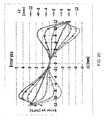
- FIG. 2C illustrates an example graph showing error that may be associated with crosstalk between two magnets such as, for example, first magnet 122 and second magnet 120.
- first magnet 122 and second magnet 120 For example, first magnet 122 and second magnet 120.
- FIG. 2B suppose an Angle "yz" is associated with a second magnet position "z2". When “Bz” is, for example, zero or a constant function of a first magnet position "z1", crosstalk may be absent.
- Crosstalk may be determined by identifying, for example, a difference between an Angle “yz” curve for "z1" not equaling zero and “z1” equaling zero. This difference may be divided, for example, by a total change in an angle associated with "z1” equaling zero when "z2" is moving through, for example, a whole stroke, resulting in a percent full scale (FS) error.
- FS percent full scale
- crosstalk may rise to, for example, 4.7% FS. It may be desirable, however, to make crosstalk as low as possible.
- a non-zero crosstalk may be corrected for based on, for example, identifying Angle "xz” and Angle “yz” and solving for the unknown positions "z1" and "z2" based on the identified angles.
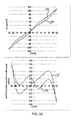
- FIG. 2D illustrates an example graph of flux densities that may be associated with the first magnet 122.
- flux densities are shown for the first magnet 122 when, for example, the second magnet 120 is not present.
- "By" may be zero which may be explained from a symmetry point of view.
- "Bz” may be almost constant which may limit the crosstalk value to 4.7%FS. If “Bz" were to be constant then crosstalk may be, for example, 0%FS which may be a design goal.
- FIG. 3 illustrates a flow chart of example acts that may be used to identify a position of a first magnet and a second magnet such as, for example, first magnet 122 and second magnet 120, respectively.
- the first magnet and the second magnet may be part of a magnetic angle position sensor such as, for example, magnetic angle position sensor 100.
- the magnetic angle position sensor may also include a sensing device such as, for example, sensing device 130.
- magnetic field components "Bx”, “By”, and “Bz” are measured.
- Magnetic field components "Bx”, “By”, and “Bz” may be measured using a sensing device such as, for example, sensing device 130.
- Magnetic field component "By” may be influenced by the second magnet.
- magnetic field component “By” may be influenced by the second magnet and not the first magnet.
- the magnetic field component “By” may be measured using the sensing device.
- Magnetic field component "Bx” may be influenced by the first magnet.
- magnetic field component “Bx” may be influenced by the first magnet and not the second magnet.
- the magnetic field component “Bx” may be measured using the sensing device.
- Angle "xz” and Angle “yz” may be identified.
- Angle “xy” and Angle “yz” may be identified based on the measured "Bx", “By”, and “Bz” magnetic components.
- the position of the first magnet (“z1") and the position of the second magnet position (“z2”) may be identified based on Angle “xz” and Angle "yz", which were identified at block 312.
- both magnets may be polarized in the same direction.
- both magnets may contribute to the magnetic field component "Bz". This may mean that a resultant residual flux density field "Br" may be higher when two magnets are used rather than one magnet. The higher field may enable smaller magnets to be used.
- FIG. 4 illustrates examples of magnets 410, 450 that may be used in magnetic angle position sensor 100.
- magnet 410 may be a cylindrically shaped.
- Arrows 416 may indicate a height of the magnet 410 and arrows 418 may indicate a length of the magnet 410.
- An example volume of magnet 410 may be 485 millimeters (mm) 3 .
- Arrow 414 may indicate a spacing between sensing device 130 and the magnet 410.
- the spacing may be such that the magnet 410 may provide a magnetic field intensity that can be measured by sensing device 130.
- Magnet 450 is an example of another magnet that may be used in a magnetic angle position sensor such as, for example, a magnetic angle position sensor 100. Magnet 450 may be conically shaped. A length of magnet 450 may be denoted by arrows 458. An example volume of magnet 450 may be 335 mm 3 .
- Arrows 454 may denote a spacing between the sensing device 130 and the magnet 450.
- the spacing indicated by arrows 454 may be such that at the end of, for example, a stroke of magnet 450 at least the minimum requirement of "Br" for the sensing device 130 is met.
- Magnet 450 may have a first width denoted by arrows 452 and a second width denoted by arrows 456.
- the first width may be a maximum width associated with the magnet 450 and may be located substantially towards the center of the magnet 450.
- the second width may be located substantially towards one or more ends of the magnet 450.
- the magnet 450 may gradually taper from the first width to the second width.
- Magnet 450 may require less material to manufacture than magnet 410 and therefore may be less expensive to produce than magnet 410.
- a "Br" associated with magnet 450 may be closer to a minimum required "Br" by the sensing device 130, thus, the magnet 450 may be not considered over designed as magnet 410 may be considered.
- FIGs. 5A-C illustrate various example graphs showing example outcomes of various parameters associated with a round (cylindrically-shaped) magnet and a cone (conically-shaped) magnet.
- Plots 520a-f show examples of outcomes associated with a cone magnet and plots 530a-f show examples of outcomes associated with a round magnet.
- the example outcomes of the cone magnet and the round magnet tend to show that the cone magnet may outperform the round magnet when used in, for example, a magnetic angle position sensor.
- Typical magnet-to-magnet distance may be less than, for example, 40 mm.
- one sensing device 130 may be used to measure Angle "xz” and Angle "yz".
- the magnetic influence/crosstalk from magnet 120 on Angle “xz” may be reduced by using Angle "yz”.
- the magnetic influence/crosstalk from magnet 122 on Angle “yz” may be reduced by using Angle "xz”.
- a similar approach may be used when the magnet-to-magnet distance is larger (e.g., 40mm to 100 mm).
- two sensing devices instead of one sensing device may be used. Now two techniques may be identified where in a first sensing device Angle_xz_1 and Angle_yz_1 are measured and in the second sensing device an Angle_xz_2 and Angle_yz_2 may be measured.
- the first technique may involve an Angle_xz_1 being mainly influenced by the first magnet.
- the magnetic influence/crosstalk from the second magnet on Angle_xz_1 may be eliminated by using an Angle yz_1.
- the Angle_xz_2 may be, for example, mainly influenced by the second magnet.
- the magnetic influence/crosstalk from the first magnet on Angle_xz_2 may be eliminated, for example, by using Angle yz_2.
- a second technique may involve an Angle_xz_1 being mainly influenced by the first magnet.
- the magnetic influence/crosstalk from the second magnet on Angle_xz_1 may be eliminated by using an Angle xz_2.
- the Angle_xz_2 may be mainly influenced by the second magnet.
- the magnetic influence/crosstalk from the first magnet on Angle_xz_2 may be eliminated, for example, by using Angle xz_1.
- FIG. 6 illustrates an example of an apparatus 600 that may implement one or more techniques described herein.
- the apparatus 600 may include magnetic angle position sensor 100 and computing device 620.
- An example embodiment of magnetic angle position sensor 100 is described above.
- Computing device 620 may include processing logic 622 and storage 624.
- Processing logic 622 may include, for example, logic for interpreting, executing, and/or otherwise processing information.
- the information may include information that may be stored in, for example, storage 624.
- Processing logic 622 may include a variety of heterogeneous hardware.
- the hardware may include, for example, some combination of one or more processors, microprocessors, field programmable gate arrays (FPGAs), application specific instruction set processors (ASIPs), application specific integrated circuits (ASICs), complex programmable logic devices (CPLDs), graphics processing units (GPUs), and/or other types of processing logic that may, for example, interpret, execute, manipulate, and/or otherwise process information.
- Processing logic 622 may comprise a single core or multiple cores.
- An example of a processor that may be used to implement processing logic 622 include, but are not limited to, an Intel® AtomTM brand processor which is available from Intel Corporation, Santa Clara, California.
- Storage 624 may provide a storage for the computing device 620.
- the storage may be a tangible non-transitory storage that may be used to store information such as, for example, computer-executable instructions and/or data that may be used by processing logic 622.
- the information may include, for example, computer-executable instructions that when executed by processing logic may perform one or more techniques described herein.
- the information may include computer-executable instructions that when executed by processing logic 622 may perform one or more acts described above with respect to FIG. 3 .
- Storage 624 may include one or memory devices that may be used to store the information.
- a memory device may support, for example, serial or random access to information stored in the memory device.
- a memory device that supports serial access to information stored in the memory device may be referred to as a serial memory device.
- a memory device that supports random access to information stored in the memory device may be referred to as a random access memory (RAM) device.
- RAM random access memory
- a memory device may be, for example, a volatile memory device or a non-volatile memory device.
- a volatile memory device may be a memory device that may lose information stored in the device after power is removed from the memory device.
- a non-volatile memory device may be a memory device that may retain information stored in the memory device after power is removed from the memory device.
- Examples of memory devices that may be used in storage 624 include, but are not limited to, a dynamic RAM (DRAM) device, flash memory device, static RAM (SRAM) device, zero-capacitor RAM (ZRAM) device, twin transistor RAM (TTRAM) device, read-only memory (ROM) device, ferroelectric transistor RAM (FeTRAM) device, magnetoresistive RAM (MRAM) device, phase change memory (PCM) device, PCM and switch (PCMS) device, nanowire-based device, resistive RAM memory (RRAM) device, and electrically erasable programmable ROM (EEPROM) device.
- DRAM dynamic RAM
- SRAM static RAM
- ZRAM zero-capacitor RAM
- TTRAM twin transistor RAM
- ROM read-only memory
- FeTRAM ferroelectric transistor RAM
- MRAM magnetoresistive RAM
- PCM phase change memory
- PCMS PCM and switch
- EEPROM electrically erasable programmable ROM
Landscapes
- Physics & Mathematics (AREA)
- General Physics & Mathematics (AREA)
- Transmission And Conversion Of Sensor Element Output (AREA)
- Measurement Of Length, Angles, Or The Like Using Electric Or Magnetic Means (AREA)
- Measuring Magnetic Variables (AREA)
Abstract
Description
- This application claims the benefit of and priority to
U.S. Provisional Patent Application No. 61/781,706 - The accompanying drawings, which are incorporated in and constitute a part of this specification, illustrate one or more embodiments described herein and, together with the description, explain these embodiments. In the drawings:
-
FIG. 1 illustrates an example of a magnetic angle position sensor having two magnets and a sensor; -
FIGs. 2A-B illustrate example graphs of an association between an angle and positions of two magnets; -
FIG. 2C illustrates an example graph showing error that may be associated with crosstalk between two magnets; -
FIG. 2D illustrates an example graph of flux densities that may be associated with a magnet; -
FIG. 3 illustrates a flow chart of example acts that may be used to identify a position of a first magnet and a second magnet; -
FIG. 4 illustrates examples of magnets that may be used in a magnetic angle position sensor; -
FIG. 5A-C illustrate various graphs showing example outcomes of various parameters associated with a round (cylindrically-shaped) magnet and a cone (conically-shaped) magnet; and -
FIG. 6 illustrates an example of an apparatus that may implement one or more techniques described herein. - The following detailed description refers to the accompanying drawings. The same reference numbers in different drawings may identify the same or similar elements. Also, the following detailed description does not limit the invention.
- Techniques described herein may be used to measure a plurality of positions associated with a plurality of magnets based on, for example, a magnetic field angle induced by the magnets. In an embodiment, a magnetic angle position sensor may include circuitry that may measure a three-dimensional (3D) field induced by the movement of the magnets. The circuitry may be incorporated in a monolithic integrated circuit (IC). The circuitry may incorporate, for example, Hall-effect techniques to measure the 3D magnetic field.
- Specifically, the circuitry may measure a magnetic flux density of magnetic fields associated with the magnets. The magnetic flux density may be applied, for example, orthogonally and in parallel to the circuitry. The circuitry may be sensitive to various magnetic field components of the magnetic fields associated with the magnets. These magnetic field components may include, for example, "Bx", "By", and/or "Bz" components, where "B" may denote a strength of a magnetic field and "x", "y", and "z" may denote a direction of the magnetic field.
-
FIG. 1 illustrates an example of a magneticangle position sensor 100 having afirst magnet 122, asecond magnet 120, and asensing device 130. The magneticangle position sensor 100 may be used to measure positions of the magnets 120,122 with respect to, for example, a position of thesensing device 130. - Note that magnetic
angle position sensor 100 is an example of a device that may incorporate one or more techniques described herein in order to identify positions of magnetic elements such as, for example, magnets. It should be noted, however, that other devices may incorporate one or more techniques described herein to identify positions of magnetic elements. For example, a device containing more than two magnets and two or more sensing devices may implement one or more techniques described herein to identify positions of one or more of the magnets contained in the device. - Referring now to
FIG. 1 , thefirst magnet 122 may be shaped as a toroid, although, as will be explained further below, other shapes may be used. Thefirst magnet 122 may include a coating to protect thefirst magnet 122. Thefirst magnet 122 may be made of a magnetic material. Suitable magnetic materials may include, for example, an iron alloy such as aluminum, nickel, and cobalt (AlNiCo); Neodymium, Ferrite, or Samarium Cobalt. Note that other suitable magnetic materials may be used. - The
second magnet 120 may also be shaped as a toroid, although, other shapes such as, for example, shapes described below may be used. Thesecond magnet 120 may also include a coating to protect thesecond magnet 120. Moreover, thesecond magnet 120 may also be made of a suitable magnetic material, for example, such as described above. - The
sensing device 130 may be a 3D Hall-effect sensor capable of identifying magnetic field components "Bx", "By", and "Bz" associated withmagnets sensing device 130 may include, for example, electronic circuitry that may be used to identify the "Bx", "By", and "Bz" components. - The
sensing device 130 may be contained in an IC. An example of a sensing device that may be used to implementsensing device 130 may include a Triaxis® series sensor IC available from Melexis, Microelectronics Integrated Systems, Ypres, Belgium. An example of a Triaxis® series sensor IC that may be used is the Melexis MLX90365 sensor IC. - The
first magnet 122 may be positioned and/or designed such that it influences a "Bx" component that may be identified (e.g., measured) by thesensing device 130 but not a "By" component identified by thesensing device 130. Thesecond magnet 120 may be positioned and/or designed such that it influences a "By" component that may be identified by thesensing device 130 but not a "Bx" component identified bysensing device 130. - For example, at an orthogonal point (e.g., 90° point, but the angle may be different from 90°), the "By" component measured by
sensing device 130 may be influenced by thesecond magnet 120 but not thefirst magnet 122. Also at the orthogonal point, the "Bx" component measured by thesensing device 130 may be influenced by thefirst magnet 122 and not thesecond magnet 120. - "Bz" component readings that may be identified by
sensing device 130 may be used to, for example, compensate for temperature and/or drift effects that may be associated with the operation of magneticangle position sensor 100. The "Bz" component may be perpendicular to, for example, the "Bx" and "By" components. "Bz" may be influenced by both thefirst magnet 122 and thesecond magnet 120. For example, the position of thefirst magnet 122 and the position of thesecond magnet 120 may influence "Bz". - An Angle "xz" and an Angle "yz" may be identified using "Bx", "By", and "Bz". For example, Angle "xz" may be identified using the formula: Angle "xz" = arctan(Bx/Bz). Angle "yz" may be identified, for example, using the formula: Angle "yz" = arctan(By/Bz). As will be described further below, Angle "xz" may be used to identify a position of
magnet 122 and Angle "yz" may be used to identify a position ofmagnet 120. - Note that a position of
magnet 120 and a position ofmagnet 122 may involve various factors. These factors may include, for example, a shape of themagnets magnets sensing device 130; a distance between themagnets sensing device 130 with respect tomagnets - Magnetic
angle position sensor 100 may be implemented in various apparatuses. An example of an apparatus that may implement a magnetic angle position sensor such as, for example, magneticangle position sensor 100 may include a double clutch transmission (DCT). It should be noted that other apparatuses may implement magnetic angle position sensors that incorporate one or more techniques described herein. An example of anapparatus 600 that may implement magneticangle position sensor 100 will be described further below with respect toFIG. 6 . -
FIG. 2A illustrates an example graph of an association between Angle "xz" and positions ofmagnets FIG. 2A , a position offirst magnet 122 may be identified by the variable "z1". A position ofsecond magnet 120 may be identified by the variable "z2". -
FIG. 2B illustrates an example graph of an association between Angle "yz" and positions ofmagnets FIG. 2B , a position offirst magnet 122 may be identified by the variable "z1" and a position of asecond magnet 120 may be identified by the variable "z2". - By combining both graphs 2A and 2B, the two unknown positions "z1" and 'z2" may be identified knowing Angle "xz" and Angle "yz".
-
FIG. 2C illustrates an example graph showing error that may be associated with crosstalk between two magnets such as, for example,first magnet 122 andsecond magnet 120. Referring toFIG. 2B , suppose an Angle "yz" is associated with a second magnet position "z2". When "Bz" is, for example, zero or a constant function of a first magnet position "z1", crosstalk may be absent. - Now suppose Angle "yz" is associated with the second magnet position "z2" and Angle "yz" is calibrated when "z1" equals zero. Crosstalk may be determined by identifying, for example, a difference between an Angle "yz" curve for "z1" not equaling zero and "z1" equaling zero. This difference may be divided, for example, by a total change in an angle associated with "z1" equaling zero when "z2" is moving through, for example, a whole stroke, resulting in a percent full scale (FS) error.
- As shown in the example graph in
FIG. 2C , crosstalk may rise to, for example, 4.7% FS. It may be desirable, however, to make crosstalk as low as possible. A non-zero crosstalk may be corrected for based on, for example, identifying Angle "xz" and Angle "yz" and solving for the unknown positions "z1" and "z2" based on the identified angles. -
FIG. 2D illustrates an example graph of flux densities that may be associated with thefirst magnet 122. Referring toFIG. 2D , in the example graph, flux densities are shown for thefirst magnet 122 when, for example, thesecond magnet 120 is not present. Also in the graph, "By" may be zero which may be explained from a symmetry point of view. In addition, in the example graph, "Bz" may be almost constant which may limit the crosstalk value to 4.7%FS. If "Bz" were to be constant then crosstalk may be, for example, 0%FS which may be a design goal. -
FIG. 3 illustrates a flow chart of example acts that may be used to identify a position of a first magnet and a second magnet such as, for example,first magnet 122 andsecond magnet 120, respectively. The first magnet and the second magnet may be part of a magnetic angle position sensor such as, for example, magneticangle position sensor 100. The magnetic angle position sensor may also include a sensing device such as, for example,sensing device 130. - Referring to
FIG. 3 , atblock 310, magnetic field components "Bx", "By", and "Bz" are measured. Magnetic field components "Bx", "By", and "Bz" may be measured using a sensing device such as, for example,sensing device 130. - Magnetic field component "By" may be influenced by the second magnet. For example, at an orthogonal point, magnetic field component "By" may be influenced by the second magnet and not the first magnet. The magnetic field component "By" may be measured using the sensing device.
- Magnetic field component "Bx" may be influenced by the first magnet. For example, at the orthogonal point, magnetic field component "Bx" may be influenced by the first magnet and not the second magnet. The magnetic field component "Bx" may be measured using the sensing device.
- At
block 312, Angle "xz" and Angle "yz" may be identified. Angle "xy" and Angle "yz" may be identified based on the measured "Bx", "By", and "Bz" magnetic components. - For example, Angle "xz" may be identified based on the formula: Angle "xz" = arctan(Bx/Bz), where "Bx" and "Bz" are the magnetic components "Bx" and "Bz", respectively, measured at
block 310. In addition, for example, Angle "yz" may be identified based on the formula: Angle "yz" = arctan(By/Bz), where "By" and "Bz" are the magnetic components "By" and "Bz", respectively, measured atblock 310. - At
block 314, the position of the first magnet ("z1") and the position of the second magnet position ("z2") may be identified based on Angle "xz" and Angle "yz", which were identified atblock 312. - In a magnetic angle position sensor that utilizes, for example, two magnets, both magnets may be polarized in the same direction. Thus, both magnets may contribute to the magnetic field component "Bz". This may mean that a resultant residual flux density field "Br" may be higher when two magnets are used rather than one magnet. The higher field may enable smaller magnets to be used.
-
FIG. 4 illustrates examples ofmagnets angle position sensor 100. Referring toFIG. 4 ,magnet 410 may be a cylindrically shaped.Arrows 416 may indicate a height of themagnet 410 andarrows 418 may indicate a length of themagnet 410. An example volume ofmagnet 410 may be 485 millimeters (mm)3. -
Arrow 414 may indicate a spacing betweensensing device 130 and themagnet 410. The spacing may be such that themagnet 410 may provide a magnetic field intensity that can be measured by sensingdevice 130. - For example, a resultant field "Br" may be identified using the following formula: "Br" = sqrt(By2 + Bz2), where "sqrt" stands for the square root. If the
sensing device 130 requires a minimum resultant field "Br" of 200 Gauss, the spacing indicated byarrow 414 may be such that the end of, for example, a stroke ofmagnet 410 may meet at least this requirement. In fact, due to its design, themagnet 410 may actually provide more than a requisite "Br" for thesensing device 130 and therefore may be considered somewhat over designed. -
Magnet 450 is an example of another magnet that may be used in a magnetic angle position sensor such as, for example, a magneticangle position sensor 100.Magnet 450 may be conically shaped. A length ofmagnet 450 may be denoted byarrows 458. An example volume ofmagnet 450 may be 335 mm3. -
Arrows 454 may denote a spacing between thesensing device 130 and themagnet 450. The spacing indicated byarrows 454 may be such that at the end of, for example, a stroke ofmagnet 450 at least the minimum requirement of "Br" for thesensing device 130 is met. -
Magnet 450 may have a first width denoted byarrows 452 and a second width denoted byarrows 456. The first width may be a maximum width associated with themagnet 450 and may be located substantially towards the center of themagnet 450. The second width may be located substantially towards one or more ends of themagnet 450. Themagnet 450 may gradually taper from the first width to the second width. -
Magnet 450 may require less material to manufacture thanmagnet 410 and therefore may be less expensive to produce thanmagnet 410. In addition, a "Br" associated withmagnet 450 may be closer to a minimum required "Br" by thesensing device 130, thus, themagnet 450 may be not considered over designed asmagnet 410 may be considered. -
FIGs. 5A-C illustrate various example graphs showing example outcomes of various parameters associated with a round (cylindrically-shaped) magnet and a cone (conically-shaped) magnet.Plots 520a-f show examples of outcomes associated with a cone magnet and plots 530a-f show examples of outcomes associated with a round magnet. As can be seen by the plots illustrated inFIGs. 5A-C , the example outcomes of the cone magnet and the round magnet tend to show that the cone magnet may outperform the round magnet when used in, for example, a magnetic angle position sensor. - Typical magnet-to-magnet distance may be less than, for example, 40 mm. In this case one
sensing device 130 may be used to measure Angle "xz" and Angle "yz". The magnetic influence/crosstalk frommagnet 120 on Angle "xz" may be reduced by using Angle "yz". The magnetic influence/crosstalk frommagnet 122 on Angle "yz" may be reduced by using Angle "xz". - However, a similar approach may be used when the magnet-to-magnet distance is larger (e.g., 40mm to 100 mm). In this case two sensing devices instead of one sensing device may be used. Now two techniques may be identified where in a first sensing device Angle_xz_1 and Angle_yz_1 are measured and in the second sensing device an Angle_xz_2 and Angle_yz_2 may be measured.
- The first technique may involve an Angle_xz_1 being mainly influenced by the first magnet. The magnetic influence/crosstalk from the second magnet on Angle_xz_1 may be eliminated by using an Angle yz_1. The Angle_xz_2 may be, for example, mainly influenced by the second magnet. The magnetic influence/crosstalk from the first magnet on Angle_xz_2 may be eliminated, for example, by using Angle yz_2.
- A second technique may involve an Angle_xz_1 being mainly influenced by the first magnet. The magnetic influence/crosstalk from the second magnet on Angle_xz_1 may be eliminated by using an Angle xz_2. The Angle_xz_2 may be mainly influenced by the second magnet. The magnetic influence/crosstalk from the first magnet on Angle_xz_2 may be eliminated, for example, by using Angle xz_1.
-
FIG. 6 illustrates an example of anapparatus 600 that may implement one or more techniques described herein. Referring toFIG. 6 , theapparatus 600 may include magneticangle position sensor 100 andcomputing device 620. An example embodiment of magneticangle position sensor 100 is described above. -
Computing device 620 may includeprocessing logic 622 andstorage 624.Processing logic 622 may include, for example, logic for interpreting, executing, and/or otherwise processing information. The information may include information that may be stored in, for example,storage 624. -
Processing logic 622 may include a variety of heterogeneous hardware. The hardware may include, for example, some combination of one or more processors, microprocessors, field programmable gate arrays (FPGAs), application specific instruction set processors (ASIPs), application specific integrated circuits (ASICs), complex programmable logic devices (CPLDs), graphics processing units (GPUs), and/or other types of processing logic that may, for example, interpret, execute, manipulate, and/or otherwise process information.Processing logic 622 may comprise a single core or multiple cores. An example of a processor that may be used to implementprocessing logic 622 include, but are not limited to, an Intel® Atom™ brand processor which is available from Intel Corporation, Santa Clara, California. -
Storage 624 may provide a storage for thecomputing device 620. The storage may be a tangible non-transitory storage that may be used to store information such as, for example, computer-executable instructions and/or data that may be used by processinglogic 622. The information may include, for example, computer-executable instructions that when executed by processing logic may perform one or more techniques described herein. For example, the information may include computer-executable instructions that when executed by processinglogic 622 may perform one or more acts described above with respect toFIG. 3 . -
Storage 624 may include one or memory devices that may be used to store the information. A memory device may support, for example, serial or random access to information stored in the memory device. A memory device that supports serial access to information stored in the memory device may be referred to as a serial memory device. A memory device that supports random access to information stored in the memory device may be referred to as a random access memory (RAM) device. - A memory device may be, for example, a volatile memory device or a non-volatile memory device. A volatile memory device may be a memory device that may lose information stored in the device after power is removed from the memory device. A non-volatile memory device may be a memory device that may retain information stored in the memory device after power is removed from the memory device.
- Examples of memory devices that may be used in
storage 624 include, but are not limited to, a dynamic RAM (DRAM) device, flash memory device, static RAM (SRAM) device, zero-capacitor RAM (ZRAM) device, twin transistor RAM (TTRAM) device, read-only memory (ROM) device, ferroelectric transistor RAM (FeTRAM) device, magnetoresistive RAM (MRAM) device, phase change memory (PCM) device, PCM and switch (PCMS) device, nanowire-based device, resistive RAM memory (RRAM) device, and electrically erasable programmable ROM (EEPROM) device. - The foregoing description of embodiments is intended to provide illustration and description, but is not intended to be exhaustive or to limit the invention to the precise form disclosed. Modifications and variations are possible in light of the above teachings or may be acquired from practice of the invention. For example, while a series of acts has been described above with respect to
FIG. 3 , the order of the acts may be modified in other implementations. Further, non-dependent acts may be performed in parallel. - No element, act, or instruction used herein should be construed as critical or essential to the invention unless explicitly described as such. Also, as used herein, the article "a" is intended to include one or more items. Where only one item is intended, the term "one" or similar language is used. Further, the phrase "based on" is intended to mean "based, at least in part, on" unless explicitly stated otherwise.
- It is intended that the invention not be limited to the particular embodiments disclosed above, but that the invention will include any and all particular embodiments and equivalents falling within the scope of the following appended claims.
Claims (9)
- A method comprising:measuring a plurality of magnetic field components associated with a plurality of magnets contained in a magnetic angle position sensor;identifying a first angle based on the measured magnetic field components, the first angle representing an angular position associated with a first magnet of the plurality of magnets;identifying a second angle based on the measured magnetic field components, the second angle representing an angular position associated with a second magnet of the plurality of magnets;identifying a position of the first magnet based on the identified first angle and second angle; andidentifying a position of the second magnet based on the identified first angle and second angle.
- The method of claim 1, wherein the magnetic field components include a Bx magnetic field component, a By magnetic field component, and a Bz magnetic field component.
- The method of claim 1, wherein the magnetic field components are measured using a sensing device.
- The method of claim 3, wherein the sensing device is a three-dimensional (3D) Hall-effect sensor.
- An apparatus comprising:means for measuring a plurality of magnetic field components associated with a plurality of magnets contained in a magnetic angle position sensor;means for identifying a first angle based on the measured magnetic field components, the first angle representing an angular position associated with a first magnet of the plurality of magnets;means for identifying a second angle based on the measured magnetic field components, the second angle representing an angular position associated with a second magnet of the plurality of magnets;means for identifying a position of the first magnet based on the identified first angle and second angle; andmeans for identifying a position of the second magnet based on the identified first angle and second angle.
- The apparatus of claim 5, wherein the magnetic field components include a Bx magnetic field component, a By magnetic field component, and a Bz magnetic field component.
- The apparatus of claim 5, wherein the magnetic field components are measured using a sensing device.
- The apparatus of claim 7, wherein the sensing device is a three-dimensional (3D) Hall-effect sensor.
- The apparatus of any one of claims 5 to 8, further comprising:the said plurality of magnets;a sensor providing the means for measuring a plurality of magnetic field components associated with the plurality of magnets; andprocessing logic providing:the means for identifying the first angle based on the measured magnetic field components,the means for identifying the second angle based on the measured magnetic field components,the means for identifying the position of the first magnet based on the identified first angle and second angle, andthe means for identifying the position of the second magnet based on the identified first angle and second angle.
Applications Claiming Priority (1)
| Application Number | Priority Date | Filing Date | Title |
|---|---|---|---|
| US201361781706P | 2013-03-14 | 2013-03-14 |
Publications (4)
| Publication Number | Publication Date |
|---|---|
| EP2778621A2 true EP2778621A2 (en) | 2014-09-17 |
| EP2778621A8 EP2778621A8 (en) | 2016-03-16 |
| EP2778621A3 EP2778621A3 (en) | 2017-10-25 |
| EP2778621B1 EP2778621B1 (en) | 2020-11-11 |
Family
ID=50231081
Family Applications (1)
| Application Number | Title | Priority Date | Filing Date |
|---|---|---|---|
| EP14158442.5A Active EP2778621B1 (en) | 2013-03-14 | 2014-03-07 | Magnetic Angle Position Sensor |
Country Status (5)
| Country | Link |
|---|---|
| US (1) | US9372064B2 (en) |
| EP (1) | EP2778621B1 (en) |
| JP (1) | JP6170854B2 (en) |
| KR (1) | KR20140113411A (en) |
| CN (1) | CN104048594B (en) |
Families Citing this family (16)
| Publication number | Priority date | Publication date | Assignee | Title |
|---|---|---|---|---|
| US9401621B2 (en) * | 2014-03-14 | 2016-07-26 | Lenovo (Singapore) Pte. Ltd. | Wireless charging dock with auto-positioning |
| GB201416870D0 (en) * | 2014-09-24 | 2014-11-05 | Rota Eng Ltd | Magnetic Field Generator And Position Sensing Assembly |
| US11874140B2 (en) * | 2016-02-17 | 2024-01-16 | Infineon Technologies Ag | Tapered magnet |
| US20170234699A1 (en) * | 2016-02-17 | 2017-08-17 | Infineontechnologies Ag | Tapered magnet |
| US11647678B2 (en) | 2016-08-23 | 2023-05-09 | Analog Devices International Unlimited Company | Compact integrated device packages |
| US10697800B2 (en) | 2016-11-04 | 2020-06-30 | Analog Devices Global | Multi-dimensional measurement using magnetic sensors and related systems, methods, and integrated circuits |
| US10389195B2 (en) * | 2017-07-13 | 2019-08-20 | Rosemount Aerospace Inc. | Annular magnets for rotor position estimation |
| US11628275B2 (en) | 2018-01-31 | 2023-04-18 | Analog Devices, Inc. | Electronic devices |
| CN110726673B (en) * | 2018-07-17 | 2022-02-18 | 中国科学院福建物质结构研究所 | Optical probe for phase change detection of ferroelectric crystal and detection method thereof |
| CN109781150B (en) * | 2019-01-09 | 2021-04-09 | 福建睿能科技股份有限公司 | Control method of magnetic encoder, magnetic encoder and knitting machine |
| US11467225B2 (en) | 2019-03-08 | 2022-10-11 | Em Microelectronic-Marin Sa | Method of determining an absolute angle of a magnetic field |
| EP3705902B1 (en) * | 2019-03-08 | 2021-10-27 | EM Microelectronic-Marin SA | Method of determining an absolute angle of a magnetic field |
| CN110867093B (en) * | 2019-10-24 | 2021-04-13 | 中移(杭州)信息技术有限公司 | Parking space information detection method, system, network device and storage medium |
| EP4339633A3 (en) * | 2020-03-23 | 2024-06-19 | Melexis Technologies SA | Position sensor devices, methods and systems based on magnetic field gradients |
| DE102020114464A1 (en) * | 2020-05-29 | 2021-12-02 | Max Baermann Gesellschaft mit beschränkter Haftung | Device, in particular a joystick, for detecting the tilting of a pivot lever |
| DE102020118723B4 (en) | 2020-07-15 | 2024-02-22 | Infineon Technologies Ag | A method for determining a position of a first object in a positioning system, a positioning system and a computer program |
Family Cites Families (16)
| Publication number | Priority date | Publication date | Assignee | Title |
|---|---|---|---|---|
| JP3784248B2 (en) * | 2000-10-02 | 2006-06-07 | 株式会社ジェイテクト | Rotation angle detection device, torque sensor and steering device |
| JP2003139560A (en) * | 2001-10-30 | 2003-05-14 | Mitsubishi Electric Corp | Rotational position detector |
| US7307415B2 (en) * | 2002-02-14 | 2007-12-11 | Bvr Technologies Co. | Contactless angular position sensor and method for sensing angular position of a rotatable shaft |
| US20040017187A1 (en) * | 2002-07-24 | 2004-01-29 | Van Ostrand Kent E. | Magnetoresistive linear position sensor |
| AU2003302983A1 (en) * | 2002-12-18 | 2004-07-09 | Koninklijke Philips Electronics N.V. | Magnetic position sensor |
| JP4007313B2 (en) * | 2003-01-22 | 2007-11-14 | 株式会社村田製作所 | Angle sensor |
| JP2004264222A (en) * | 2003-03-03 | 2004-09-24 | Midori Sokki:Kk | Magnetic marker for rotation angle sensor |
| JP2005223221A (en) * | 2004-02-06 | 2005-08-18 | Denso Corp | Magnetic detection device and manufacturing method thereof |
| JP2006031399A (en) * | 2004-07-15 | 2006-02-02 | Fujitsu Component Ltd | pointing device |
| DE102008059775A1 (en) * | 2007-11-30 | 2009-06-04 | Continental Teves Ag & Co. Ohg | Absolutely measuring steering angle sensor arrangement |
| WO2009121193A1 (en) * | 2008-04-02 | 2009-10-08 | Polycontact Ag | Magnetic linear sensor arrangement |
| US8283921B2 (en) * | 2008-11-26 | 2012-10-09 | General Electric Company | Magnetoresistance sensors for position and orientation determination |
| US8797024B2 (en) * | 2011-02-01 | 2014-08-05 | Infineon Technologies Ag | Sensor |
| US20120229128A1 (en) * | 2011-03-10 | 2012-09-13 | Armin Satz | Magnetic Field Sensor |
| US8717010B2 (en) * | 2011-08-19 | 2014-05-06 | Infineon Technologies Ag | Magnetic position sensors, systems and methods |
| US20130113465A1 (en) * | 2011-11-04 | 2013-05-09 | Delphi Technologies, Inc. | Multiple function control knob assembly |
-
2014
- 2014-03-03 US US14/195,103 patent/US9372064B2/en active Active
- 2014-03-07 EP EP14158442.5A patent/EP2778621B1/en active Active
- 2014-03-12 JP JP2014048330A patent/JP6170854B2/en not_active Expired - Fee Related
- 2014-03-12 KR KR1020140028782A patent/KR20140113411A/en not_active Withdrawn
- 2014-03-14 CN CN201410155748.9A patent/CN104048594B/en active Active
Non-Patent Citations (1)
| Title |
|---|
| None |
Also Published As
| Publication number | Publication date |
|---|---|
| CN104048594B (en) | 2018-06-12 |
| JP2014178316A (en) | 2014-09-25 |
| KR20140113411A (en) | 2014-09-24 |
| CN104048594A (en) | 2014-09-17 |
| US20140266158A1 (en) | 2014-09-18 |
| JP6170854B2 (en) | 2017-07-26 |
| US9372064B2 (en) | 2016-06-21 |
| EP2778621B1 (en) | 2020-11-11 |
| EP2778621A8 (en) | 2016-03-16 |
| EP2778621A3 (en) | 2017-10-25 |
Similar Documents
| Publication | Publication Date | Title |
|---|---|---|
| US9372064B2 (en) | Method and apparatus for sensing positions of a plurality of magnets | |
| US9958511B2 (en) | Soft switching of magnetization in a magnetoresistive sensor | |
| CN104655004B (en) | Coaxial magnetic field angular transducer, system and method | |
| US10162016B2 (en) | Reduction of magnetic sensor component variation due to magnetic materials through the application of magnetic field | |
| US11460289B2 (en) | Magnetic sensor using multiple gradiometers for angle detection | |
| CN107036516B (en) | Using Cartesian coordinates for position detection with magnetic sensors | |
| US10782152B2 (en) | Magnetic field sensors and method for determining position and orientation of a magnet | |
| CN105371874B (en) | Really-phase two-dimensional magnetic field sensor | |
| US20180128648A1 (en) | Multi-dimensional measurement using magnetic sensors and related systems, methods, and integrated circuits | |
| US10670669B2 (en) | Magnetic field sensor for measuring an amplitude and a direction of a magnetic field using one or more magnetoresistance elements having reference layers with the same magnetic direction | |
| US20150160307A1 (en) | Orthogonal fluxgate sensor | |
| EP3413069B1 (en) | Device and method for measuring magnetic field using spin hall effect | |
| JP6503802B2 (en) | Magnetic sensor | |
| JP2016170167A (en) | Magnetic sensor | |
| CN112985253B (en) | Control lever comprising a single magnetic sensor for torsion angle and tilt angle detection | |
| EP3273203A1 (en) | Displacement detection device | |
| Pankrac et al. | Simple algorithms for the calculation of the intensity of the magnetic field of current loops and thin-wall air coils of a general shape using magnetic dipoles | |
| US9797963B2 (en) | Systems and methods for a magnetic target with magnetic bias field | |
| US9816838B2 (en) | Magnetoresistive angle sensor with linear sensor elements | |
| CN104678329B (en) | Magnetic field sensing device and method | |
| Huang et al. | A study on the effect of the condition number in the magnetic field mapping of the Air-Core solenoid | |
| Gillet et al. | Guidelines for designing a concentrator for high-current sensing applications with an allegro hall-effect sensor ic | |
| Sadovskov et al. | Sensors of magnetic field based on magnetoresistive effect | |
| Chen et al. | Calibration of magnetic gradient tensor measurement array in magnetic anomaly detection | |
| Rong et al. | Design and simulation analysis of a magnetic shielding box for ring laser gyroscope |
Legal Events
| Date | Code | Title | Description |
|---|---|---|---|
| 17P | Request for examination filed |
Effective date: 20140307 |
|
| AK | Designated contracting states |
Kind code of ref document: A2 Designated state(s): AL AT BE BG CH CY CZ DE DK EE ES FI FR GB GR HR HU IE IS IT LI LT LU LV MC MK MT NL NO PL PT RO RS SE SI SK SM TR |
|
| AX | Request for extension of the european patent |
Extension state: BA ME |
|
| PUAI | Public reference made under article 153(3) epc to a published international application that has entered the european phase |
Free format text: ORIGINAL CODE: 0009012 |
|
| RAP1 | Party data changed (applicant data changed or rights of an application transferred) |
Owner name: SENSATA TECHNOLOGIES, INC. |
|
| PUAL | Search report despatched |
Free format text: ORIGINAL CODE: 0009013 |
|
| AK | Designated contracting states |
Kind code of ref document: A3 Designated state(s): AL AT BE BG CH CY CZ DE DK EE ES FI FR GB GR HR HU IE IS IT LI LT LU LV MC MK MT NL NO PL PT RO RS SE SI SK SM TR |
|
| AX | Request for extension of the european patent |
Extension state: BA ME |
|
| RIC1 | Information provided on ipc code assigned before grant |
Ipc: G01D 5/14 20060101AFI20170915BHEP |
|
| STAA | Information on the status of an ep patent application or granted ep patent |
Free format text: STATUS: REQUEST FOR EXAMINATION WAS MADE |
|
| R17P | Request for examination filed (corrected) |
Effective date: 20180425 |
|
| RBV | Designated contracting states (corrected) |
Designated state(s): AL AT BE BG CH CY CZ DE DK EE ES FI FR GB GR HR HU IE IS IT LI LT LU LV MC MK MT NL NO PL PT RO RS SE SI SK SM TR |
|
| STAA | Information on the status of an ep patent application or granted ep patent |
Free format text: STATUS: EXAMINATION IS IN PROGRESS |
|
| 17Q | First examination report despatched |
Effective date: 20191004 |
|
| GRAP | Despatch of communication of intention to grant a patent |
Free format text: ORIGINAL CODE: EPIDOSNIGR1 |
|
| STAA | Information on the status of an ep patent application or granted ep patent |
Free format text: STATUS: GRANT OF PATENT IS INTENDED |
|
| INTG | Intention to grant announced |
Effective date: 20200529 |
|
| GRAS | Grant fee paid |
Free format text: ORIGINAL CODE: EPIDOSNIGR3 |
|
| GRAA | (expected) grant |
Free format text: ORIGINAL CODE: 0009210 |
|
| STAA | Information on the status of an ep patent application or granted ep patent |
Free format text: STATUS: THE PATENT HAS BEEN GRANTED |
|
| AK | Designated contracting states |
Kind code of ref document: B1 Designated state(s): AL AT BE BG CH CY CZ DE DK EE ES FI FR GB GR HR HU IE IS IT LI LT LU LV MC MK MT NL NO PL PT RO RS SE SI SK SM TR |
|
| REG | Reference to a national code |
Ref country code: GB Ref legal event code: FG4D |
|
| REG | Reference to a national code |
Ref country code: CH Ref legal event code: EP |
|
| REG | Reference to a national code |
Ref country code: AT Ref legal event code: REF Ref document number: 1333916 Country of ref document: AT Kind code of ref document: T Effective date: 20201115 |
|
| REG | Reference to a national code |
Ref country code: DE Ref legal event code: R096 Ref document number: 602014072205 Country of ref document: DE |
|
| REG | Reference to a national code |
Ref country code: IE Ref legal event code: FG4D |
|
| REG | Reference to a national code |
Ref country code: NL Ref legal event code: MP Effective date: 20201111 |
|
| REG | Reference to a national code |
Ref country code: AT Ref legal event code: MK05 Ref document number: 1333916 Country of ref document: AT Kind code of ref document: T Effective date: 20201111 |
|
| PG25 | Lapsed in a contracting state [announced via postgrant information from national office to epo] |
Ref country code: FI Free format text: LAPSE BECAUSE OF FAILURE TO SUBMIT A TRANSLATION OF THE DESCRIPTION OR TO PAY THE FEE WITHIN THE PRESCRIBED TIME-LIMIT Effective date: 20201111 Ref country code: RS Free format text: LAPSE BECAUSE OF FAILURE TO SUBMIT A TRANSLATION OF THE DESCRIPTION OR TO PAY THE FEE WITHIN THE PRESCRIBED TIME-LIMIT Effective date: 20201111 Ref country code: NO Free format text: LAPSE BECAUSE OF FAILURE TO SUBMIT A TRANSLATION OF THE DESCRIPTION OR TO PAY THE FEE WITHIN THE PRESCRIBED TIME-LIMIT Effective date: 20210211 Ref country code: PT Free format text: LAPSE BECAUSE OF FAILURE TO SUBMIT A TRANSLATION OF THE DESCRIPTION OR TO PAY THE FEE WITHIN THE PRESCRIBED TIME-LIMIT Effective date: 20210311 Ref country code: GR Free format text: LAPSE BECAUSE OF FAILURE TO SUBMIT A TRANSLATION OF THE DESCRIPTION OR TO PAY THE FEE WITHIN THE PRESCRIBED TIME-LIMIT Effective date: 20210212 |
|
| PG25 | Lapsed in a contracting state [announced via postgrant information from national office to epo] |
Ref country code: IS Free format text: LAPSE BECAUSE OF FAILURE TO SUBMIT A TRANSLATION OF THE DESCRIPTION OR TO PAY THE FEE WITHIN THE PRESCRIBED TIME-LIMIT Effective date: 20210311 Ref country code: SE Free format text: LAPSE BECAUSE OF FAILURE TO SUBMIT A TRANSLATION OF THE DESCRIPTION OR TO PAY THE FEE WITHIN THE PRESCRIBED TIME-LIMIT Effective date: 20201111 Ref country code: LV Free format text: LAPSE BECAUSE OF FAILURE TO SUBMIT A TRANSLATION OF THE DESCRIPTION OR TO PAY THE FEE WITHIN THE PRESCRIBED TIME-LIMIT Effective date: 20201111 Ref country code: PL Free format text: LAPSE BECAUSE OF FAILURE TO SUBMIT A TRANSLATION OF THE DESCRIPTION OR TO PAY THE FEE WITHIN THE PRESCRIBED TIME-LIMIT Effective date: 20201111 Ref country code: AT Free format text: LAPSE BECAUSE OF FAILURE TO SUBMIT A TRANSLATION OF THE DESCRIPTION OR TO PAY THE FEE WITHIN THE PRESCRIBED TIME-LIMIT Effective date: 20201111 Ref country code: BG Free format text: LAPSE BECAUSE OF FAILURE TO SUBMIT A TRANSLATION OF THE DESCRIPTION OR TO PAY THE FEE WITHIN THE PRESCRIBED TIME-LIMIT Effective date: 20210211 |
|
| REG | Reference to a national code |
Ref country code: LT Ref legal event code: MG9D |
|
| PG25 | Lapsed in a contracting state [announced via postgrant information from national office to epo] |
Ref country code: HR Free format text: LAPSE BECAUSE OF FAILURE TO SUBMIT A TRANSLATION OF THE DESCRIPTION OR TO PAY THE FEE WITHIN THE PRESCRIBED TIME-LIMIT Effective date: 20201111 |
|
| PG25 | Lapsed in a contracting state [announced via postgrant information from national office to epo] |
Ref country code: RO Free format text: LAPSE BECAUSE OF FAILURE TO SUBMIT A TRANSLATION OF THE DESCRIPTION OR TO PAY THE FEE WITHIN THE PRESCRIBED TIME-LIMIT Effective date: 20201111 Ref country code: SK Free format text: LAPSE BECAUSE OF FAILURE TO SUBMIT A TRANSLATION OF THE DESCRIPTION OR TO PAY THE FEE WITHIN THE PRESCRIBED TIME-LIMIT Effective date: 20201111 Ref country code: LT Free format text: LAPSE BECAUSE OF FAILURE TO SUBMIT A TRANSLATION OF THE DESCRIPTION OR TO PAY THE FEE WITHIN THE PRESCRIBED TIME-LIMIT Effective date: 20201111 Ref country code: EE Free format text: LAPSE BECAUSE OF FAILURE TO SUBMIT A TRANSLATION OF THE DESCRIPTION OR TO PAY THE FEE WITHIN THE PRESCRIBED TIME-LIMIT Effective date: 20201111 Ref country code: CZ Free format text: LAPSE BECAUSE OF FAILURE TO SUBMIT A TRANSLATION OF THE DESCRIPTION OR TO PAY THE FEE WITHIN THE PRESCRIBED TIME-LIMIT Effective date: 20201111 Ref country code: SM Free format text: LAPSE BECAUSE OF FAILURE TO SUBMIT A TRANSLATION OF THE DESCRIPTION OR TO PAY THE FEE WITHIN THE PRESCRIBED TIME-LIMIT Effective date: 20201111 |
|
| REG | Reference to a national code |
Ref country code: DE Ref legal event code: R097 Ref document number: 602014072205 Country of ref document: DE |
|
| PG25 | Lapsed in a contracting state [announced via postgrant information from national office to epo] |
Ref country code: DK Free format text: LAPSE BECAUSE OF FAILURE TO SUBMIT A TRANSLATION OF THE DESCRIPTION OR TO PAY THE FEE WITHIN THE PRESCRIBED TIME-LIMIT Effective date: 20201111 |
|
| PLBE | No opposition filed within time limit |
Free format text: ORIGINAL CODE: 0009261 |
|
| STAA | Information on the status of an ep patent application or granted ep patent |
Free format text: STATUS: NO OPPOSITION FILED WITHIN TIME LIMIT |
|
| 26N | No opposition filed |
Effective date: 20210812 |
|
| PG25 | Lapsed in a contracting state [announced via postgrant information from national office to epo] |
Ref country code: AL Free format text: LAPSE BECAUSE OF FAILURE TO SUBMIT A TRANSLATION OF THE DESCRIPTION OR TO PAY THE FEE WITHIN THE PRESCRIBED TIME-LIMIT Effective date: 20201111 Ref country code: MC Free format text: LAPSE BECAUSE OF FAILURE TO SUBMIT A TRANSLATION OF THE DESCRIPTION OR TO PAY THE FEE WITHIN THE PRESCRIBED TIME-LIMIT Effective date: 20201111 Ref country code: NL Free format text: LAPSE BECAUSE OF FAILURE TO SUBMIT A TRANSLATION OF THE DESCRIPTION OR TO PAY THE FEE WITHIN THE PRESCRIBED TIME-LIMIT Effective date: 20201111 Ref country code: IT Free format text: LAPSE BECAUSE OF FAILURE TO SUBMIT A TRANSLATION OF THE DESCRIPTION OR TO PAY THE FEE WITHIN THE PRESCRIBED TIME-LIMIT Effective date: 20201111 |
|
| REG | Reference to a national code |
Ref country code: CH Ref legal event code: PL |
|
| PG25 | Lapsed in a contracting state [announced via postgrant information from national office to epo] |
Ref country code: ES Free format text: LAPSE BECAUSE OF FAILURE TO SUBMIT A TRANSLATION OF THE DESCRIPTION OR TO PAY THE FEE WITHIN THE PRESCRIBED TIME-LIMIT Effective date: 20201111 Ref country code: SI Free format text: LAPSE BECAUSE OF FAILURE TO SUBMIT A TRANSLATION OF THE DESCRIPTION OR TO PAY THE FEE WITHIN THE PRESCRIBED TIME-LIMIT Effective date: 20201111 |
|
| REG | Reference to a national code |
Ref country code: BE Ref legal event code: MM Effective date: 20210331 |
|
| PG25 | Lapsed in a contracting state [announced via postgrant information from national office to epo] |
Ref country code: IE Free format text: LAPSE BECAUSE OF NON-PAYMENT OF DUE FEES Effective date: 20210307 Ref country code: FR Free format text: LAPSE BECAUSE OF NON-PAYMENT OF DUE FEES Effective date: 20210331 Ref country code: CH Free format text: LAPSE BECAUSE OF NON-PAYMENT OF DUE FEES Effective date: 20210331 Ref country code: LI Free format text: LAPSE BECAUSE OF NON-PAYMENT OF DUE FEES Effective date: 20210331 Ref country code: LU Free format text: LAPSE BECAUSE OF NON-PAYMENT OF DUE FEES Effective date: 20210307 |
|
| PG25 | Lapsed in a contracting state [announced via postgrant information from national office to epo] |
Ref country code: IS Free format text: LAPSE BECAUSE OF FAILURE TO SUBMIT A TRANSLATION OF THE DESCRIPTION OR TO PAY THE FEE WITHIN THE PRESCRIBED TIME-LIMIT Effective date: 20210311 |
|
| PG25 | Lapsed in a contracting state [announced via postgrant information from national office to epo] |
Ref country code: BE Free format text: LAPSE BECAUSE OF NON-PAYMENT OF DUE FEES Effective date: 20210331 |
|
| PG25 | Lapsed in a contracting state [announced via postgrant information from national office to epo] |
Ref country code: HU Free format text: LAPSE BECAUSE OF FAILURE TO SUBMIT A TRANSLATION OF THE DESCRIPTION OR TO PAY THE FEE WITHIN THE PRESCRIBED TIME-LIMIT; INVALID AB INITIO Effective date: 20140307 |
|
| PGFP | Annual fee paid to national office [announced via postgrant information from national office to epo] |
Ref country code: DE Payment date: 20230329 Year of fee payment: 10 |
|
| PG25 | Lapsed in a contracting state [announced via postgrant information from national office to epo] |
Ref country code: CY Free format text: LAPSE BECAUSE OF FAILURE TO SUBMIT A TRANSLATION OF THE DESCRIPTION OR TO PAY THE FEE WITHIN THE PRESCRIBED TIME-LIMIT Effective date: 20201111 |
|
| P01 | Opt-out of the competence of the unified patent court (upc) registered |
Effective date: 20230708 |
|
| PG25 | Lapsed in a contracting state [announced via postgrant information from national office to epo] |
Ref country code: MK Free format text: LAPSE BECAUSE OF FAILURE TO SUBMIT A TRANSLATION OF THE DESCRIPTION OR TO PAY THE FEE WITHIN THE PRESCRIBED TIME-LIMIT Effective date: 20201111 |
|
| PG25 | Lapsed in a contracting state [announced via postgrant information from national office to epo] |
Ref country code: TR Free format text: LAPSE BECAUSE OF FAILURE TO SUBMIT A TRANSLATION OF THE DESCRIPTION OR TO PAY THE FEE WITHIN THE PRESCRIBED TIME-LIMIT Effective date: 20201111 |
|
| PG25 | Lapsed in a contracting state [announced via postgrant information from national office to epo] |
Ref country code: MT Free format text: LAPSE BECAUSE OF FAILURE TO SUBMIT A TRANSLATION OF THE DESCRIPTION OR TO PAY THE FEE WITHIN THE PRESCRIBED TIME-LIMIT Effective date: 20201111 |
|
| REG | Reference to a national code |
Ref country code: DE Ref legal event code: R119 Ref document number: 602014072205 Country of ref document: DE |
|
| PG25 | Lapsed in a contracting state [announced via postgrant information from national office to epo] |
Ref country code: DE Free format text: LAPSE BECAUSE OF NON-PAYMENT OF DUE FEES Effective date: 20241001 |
|
| PG25 | Lapsed in a contracting state [announced via postgrant information from national office to epo] |
Ref country code: DE Free format text: LAPSE BECAUSE OF NON-PAYMENT OF DUE FEES Effective date: 20241001 |
|
| REG | Reference to a national code |
Ref country code: GB Ref legal event code: 732E Free format text: REGISTERED BETWEEN 20250619 AND 20250625 |
|
| PGFP | Annual fee paid to national office [announced via postgrant information from national office to epo] |
Ref country code: GB Payment date: 20260324 Year of fee payment: 13 |