EP2778538A1 - Cooktop burner mounting system - Google Patents
Cooktop burner mounting system Download PDFInfo
- Publication number
- EP2778538A1 EP2778538A1 EP14159755.9A EP14159755A EP2778538A1 EP 2778538 A1 EP2778538 A1 EP 2778538A1 EP 14159755 A EP14159755 A EP 14159755A EP 2778538 A1 EP2778538 A1 EP 2778538A1
- Authority
- EP
- European Patent Office
- Prior art keywords
- holder
- bracket
- gas
- cooking appliance
- support member
- Prior art date
- Legal status (The legal status is an assumption and is not a legal conclusion. Google has not performed a legal analysis and makes no representation as to the accuracy of the status listed.)
- Granted
Links
Images

Classifications
-
- F—MECHANICAL ENGINEERING; LIGHTING; HEATING; WEAPONS; BLASTING
- F24—HEATING; RANGES; VENTILATING
- F24C—DOMESTIC STOVES OR RANGES ; DETAILS OF DOMESTIC STOVES OR RANGES, OF GENERAL APPLICATION
- F24C3/00—Stoves or ranges for gaseous fuels
- F24C3/08—Arrangement or mounting of burners
-
- B—PERFORMING OPERATIONS; TRANSPORTING
- B23—MACHINE TOOLS; METAL-WORKING NOT OTHERWISE PROVIDED FOR
- B23P—METAL-WORKING NOT OTHERWISE PROVIDED FOR; COMBINED OPERATIONS; UNIVERSAL MACHINE TOOLS
- B23P11/00—Connecting or disconnecting metal parts or objects by metal-working techniques not otherwise provided for
-
- F—MECHANICAL ENGINEERING; LIGHTING; HEATING; WEAPONS; BLASTING
- F23—COMBUSTION APPARATUS; COMBUSTION PROCESSES
- F23D—BURNERS
- F23D14/00—Burners for combustion of a gas, e.g. of a gas stored under pressure as a liquid
- F23D14/02—Premix gas burners, i.e. in which gaseous fuel is mixed with combustion air upstream of the combustion zone
- F23D14/04—Premix gas burners, i.e. in which gaseous fuel is mixed with combustion air upstream of the combustion zone induction type, e.g. Bunsen burner
- F23D14/06—Premix gas burners, i.e. in which gaseous fuel is mixed with combustion air upstream of the combustion zone induction type, e.g. Bunsen burner with radial outlets at the burner head
-
- F—MECHANICAL ENGINEERING; LIGHTING; HEATING; WEAPONS; BLASTING
- F24—HEATING; RANGES; VENTILATING
- F24C—DOMESTIC STOVES OR RANGES ; DETAILS OF DOMESTIC STOVES OR RANGES, OF GENERAL APPLICATION
- F24C3/00—Stoves or ranges for gaseous fuels
- F24C3/08—Arrangement or mounting of burners
- F24C3/085—Arrangement or mounting of burners on ranges
-
- Y—GENERAL TAGGING OF NEW TECHNOLOGICAL DEVELOPMENTS; GENERAL TAGGING OF CROSS-SECTIONAL TECHNOLOGIES SPANNING OVER SEVERAL SECTIONS OF THE IPC; TECHNICAL SUBJECTS COVERED BY FORMER USPC CROSS-REFERENCE ART COLLECTIONS [XRACs] AND DIGESTS
- Y10—TECHNICAL SUBJECTS COVERED BY FORMER USPC
- Y10T—TECHNICAL SUBJECTS COVERED BY FORMER US CLASSIFICATION
- Y10T29/00—Metal working
- Y10T29/49—Method of mechanical manufacture
- Y10T29/49826—Assembling or joining
Definitions
- the present invention pertains to the art of cooking and, more particularly, to a mounting assembly employing a turn and lock feature for securing a gas cooktop burner to support structure.
- the cooktop can be provided as part of a range or separately mounted in a countertop.
- a plurality of burners are mounted at spaced locations about a top of the range.
- the burners are mounted in openings formed in the cooktop.
- the burners can actually be sealed to the cooktop to provide a streamlined appearance to facilitate cleaning and maintenance.
- the burners are generally mounted to structure below the cooktop and project through the openings.
- the present invention is directed to the mounting of a burner in a gas cooking appliance. More specifically, a turn and lock mechanism is employed for mounting a burner to a support member below a cooktop. The turn and lock mechanism is actually established between the support member and a holder attached to the burner. More specifically, the holder and support member include interengaging structure, allowing the holder to be initially attached to and then twist secured upon the support member. In making this connection, locating structure is provided to assure the holder is appropriately positioned for proper alignment of the overall turn and lock mechanism. Furthermore, upon twisting the holder relative to the support member, locking structure retains the holder in a desired, operational position.
- the locating structure is constituted by a locator element which extends into an opening in the support member, with the locator element establishing a rotational axis for the holder.
- the turn and lock mechanism includes a pair of spaced, arcuate slots formed in the support member, with each slot having an enlarged diametric portion and a reduced diametric portion.
- the holder is provided with two spaced projections, such as established by fasteners extending from or molded geometry on the holder.
- the locking structure includes a locking member which is received in an opening formed in the support member upon rotation of the holder to the operational position.
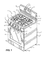
- cooking appliance 2 takes the form of a free-standing gas range.
- Range 2 includes a cabinet 4 having a front panel portion 5, opposing side panel portions 6, a bottom portion 7, a range top 8 and a main back panel 9.
- range top 8 can take on various forms.
- range top 8 is provided with five gas burner elements 11-15, i.e., four outer quadrant gas burner elements 11-14 and a central gas burner element 15, which are covered by left and right, mirror image burner grates 17 and 18.
- cabinet 4 further includes a front control surface 20 supporting a plurality of control knobs 21-25 for controlling the activation/de-activation of gas burners 11-15 respectively. Furthermore, cabinet 4 includes an upstanding control panel 30 arranged at an upper rear portion 31 of cabinet 4. In the embodiment shown, control panel 30 includes a central control and display unit, generally indicated at 35. Control panel 30 is provided above an exhaust outlet opening 37 extending across upper rear portion 31 and having an associated exhaust deflector 38 for directing an exhaust airflow away from control panel 30 and central control and display 35.
- control and display unit 35 is provided for use in controlling an oven 40 of range 2.
- control and display unit 35 includes a first control section 41 for selecting a desired cooking operation for oven 40.
- control and display unit 35 could enable a user to select between warm, convection bake, bake, convection broil, broil and cleaning operations.
- control and display unit 35 also includes a second control section 42 which defines a numeric key pad.
- control panel 30 can vary without departing from the invention.
- control panel 30 can provide for other operations known in the art.
- control and display unit 35 further includes a central display 44 for conveying information to and verifying input/operational parameters to a user.
- oven 40 includes an oven cavity 45 and has associated therewith a door 50 which can be pivoted by means of a handle 53.
- Door 50 preferably includes a plurality of vents 54 arranged behind handle 53 and a window 55 for viewing the contents of oven cavity 45 when door 50 is closed.
- a lower face panel 58 Arranged below door 50 and extending across cabinet 4 is a lower face panel 58.
- range 2 is adapted to be mounted upon a supporting surface, such as a kitchen floor or the like. More specifically, a plurality of leg members, two of which are indicated in Figure 1 at 60 and 61, extend from bottom portion 7 at front and rear portions of cabinet 4, along side panel 6. Of course, corresponding leg members 60 and 61 are also provided on the opposing side of range 2. In any event, the various leg members 60 and 61 are preferably vertically adjustable to also act as levelers for range 2. Such leg leveler arrangements are widely known in the art of appliances, including ranges, dishwashers and refrigerators. At this point, it should be noted that the above-referenced structure is known in the art and has been shown and described for the sake of completeness.
- the invention is actually directed to a mounting system for one or more of burners 11-15 for cooktop 8, particularly a mounting system including a turn and lock mechanism generally indicated at 70 for securing both burner 13 and a gas supply line 72 regulated through control knob 24 as will be more fully discussed below.
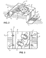
- the turn and lock mechanism 70 includes a support member in the form of a bracket 80 having base flanges 83 and 84. Projecting from base flanges 83 and 84 are upstanding legs 86 and 87 respectively. Upstanding legs 86 and 87 are interconnected by an upper cross plate 89. As shown in these figures, various internal gusset supports, such as that indicated at 92, can be provided between the base flanges 83 and 84 and upstanding legs 86 and 87, as well as between upstanding legs 86 and 87 and cross plate 89. Each of the base flanges 83 and 84 is preferably formed with at least one aperture 95, 96 for securing bracket 80 to structure below range top 8, such as a burner box indicated at 99 in Figure 2 .
- bracket 80 includes a locator opening 102 which is shown to be centrally located in cross plate 89. Radially spaced from locator opening 102 is a pair of arcuate slots 105 and 106, with each slot 105, 106 including an enlarged diametric portion 109 and a smaller or reduced diametric portion 110. About reduced diametric portion 110, cross plate 89 is formed with a concave wall 113 which, as indicated in these figures, extends completely about reduced diametric portion 110 and tapers into enlarged diametric portion 109. Also arranged along cross plate 89, at a location spaced from arcuate slots 105 and 106 as well as locator opening 102, is an arcuate recess 117. Provided within arcuate recess 117 is a lock opening 119.
- holder 126 includes a main body portion 129 from which project a pair of side flanges 133 and 134. Each side flange 133, 134 is provided with an associated mounting boss 137 having a bore 138. Main body portion 129 also includes a central boss 141 which terminates in a locking member 142. Adjacent locking member 142 is a further mounting boss 143 including a through hole 144.
- the mounting bosses 137 in the side flanges 133 and 134, as well as the mounting boss 143, are used to attach a respective burner 11-15 to holder 126.
- mechanical fasteners (not shown) are provided to extend through at least the bore 138 of each mounting boss 137 and, typically for larger size burners such as burner 12, an additional mechanical fastener (not shown) also extends within through hole 144 of mounting boss 143 such that the respective burner 11-15 is fixedly secured to holder 126.
- extension 145 Extending from main body portion 129 of holder 126 is a cantilevered extension 145. As shown, extension 145 is split or bifurcated so as to define arms 147 and 148. Between arms 147 and 148 are established mounting ports 149 and 150. Although not shown in this figure, ports 149 and 150 are utilized to secure one or more igniters for the respective gas burner 11-15 secured to holder 126.
- holder 126 is formed with central port 153 extending into main body portion 129 between side flanges 133 and 134. Central port 153 is configured to receive gas supply line 72.
- holder 126 includes a wing 160 extending from main body portion 129. Wing 160 has extending therefrom a locating element 163 and, spaced from locating element 163, is provided a pair of projections 168 and 169. In the embodiment illustrated, projections 168 and 169 are established by mechanical fasteners secured to wing 160. However, as holder 126 is preferably molded of plastic, it is equally possible to integrally form projections 168 and 169 as molded geometry of holder 126.
- bracket 80 and holder 126 combine to establish turn and lock mechanism 70 and are used in combination to mount a respective one of burners 11-15 to range top 8.
- This overall mounting arrangement is designed to minimize the labor associated with mounting burners 11-15 and to establish a mounting system which will not only enable technicians to readily remove a given burner 11-15 from range top 8 for servicing purposes but also ease in overall assembly process during the manufacture of cooking appliance 2.
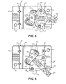
- Figures 5 and 6 reference will be made to Figures 5 and 6 in describing the interaction between bracket 80 and holder 126 when mounting a given burner 11-15.
- holder 126 is initially positioned upon bracket 80 such that locating element 163 is received within locater opening 102, while projections 168 and 169 are received within a respective enlarged diametric portion 109 of a respective arcuate slot 105, 106.
- burners 11-15 would first be mounted to holder 126 in the manner described above prior to mounting holder 126 on bracket 80.
- the particular burner 11-15 has not been shown in these figures for clarity purposes and to enable better characterization of the turn and lock mechanism of the invention.
- locking member 142 also becomes positioned within arcuate recess 117.
- holder 126 can be rotated relative to bracket 80, with locating element 163 establishing a rotational axis for holder 126. Therefore, with locating element 163 rotating within locator opening 102, projections 168 and 169 will be led from the enlarged diametric portion 109 to the reduced diametric portion 110 of a respective arcuate slot 105, 106. As projections 168 and 169 move toward a respective reduced diametric portion 110, an engagement is made between each projection 168 and 169 and a respective concave wall 113 which causes holder 126 to actually be drawn against bracket 80. At the same time, locking member 142 will shift within arcuate recess 117 toward lock opening 119. Continued rotation of holder 126 causes projections 168 and 169 to be fully positioned and retained within a respective reduced diametric portion 110, at which point lock element 142 reaches and extends into lock opening 119 as illustrated in Figure 6 .
- the cooktop burner mounting system of the invention enables a gas burner, as well as its associated gas supply line, to be mounted to a cooktop with a minimal amount of labor, yet establishes a reliable connection while enabling the burner to be conveniently removed for replacement or other purposes.
- the invention has been described in connection with mounting burners to a range top, the invention is equally applicable for use in mounting burners to support structure fixed below any type of cooktop.
- the interengaging elements between the support structure and the holder could be reversed.
- the locking member and locating element could be provided on the support structure and be received in openings provided in the holder while still performing the desired turn and lock functions.
- the support structure could take other forms.
- the bracket need not be formed as a separate element but could be integrated into the burner box itself such that the burner box actually establishes the bracket and the holder is mounted directly onto the burner box.
- other support structure such as cross rails, could be utilized, particularly if a hard tool burner box is not employed. Therefore, it is simply important to note that the mounting system of the invention includes support structure fixed below a cooktop.
Landscapes
- Engineering & Computer Science (AREA)
- Mechanical Engineering (AREA)
- Chemical & Material Sciences (AREA)
- Combustion & Propulsion (AREA)
- General Engineering & Computer Science (AREA)
- Gas Burners (AREA)
Abstract
Description
- The present invention pertains to the art of cooking and, more particularly, to a mounting assembly employing a turn and lock feature for securing a gas cooktop burner to support structure.
- In the art of cooking, both gas and electric cooktops are commonplace. The cooktop can be provided as part of a range or separately mounted in a countertop. In the case of a gas range, a plurality of burners are mounted at spaced locations about a top of the range. In most cases, the burners are mounted in openings formed in the cooktop. In some designs, the burners can actually be sealed to the cooktop to provide a streamlined appearance to facilitate cleaning and maintenance. In other designs, the burners are generally mounted to structure below the cooktop and project through the openings. For instance, it is known to mount a bracket to a burner box below the cooktop and secure a burner, as well as an end portion of a gas supply line, to the bracket, specifically through the use of a plurality of mechanical fasteners. Although effective and reliable, such a mounting arrangement is quite labor intensive in connection with the overall assembly of the cooking appliance. The invention seeks to address this situation by presenting an alternative burner mounting arrangement.
- The present invention is directed to the mounting of a burner in a gas cooking appliance. More specifically, a turn and lock mechanism is employed for mounting a burner to a support member below a cooktop. The turn and lock mechanism is actually established between the support member and a holder attached to the burner. More specifically, the holder and support member include interengaging structure, allowing the holder to be initially attached to and then twist secured upon the support member. In making this connection, locating structure is provided to assure the holder is appropriately positioned for proper alignment of the overall turn and lock mechanism. Furthermore, upon twisting the holder relative to the support member, locking structure retains the holder in a desired, operational position.
- In a particular embodiment of the invention, the locating structure is constituted by a locator element which extends into an opening in the support member, with the locator element establishing a rotational axis for the holder. In addition, the turn and lock mechanism includes a pair of spaced, arcuate slots formed in the support member, with each slot having an enlarged diametric portion and a reduced diametric portion. On the other hand, the holder is provided with two spaced projections, such as established by fasteners extending from or molded geometry on the holder. Finally, the locking structure includes a locking member which is received in an opening formed in the support member upon rotation of the holder to the operational position.
- Additional objects, features and advantages of the invention will become readily apparent from the following detailed description of preferred embodiments of the invention when taken in conjunction with the drawings wherein like reference numerals refer to corresponding parts in the several views.
-
-
Figure 1 is a perspective view of a range incorporating the cooktop burner mounting system of the present invention; -
Figure 2 is a perspective view of a bracket forming support structure of the mounting system ofFigure 1 ; -
Figure 3 is a top view of the bracket ofFigure 2 ; -
Figure 4 is a perspective view of a holder of the mounting system of the invention; -
Figure 5 is a top view showing an initial mounting position of the holder ofFigure 4 on the bracket ofFigure 3 ; and -
Figure 6 is a top view showing the mounting of the holder in an operational or locked position upon the bracket ofFigure 3 . - With initial reference to
Figure 1 , the present invention is shown incorporated into a cooking appliance generally indicated at 2. As illustrated,cooking appliance 2 takes the form of a free-standing gas range.Range 2 includes a cabinet 4 having a front panel portion 5, opposingside panel portions 6, a bottom portion 7, arange top 8 and amain back panel 9. Within the scope of the invention,range top 8 can take on various forms. In the preferred embodiment shown,range top 8 is provided with five gas burner elements 11-15, i.e., four outer quadrant gas burner elements 11-14 and a centralgas burner element 15, which are covered by left and right, mirrorimage burner grates - In the embodiment illustrated, cabinet 4 further includes a
front control surface 20 supporting a plurality of control knobs 21-25 for controlling the activation/de-activation of gas burners 11-15 respectively. Furthermore, cabinet 4 includes anupstanding control panel 30 arranged at an upperrear portion 31 of cabinet 4. In the embodiment shown,control panel 30 includes a central control and display unit, generally indicated at 35.Control panel 30 is provided above an exhaust outlet opening 37 extending across upperrear portion 31 and having an associatedexhaust deflector 38 for directing an exhaust airflow away fromcontrol panel 30 and central control anddisplay 35. - In the exemplary embodiment shown, central control and
display 35 is provided for use in controlling anoven 40 ofrange 2. Although not fully detailed in this figure, control anddisplay unit 35 includes afirst control section 41 for selecting a desired cooking operation foroven 40. By way of example, control anddisplay unit 35 could enable a user to select between warm, convection bake, bake, convection broil, broil and cleaning operations. In connection with setting desired cooking parameters, control anddisplay unit 35 also includes a second control section 42 which defines a numeric key pad. At this point, it should be realized that the arrangement and features associated withcontrol panel 30 can vary without departing from the invention. For instance, in addition to other standard controls, such as timer and clock setting elements,control panel 30 can provide for other operations known in the art. In any event, control anddisplay unit 35 further includes acentral display 44 for conveying information to and verifying input/operational parameters to a user. - As depicted,
oven 40 includes anoven cavity 45 and has associated therewith adoor 50 which can be pivoted by means of ahandle 53.Door 50 preferably includes a plurality ofvents 54 arranged behindhandle 53 and awindow 55 for viewing the contents ofoven cavity 45 whendoor 50 is closed. Arranged belowdoor 50 and extending across cabinet 4 is alower face panel 58. - In a manner known in the art,
range 2 is adapted to be mounted upon a supporting surface, such as a kitchen floor or the like. More specifically, a plurality of leg members, two of which are indicated inFigure 1 at 60 and 61, extend from bottom portion 7 at front and rear portions of cabinet 4, alongside panel 6. Of course,corresponding leg members range 2. In any event, thevarious leg members range 2. Such leg leveler arrangements are widely known in the art of appliances, including ranges, dishwashers and refrigerators. At this point, it should be noted that the above-referenced structure is known in the art and has been shown and described for the sake of completeness. Instead, the invention is actually directed to a mounting system for one or more of burners 11-15 forcooktop 8, particularly a mounting system including a turn and lock mechanism generally indicated at 70 for securing bothburner 13 and agas supply line 72 regulated throughcontrol knob 24 as will be more fully discussed below. - With reference to an embodiment of the invention shown in
Figures 2 and 3 , the turn andlock mechanism 70 includes a support member in the form of abracket 80 havingbase flanges base flanges upstanding legs legs upper cross plate 89. As shown in these figures, various internal gusset supports, such as that indicated at 92, can be provided between thebase flanges upstanding legs upstanding legs cross plate 89. Each of thebase flanges aperture bracket 80 to structure belowrange top 8, such as a burner box indicated at 99 inFigure 2 . - As also shown in these figures,
bracket 80 includes a locator opening 102 which is shown to be centrally located incross plate 89. Radially spaced fromlocator opening 102 is a pair ofarcuate slots slot diametric portion 109 and a smaller or reduceddiametric portion 110. About reduceddiametric portion 110,cross plate 89 is formed with aconcave wall 113 which, as indicated in these figures, extends completely about reduceddiametric portion 110 and tapers into enlargeddiametric portion 109. Also arranged alongcross plate 89, at a location spaced fromarcuate slots locator opening 102, is anarcuate recess 117. Provided withinarcuate recess 117 is alock opening 119. - As will be detailed more fully below,
locator opening 102,arcuate slots arcuate recess 117 and lockopening 119 are used in mounting a respective burner 11-15 to range top 8 in conjunction with aholder 126 which will now be described in detail with reference toFigure 4 . As illustrated,holder 126 includes amain body portion 129 from which project a pair ofside flanges side flange boss 137 having abore 138.Main body portion 129 also includes acentral boss 141 which terminates in a lockingmember 142.Adjacent locking member 142 is a further mountingboss 143 including a throughhole 144. As will be more detailed more fully below, the mountingbosses 137 in theside flanges boss 143, are used to attach a respective burner 11-15 toholder 126. Depending upon the size of the burner 11-15, mechanical fasteners (not shown) are provided to extend through at least thebore 138 of each mountingboss 137 and, typically for larger size burners such asburner 12, an additional mechanical fastener (not shown) also extends within throughhole 144 of mountingboss 143 such that the respective burner 11-15 is fixedly secured toholder 126. - Extending from
main body portion 129 ofholder 126 is a cantileveredextension 145. As shown,extension 145 is split or bifurcated so as to definearms arms ports ports holder 126. - As also shown in this figure,
holder 126 is formed withcentral port 153 extending intomain body portion 129 betweenside flanges Central port 153 is configured to receivegas supply line 72. In addition,holder 126 includes awing 160 extending frommain body portion 129.Wing 160 has extending therefrom a locatingelement 163 and, spaced from locatingelement 163, is provided a pair ofprojections projections wing 160. However, asholder 126 is preferably molded of plastic, it is equally possible to integrally formprojections holder 126. - As indicated above,
bracket 80 andholder 126 combine to establish turn andlock mechanism 70 and are used in combination to mount a respective one of burners 11-15 to range top 8. This overall mounting arrangement is designed to minimize the labor associated with mounting burners 11-15 and to establish a mounting system which will not only enable technicians to readily remove a given burner 11-15 fromrange top 8 for servicing purposes but also ease in overall assembly process during the manufacture ofcooking appliance 2. With this in mind, reference will be made toFigures 5 and 6 in describing the interaction betweenbracket 80 andholder 126 when mounting a given burner 11-15. With initial reference toFigure 5 ,holder 126 is initially positioned uponbracket 80 such that locatingelement 163 is received withinlocater opening 102, whileprojections diametric portion 109 of a respectivearcuate slot holder 126 in the manner described above prior to mountingholder 126 onbracket 80. The particular burner 11-15 has not been shown in these figures for clarity purposes and to enable better characterization of the turn and lock mechanism of the invention. In any case, along with locatingelement 163 being received withinlocator opening 102, lockingmember 142 also becomes positioned withinarcuate recess 117. - Once in the configuration described above,
holder 126 can be rotated relative tobracket 80, with locatingelement 163 establishing a rotational axis forholder 126. Therefore, with locatingelement 163 rotating withinlocator opening 102,projections diametric portion 109 to the reduceddiametric portion 110 of a respectivearcuate slot projections diametric portion 110, an engagement is made between eachprojection concave wall 113 which causesholder 126 to actually be drawn againstbracket 80. At the same time, lockingmember 142 will shift withinarcuate recess 117 towardlock opening 119. Continued rotation ofholder 126causes projections diametric portion 110, at whichpoint lock element 142 reaches and extends into lock opening 119 as illustrated inFigure 6 . - Based on the above, it should be readily apparent that the cooktop burner mounting system of the invention enables a gas burner, as well as its associated gas supply line, to be mounted to a cooktop with a minimal amount of labor, yet establishes a reliable connection while enabling the burner to be conveniently removed for replacement or other purposes. It should be noted that, although the invention has been described in connection with mounting burners to a range top, the invention is equally applicable for use in mounting burners to support structure fixed below any type of cooktop. In addition, it should be recognized that some or all of the interengaging elements between the support structure and the holder could be reversed. For example, the locking member and locating element could be provided on the support structure and be received in openings provided in the holder while still performing the desired turn and lock functions. Furthermore, although a separate bracket mounted to a burner box has been illustrated for purposes describing the invention, the support structure could take other forms. In particular, the bracket need not be formed as a separate element but could be integrated into the burner box itself such that the burner box actually establishes the bracket and the holder is mounted directly onto the burner box. Alternatively, other support structure, such as cross rails, could be utilized, particularly if a hard tool burner box is not employed. Therefore, it is simply important to note that the mounting system of the invention includes support structure fixed below a cooktop.
Claims (15)
- A gas cooking appliance (2) comprising:a cooktop (8);a burner box (99) arranged below the cooktop (8);a plurality of gas burners (11, 12, 13, 14, 15) arranged about the cooktop (8); anda turn and lock mechanism (70) for mounting at least one of the plurality of gas burners to the burner box (99).
- The gas cooking appliance according to claim 1, further comprising:a bracket (80) mounted to the burner box (99); anda holder (126) interposed between the bracket (80) and the at least one of the plurality of gas burners (11, 12, 13, 14, 15) to the burner box, said turn and lock mechanism fixing the holder to the bracket.
- The gas cooking appliance according to claim 2, wherein the turn and lock mechanism (70) includes interengaging structure for initially attaching the holder (126) to the bracket (80) and, upon twisting the holder relative to the bracket, securing the holder upon the bracket.
- The gas cooking appliance according to claim 3, wherein the turn and lock mechanism (70) includes a pair of spaced, arcuate slots (105, 106) formed in the bracket (80), with each slot having an enlarged diametric portion (109) and a smaller diametric portion (110).
- The gas cooking appliance according to claim 4, wherein the holder (126) is provided with at least two spaced projections, with each projection being sized so as to be receivable in a respective said enlarged diametric portion (109) and retained in a respective said smaller diametric portion (110) upon twisting the holder (126) relative to the bracket (80).
- The gas cooking appliance according to claim 5, wherein the projections are established by either fasteners extending from the holder (126) or molded geometry on the holder.
- The gas cooking appliance according to claim 2, further comprising: locating structure provided between the holder (126) and the bracket (80) to assure proper alignment of the turn and lock mechanism (70).
- The gas cooking appliance according to claim 7, wherein the locating structure is constituted by a locator element which extends from the holder (126) into an opening in the bracket, with the locator element establishing a rotational axis for the holder (126).
- The gas cooking appliance according to claim 2, further comprising: locking structure retaining the holder (126) in a desired, operational position after the holder is twisted relative to the bracket (80).
- The gas cooking appliance according to claim 9, wherein the locking structure includes a locking member which is received in an opening formed in the bracket (80) upon rotation of the holder to the operational position.
- The gas cooking appliance according to claim 2, further comprising:a gas supply line (72) routed to the at least one of the plurality of gas burners (11, 12, 13, 14, 15), wherein the holder (126) includes a hanger member, said gas supply line being attached to the holder through the hanger member.
- A method of mounting a gas burner (11, 12, 13, 14, 15) relative to a cooktop (8) of a cooking appliance (2) comprising:fixedly attaching the gas burner to a holder (126);interengaging the holder with a support member arranged below the cooktop (8); andtwisting the holder (126) relative to the support member to position the gas burner in an operational position.
- The method of claim 12, wherein interengaging the holder (126) with the support member includes positioning a pair of spaced projections extending from the holder into enlarged diametric openings (109) formed in the support member.
- The method of claim 12, further comprising: locating the holder (126) relative to the support member to assure proper alignment of the holder relative to the support member and establish a rotational axis, wherein the holder is twisted about the rotational axis.
- The method of claim 12, further comprising: locking the holder (126) relative to the support member in the operational position, wherein locking the holder is constituted by receiving a locking member (142) projecting from the holder in an opening formed in the support member upon rotation of the holder (126) to the operational position.
Applications Claiming Priority (1)
| Application Number | Priority Date | Filing Date | Title |
|---|---|---|---|
| US13/804,577 US9784454B2 (en) | 2013-03-14 | 2013-03-14 | Cooktop burner mounting system |
Publications (2)
| Publication Number | Publication Date |
|---|---|
| EP2778538A1 true EP2778538A1 (en) | 2014-09-17 |
| EP2778538B1 EP2778538B1 (en) | 2018-11-07 |
Family
ID=50277052
Family Applications (1)
| Application Number | Title | Priority Date | Filing Date |
|---|---|---|---|
| EP14159755.9A Not-in-force EP2778538B1 (en) | 2013-03-14 | 2014-03-14 | Cooktop burner mounting system |
Country Status (4)
| Country | Link |
|---|---|
| US (1) | US9784454B2 (en) |
| EP (1) | EP2778538B1 (en) |
| BR (1) | BR102014005459A2 (en) |
| MX (1) | MX2014002046A (en) |
Cited By (2)
| Publication number | Priority date | Publication date | Assignee | Title |
|---|---|---|---|---|
| ES2569222A1 (en) * | 2014-11-06 | 2016-05-09 | Bsh Electrodomésticos España, S.A. | Gas hob (Machine-translation by Google Translate, not legally binding) |
| WO2018202373A1 (en) * | 2017-05-04 | 2018-11-08 | Arcelik Anonim Sirketi | A cooktop |
Families Citing this family (8)
| Publication number | Priority date | Publication date | Assignee | Title |
|---|---|---|---|---|
| US9541294B2 (en) * | 2013-08-06 | 2017-01-10 | Whirlpool Corporation | Inner swirling flame gas burner |
| US10222069B2 (en) * | 2016-07-19 | 2019-03-05 | Whirlpool Corporation | Sliding orifice holder for a gas powered cooktop |
| US10697641B2 (en) | 2016-12-19 | 2020-06-30 | Whirlpool Corporation | Orifice holder mounting system for gas cooktop |
| EP3671041B1 (en) * | 2018-12-17 | 2024-05-22 | Electrolux Appliances Aktiebolag | Burner body and domestic appliance comprising a burner body and a metal sheet plate |
| US10704824B1 (en) | 2019-05-02 | 2020-07-07 | Haier Us Appliance Solutions, Inc. | Refrigerator casing with a mitered front corner joint |
| CN114562745B (en) * | 2022-02-24 | 2025-08-26 | 广东美的厨房电器制造有限公司 | A stove installation structure and cooking appliance thereof |
| WO2024126405A1 (en) * | 2022-12-16 | 2024-06-20 | BSH Hausgeräte GmbH | Gas cooking hob |
| US20250129919A1 (en) * | 2023-10-20 | 2025-04-24 | Astro Lighting Limited | Light fitting |
Citations (3)
| Publication number | Priority date | Publication date | Assignee | Title |
|---|---|---|---|---|
| US5152276A (en) * | 1990-12-27 | 1992-10-06 | Maytag Corporation | Sealed gas burner assembly |
| US5623917A (en) * | 1995-12-21 | 1997-04-29 | White Consolidated Industries, Inc. | Sealed burner assembly |
| US5865615A (en) * | 1997-02-12 | 1999-02-02 | Lincoln Brass Works, Inc. | Sealed burner |
Family Cites Families (36)
| Publication number | Priority date | Publication date | Assignee | Title |
|---|---|---|---|---|
| US2896704A (en) * | 1959-07-28 | Electric igniting devices for gas stoves or the like | ||
| US2600656A (en) | 1950-05-12 | 1952-06-17 | Prentiss Wabers Products Compa | Support for oven burner assemblies |
| US2991783A (en) | 1958-01-21 | 1961-07-11 | Caloric Appliance Corp | Means for locating the surface burners and the pilot burner of a cooking range |
| US3082985A (en) * | 1962-02-02 | 1963-03-26 | Charles W Herdman | Baby crib bottle holder |
| IT1125102B (en) * | 1979-02-02 | 1986-05-14 | Tecnogas Fab App | COOKING HOB PERFECTLY PARTICULARLY FOR BUILT-IN INSTALLATIONS |
| GB2112356B (en) * | 1981-12-23 | 1985-06-19 | Boughton T T Sons Ltd | Improvements in or relating to transport frames for vehicles |
| NL8202118A (en) * | 1982-05-24 | 1983-12-16 | Atag Bv Apparatenfab | GAS BURNER. |
| US4679544A (en) * | 1983-11-04 | 1987-07-14 | Modern Home Products Corp. | Threaded adjustable gas intake assembly |
| US4773384A (en) * | 1983-11-04 | 1988-09-27 | Modern Home Products Corp. | Adjustable gas intake assembly |
| US4572154A (en) | 1984-05-11 | 1986-02-25 | The Tappan Company | Gas range |
| US4676221A (en) * | 1985-09-23 | 1987-06-30 | Turco Incorporated Company | Barbecue grill with uniformly-heated heating chamber |
| US4763778A (en) * | 1986-06-23 | 1988-08-16 | Fedders Machine And Tool Co., Inc. | Easily changeable gripping head for blow-molding pallet assembly |
| US4861264A (en) * | 1988-07-21 | 1989-08-29 | Channel Products, Inc. | Gas collector electrode assembly for gas burners |
| US5249958A (en) * | 1992-11-16 | 1993-10-05 | Marquette Tool & Die Company | Two-section burner |
| US5323759A (en) * | 1993-06-11 | 1994-06-28 | Peerless Premier Appliance Company | Sealed burner mounting assembly |
| US5405263A (en) * | 1993-09-20 | 1995-04-11 | Caloric Corporation | Sealed gas burner assembly |
| US5422487A (en) * | 1994-07-27 | 1995-06-06 | Light Sources, Inc. | Waste water purification system with complementary interlocking germicidal lamp and socket construction |
| US5676539A (en) | 1996-04-22 | 1997-10-14 | Harper-Wyman Company | Gas burner mounting |
| US5859410A (en) | 1997-04-07 | 1999-01-12 | General Electric Company | Mounting system for radiant cooktop heating elements |
| US5924860A (en) | 1997-08-28 | 1999-07-20 | Harper-Wyman Company | Thickwall gas burner assembly |
| DE19742792C1 (en) | 1997-09-27 | 1998-11-19 | Schott Glas | Cooker gas-burner |
| DE19819732C1 (en) | 1998-05-02 | 1999-08-26 | Schott Glas | Mounting for gas burner into cooker surface |
| US6616369B2 (en) * | 1999-01-20 | 2003-09-09 | Flexco | Quick release delineator apparatus |
| US6173708B1 (en) * | 1999-11-15 | 2001-01-16 | Maytag Corporation | Gas burner mounting assembly for appliance with ceramic based cooktop |
| US6254381B1 (en) * | 2000-05-31 | 2001-07-03 | Maytag Corporation | Sealed gas burner electrode assembly |
| US6736631B2 (en) | 2002-03-11 | 2004-05-18 | Mueller Industries, Inc. | Sealed gas burner |
| US6817353B2 (en) * | 2003-04-10 | 2004-11-16 | Maytag Corporation | Front serviceable ignition system for a cooking appliance |
| US6817355B1 (en) * | 2003-06-13 | 2004-11-16 | Maytag Corporation | Gas burner mounting assembly for a cooking appliance having a ceramic-based cooktop |
| US7602112B2 (en) * | 2004-03-22 | 2009-10-13 | Koninklijke Philips Electronics N.V. | Assembly of a capped high-pressure discharge lamp and a lamp holder |
| US7125159B2 (en) * | 2004-04-20 | 2006-10-24 | Sea Gull Lighting Products, Inc. | Non-defeatable fluorescent adapter for incandescent fixture |
| CN1805106A (en) * | 2005-01-11 | 2006-07-19 | 海鸥照明产品有限公司 | Fluorescent lamp |
| WO2008045685A1 (en) * | 2006-10-10 | 2008-04-17 | Phillips Ronald E | Air quality containment unit |
| US9022780B2 (en) * | 2008-10-27 | 2015-05-05 | Electrolux Home Products, Inc. | Oval burner alignment method |
| US7927392B2 (en) * | 2008-10-28 | 2011-04-19 | Bha Group, Inc. | Twist and lock connection for pleated filter element with flange-to-flange locking means |
| AU2010324618B2 (en) | 2009-11-30 | 2014-11-13 | Electrolux Home Products, Inc. | Simmer plate attached to burner |
| US9541294B2 (en) * | 2013-08-06 | 2017-01-10 | Whirlpool Corporation | Inner swirling flame gas burner |
-
2013
- 2013-03-14 US US13/804,577 patent/US9784454B2/en not_active Expired - Fee Related
-
2014
- 2014-02-20 MX MX2014002046A patent/MX2014002046A/en not_active Application Discontinuation
- 2014-03-10 BR BRBR102014005459-6A patent/BR102014005459A2/en not_active Application Discontinuation
- 2014-03-14 EP EP14159755.9A patent/EP2778538B1/en not_active Not-in-force
Patent Citations (3)
| Publication number | Priority date | Publication date | Assignee | Title |
|---|---|---|---|---|
| US5152276A (en) * | 1990-12-27 | 1992-10-06 | Maytag Corporation | Sealed gas burner assembly |
| US5623917A (en) * | 1995-12-21 | 1997-04-29 | White Consolidated Industries, Inc. | Sealed burner assembly |
| US5865615A (en) * | 1997-02-12 | 1999-02-02 | Lincoln Brass Works, Inc. | Sealed burner |
Cited By (3)
| Publication number | Priority date | Publication date | Assignee | Title |
|---|---|---|---|---|
| ES2569222A1 (en) * | 2014-11-06 | 2016-05-09 | Bsh Electrodomésticos España, S.A. | Gas hob (Machine-translation by Google Translate, not legally binding) |
| WO2016071821A1 (en) * | 2014-11-06 | 2016-05-12 | BSH Hausgeräte GmbH | Gas hob |
| WO2018202373A1 (en) * | 2017-05-04 | 2018-11-08 | Arcelik Anonim Sirketi | A cooktop |
Also Published As
| Publication number | Publication date |
|---|---|
| MX2014002046A (en) | 2014-11-04 |
| EP2778538B1 (en) | 2018-11-07 |
| US9784454B2 (en) | 2017-10-10 |
| US20140261385A1 (en) | 2014-09-18 |
| BR102014005459A2 (en) | 2015-06-23 |
Similar Documents
| Publication | Publication Date | Title |
|---|---|---|
| EP2778538B1 (en) | Cooktop burner mounting system | |
| US10948200B2 (en) | System for mounting undercabinet ventilation hood | |
| US11236909B2 (en) | Orifice holder mounting system for gas cooktop | |
| EP2942567A1 (en) | Cooking appliance | |
| US10288296B2 (en) | Cooking appliance | |
| US6712066B1 (en) | Rear alignment and support system for a cooking appliance cooktop | |
| US9074404B2 (en) | Household appliance having system for aligning doors and method thereof | |
| KR101717531B1 (en) | cooking appliance | |
| US12446120B2 (en) | Mounting arrangement for over-the-range cooking appliance | |
| US9482437B2 (en) | Front frame for a cooking device | |
| US12121147B2 (en) | Mounting bracket for over-the-range cooking appliance with drill guide | |
| US12366365B2 (en) | Mounting bracket for over-the-range cooking appliance | |
| JP2018204852A (en) | Range hood panel fixture | |
| US12429229B2 (en) | Locating features for a front panel of a domestic appliance door | |
| US20190125078A1 (en) | Mounting device and domestic appliance | |
| US12241631B2 (en) | Oven handle locators for controlling door appearance | |
| US20230272917A1 (en) | Appliance door having a camera bracket locator | |
| US20240392829A1 (en) | Systems for hinge receivers in cooking appliances | |
| US20240255980A1 (en) | Systems for knob lockout on appliances | |
| US20240125482A1 (en) | Adjustable mounting system for a control panel of a home cooking appliance | |
| US20250359666A1 (en) | Built-in system including a built-in cooking appliance and a fixing device for fixing the built-in cooking appliance to a furniture unit | |
| KR20080057729A (en) | Wall-mounted microwave | |
| KR200349307Y1 (en) | A joint structure of gas pipe | |
| JPH11118160A (en) | Structure for fixing cooking appliance | |
| JP2001263751A (en) | Mounting structure for remote control transmitter for operating range hood |
Legal Events
| Date | Code | Title | Description |
|---|---|---|---|
| 17P | Request for examination filed |
Effective date: 20140314 |
|
| AK | Designated contracting states |
Kind code of ref document: A1 Designated state(s): AL AT BE BG CH CY CZ DE DK EE ES FI FR GB GR HR HU IE IS IT LI LT LU LV MC MK MT NL NO PL PT RO RS SE SI SK SM TR |
|
| AX | Request for extension of the european patent |
Extension state: BA ME |
|
| PUAI | Public reference made under article 153(3) epc to a published international application that has entered the european phase |
Free format text: ORIGINAL CODE: 0009012 |
|
| R17P | Request for examination filed (corrected) |
Effective date: 20150316 |
|
| RBV | Designated contracting states (corrected) |
Designated state(s): AL AT BE BG CH CY CZ DE DK EE ES FI FR GB GR HR HU IE IS IT LI LT LU LV MC MK MT NL NO PL PT RO RS SE SI SK SM TR |
|
| STAA | Information on the status of an ep patent application or granted ep patent |
Free format text: STATUS: EXAMINATION IS IN PROGRESS |
|
| 17Q | First examination report despatched |
Effective date: 20170818 |
|
| GRAP | Despatch of communication of intention to grant a patent |
Free format text: ORIGINAL CODE: EPIDOSNIGR1 |
|
| STAA | Information on the status of an ep patent application or granted ep patent |
Free format text: STATUS: GRANT OF PATENT IS INTENDED |
|
| INTG | Intention to grant announced |
Effective date: 20180810 |
|
| RAP1 | Party data changed (applicant data changed or rights of an application transferred) |
Owner name: WHIRLPOOL CORPORATION |
|
| GRAS | Grant fee paid |
Free format text: ORIGINAL CODE: EPIDOSNIGR3 |
|
| GRAA | (expected) grant |
Free format text: ORIGINAL CODE: 0009210 |
|
| STAA | Information on the status of an ep patent application or granted ep patent |
Free format text: STATUS: THE PATENT HAS BEEN GRANTED |
|
| AK | Designated contracting states |
Kind code of ref document: B1 Designated state(s): AL AT BE BG CH CY CZ DE DK EE ES FI FR GB GR HR HU IE IS IT LI LT LU LV MC MK MT NL NO PL PT RO RS SE SI SK SM TR |
|
| REG | Reference to a national code |
Ref country code: GB Ref legal event code: FG4D |
|
| REG | Reference to a national code |
Ref country code: CH Ref legal event code: EP Ref country code: AT Ref legal event code: REF Ref document number: 1062482 Country of ref document: AT Kind code of ref document: T Effective date: 20181115 |
|
| REG | Reference to a national code |
Ref country code: IE Ref legal event code: FG4D |
|
| REG | Reference to a national code |
Ref country code: DE Ref legal event code: R096 Ref document number: 602014035439 Country of ref document: DE |
|
| REG | Reference to a national code |
Ref country code: NL Ref legal event code: MP Effective date: 20181107 |
|
| REG | Reference to a national code |
Ref country code: LT Ref legal event code: MG4D |
|
| REG | Reference to a national code |
Ref country code: AT Ref legal event code: MK05 Ref document number: 1062482 Country of ref document: AT Kind code of ref document: T Effective date: 20181107 |
|
| PG25 | Lapsed in a contracting state [announced via postgrant information from national office to epo] |
Ref country code: HR Free format text: LAPSE BECAUSE OF FAILURE TO SUBMIT A TRANSLATION OF THE DESCRIPTION OR TO PAY THE FEE WITHIN THE PRESCRIBED TIME-LIMIT Effective date: 20181107 Ref country code: AT Free format text: LAPSE BECAUSE OF FAILURE TO SUBMIT A TRANSLATION OF THE DESCRIPTION OR TO PAY THE FEE WITHIN THE PRESCRIBED TIME-LIMIT Effective date: 20181107 Ref country code: LT Free format text: LAPSE BECAUSE OF FAILURE TO SUBMIT A TRANSLATION OF THE DESCRIPTION OR TO PAY THE FEE WITHIN THE PRESCRIBED TIME-LIMIT Effective date: 20181107 Ref country code: NO Free format text: LAPSE BECAUSE OF FAILURE TO SUBMIT A TRANSLATION OF THE DESCRIPTION OR TO PAY THE FEE WITHIN THE PRESCRIBED TIME-LIMIT Effective date: 20190207 Ref country code: LV Free format text: LAPSE BECAUSE OF FAILURE TO SUBMIT A TRANSLATION OF THE DESCRIPTION OR TO PAY THE FEE WITHIN THE PRESCRIBED TIME-LIMIT Effective date: 20181107 Ref country code: FI Free format text: LAPSE BECAUSE OF FAILURE TO SUBMIT A TRANSLATION OF THE DESCRIPTION OR TO PAY THE FEE WITHIN THE PRESCRIBED TIME-LIMIT Effective date: 20181107 Ref country code: IS Free format text: LAPSE BECAUSE OF FAILURE TO SUBMIT A TRANSLATION OF THE DESCRIPTION OR TO PAY THE FEE WITHIN THE PRESCRIBED TIME-LIMIT Effective date: 20190307 Ref country code: ES Free format text: LAPSE BECAUSE OF FAILURE TO SUBMIT A TRANSLATION OF THE DESCRIPTION OR TO PAY THE FEE WITHIN THE PRESCRIBED TIME-LIMIT Effective date: 20181107 Ref country code: BG Free format text: LAPSE BECAUSE OF FAILURE TO SUBMIT A TRANSLATION OF THE DESCRIPTION OR TO PAY THE FEE WITHIN THE PRESCRIBED TIME-LIMIT Effective date: 20190207 |
|
| PG25 | Lapsed in a contracting state [announced via postgrant information from national office to epo] |
Ref country code: GR Free format text: LAPSE BECAUSE OF FAILURE TO SUBMIT A TRANSLATION OF THE DESCRIPTION OR TO PAY THE FEE WITHIN THE PRESCRIBED TIME-LIMIT Effective date: 20190208 Ref country code: NL Free format text: LAPSE BECAUSE OF FAILURE TO SUBMIT A TRANSLATION OF THE DESCRIPTION OR TO PAY THE FEE WITHIN THE PRESCRIBED TIME-LIMIT Effective date: 20181107 Ref country code: SE Free format text: LAPSE BECAUSE OF FAILURE TO SUBMIT A TRANSLATION OF THE DESCRIPTION OR TO PAY THE FEE WITHIN THE PRESCRIBED TIME-LIMIT Effective date: 20181107 Ref country code: PT Free format text: LAPSE BECAUSE OF FAILURE TO SUBMIT A TRANSLATION OF THE DESCRIPTION OR TO PAY THE FEE WITHIN THE PRESCRIBED TIME-LIMIT Effective date: 20190307 Ref country code: AL Free format text: LAPSE BECAUSE OF FAILURE TO SUBMIT A TRANSLATION OF THE DESCRIPTION OR TO PAY THE FEE WITHIN THE PRESCRIBED TIME-LIMIT Effective date: 20181107 Ref country code: RS Free format text: LAPSE BECAUSE OF FAILURE TO SUBMIT A TRANSLATION OF THE DESCRIPTION OR TO PAY THE FEE WITHIN THE PRESCRIBED TIME-LIMIT Effective date: 20181107 |
|
| PG25 | Lapsed in a contracting state [announced via postgrant information from national office to epo] |
Ref country code: DK Free format text: LAPSE BECAUSE OF FAILURE TO SUBMIT A TRANSLATION OF THE DESCRIPTION OR TO PAY THE FEE WITHIN THE PRESCRIBED TIME-LIMIT Effective date: 20181107 Ref country code: PL Free format text: LAPSE BECAUSE OF FAILURE TO SUBMIT A TRANSLATION OF THE DESCRIPTION OR TO PAY THE FEE WITHIN THE PRESCRIBED TIME-LIMIT Effective date: 20181107 Ref country code: CZ Free format text: LAPSE BECAUSE OF FAILURE TO SUBMIT A TRANSLATION OF THE DESCRIPTION OR TO PAY THE FEE WITHIN THE PRESCRIBED TIME-LIMIT Effective date: 20181107 |
|
| REG | Reference to a national code |
Ref country code: DE Ref legal event code: R097 Ref document number: 602014035439 Country of ref document: DE |
|
| PG25 | Lapsed in a contracting state [announced via postgrant information from national office to epo] |
Ref country code: RO Free format text: LAPSE BECAUSE OF FAILURE TO SUBMIT A TRANSLATION OF THE DESCRIPTION OR TO PAY THE FEE WITHIN THE PRESCRIBED TIME-LIMIT Effective date: 20181107 Ref country code: SM Free format text: LAPSE BECAUSE OF FAILURE TO SUBMIT A TRANSLATION OF THE DESCRIPTION OR TO PAY THE FEE WITHIN THE PRESCRIBED TIME-LIMIT Effective date: 20181107 Ref country code: EE Free format text: LAPSE BECAUSE OF FAILURE TO SUBMIT A TRANSLATION OF THE DESCRIPTION OR TO PAY THE FEE WITHIN THE PRESCRIBED TIME-LIMIT Effective date: 20181107 Ref country code: SK Free format text: LAPSE BECAUSE OF FAILURE TO SUBMIT A TRANSLATION OF THE DESCRIPTION OR TO PAY THE FEE WITHIN THE PRESCRIBED TIME-LIMIT Effective date: 20181107 |
|
| PLBE | No opposition filed within time limit |
Free format text: ORIGINAL CODE: 0009261 |
|
| STAA | Information on the status of an ep patent application or granted ep patent |
Free format text: STATUS: NO OPPOSITION FILED WITHIN TIME LIMIT |
|
| 26N | No opposition filed |
Effective date: 20190808 |
|
| PG25 | Lapsed in a contracting state [announced via postgrant information from national office to epo] |
Ref country code: MC Free format text: LAPSE BECAUSE OF FAILURE TO SUBMIT A TRANSLATION OF THE DESCRIPTION OR TO PAY THE FEE WITHIN THE PRESCRIBED TIME-LIMIT Effective date: 20181107 Ref country code: SI Free format text: LAPSE BECAUSE OF FAILURE TO SUBMIT A TRANSLATION OF THE DESCRIPTION OR TO PAY THE FEE WITHIN THE PRESCRIBED TIME-LIMIT Effective date: 20181107 |
|
| REG | Reference to a national code |
Ref country code: CH Ref legal event code: PL |
|
| PG25 | Lapsed in a contracting state [announced via postgrant information from national office to epo] |
Ref country code: LU Free format text: LAPSE BECAUSE OF NON-PAYMENT OF DUE FEES Effective date: 20190314 |
|
| REG | Reference to a national code |
Ref country code: BE Ref legal event code: MM Effective date: 20190331 |
|
| PG25 | Lapsed in a contracting state [announced via postgrant information from national office to epo] |
Ref country code: IE Free format text: LAPSE BECAUSE OF NON-PAYMENT OF DUE FEES Effective date: 20190314 Ref country code: LI Free format text: LAPSE BECAUSE OF NON-PAYMENT OF DUE FEES Effective date: 20190331 Ref country code: CH Free format text: LAPSE BECAUSE OF NON-PAYMENT OF DUE FEES Effective date: 20190331 |
|
| PG25 | Lapsed in a contracting state [announced via postgrant information from national office to epo] |
Ref country code: BE Free format text: LAPSE BECAUSE OF NON-PAYMENT OF DUE FEES Effective date: 20190331 |
|
| PG25 | Lapsed in a contracting state [announced via postgrant information from national office to epo] |
Ref country code: TR Free format text: LAPSE BECAUSE OF FAILURE TO SUBMIT A TRANSLATION OF THE DESCRIPTION OR TO PAY THE FEE WITHIN THE PRESCRIBED TIME-LIMIT Effective date: 20181107 |
|
| PG25 | Lapsed in a contracting state [announced via postgrant information from national office to epo] |
Ref country code: MT Free format text: LAPSE BECAUSE OF NON-PAYMENT OF DUE FEES Effective date: 20190314 |
|
| PG25 | Lapsed in a contracting state [announced via postgrant information from national office to epo] |
Ref country code: CY Free format text: LAPSE BECAUSE OF FAILURE TO SUBMIT A TRANSLATION OF THE DESCRIPTION OR TO PAY THE FEE WITHIN THE PRESCRIBED TIME-LIMIT Effective date: 20181107 |
|
| PG25 | Lapsed in a contracting state [announced via postgrant information from national office to epo] |
Ref country code: HU Free format text: LAPSE BECAUSE OF FAILURE TO SUBMIT A TRANSLATION OF THE DESCRIPTION OR TO PAY THE FEE WITHIN THE PRESCRIBED TIME-LIMIT; INVALID AB INITIO Effective date: 20140314 |
|
| PG25 | Lapsed in a contracting state [announced via postgrant information from national office to epo] |
Ref country code: MK Free format text: LAPSE BECAUSE OF FAILURE TO SUBMIT A TRANSLATION OF THE DESCRIPTION OR TO PAY THE FEE WITHIN THE PRESCRIBED TIME-LIMIT Effective date: 20181107 |
|
| P01 | Opt-out of the competence of the unified patent court (upc) registered |
Effective date: 20230522 |
|
| PGFP | Annual fee paid to national office [announced via postgrant information from national office to epo] |
Ref country code: DE Payment date: 20240328 Year of fee payment: 11 Ref country code: GB Payment date: 20240319 Year of fee payment: 11 |
|
| PGFP | Annual fee paid to national office [announced via postgrant information from national office to epo] |
Ref country code: IT Payment date: 20240321 Year of fee payment: 11 Ref country code: FR Payment date: 20240326 Year of fee payment: 11 |
|
| REG | Reference to a national code |
Ref country code: DE Ref legal event code: R119 Ref document number: 602014035439 Country of ref document: DE |
|
| GBPC | Gb: european patent ceased through non-payment of renewal fee |
Effective date: 20250314 |
|
| PG25 | Lapsed in a contracting state [announced via postgrant information from national office to epo] |
Ref country code: DE Free format text: LAPSE BECAUSE OF NON-PAYMENT OF DUE FEES Effective date: 20251001 |
|
| PG25 | Lapsed in a contracting state [announced via postgrant information from national office to epo] |
Ref country code: GB Free format text: LAPSE BECAUSE OF NON-PAYMENT OF DUE FEES Effective date: 20250314 |
|
| PG25 | Lapsed in a contracting state [announced via postgrant information from national office to epo] |
Ref country code: FR Free format text: LAPSE BECAUSE OF NON-PAYMENT OF DUE FEES Effective date: 20250331 Ref country code: IT Free format text: LAPSE BECAUSE OF NON-PAYMENT OF DUE FEES Effective date: 20250314 |