EP2778500A1 - Verfahren zum Betreiben einer Drucktankvorrichtung und Drucktankvorrichtung - Google Patents
Verfahren zum Betreiben einer Drucktankvorrichtung und Drucktankvorrichtung Download PDFInfo
- Publication number
- EP2778500A1 EP2778500A1 EP13159212.3A EP13159212A EP2778500A1 EP 2778500 A1 EP2778500 A1 EP 2778500A1 EP 13159212 A EP13159212 A EP 13159212A EP 2778500 A1 EP2778500 A1 EP 2778500A1
- Authority
- EP
- European Patent Office
- Prior art keywords
- shut
- pressure
- pressure tank
- valve
- tank device
- Prior art date
- Legal status (The legal status is an assumption and is not a legal conclusion. Google has not performed a legal analysis and makes no representation as to the accuracy of the status listed.)
- Granted
Links
Images

Classifications
-
- F—MECHANICAL ENGINEERING; LIGHTING; HEATING; WEAPONS; BLASTING
- F17—STORING OR DISTRIBUTING GASES OR LIQUIDS
- F17C—VESSELS FOR CONTAINING OR STORING COMPRESSED, LIQUEFIED OR SOLIDIFIED GASES; FIXED-CAPACITY GAS-HOLDERS; FILLING VESSELS WITH, OR DISCHARGING FROM VESSELS, COMPRESSED, LIQUEFIED, OR SOLIDIFIED GASES
- F17C5/00—Methods or apparatus for filling containers with liquefied, solidified, or compressed gases under pressures
- F17C5/06—Methods or apparatus for filling containers with liquefied, solidified, or compressed gases under pressures for filling with compressed gases
-
- F—MECHANICAL ENGINEERING; LIGHTING; HEATING; WEAPONS; BLASTING
- F17—STORING OR DISTRIBUTING GASES OR LIQUIDS
- F17C—VESSELS FOR CONTAINING OR STORING COMPRESSED, LIQUEFIED OR SOLIDIFIED GASES; FIXED-CAPACITY GAS-HOLDERS; FILLING VESSELS WITH, OR DISCHARGING FROM VESSELS, COMPRESSED, LIQUEFIED, OR SOLIDIFIED GASES
- F17C13/00—Details of vessels or of the filling or discharging of vessels
- F17C13/04—Arrangement or mounting of valves
-
- F—MECHANICAL ENGINEERING; LIGHTING; HEATING; WEAPONS; BLASTING
- F17—STORING OR DISTRIBUTING GASES OR LIQUIDS
- F17C—VESSELS FOR CONTAINING OR STORING COMPRESSED, LIQUEFIED OR SOLIDIFIED GASES; FIXED-CAPACITY GAS-HOLDERS; FILLING VESSELS WITH, OR DISCHARGING FROM VESSELS, COMPRESSED, LIQUEFIED, OR SOLIDIFIED GASES
- F17C7/00—Methods or apparatus for discharging liquefied, solidified, or compressed gases from pressure vessels, not covered by another subclass
-
- F—MECHANICAL ENGINEERING; LIGHTING; HEATING; WEAPONS; BLASTING
- F17—STORING OR DISTRIBUTING GASES OR LIQUIDS
- F17C—VESSELS FOR CONTAINING OR STORING COMPRESSED, LIQUEFIED OR SOLIDIFIED GASES; FIXED-CAPACITY GAS-HOLDERS; FILLING VESSELS WITH, OR DISCHARGING FROM VESSELS, COMPRESSED, LIQUEFIED, OR SOLIDIFIED GASES
- F17C2205/00—Vessel construction, in particular mounting arrangements, attachments or identifications means
- F17C2205/03—Fluid connections, filters, valves, closure means or other attachments
- F17C2205/0302—Fittings, valves, filters, or components in connection with the gas storage device
- F17C2205/0323—Valves
- F17C2205/0326—Valves electrically actuated
-
- F—MECHANICAL ENGINEERING; LIGHTING; HEATING; WEAPONS; BLASTING
- F17—STORING OR DISTRIBUTING GASES OR LIQUIDS
- F17C—VESSELS FOR CONTAINING OR STORING COMPRESSED, LIQUEFIED OR SOLIDIFIED GASES; FIXED-CAPACITY GAS-HOLDERS; FILLING VESSELS WITH, OR DISCHARGING FROM VESSELS, COMPRESSED, LIQUEFIED, OR SOLIDIFIED GASES
- F17C2205/00—Vessel construction, in particular mounting arrangements, attachments or identifications means
- F17C2205/03—Fluid connections, filters, valves, closure means or other attachments
- F17C2205/0302—Fittings, valves, filters, or components in connection with the gas storage device
- F17C2205/0323—Valves
- F17C2205/0335—Check-valves or non-return valves
-
- F—MECHANICAL ENGINEERING; LIGHTING; HEATING; WEAPONS; BLASTING
- F17—STORING OR DISTRIBUTING GASES OR LIQUIDS
- F17C—VESSELS FOR CONTAINING OR STORING COMPRESSED, LIQUEFIED OR SOLIDIFIED GASES; FIXED-CAPACITY GAS-HOLDERS; FILLING VESSELS WITH, OR DISCHARGING FROM VESSELS, COMPRESSED, LIQUEFIED, OR SOLIDIFIED GASES
- F17C2205/00—Vessel construction, in particular mounting arrangements, attachments or identifications means
- F17C2205/03—Fluid connections, filters, valves, closure means or other attachments
- F17C2205/0302—Fittings, valves, filters, or components in connection with the gas storage device
- F17C2205/0338—Pressure regulators
-
- F—MECHANICAL ENGINEERING; LIGHTING; HEATING; WEAPONS; BLASTING
- F17—STORING OR DISTRIBUTING GASES OR LIQUIDS
- F17C—VESSELS FOR CONTAINING OR STORING COMPRESSED, LIQUEFIED OR SOLIDIFIED GASES; FIXED-CAPACITY GAS-HOLDERS; FILLING VESSELS WITH, OR DISCHARGING FROM VESSELS, COMPRESSED, LIQUEFIED, OR SOLIDIFIED GASES
- F17C2205/00—Vessel construction, in particular mounting arrangements, attachments or identifications means
- F17C2205/03—Fluid connections, filters, valves, closure means or other attachments
- F17C2205/0302—Fittings, valves, filters, or components in connection with the gas storage device
- F17C2205/0341—Filters
-
- F—MECHANICAL ENGINEERING; LIGHTING; HEATING; WEAPONS; BLASTING
- F17—STORING OR DISTRIBUTING GASES OR LIQUIDS
- F17C—VESSELS FOR CONTAINING OR STORING COMPRESSED, LIQUEFIED OR SOLIDIFIED GASES; FIXED-CAPACITY GAS-HOLDERS; FILLING VESSELS WITH, OR DISCHARGING FROM VESSELS, COMPRESSED, LIQUEFIED, OR SOLIDIFIED GASES
- F17C2221/00—Handled fluid, in particular type of fluid
- F17C2221/01—Pure fluids
- F17C2221/012—Hydrogen
-
- F—MECHANICAL ENGINEERING; LIGHTING; HEATING; WEAPONS; BLASTING
- F17—STORING OR DISTRIBUTING GASES OR LIQUIDS
- F17C—VESSELS FOR CONTAINING OR STORING COMPRESSED, LIQUEFIED OR SOLIDIFIED GASES; FIXED-CAPACITY GAS-HOLDERS; FILLING VESSELS WITH, OR DISCHARGING FROM VESSELS, COMPRESSED, LIQUEFIED, OR SOLIDIFIED GASES
- F17C2223/00—Handled fluid before transfer, i.e. state of fluid when stored in the vessel or before transfer from the vessel
- F17C2223/01—Handled fluid before transfer, i.e. state of fluid when stored in the vessel or before transfer from the vessel characterised by the phase
- F17C2223/0107—Single phase
- F17C2223/0123—Single phase gaseous, e.g. CNG, GNC
-
- F—MECHANICAL ENGINEERING; LIGHTING; HEATING; WEAPONS; BLASTING
- F17—STORING OR DISTRIBUTING GASES OR LIQUIDS
- F17C—VESSELS FOR CONTAINING OR STORING COMPRESSED, LIQUEFIED OR SOLIDIFIED GASES; FIXED-CAPACITY GAS-HOLDERS; FILLING VESSELS WITH, OR DISCHARGING FROM VESSELS, COMPRESSED, LIQUEFIED, OR SOLIDIFIED GASES
- F17C2223/00—Handled fluid before transfer, i.e. state of fluid when stored in the vessel or before transfer from the vessel
- F17C2223/03—Handled fluid before transfer, i.e. state of fluid when stored in the vessel or before transfer from the vessel characterised by the pressure level
- F17C2223/036—Very high pressure (>80 bar)
-
- F—MECHANICAL ENGINEERING; LIGHTING; HEATING; WEAPONS; BLASTING
- F17—STORING OR DISTRIBUTING GASES OR LIQUIDS
- F17C—VESSELS FOR CONTAINING OR STORING COMPRESSED, LIQUEFIED OR SOLIDIFIED GASES; FIXED-CAPACITY GAS-HOLDERS; FILLING VESSELS WITH, OR DISCHARGING FROM VESSELS, COMPRESSED, LIQUEFIED, OR SOLIDIFIED GASES
- F17C2225/00—Handled fluid after transfer, i.e. state of fluid after transfer from the vessel
- F17C2225/01—Handled fluid after transfer, i.e. state of fluid after transfer from the vessel characterised by the phase
- F17C2225/0107—Single phase
- F17C2225/0123—Single phase gaseous, e.g. CNG, GNC
-
- F—MECHANICAL ENGINEERING; LIGHTING; HEATING; WEAPONS; BLASTING
- F17—STORING OR DISTRIBUTING GASES OR LIQUIDS
- F17C—VESSELS FOR CONTAINING OR STORING COMPRESSED, LIQUEFIED OR SOLIDIFIED GASES; FIXED-CAPACITY GAS-HOLDERS; FILLING VESSELS WITH, OR DISCHARGING FROM VESSELS, COMPRESSED, LIQUEFIED, OR SOLIDIFIED GASES
- F17C2225/00—Handled fluid after transfer, i.e. state of fluid after transfer from the vessel
- F17C2225/03—Handled fluid after transfer, i.e. state of fluid after transfer from the vessel characterised by the pressure level
- F17C2225/036—Very high pressure, i.e. above 80 bars
-
- F—MECHANICAL ENGINEERING; LIGHTING; HEATING; WEAPONS; BLASTING
- F17—STORING OR DISTRIBUTING GASES OR LIQUIDS
- F17C—VESSELS FOR CONTAINING OR STORING COMPRESSED, LIQUEFIED OR SOLIDIFIED GASES; FIXED-CAPACITY GAS-HOLDERS; FILLING VESSELS WITH, OR DISCHARGING FROM VESSELS, COMPRESSED, LIQUEFIED, OR SOLIDIFIED GASES
- F17C2250/00—Accessories; Control means; Indicating, measuring or monitoring of parameters
- F17C2250/03—Control means
- F17C2250/032—Control means using computers
-
- F—MECHANICAL ENGINEERING; LIGHTING; HEATING; WEAPONS; BLASTING
- F17—STORING OR DISTRIBUTING GASES OR LIQUIDS
- F17C—VESSELS FOR CONTAINING OR STORING COMPRESSED, LIQUEFIED OR SOLIDIFIED GASES; FIXED-CAPACITY GAS-HOLDERS; FILLING VESSELS WITH, OR DISCHARGING FROM VESSELS, COMPRESSED, LIQUEFIED, OR SOLIDIFIED GASES
- F17C2250/00—Accessories; Control means; Indicating, measuring or monitoring of parameters
- F17C2250/06—Controlling or regulating of parameters as output values
- F17C2250/0605—Parameters
-
- F—MECHANICAL ENGINEERING; LIGHTING; HEATING; WEAPONS; BLASTING
- F17—STORING OR DISTRIBUTING GASES OR LIQUIDS
- F17C—VESSELS FOR CONTAINING OR STORING COMPRESSED, LIQUEFIED OR SOLIDIFIED GASES; FIXED-CAPACITY GAS-HOLDERS; FILLING VESSELS WITH, OR DISCHARGING FROM VESSELS, COMPRESSED, LIQUEFIED, OR SOLIDIFIED GASES
- F17C2250/00—Accessories; Control means; Indicating, measuring or monitoring of parameters
- F17C2250/06—Controlling or regulating of parameters as output values
- F17C2250/0605—Parameters
- F17C2250/0626—Pressure
-
- F—MECHANICAL ENGINEERING; LIGHTING; HEATING; WEAPONS; BLASTING
- F17—STORING OR DISTRIBUTING GASES OR LIQUIDS
- F17C—VESSELS FOR CONTAINING OR STORING COMPRESSED, LIQUEFIED OR SOLIDIFIED GASES; FIXED-CAPACITY GAS-HOLDERS; FILLING VESSELS WITH, OR DISCHARGING FROM VESSELS, COMPRESSED, LIQUEFIED, OR SOLIDIFIED GASES
- F17C2260/00—Purposes of gas storage and gas handling
- F17C2260/04—Reducing risks and environmental impact
-
- F—MECHANICAL ENGINEERING; LIGHTING; HEATING; WEAPONS; BLASTING
- F17—STORING OR DISTRIBUTING GASES OR LIQUIDS
- F17C—VESSELS FOR CONTAINING OR STORING COMPRESSED, LIQUEFIED OR SOLIDIFIED GASES; FIXED-CAPACITY GAS-HOLDERS; FILLING VESSELS WITH, OR DISCHARGING FROM VESSELS, COMPRESSED, LIQUEFIED, OR SOLIDIFIED GASES
- F17C2265/00—Effects achieved by gas storage or gas handling
- F17C2265/06—Fluid distribution
- F17C2265/065—Fluid distribution for refuelling vehicle fuel tanks
-
- F—MECHANICAL ENGINEERING; LIGHTING; HEATING; WEAPONS; BLASTING
- F17—STORING OR DISTRIBUTING GASES OR LIQUIDS
- F17C—VESSELS FOR CONTAINING OR STORING COMPRESSED, LIQUEFIED OR SOLIDIFIED GASES; FIXED-CAPACITY GAS-HOLDERS; FILLING VESSELS WITH, OR DISCHARGING FROM VESSELS, COMPRESSED, LIQUEFIED, OR SOLIDIFIED GASES
- F17C2265/00—Effects achieved by gas storage or gas handling
- F17C2265/06—Fluid distribution
- F17C2265/066—Fluid distribution for feeding engines for propulsion
-
- F—MECHANICAL ENGINEERING; LIGHTING; HEATING; WEAPONS; BLASTING
- F17—STORING OR DISTRIBUTING GASES OR LIQUIDS
- F17C—VESSELS FOR CONTAINING OR STORING COMPRESSED, LIQUEFIED OR SOLIDIFIED GASES; FIXED-CAPACITY GAS-HOLDERS; FILLING VESSELS WITH, OR DISCHARGING FROM VESSELS, COMPRESSED, LIQUEFIED, OR SOLIDIFIED GASES
- F17C2270/00—Applications
- F17C2270/01—Applications for fluid transport or storage
- F17C2270/0102—Applications for fluid transport or storage on or in the water
- F17C2270/0105—Ships
-
- F—MECHANICAL ENGINEERING; LIGHTING; HEATING; WEAPONS; BLASTING
- F17—STORING OR DISTRIBUTING GASES OR LIQUIDS
- F17C—VESSELS FOR CONTAINING OR STORING COMPRESSED, LIQUEFIED OR SOLIDIFIED GASES; FIXED-CAPACITY GAS-HOLDERS; FILLING VESSELS WITH, OR DISCHARGING FROM VESSELS, COMPRESSED, LIQUEFIED, OR SOLIDIFIED GASES
- F17C2270/00—Applications
- F17C2270/01—Applications for fluid transport or storage
- F17C2270/0165—Applications for fluid transport or storage on the road
- F17C2270/0168—Applications for fluid transport or storage on the road by vehicles
-
- F—MECHANICAL ENGINEERING; LIGHTING; HEATING; WEAPONS; BLASTING
- F17—STORING OR DISTRIBUTING GASES OR LIQUIDS
- F17C—VESSELS FOR CONTAINING OR STORING COMPRESSED, LIQUEFIED OR SOLIDIFIED GASES; FIXED-CAPACITY GAS-HOLDERS; FILLING VESSELS WITH, OR DISCHARGING FROM VESSELS, COMPRESSED, LIQUEFIED, OR SOLIDIFIED GASES
- F17C2270/00—Applications
- F17C2270/01—Applications for fluid transport or storage
- F17C2270/0165—Applications for fluid transport or storage on the road
- F17C2270/0168—Applications for fluid transport or storage on the road by vehicles
- F17C2270/0171—Trucks
-
- F—MECHANICAL ENGINEERING; LIGHTING; HEATING; WEAPONS; BLASTING
- F17—STORING OR DISTRIBUTING GASES OR LIQUIDS
- F17C—VESSELS FOR CONTAINING OR STORING COMPRESSED, LIQUEFIED OR SOLIDIFIED GASES; FIXED-CAPACITY GAS-HOLDERS; FILLING VESSELS WITH, OR DISCHARGING FROM VESSELS, COMPRESSED, LIQUEFIED, OR SOLIDIFIED GASES
- F17C2270/00—Applications
- F17C2270/01—Applications for fluid transport or storage
- F17C2270/0165—Applications for fluid transport or storage on the road
- F17C2270/0168—Applications for fluid transport or storage on the road by vehicles
- F17C2270/0173—Railways
-
- F—MECHANICAL ENGINEERING; LIGHTING; HEATING; WEAPONS; BLASTING
- F17—STORING OR DISTRIBUTING GASES OR LIQUIDS
- F17C—VESSELS FOR CONTAINING OR STORING COMPRESSED, LIQUEFIED OR SOLIDIFIED GASES; FIXED-CAPACITY GAS-HOLDERS; FILLING VESSELS WITH, OR DISCHARGING FROM VESSELS, COMPRESSED, LIQUEFIED, OR SOLIDIFIED GASES
- F17C2270/00—Applications
- F17C2270/01—Applications for fluid transport or storage
- F17C2270/0186—Applications for fluid transport or storage in the air or in space
- F17C2270/0189—Planes
-
- F—MECHANICAL ENGINEERING; LIGHTING; HEATING; WEAPONS; BLASTING
- F17—STORING OR DISTRIBUTING GASES OR LIQUIDS
- F17C—VESSELS FOR CONTAINING OR STORING COMPRESSED, LIQUEFIED OR SOLIDIFIED GASES; FIXED-CAPACITY GAS-HOLDERS; FILLING VESSELS WITH, OR DISCHARGING FROM VESSELS, COMPRESSED, LIQUEFIED, OR SOLIDIFIED GASES
- F17C2270/00—Applications
- F17C2270/01—Applications for fluid transport or storage
- F17C2270/0186—Applications for fluid transport or storage in the air or in space
- F17C2270/0194—Applications for fluid transport or storage in the air or in space for use under microgravity conditions, e.g. space
-
- Y—GENERAL TAGGING OF NEW TECHNOLOGICAL DEVELOPMENTS; GENERAL TAGGING OF CROSS-SECTIONAL TECHNOLOGIES SPANNING OVER SEVERAL SECTIONS OF THE IPC; TECHNICAL SUBJECTS COVERED BY FORMER USPC CROSS-REFERENCE ART COLLECTIONS [XRACs] AND DIGESTS
- Y02—TECHNOLOGIES OR APPLICATIONS FOR MITIGATION OR ADAPTATION AGAINST CLIMATE CHANGE
- Y02E—REDUCTION OF GREENHOUSE GAS [GHG] EMISSIONS, RELATED TO ENERGY GENERATION, TRANSMISSION OR DISTRIBUTION
- Y02E60/00—Enabling technologies; Technologies with a potential or indirect contribution to GHG emissions mitigation
- Y02E60/30—Hydrogen technology
- Y02E60/32—Hydrogen storage
Definitions
- the present invention relates to a pressure tank apparatus comprising a pressure tank, a high-pressure inlet to the pressure tank and a low-pressure outlet from the pressure tank, and a method of operating such a pressure tank apparatus.
- pressure tank devices are used, for example, as high-pressure gas storage systems for providing a fuel, such as hydrogen, for operating a motor vehicle.
- Such pressure tank devices can be refueled via a high-pressure inlet.
- a low-pressure outlet is used to remove the stored medium.
- high-pressure inlet is understood to mean the entire inlet area to the pressure tank in which at least sections and preferably everywhere a high pressure prevails and the term "low-pressure outlet” means the entire outlet area of the pressure tank, in which at least sections, namely downstream For example, a pressure regulator, a lower pressure prevails.
- an electromechanical shut-off valve with a shut-off valve closure body and a shut-off valve seat is arranged, which serves to provide the medium stored in the pressure tank to a consumer and to close the low-pressure outlet in a resting operation of the pressure tank device, in which no removal of the medium takes place.
- flow regulators and / or pressure regulators may be arranged in the low-pressure outlet.
- Such shut-off valves usually use the applied pressure from the pressure tank to close the low-pressure outlet, as long as no medium is removed from the pressure tank. However, if there is a large increase in pressure, the shut-off valves may be leaking.
- the object is achieved by a method for operating a pressure tank device comprising a pressure tank, a high-pressure inlet to the pressure tank and a low-pressure outlet from the pressure tank, wherein in the low-pressure outlet at least one electromechanical shut-off valve is arranged with a shut-off valve closing body and a shut-off valve seat, wherein at least at the beginning of refueling of the pressure tank device via the high-pressure inlet, the shut-off valve closing body on the shut-off valve seat applies a higher pressure force than during a resting operation of the pressure tank device.
- a pressure tank device comprising a pressure tank, a high-pressure inlet to the pressure tank and a low-pressure outlet from the pressure tank, wherein at least one electromechanical shut-off valve with a shut-off valve closing body and a shut-off valve seat is arranged in the low-pressure outlet, wherein the pressure tank device is set up in operation perform said method, so that at least at the beginning of a refueling of the pressure tank device via the high pressure input, the shut-off valve closing body on the shut-off valve seat applies a higher pressure force than during a resting operation of the pressure tank device.
- the idle operation of the pressure tank device is an operation of the pressure tank device in which no removal of the medium stored in the pressure tank takes place (removal operation) and no refueling of the pressure tank takes place.
- shut-off valve is closed during idle operation of a pressure tank device, the shut-off valve closing body therefore sits on the shut-off valve seat.
- the shut-off valve closing body on the shut-off valve seat applies a higher pressure force than during the Silence operation of the pressure tank device. This ensures that any pressure pulses at the beginning of refueling do not lead to leakage at the shut-off valve.
- the increased pressure force must be applied to save energy only for a short time and not be kept upright throughout the rest of the operation of the pressure tank device.
- the shut-off valve closing body can apply a higher pressure force to the shut-off valve seat during the entire refueling of the pressure tank device via the high-pressure inlet in order to ensure the tightness during the entire refueling period.
- shut-off valve closing body applies a higher pressure force to the shut-off valve seat than during the idling operation of the pressure tank device.
- the shut-off valve during a removal operation, ie during the removal of stored medium from the pressure tank for a consumer, actuated by a first magnetic coil in the opening direction.
- the shut-off valve for applying the higher pressure force of the shut-off valve closing body to the shut-off valve seat, is actuated by a second magnetic coil in the closing direction. It is therefore in addition to a first magnetic coil, which can cause the opening of the shut-off valve in the removal operation, a second magnetic coil provided to produce a high closing force of the shut-off valve, in particular at the beginning of a refueling.
- the shut-off valve for applying the higher pressure force of the shut-off valve closing body to the shut-off valve seat, is actuated by the first magnetic coil in the closing direction.
- the increased closing force of the shut-off valve is thus effected by the same solenoid, which is used to open the shut-off valve in the removal operation.
- the first magnetic coil causes the shut-off valve closure body to apply a higher pressure force to the shut-off valve seat than during the idle operation.
- the shut-off valve may be less strongly actuated via the first solenoid coil or not at all.
- the shut-off valve for applying the higher pressure force of the shut-off valve closing body to the shut-off valve seat, is actuated by reversing the flow direction of the first solenoid in the closing direction, so that the shut-off valve is closed by the first solenoid instead of being opened as in the unloading operation.
- a particularly simple and cost-effective solution for increasing the pressure force on the shut-off valve is provided.
- the magnitude of the current in the first and / or the second magnetic coil can be adjustable, in particular by pulse width modulation control of the magnetic coil.
- a pressure tank device preferably comprises a control device, wherein the control device is adapted to operate the pressure tank device according to one of the above-mentioned methods.
- a control device any device can be used is able to operate the pressure tank device according to one of the described methods. This may be a control device comprising a microprocessor or a simpler electrical device, for example comprising sensors and switches. Also, the pressure tank device could be mechanically operated.
- the pressure tank device for carrying out a method according to the invention, may comprise, for example, a first magnetic coil through which the shut-off valve is actuated in the opening direction during a removal operation and additionally a second magnetic coil for applying the higher pressure force of the shut-off valve closing body to the shut-off valve seat at least at the beginning of refueling.
- the pressure tank device may also comprise a means, in particular a circuit, by which the shut-off valve, for applying the higher pressure force of Absperrventilver gleich stresses on the check valve seat, is actuated by a reversal of the current direction of the first solenoid in the closing direction.
- a pressure tank device can be used for example in a power, air, water or rail vehicle as well as in stationary systems.
- a pressure tank device according to the invention is shown, with a pressure tank 1, which can be refueled via a high-pressure inlet 2, which may include a filter 11 and a check valve 8, and with a low-pressure outlet 3 for removing a gas stored in the pressure tank 1 for a consumer.
- a shut-off valve 4 and a quantity and / or pressure regulator 5 are arranged as removal components.
- the shut-off valve 4 can be actuated via a first solenoid 6 such that the shut-off valve 4 is open in a removal operation of the pressure tank device. In a quiescent operation, the shut-off valve 4 is closed, for example, by an electroless device for closing the shut-off valve as a spring load. By a second solenoid 7, the shut-off valve 4 can be closed during the start of refueling via the high-pressure inlet 2, so that the Absperrventilver gleich Principle the shut-off valve 4 applies a higher pressure force on the associated shut-off valve seat, as during the idle operation of the pressure tank device.
- a volume and / or pressure regulator 5 in the low-pressure outlet 3 can be actuated via a third magnetic coil 10. All magnetic coils 6, 7, 10 are controlled by a control unit 9.
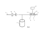
- the pressure tank device which in Fig. 2 is different from the pressure tank device of FIG Fig. 1 in that only the first magnetic coil 6 is used to actuate the shut-off valve 4.
- the current direction in the first solenoid 6 is reversed by the control unit 9.
- the invention thus provides a pressure tank device and a method for operating a pressure tank device, which prevent damage to the downstream consumers when refueling the pressure tank device.
Landscapes
- Engineering & Computer Science (AREA)
- Mechanical Engineering (AREA)
- General Engineering & Computer Science (AREA)
- Filling Or Discharging Of Gas Storage Vessels (AREA)
- Cooling, Air Intake And Gas Exhaust, And Fuel Tank Arrangements In Propulsion Units (AREA)
Abstract
Description
- Die vorliegende Erfindung betrifft eine Drucktankvorrichtung umfassend einen Drucktank, einen Hochdruckeingang zum Drucktank und einen Niederdruckausgang vom Drucktank und ein Verfahren zum Betreiben einer derartigen Drucktankvorrichtung. Derartige Drucktankvorrichtungen werden beispielsweise als Gashochdruckspeichersysteme zur Bereitstellung eines Kraftstoffes, wie Wasserstoff, zum Betrieb eines Kraftfahrzeuges verwendet.
- Derartige Drucktankvorrichtungen können über einen Hochdruckeingang betankt werden. Über einen Niederdruckausgang erfolgt die Entnahme des gespeicherten Mediums. Im Rahmen dieser Patentschrift wird unter dem Begriff "Hochdruckeingang" der gesamte Eingangsbereich zum Drucktank verstanden, in welchem zumindest abschnittsweise und bevorzugt überall ein hoher Druck herrscht und unter dem Begriff "Niederdruckausgang" der gesamte Ausgangsbereich vom Drucktank verstanden, in welchem zumindest abschnittsweise, nämlich stromabwärts beispielsweise eines Druckreglers, ein niedrigerer Druck herrscht. Dabei ist im Niederdruckausgang ein elektromechanisches Absperrventil mit einem Absperrventilverschlusskörper und einem Absperrventilsitz angeordnet, das dazu dient, das im Drucktank gespeicherte Medium einem Abnehmer bereitzustellen und in einem Ruhebetrieb der Drucktankvorrichtung, in welchem keine Entnahme des Mediums stattfindet, den Niederdruckausgang zu schlie-βen. Zusätzlich zum Absperrventil können Mengenregler und/oder Druckregler im Niederdruckausgang angeordnet sein. Derartige Absperrventile nutzen in der Regel den anliegenden Druck aus dem Drucktank um den Niederdruckausgang zu verschließen, solange kein Medium aus dem Drucktank entnommen wird. Wenn es zu einem starken Druckanstieg kommt, können die Absperrventile jedoch undicht sein.
- Insbesondere am Beginn eines Betankungsvorgangs derartiger Drucktanksysteme kommt es üblicherweise zu einem starken Druckanstieg sowohl im Hochdruckeingang als auch zu einem nicht erwünschten Druckanstieg im Niederdruckausgang. Ein kurzer Druckimpuls wird in der Regel am Beginn eines Betankungsvorgangs von einer Betankungsanlage abgesetzt um Eigenschaften wie die Dichtheit und das zur Verfügung stehende Tankvolumen des Drucktanks zu ermitteln. Durch diesen raschen Druckanstieg kann es zur oben erwähnten Undichtheit am Absperrventil und in weiterer Folge zu Beschädigungen am an den Niederdruckausgang angeschlossenen Abnehmer des gespeicherten Mediums kommen.
- Es ist eine Aufgabe der Erfindung, ein Verfahren zum Betreiben einer Drucktankvorrichtung der genannten Art und eine Drucktankvorrichtung anzugeben, die Schäden der Verbraucher beim Betanken der Drucktankvorrichtung verhindern.
- Die Lösung der Aufgabe erfolgt durch ein Verfahren zum Betreiben einer Drucktankvorrichtung umfassend einen Drucktank, einen Hochdruckeingang zum Drucktank und einen Niederdruckausgang vom Drucktank, wobei im Niederdruckausgang zumindest ein elektromechanisches Absperrventil mit einem Absperrventilverschlusskörper und einem Absperrventilsitz angeordnet ist, wobei zumindest am Beginn einer Betankung der Drucktankvorrichtung über den Hochdruckeingang, der Absperrventilverschlusskörper auf den Absperrventilsitz eine höhere Druckkraft aufbringt, als während einem Ruhebetrieb der Drucktankvorrichtung.
- Die Lösung der Aufgabe erfolgt auch durch eine Drucktankvorrichtung umfassend einen Drucktank, einen Hochdruckeingang zum Drucktank und einen Niederdruckausgang vom Drucktank, wobei im Niederdruckausgang zumindest ein elektromechanisches Absperrventil mit einem Absperrventilverschlusskörper und einem Absperrventilsitz angeordnet ist, wobei die Drucktankvorrichtung dazu eingerichtet ist, im Betrieb das oben genannte Verfahren auszuführen, so dass also zumindest am Beginn einer Betankung der Drucktankvorrichtung über den Hochdruckeingang, der Absperrventilverschlusskörper auf den Absperrventilsitz eine höhere Druckkraft aufbringt, als während einem Ruhebetrieb der Drucktankvorrichtung.
- Der Ruhebetrieb der Drucktankvorrichtung ist ein Betrieb der Drucktankvorrichtung in welchem keine Entnahme des im Drucktank gespeicherten Mediums erfolgt (Entnahmebetrieb) und keine Betankung des Drucktanks erfolgt.
- Üblicherweise ist im Ruhebetrieb einer Drucktankvorrichtung das Absperrventil geschlossen, der Absperrventilverschlusskörper sitzt daher auf dem Absperrventilsitz auf.
- Erfindungsgemäß ist vorgesehen, dass zumindest am Beginn einer Betankung der Drucktankvorrichtung der Absperrventilverschlusskörper auf den Absperrventilsitz eine höhere Druckkraft aufbringt, als während dem Ruhebetrieb der Drucktankvorrichtung. Hierdurch ist sicher gestellt dass eventuelle Druckimpulse am Beginn einer Betankung nicht zu einer Undichtheit am Absperrventil führen. Die erhöhte Druckkraft muss dabei aber energiesparend nur für kurze Zeit aufgebracht werden und nicht etwa während des gesamten Ruhebetriebs der Drucktankvorrichtung aufrecht gehalten werden.
- Gemäß einer Ausführungsform des erfindungsgemäßen Verfahrens kann der Absperrventilverschlusskörper auf den Absperrventilsitz während der gesamten Betankung der Drucktankvorrichtung über den Hochdruckeingang eine höhere Druckkraft aufbringen um die Dichtheit während der gesamten Betankungsdauer sicher zu stellen.
- Es kann auch vorgesehen sein, dass bei jedem vorgegebenen Druckanstieg am Hochdruckeingang, also nicht nur im Zuge einer Betankung, der Absperrventilverschlusskörper auf den Absperrventilsitz eine höhere Druckkraft aufbringt, als während dem Ruhebetrieb der Drucktankvorrichtung. So kann nach Detektion eines Druckanstieges in vorgegebener Höhe stets die Dichtheit am Absperrventil sicher gestellt werden.
- Bevorzugt wird das Absperrventil während einem Entnahmebetrieb, also während der Entnahme von gespeichertem Medium aus dem Drucktank für einen Verbraucher, durch eine erste Magnetspule in Öffnungsrichtung aktuiert.
- Gemäß einer Ausführungsform wird das Absperrventil, zum Aufbringen der höheren Druckkraft des Absperrventilverschlusskörpers auf den Absperrventilsitz, durch eine zweite Magnetspule in Schließrichtung aktuiert. Es ist also zusätzlich zu einer ersten Magnetspule, die die Öffnung des Absperrventils im Entnahmebetrieb bewirken kann, eine zweite Magnetspule vorgesehen, um eine hohe Schließkraft des Absperrventils insbesondere am Beginn einer Betankung zu erzeugen.
- Gemäß einer weiteren Ausführungsform wird das Absperrventil, zum Aufbringen der höheren Druckkraft des Absperrventilverschlusskörpers auf den Absperrventilsitz, durch die erste Magnetspule in Schließrichtung aktuiert. Die erhöhte Schließkraft des Absperrventils wird also durch die selbe Magnetspule bewirkt, die zur Öffnung des Absperrventils im Entnahmebetrieb genutzt wird. Dabei bewirkt die erste Magnetspule dass der Absperrventilverschlusskörper auf den Absperrventilsitz eine höhere Druckkraft aufbringt als während dem Ruhebetrieb. Im Ruhebetrieb kann das Absperrventil über die erste Magnetspule weniger stark aktuiert sein oder auch gar nicht.
- Bevorzugt wird das Absperrventil, zum Aufbringen der höheren Druckkraft des Absperrventilverschlusskörpers auf den Absperrventilsitz, durch eine Umkehr der Stromrichtung der ersten Magnetspule in Schließrichtung aktuiert, so dass das Absperrventil durch die erste Magnetspule geschlossen wird, anstatt geöffnet wie im Entnahmebetrieb. Hierdurch ist eine besonders einfache und kostengünstige Lösung zur Erhöhung der Druckkraft am Absperrventil gegeben.
- Bevorzugt kann die Stärke des Stromes in der ersten und/oder der zweiten Magnetspule einstellbar sein, insbesondere durch Pulsweitenmodulations-Ansteuerung der Magnetspule.
- Eine erfindungsgemäße Drucktankvorrichtung umfasst bevorzugt ein Steuergerät, wobei das Steuergerät dazu eingerichtet ist, die Drucktankvorrichtung gemäß einem der oben genannten Verfahren zu betreiben. Als Steuergerät kann erfindungsgemäß jede Vorrichtung eingesetzt werden die dazu in der Lage ist, die Drucktankvorrichtung nach einem der beschriebenen Verfahren zu betreiben. Dies kann ein Steuergerät sein das einen Mikroprozessor umfasst oder auch eine einfachere elektrische Vorrichtung, beispielsweise umfassend Sensoren und Schalter. Auch könnte die Drucktankvorrichtung mechanisch betrieben sein.
- Die Drucktankvorrichtung kann zur Ausführung eines erfindungsgemä-βen Verfahrens beispielsweise eine erste Magnetspule umfassen, durch welche das Absperrventil während einem Entnahmebetrieb in Öffnungsrichtung aktuiert wird und zusätzlich eine zweite Magnetspule zum Aufbringen der höheren Druckkraft des Absperrventilverschlusskörpers auf den Absperrventilsitz zumindest am Beginn einer Betankung. Alternativ zur zweiten Magnetspule kann die Drucktankvorrichtung auch ein Mittel, insbesondere eine Schaltung umfassen, durch welche das Absperrventil, zum Aufbringen der höheren Druckkraft des Absperrventilverschlusskörpers auf den Absperrventilsitz, durch eine Umkehr der Stromrichtung der ersten Magnetspule in Schließrichtung aktuiert wird.
- Eine erfindungsgemäße Drucktankvorrichtung kann beispielsweise in einem Kraft-, Luft-, Wasser- oder Schienenfahrzeug sowie auch in stationären Anlagen eingesetzt werden.
- Weiterbildungen der Erfindung sind in den abhängigen Ansprüchen, der Beschreibung sowie den beigefügten Zeichnungen angegeben.
- Die Erfindung wird im Folgenden beispielhaft unter Bezugnahme auf die Zeichnungen beschrieben.
- Fig. 1
- ist eine schematische Darstellung einer erfindungsgemäßen Drucktankvorrichtung.
- Fig. 2
- ist eine schematische Darstellung einer weiteren erfindungsgemäßen Drucktankvorrichtung.
- In
Fig. 1 ist eine erfindungsgemäße Drucktankvorrichtung dargestellt, mit einem Drucktank 1, der über einen Hochdruckeingang 2, der ein Filter 11 und ein Rückschlagventil 8 umfassen kann, betankbar ist und mit einem Niederdruckausgang 3 zur Entnahme eines im Drucktank 1 gespeicherten Gases für einen Verbraucher. Im Niederdruckausgang 3 sind als Entnahmekomponenten ein Absperrventil 4 und ein Mengen- und / oder Druckregler 5 angeordnet. - Das Absperrventil 4 ist über eine erste Magnetspule 6 derart aktuierbar, dass das Absperrventil 4 in einem Entnahmebetrieb der Drucktankvorrichtung offen ist. In einem Ruhebetrieb ist das Absperrventil 4 geschlossen, beispielsweise durch eine stromlose Vorrichtung zur Schließung des Absperrventils wie eine Federbelastung. Durch eine zweite Magnetspule 7 kann das Absperrventil 4 während dem Beginn einer Betankung über den Hochdruckeingang 2 geschlossen werden, so dass der Absperrventilverschlusskörper des Absperrventils 4 auf den zugehörigen Absperrventilsitz eine höhere Druckkraft aufbringt, als während dem Ruhebetrieb der Drucktankvorrichtung.
- Ein Mengen- und / oder Druckregler 5 im Niederdruckausgang 3 kann über eine dritte Magnetspule 10 aktuierbar sein. Alle Magnetspulen 6, 7, 10 werden über ein Steuergerät 9 angesteuert.
- Die Drucktankvorrichtung, die in
Fig. 2 dargestellt ist, unterscheidet sich von der Drucktankvorrichtung derFig. 1 dadurch, dass zur Aktuierung des Absperrventils 4 lediglich die erste Magnetspule 6 verwendet wird. Zur Erreichung einer starken Druckkraft des Absperrventilverschlusskörpers auf den Absperrventilsitz wird die Stromrichtung in der ersten Magnetspule 6 durch das Steuergerät 9 umgekehrt. - Die Erfindung gibt somit eine Drucktankvorrichtung und ein Verfahren zum Betrieb einer Drucktankvorrichtung an, die Schäden der nachgeschalteten Verbraucher beim Betanken der Drucktankvorrichtung verhindern.
Bezugszeichenliste 1 Drucktank 2 Hochdruckeingang 3 Niederdruckausgang 4 Absperrventil 5 Mengen- und / oder Druckregler 6 erste Magnetspule 7 zweite Magnetspule 8 Rückschlagventil 9 Steuergerät 10 dritte Magnetspule 11 Filter
Claims (12)
- Verfahren zum Betreiben einer Drucktankvorrichtung umfassend einen Drucktank (1), einen Hochdruckeingang (2) zum Drucktank (1) und einen Niederdruckausgang (3) vom Drucktank (1), wobei im Niederdruckausgang (3) zumindest ein elektromechanisches Absperrventil (4) mit einem Absperrventilverschlusskörper und einem Absperrventilsitz angeordnet ist,
dadurch gekennzeichnet, dass, zumindest am Beginn einer Betankung der Drucktankvorrichtung über den Hochdruckeingang (2), der Absperrventilverschlusskörper auf den Absperrventilsitz eine höhere Druckkraft aufbringt, als während einem Ruhebetrieb der Drucktankvorrichtung. - Verfahren nach Anspruch 1,
dadurch gekennzeichnet, dass während der gesamten Betankung der Drucktankvorrichtung über den Hochdruckeingang (2), der Absperrventilverschlusskörper auf den Absperrventilsitz eine höhere Druckkraft aufbringt, als während einem Ruhebetrieb der Drucktankvorrichtung. - Verfahren nach Anspruch 1 oder 2,
dadurch gekennzeichnet, dass bei jedem vorgegebenen Druckanstieg am Hochdruckeingang (2), der Absperrventilverschlusskörper auf den Absperrventilsitz eine höhere Druckkraft aufbringt, als während einem Ruhebetrieb der Drucktankvorrichtung. - Verfahren nach zumindest einem der zuvor genannten Ansprüche, dadurch gekennzeichnet, dass das absperrventil (4) während einem Entnahmebetrieb durch eine erste Magnetspule (6) in Öffnungsrichtung aktuiert wird.
- Verfahren nach zumindest einem der zuvor genannten Ansprüche, dadurch gekennzeichnet, dass das absperrventil (4), zum Aufbringen der höheren Druckkraft des Absperrventilverschlusskörpers auf den Absperrventilsitz, durch eine zweite Magnetspule (7) in Schließrichtung aktuiert wird.
- Verfahren nach zumindest einem der Ansprüche 1 bis 4,
dadurch gekennzeichnet, dass das absperrventil (4), zum Aufbringen der höheren Druckkraft des Absperrventilverschlusskörpers auf den Absperrventilsitz, durch die erste Magnetspule (6) in Schließrichtung aktuiert wird. - Verfahren nach Anspruch 6,
dadurch gekennzeichnet, dass das absperrventil (4), zum Aufbringen der höheren Druckkraft des Absperrventilverschlusskörpers auf den Absperrventilsitz, durch eine Umkehr der Stromrichtung der ersten Magnetspule (6) in Schließrichtung aktuiert wird. - Verfahren zumindest einem der zuvor genannten Ansprüche,
dadurch gekennzeichnet, dass die Stärke des Stromes in der ersten und/oder zweiten Magnetspule (6, 7) einstellbar ist, insbesondere durch Pulsweitenmodulations-Ansteuerung der Magnetspule. - Drucktankvorrichtung umfassend einen Drucktank (1), einen Hochdruckeingang (2) zum Drucktank (1) und einen Niederdruckausgang (3) vom Drucktank (1), wobei im Niederdruckausgang (3) zumindest ein elektromechanisches Absperrventil (4) mit einem Absperrventilverschlusskörper und einem Absperrventilsitz angeordnet ist, dadurch gekennzeichnet, dass die Drucktankvorrichtung dazu eingerichtet ist, im Betrieb ein Verfahren nach zumindest einem der Ansprüche 1 bis 8 auszuführen.
- Drucktankvorrichtung nach Anspruch 9, wobei die Drucktankvorrichtung ein Steuergerät (9) umfasst,
dadurch gekennzeichnet, dass das Steuergerät (9) dazu eingerichtet ist, die Drucktankvorrichtung gemäß einem Verfahren nach zumindest einem der Ansprüche 1 bis 8 zu betreiben. - Drucktankvorrichtung nach Anspruch 9 oder 10,
dadurch gekennzeichnet, dass die Drucktankvorrichtung eine erste Magnetspule (6) umfasst, durch welche das Absperrventil (4) während einem Entnahmebetrieb durch eine erste Magnetspule (6) in Öffnungsrichtung aktuiert wird und eine zweite Magnetspule (7) zum Aufbringen der höheren Druckkraft des Absperrventilverschlusskörpers auf den Absperrventilsitz zumindest am Beginn einer Betankung. - Drucktankvorrichtung nach Anspruch 9 oder 10,
dadurch gekennzeichnet, dass die Drucktankvorrichtung eine erste Magnetspule (6) umfasst, durch welche das Absperrventil (4) während einem Entnahmebetrieb durch eine erste Magnetspule (6) in Öffnungsrichtung aktuiert wird und ein Mittel, durch welches das Absperrventil (4), zum Aufbringen der höheren Druckkraft des Absperrventilverschlusskörpers auf den Absperrventilsitz, durch eine Umkehr der Stromrichtung der ersten Magnetspule (6) in Schließrichtung aktuiert wird.
Priority Applications (1)
| Application Number | Priority Date | Filing Date | Title |
|---|---|---|---|
| EP13159212.3A EP2778500B1 (de) | 2013-03-14 | 2013-03-14 | Verfahren zum Betreiben einer Drucktankvorrichtung und Drucktankvorrichtung |
Applications Claiming Priority (1)
| Application Number | Priority Date | Filing Date | Title |
|---|---|---|---|
| EP13159212.3A EP2778500B1 (de) | 2013-03-14 | 2013-03-14 | Verfahren zum Betreiben einer Drucktankvorrichtung und Drucktankvorrichtung |
Publications (2)
| Publication Number | Publication Date |
|---|---|
| EP2778500A1 true EP2778500A1 (de) | 2014-09-17 |
| EP2778500B1 EP2778500B1 (de) | 2021-07-07 |
Family
ID=47900804
Family Applications (1)
| Application Number | Title | Priority Date | Filing Date |
|---|---|---|---|
| EP13159212.3A Active EP2778500B1 (de) | 2013-03-14 | 2013-03-14 | Verfahren zum Betreiben einer Drucktankvorrichtung und Drucktankvorrichtung |
Country Status (1)
| Country | Link |
|---|---|
| EP (1) | EP2778500B1 (de) |
Cited By (2)
| Publication number | Priority date | Publication date | Assignee | Title |
|---|---|---|---|---|
| EP3002497A1 (de) * | 2014-09-30 | 2016-04-06 | Air Products And Chemicals, Inc. | Reduzierung von Druckspitzen während der Abgabe von Wasserstoff |
| US9404620B2 (en) | 2014-09-30 | 2016-08-02 | Air Products And Chemicals, Inc. | Reducing pressure spikes during hydrogen dispensing |
Citations (2)
| Publication number | Priority date | Publication date | Assignee | Title |
|---|---|---|---|---|
| EP1722152A2 (de) * | 2005-05-09 | 2006-11-15 | Honda Motor Co., Ltd. | Druckbetriebenes Kühlsystem zur Steigerung der Nachfüllungsgeschwindigkeit und der Kapazität von Hochdruckgasbehältern in Kraftfahrzeugen |
| WO2009063282A1 (en) * | 2007-04-02 | 2009-05-22 | Honda Motor Co., Ltd. | Supplemental heat exchange for high pressure gas tank |
-
2013
- 2013-03-14 EP EP13159212.3A patent/EP2778500B1/de active Active
Patent Citations (2)
| Publication number | Priority date | Publication date | Assignee | Title |
|---|---|---|---|---|
| EP1722152A2 (de) * | 2005-05-09 | 2006-11-15 | Honda Motor Co., Ltd. | Druckbetriebenes Kühlsystem zur Steigerung der Nachfüllungsgeschwindigkeit und der Kapazität von Hochdruckgasbehältern in Kraftfahrzeugen |
| WO2009063282A1 (en) * | 2007-04-02 | 2009-05-22 | Honda Motor Co., Ltd. | Supplemental heat exchange for high pressure gas tank |
Cited By (2)
| Publication number | Priority date | Publication date | Assignee | Title |
|---|---|---|---|---|
| EP3002497A1 (de) * | 2014-09-30 | 2016-04-06 | Air Products And Chemicals, Inc. | Reduzierung von Druckspitzen während der Abgabe von Wasserstoff |
| US9404620B2 (en) | 2014-09-30 | 2016-08-02 | Air Products And Chemicals, Inc. | Reducing pressure spikes during hydrogen dispensing |
Also Published As
| Publication number | Publication date |
|---|---|
| EP2778500B1 (de) | 2021-07-07 |
Similar Documents
| Publication | Publication Date | Title |
|---|---|---|
| DE102012206810B4 (de) | System und verfahren zum diagnostizieren eines ventillecks in einem fahrzeug | |
| WO2020120072A1 (de) | Verfahren zum betreiben einer tankvorrichtung zur speicherung von verdichteten fluiden | |
| DE102009049687A1 (de) | Gasbehälteranordnung und Verfahren zum Betreiben einer Gasbehälteranordnung | |
| DE102006017541B4 (de) | Verfahren zum Austrag von Hochdruckspeicherbehältern | |
| WO2021228508A1 (de) | Steuereinheit und verfahren zum betrieb eines druckbehälter-ventils eines druckbehälters | |
| DE102018215380A1 (de) | Ventilvorrichtung für ein gasförmiges Medium und Tankvorrichtung zur Speicherung eines gasförmigen Mediums | |
| DE102008000983A1 (de) | Verfahren und Vorrichtung zur Steuerung eines Kraftstoffzumesssystems | |
| WO2017198379A1 (de) | Absperrventil, scr-system und verfahren zur leckagedetektion und/oder dosiermengenabweichungserkennung | |
| DE102014206717B4 (de) | Druckspeichereinrichtung für ein Kraftfahrzeug-Kraftstoff-Einspritzsystem, sowie Verfahren zum Betrieb einer derartigen Druckspeichereinrichtung | |
| AT522522B1 (de) | Brennstoffzellensystem und Verfahren zum Entfernen von Wasser aus dem Brennstoffzellensystem | |
| DE102008029224A1 (de) | Verfahren zum Überprüfen der Funktion eines in einer Fluid-Leitung in einem Kraftfahrzeug angeordneten Absperrventils | |
| DE102019131406A1 (de) | Verfahren und Vorrichtung zur Ermittlung des Zustands eines Magnet-Schaltelements | |
| EP2778500B1 (de) | Verfahren zum Betreiben einer Drucktankvorrichtung und Drucktankvorrichtung | |
| EP2069155B1 (de) | Verfahren zur steuerung und/oder regelung des niveaus eines fahrzeugaufbaus eines kraftfahrzeuges | |
| DE102004037255B4 (de) | Verfahren zum Betreiben einer Kraftstoffeinspritzvorrichtung insbesondere für ein Kraftfahrzeug | |
| DE102012218856A1 (de) | Kraftstoffspeicheranlage eines Kraftfahrzeugs | |
| WO2024104679A1 (de) | Verfahren zum betreiben eines brenngastanksystems, steuergerät | |
| EP2777969B1 (de) | Drucktankvorrichtung | |
| DE102006043607A1 (de) | Verfahren zur Diagnose der Funktion einer Niveauregelanlage eines Kraftfahrzeugs | |
| DE102008002019A1 (de) | Verfahren und Vorrichtung zur Ansteuerung eines Magnetventils | |
| EP3252299A1 (de) | Kraftstoffdruckspeicher, einspritzsystem mit einem kraftstoffdruckspeicher und verfahren zum betreiben eines einspritzsystems mit einem kraftstoffdruckspeicher | |
| EP3234328B1 (de) | Verfahren und vorrichtung zur diagnose eines kraftstofffördersystems | |
| DE102013219396A1 (de) | Verfahren zum Erkennen eines unerwünschten Schließens eines elektrischen Saugventils einer Hochdruckpumpe | |
| DE102014210242B4 (de) | Drucktankanordnung | |
| DE102008031343A1 (de) | Verfahren zum Überwachen eines Boil-Off-Ventils eines Kryotanks eines Kraftfahrzeugs |
Legal Events
| Date | Code | Title | Description |
|---|---|---|---|
| PUAI | Public reference made under article 153(3) epc to a published international application that has entered the european phase |
Free format text: ORIGINAL CODE: 0009012 |
|
| 17P | Request for examination filed |
Effective date: 20130314 |
|
| AK | Designated contracting states |
Kind code of ref document: A1 Designated state(s): AL AT BE BG CH CY CZ DE DK EE ES FI FR GB GR HR HU IE IS IT LI LT LU LV MC MK MT NL NO PL PT RO RS SE SI SK SM TR |
|
| AX | Request for extension of the european patent |
Extension state: BA ME |
|
| R17P | Request for examination filed (corrected) |
Effective date: 20150211 |
|
| RBV | Designated contracting states (corrected) |
Designated state(s): AL AT BE BG CH CY CZ DE DK EE ES FI FR GB GR HR HU IE IS IT LI LT LU LV MC MK MT NL NO PL PT RO RS SE SI SK SM TR |
|
| STAA | Information on the status of an ep patent application or granted ep patent |
Free format text: STATUS: EXAMINATION IS IN PROGRESS |
|
| 17Q | First examination report despatched |
Effective date: 20170410 |
|
| GRAP | Despatch of communication of intention to grant a patent |
Free format text: ORIGINAL CODE: EPIDOSNIGR1 |
|
| STAA | Information on the status of an ep patent application or granted ep patent |
Free format text: STATUS: GRANT OF PATENT IS INTENDED |
|
| INTG | Intention to grant announced |
Effective date: 20210406 |
|
| GRAS | Grant fee paid |
Free format text: ORIGINAL CODE: EPIDOSNIGR3 |
|
| GRAA | (expected) grant |
Free format text: ORIGINAL CODE: 0009210 |
|
| STAA | Information on the status of an ep patent application or granted ep patent |
Free format text: STATUS: THE PATENT HAS BEEN GRANTED |
|
| AK | Designated contracting states |
Kind code of ref document: B1 Designated state(s): AL AT BE BG CH CY CZ DE DK EE ES FI FR GB GR HR HU IE IS IT LI LT LU LV MC MK MT NL NO PL PT RO RS SE SI SK SM TR |
|
| REG | Reference to a national code |
Ref country code: GB Ref legal event code: FG4D Free format text: NOT ENGLISH |
|
| REG | Reference to a national code |
Ref country code: AT Ref legal event code: REF Ref document number: 1408932 Country of ref document: AT Kind code of ref document: T Effective date: 20210715 |
|
| REG | Reference to a national code |
Ref country code: DE Ref legal event code: R096 Ref document number: 502013015814 Country of ref document: DE |
|
| REG | Reference to a national code |
Ref country code: IE Ref legal event code: FG4D Free format text: LANGUAGE OF EP DOCUMENT: GERMAN |
|
| REG | Reference to a national code |
Ref country code: LT Ref legal event code: MG9D |
|
| REG | Reference to a national code |
Ref country code: NL Ref legal event code: MP Effective date: 20210707 |
|
| PG25 | Lapsed in a contracting state [announced via postgrant information from national office to epo] |
Ref country code: BG Free format text: LAPSE BECAUSE OF FAILURE TO SUBMIT A TRANSLATION OF THE DESCRIPTION OR TO PAY THE FEE WITHIN THE PRESCRIBED TIME-LIMIT Effective date: 20211007 Ref country code: LT Free format text: LAPSE BECAUSE OF FAILURE TO SUBMIT A TRANSLATION OF THE DESCRIPTION OR TO PAY THE FEE WITHIN THE PRESCRIBED TIME-LIMIT Effective date: 20210707 Ref country code: ES Free format text: LAPSE BECAUSE OF FAILURE TO SUBMIT A TRANSLATION OF THE DESCRIPTION OR TO PAY THE FEE WITHIN THE PRESCRIBED TIME-LIMIT Effective date: 20210707 Ref country code: FI Free format text: LAPSE BECAUSE OF FAILURE TO SUBMIT A TRANSLATION OF THE DESCRIPTION OR TO PAY THE FEE WITHIN THE PRESCRIBED TIME-LIMIT Effective date: 20210707 Ref country code: NL Free format text: LAPSE BECAUSE OF FAILURE TO SUBMIT A TRANSLATION OF THE DESCRIPTION OR TO PAY THE FEE WITHIN THE PRESCRIBED TIME-LIMIT Effective date: 20210707 Ref country code: PT Free format text: LAPSE BECAUSE OF FAILURE TO SUBMIT A TRANSLATION OF THE DESCRIPTION OR TO PAY THE FEE WITHIN THE PRESCRIBED TIME-LIMIT Effective date: 20211108 Ref country code: NO Free format text: LAPSE BECAUSE OF FAILURE TO SUBMIT A TRANSLATION OF THE DESCRIPTION OR TO PAY THE FEE WITHIN THE PRESCRIBED TIME-LIMIT Effective date: 20211007 Ref country code: RS Free format text: LAPSE BECAUSE OF FAILURE TO SUBMIT A TRANSLATION OF THE DESCRIPTION OR TO PAY THE FEE WITHIN THE PRESCRIBED TIME-LIMIT Effective date: 20210707 Ref country code: HR Free format text: LAPSE BECAUSE OF FAILURE TO SUBMIT A TRANSLATION OF THE DESCRIPTION OR TO PAY THE FEE WITHIN THE PRESCRIBED TIME-LIMIT Effective date: 20210707 Ref country code: SE Free format text: LAPSE BECAUSE OF FAILURE TO SUBMIT A TRANSLATION OF THE DESCRIPTION OR TO PAY THE FEE WITHIN THE PRESCRIBED TIME-LIMIT Effective date: 20210707 |
|
| PG25 | Lapsed in a contracting state [announced via postgrant information from national office to epo] |
Ref country code: PL Free format text: LAPSE BECAUSE OF FAILURE TO SUBMIT A TRANSLATION OF THE DESCRIPTION OR TO PAY THE FEE WITHIN THE PRESCRIBED TIME-LIMIT Effective date: 20210707 Ref country code: LV Free format text: LAPSE BECAUSE OF FAILURE TO SUBMIT A TRANSLATION OF THE DESCRIPTION OR TO PAY THE FEE WITHIN THE PRESCRIBED TIME-LIMIT Effective date: 20210707 Ref country code: GR Free format text: LAPSE BECAUSE OF FAILURE TO SUBMIT A TRANSLATION OF THE DESCRIPTION OR TO PAY THE FEE WITHIN THE PRESCRIBED TIME-LIMIT Effective date: 20211008 |
|
| REG | Reference to a national code |
Ref country code: DE Ref legal event code: R097 Ref document number: 502013015814 Country of ref document: DE |
|
| PG25 | Lapsed in a contracting state [announced via postgrant information from national office to epo] |
Ref country code: DK Free format text: LAPSE BECAUSE OF FAILURE TO SUBMIT A TRANSLATION OF THE DESCRIPTION OR TO PAY THE FEE WITHIN THE PRESCRIBED TIME-LIMIT Effective date: 20210707 |
|
| PLBE | No opposition filed within time limit |
Free format text: ORIGINAL CODE: 0009261 |
|
| STAA | Information on the status of an ep patent application or granted ep patent |
Free format text: STATUS: NO OPPOSITION FILED WITHIN TIME LIMIT |
|
| PG25 | Lapsed in a contracting state [announced via postgrant information from national office to epo] |
Ref country code: SM Free format text: LAPSE BECAUSE OF FAILURE TO SUBMIT A TRANSLATION OF THE DESCRIPTION OR TO PAY THE FEE WITHIN THE PRESCRIBED TIME-LIMIT Effective date: 20210707 Ref country code: SK Free format text: LAPSE BECAUSE OF FAILURE TO SUBMIT A TRANSLATION OF THE DESCRIPTION OR TO PAY THE FEE WITHIN THE PRESCRIBED TIME-LIMIT Effective date: 20210707 Ref country code: RO Free format text: LAPSE BECAUSE OF FAILURE TO SUBMIT A TRANSLATION OF THE DESCRIPTION OR TO PAY THE FEE WITHIN THE PRESCRIBED TIME-LIMIT Effective date: 20210707 Ref country code: EE Free format text: LAPSE BECAUSE OF FAILURE TO SUBMIT A TRANSLATION OF THE DESCRIPTION OR TO PAY THE FEE WITHIN THE PRESCRIBED TIME-LIMIT Effective date: 20210707 Ref country code: CZ Free format text: LAPSE BECAUSE OF FAILURE TO SUBMIT A TRANSLATION OF THE DESCRIPTION OR TO PAY THE FEE WITHIN THE PRESCRIBED TIME-LIMIT Effective date: 20210707 Ref country code: AL Free format text: LAPSE BECAUSE OF FAILURE TO SUBMIT A TRANSLATION OF THE DESCRIPTION OR TO PAY THE FEE WITHIN THE PRESCRIBED TIME-LIMIT Effective date: 20210707 |
|
| 26N | No opposition filed |
Effective date: 20220408 |
|
| PG25 | Lapsed in a contracting state [announced via postgrant information from national office to epo] |
Ref country code: IT Free format text: LAPSE BECAUSE OF FAILURE TO SUBMIT A TRANSLATION OF THE DESCRIPTION OR TO PAY THE FEE WITHIN THE PRESCRIBED TIME-LIMIT Effective date: 20210707 |
|
| REG | Reference to a national code |
Ref country code: DE Ref legal event code: R081 Ref document number: 502013015814 Country of ref document: DE Owner name: MAGNA STEYR FAHRZEUGTECHNIK GMBH & CO KG, AT Free format text: FORMER OWNER: MAGNA STEYR FAHRZEUGTECHNIK AG & CO KG, GRAZ, AT |
|
| PG25 | Lapsed in a contracting state [announced via postgrant information from national office to epo] |
Ref country code: MC Free format text: LAPSE BECAUSE OF FAILURE TO SUBMIT A TRANSLATION OF THE DESCRIPTION OR TO PAY THE FEE WITHIN THE PRESCRIBED TIME-LIMIT Effective date: 20210707 |
|
| REG | Reference to a national code |
Ref country code: CH Ref legal event code: PL |
|
| GBPC | Gb: european patent ceased through non-payment of renewal fee |
Effective date: 20220314 |
|
| REG | Reference to a national code |
Ref country code: BE Ref legal event code: MM Effective date: 20220331 |
|
| PG25 | Lapsed in a contracting state [announced via postgrant information from national office to epo] |
Ref country code: LU Free format text: LAPSE BECAUSE OF NON-PAYMENT OF DUE FEES Effective date: 20220314 Ref country code: LI Free format text: LAPSE BECAUSE OF NON-PAYMENT OF DUE FEES Effective date: 20220331 Ref country code: IE Free format text: LAPSE BECAUSE OF NON-PAYMENT OF DUE FEES Effective date: 20220314 Ref country code: GB Free format text: LAPSE BECAUSE OF NON-PAYMENT OF DUE FEES Effective date: 20220314 Ref country code: FR Free format text: LAPSE BECAUSE OF NON-PAYMENT OF DUE FEES Effective date: 20220331 Ref country code: CH Free format text: LAPSE BECAUSE OF NON-PAYMENT OF DUE FEES Effective date: 20220331 |
|
| PG25 | Lapsed in a contracting state [announced via postgrant information from national office to epo] |
Ref country code: BE Free format text: LAPSE BECAUSE OF NON-PAYMENT OF DUE FEES Effective date: 20220331 |
|
| REG | Reference to a national code |
Ref country code: AT Ref legal event code: MM01 Ref document number: 1408932 Country of ref document: AT Kind code of ref document: T Effective date: 20220314 |
|
| PG25 | Lapsed in a contracting state [announced via postgrant information from national office to epo] |
Ref country code: AT Free format text: LAPSE BECAUSE OF NON-PAYMENT OF DUE FEES Effective date: 20220314 |
|
| PG25 | Lapsed in a contracting state [announced via postgrant information from national office to epo] |
Ref country code: HU Free format text: LAPSE BECAUSE OF FAILURE TO SUBMIT A TRANSLATION OF THE DESCRIPTION OR TO PAY THE FEE WITHIN THE PRESCRIBED TIME-LIMIT; INVALID AB INITIO Effective date: 20130314 |
|
| PG25 | Lapsed in a contracting state [announced via postgrant information from national office to epo] |
Ref country code: MK Free format text: LAPSE BECAUSE OF FAILURE TO SUBMIT A TRANSLATION OF THE DESCRIPTION OR TO PAY THE FEE WITHIN THE PRESCRIBED TIME-LIMIT Effective date: 20210707 Ref country code: CY Free format text: LAPSE BECAUSE OF FAILURE TO SUBMIT A TRANSLATION OF THE DESCRIPTION OR TO PAY THE FEE WITHIN THE PRESCRIBED TIME-LIMIT Effective date: 20210707 |
|
| PG25 | Lapsed in a contracting state [announced via postgrant information from national office to epo] |
Ref country code: TR Free format text: LAPSE BECAUSE OF FAILURE TO SUBMIT A TRANSLATION OF THE DESCRIPTION OR TO PAY THE FEE WITHIN THE PRESCRIBED TIME-LIMIT Effective date: 20210707 |
|
| PG25 | Lapsed in a contracting state [announced via postgrant information from national office to epo] |
Ref country code: MT Free format text: LAPSE BECAUSE OF FAILURE TO SUBMIT A TRANSLATION OF THE DESCRIPTION OR TO PAY THE FEE WITHIN THE PRESCRIBED TIME-LIMIT Effective date: 20210707 |
|
| REG | Reference to a national code |
Ref country code: DE Ref legal event code: R082 Ref document number: 502013015814 Country of ref document: DE Representative=s name: EULER, MATTHIAS, DR., DE |
|
| PGFP | Annual fee paid to national office [announced via postgrant information from national office to epo] |
Ref country code: DE Payment date: 20260319 Year of fee payment: 14 |