EP2778438A1 - Dispositif d'obturation d'un système hydraulique, système hydraulique et aéronef - Google Patents
Dispositif d'obturation d'un système hydraulique, système hydraulique et aéronef Download PDFInfo
- Publication number
- EP2778438A1 EP2778438A1 EP14000414.4A EP14000414A EP2778438A1 EP 2778438 A1 EP2778438 A1 EP 2778438A1 EP 14000414 A EP14000414 A EP 14000414A EP 2778438 A1 EP2778438 A1 EP 2778438A1
- Authority
- EP
- European Patent Office
- Prior art keywords
- hydraulic system
- peripheral portion
- central portion
- closure device
- ring
- Prior art date
- Legal status (The legal status is an assumption and is not a legal conclusion. Google has not performed a legal analysis and makes no representation as to the accuracy of the status listed.)
- Granted
Links
Images

Classifications
-
- F—MECHANICAL ENGINEERING; LIGHTING; HEATING; WEAPONS; BLASTING
- F15—FLUID-PRESSURE ACTUATORS; HYDRAULICS OR PNEUMATICS IN GENERAL
- F15B—SYSTEMS ACTING BY MEANS OF FLUIDS IN GENERAL; FLUID-PRESSURE ACTUATORS, e.g. SERVOMOTORS; DETAILS OF FLUID-PRESSURE SYSTEMS, NOT OTHERWISE PROVIDED FOR
- F15B15/00—Fluid-actuated devices for displacing a member from one position to another; Gearing associated therewith
- F15B15/08—Characterised by the construction of the motor unit
- F15B15/14—Characterised by the construction of the motor unit of the straight-cylinder type
- F15B15/1423—Component parts; Constructional details
- F15B15/1438—Cylinder to end cap assemblies
-
- F—MECHANICAL ENGINEERING; LIGHTING; HEATING; WEAPONS; BLASTING
- F16—ENGINEERING ELEMENTS AND UNITS; GENERAL MEASURES FOR PRODUCING AND MAINTAINING EFFECTIVE FUNCTIONING OF MACHINES OR INSTALLATIONS; THERMAL INSULATION IN GENERAL
- F16L—PIPES; JOINTS OR FITTINGS FOR PIPES; SUPPORTS FOR PIPES, CABLES OR PROTECTIVE TUBING; MEANS FOR THERMAL INSULATION IN GENERAL
- F16L55/00—Devices or appurtenances for use in, or in connection with, pipes or pipe systems
- F16L55/10—Means for stopping flow in pipes or hoses
- F16L55/11—Plugs
Definitions
- the present invention relates to a closure device of a hydraulic system, such a hydraulic system and an aircraft comprising this hydraulic system. More particularly, the invention relates to an aircraft servocontrol.
- the servocontrols are notably used in the aeronautical field for the control of aerodynamic organs.
- servocontrols are implemented on a helicopter to control the pitch of the blades of the lift and propulsion rotor.
- a pilot can then transmit an order to the servocontrols via flight controls, the servocontrols acting on the pitch of the blades according to the orders received.
- the servo controls can be hydraulic servo controls.
- the flight controls then act on a hydraulic distributor which controls the delivery of a fluid to at least one body of the servocontrol.
- a hydraulic servocontrol comprises a hydraulic circuit.
- a servocontrol is usually provided with a closure device of this hydraulic circuit.
- a closure device comprises a plug for sealing an orifice of the hydraulic circuit.
- the plug is shaped to the orifice, being for example of cylindrical shape.
- An annular seal is disposed in a groove of the plug to seal between this plug and the wall defining the orifice.
- the closure device comprises a flange secured to the plug.
- the shutter device can be maintained against the servo control by screws fixing the collar to this body.
- a brake wire can be used to brake each screw.
- the closure device comprises a threaded portion extending the plug.
- the threaded portion then cooperates with a tapping of the body.
- a brake wire is then used to connect the threaded portion to the body.
- the plug may have a frustoconical shape of dimensions slightly greater than the dimensions of the orifice to be closed.
- the stopper is then forcefully inserted into the orifice according to the mounting technique known as "tight fitting".
- Such a plug is sometimes called "plug" in English.
- This type of assembly is used to seal small diameter orifices.
- the disassembly of the cap is delicate.
- the document GB 1584939 has a ring screwed to a housing.
- the document EP 2,243,976 has a ring wedged between a housing and a plug.
- the present invention therefore aims to provide an alternative closure device to allow a simple assembly and / or inexpensive.
- the invention thus proposes a device for closing off a hydraulic system, this closure device comprising a plug.
- the plug has a central portion cooperating with a peripheral portion surrounding this central portion, the closure device including an open stop elastic ring adapted to be inserted into a bore of the hydraulic system.
- the central portion protrudes from the peripheral portion towards the outside of the hydraulic system to provide a groove visible from the outside, the elastic locking ring being housed in this groove and able to be housed in the bore, the peripheral portion abutting axially against the elastic ring and the central portion radially locking the elastic ring when the closure device is correctly positioned.
- a resilient stop ring is an open ring for axially locking an object.
- Such an elastic stop ring is conventionally referred to as "circlip".
- Such a ring may be flat, unlike a retaining ring screwed to a housing for example.
- the elastic ring must be in the groove formed by the closure device, being arranged against a contact surface of the peripheral portion of the plug.
- the establishment of the closure device is easy, not requiring the arrangement of a particular brake (brake wire %) or a tight fitting for example. Maintaining the device shutter is guaranteed by the axial locking of the elastic ring in the bore.
- an operator can visually ensure the correct installation of the closure device. Indeed, if the elastic ring is not correctly pressed against the peripheral portion, this operator deduces that the closure device is not properly arranged.
- elastic stop rings are used in industry generally, but are little or not used in the aeronautical field. The use of such a ring in the frame for example of an aircraft servocontrol is then not obvious.
- the invention therefore tends to remove prejudices that have tarnished the image of elastic stop rings in the aeronautical field, to almost prevent their use in this particular technical field.
- the invention therefore proposes a simple shutter device that breaks the usual preconceived ideas, this closure device being associated with a simple and inexpensive mounting method.
- This shutter device may include one or more of the following additional features.
- a fluid may possibly partially leak while passing between the cap and the hydraulic system.
- the shutter device is not completely waterproof. Such a leak can possibly be mastered and drained for example.
- the closure device may comprise a peripheral seal to ensure a seal between the cap and the hydraulic system.
- a peripheral seal is for example arranged between the peripheral portion and the inner wall defining the cavity to be closed.
- the central portion and the peripheral portion are integral with each other, the peripheral portion representing at least one shoulder of the central portion.
- the cap is for example made in one piece so as to have on the one hand the central portion and on the other hand, the peripheral portion.
- This peripheral portion may comprise an upper shoulder and a lower shoulder of the central portion which are separated by an annular housing.
- a peripheral seal can then be arranged in this annular housing to ensure a seal between the cap and the hydraulic system.
- the upper shoulder is then in contact with the ring elastic stop when the shutter is correctly positioned.
- the central portion slides in the peripheral portion.
- the central portion comprises a rod of the hydraulic system, such as a rod carrying a piston.
- the central portion of the plug is therefore a movable functional element of the hydraulic system.
- the closure device comprises an internal seal interposed between the central portion and the peripheral portion. Nevertheless, it is possible not to implement such an internal seal, tolerating a possible controlled and drained leak.
- the closure device comprises a stop formed in the hydraulic system, the peripheral portion being in contact against the abutment and the elastic stop ring in normal conditions.
- the closure device comprises a return means for tending to push the peripheral portion outside the hydraulic system.
- the operator When placing the closure device, the operator exerts pressure on the peripheral portion to compress the biasing means. Therefore, the operator can insert the snap ring into the bore of the hydraulic system meant for that purpose. The operator then releases the peripheral portion. The return means consequently exerts a force on this peripheral portion to press against the elastic stop ring.
- the return means may be a fluid present in the cavity to be closed, the pressure of the fluid in this cavity for exerting the required return force.
- the fluid can be a liquid or a gas.
- the biasing means is a spring interposed between the peripheral portion and a seat of the hydraulic system.
- the peripheral portion may comprise a contact surface shaped to the elastic locking ring so that the elastic locking ring is inscribed in the peripheral portion when the closure device is correctly positioned in the groove.
- This feature facilitates visual inspection of the shutter device.
- the invention also relates to a hydraulic system provided with a hydraulic circuit having a cavity open on the outside of the hydraulic system.
- This hydraulic system then comprises a shutter device of the type described above for closing said cavity.
- the hydraulic system can be interestingly an aircraft servocontrol.
- the invention is an aircraft having a closure device of the type described above.
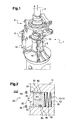
- the figure 1 presents an aircraft 1.
- This aircraft 1 comprises a hydraulic system 5 according to the invention.
- the aircraft 1 is provided with a mast 2 driving in rotation a rotor 3, such as the rotor of levitation and propulsion of a helicopter.
- This rotor 3 comprises a plurality of blades.
- the aircraft 1 is then provided with a set 4 of cyclic plates to control the pitch of the rotor blades 3.
- servocontrol type hydraulic systems 10 can then be used to operate the cyclic tray assembly.
- the invention can however be applied to other types of hydraulic system.
- the hydraulic system is provided with a hydraulic circuit including a cavity 12 formed in a body 11. This cavity 12 is filled with a fluid.
- the hydraulic system is provided with a closure device 20 for closing the cavity 12, and isolate it from a medium external to the hydraulic system called "outdoor EXT" convenience.
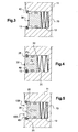
- the Figures 2 to 6 present a first embodiment
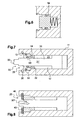
- the Figures 7 to 10 presenting a second embodiment of this closure device.
- the figure 11 shows a variant applicable to both embodiments.
- the closure device 10 comprises a plug 30 for closing the cavity 12.
- the plug 30 is thus shaped to the cavity 12, being of cylindrical shape according to the example shown.
- This plug 30 comprises a central portion 31 and a peripheral portion 32.
- the peripheral portion 32 is disposed around the central portion 31 to slide along an inner face 11 'of the body 11.
- the closure device 20 comprises a peripheral seal 50 for sealing between the plug 30 and the hydraulic system, more precisely between the plug 30 and the inner face 11 'delimiting the cavity 12 to be closed.
- the central portion 31 protrudes from the peripheral portion 32 outward EXT including.
- the plug 30 has a groove 25 delimited by a surface of the peripheral portion 32 facing the outside EXT called "contact surface 35".
- the groove 25 is open to the outside EXT and visible from the outside EXT.
- the central portion 31 and the peripheral portion 32 are integral with each other.
- the cap is for example a one-piece piece that can be functionally decomposed into a central portion and a peripheral portion.
- the peripheral portion 32 then includes, for example, at least one shoulder 33, 34 of the central portion 31.
- the plug comprises an upper shoulder 33 and a lower shoulder 34 extending from the peripheral wall of the central portion to the inner face 11 '.
- Each shoulder may be a ring disposed around the central portion.
- the upper shoulder 33 and the lower shoulder 34 at least partially represent the peripheral portion 32.
- the upper shoulder 33 is then provided with the contact surface 35.
- the upper shoulder 33 and the lower shoulder 34 are separated by an annular housing 85.
- the peripheral seal 50 is thus arranged in the annular housing 85.
- the central portion 31 slides in the peripheral portion 32.
- the central portion 31 may be a rod 31 'of the hydraulic system, such as a rod carrying a piston moving in the cavity 12.
- the peripheral portion represents a bearing placed around the central portion.
- This peripheral portion can, like the embodiment of the figure 2 have an upper shoulder, a lower shoulder and a housing accommodating a peripheral seal.
- an inner seal 60 may be interposed between the central portion and the peripheral portion. Nevertheless, it is possible not to implement such an internal seal, like the example of figures 8 and 9 .
- the closure device is further provided with an open snap ring 40.
- This elastic stop ring is intended to be inserted into the bore 13 while being arranged in the peripheral groove of the stopper 30.
- the elastic ring then serves to maintain the plug 30 in the cavity 12.
- the closure device 20 comprises a return means 70 for exerting pressure on the peripheral portion 32 in order to press against the elastic locking ring.
- the return means may comprise the pressurized fluid contained in the cavity 12, or even a spring 71 or the like interposed between the peripheral portion 32 and a seat 15 of the hydraulic system 5.
- the closure device 20 comprises a stop 14 formed in the hydraulic system 5.
- the peripheral portion 32 of the stopper can be arranged between the abutment 14 and the elastic locking ring 40.
- the stop 14 limits the axial displacement of the plug, in particular to avoid pushing the plug too far during assembly.
- the stop also serves to axially lock the peripheral portion 32. This stop ensures the proper positioning of the peripheral portion.
- the Figures 2 to 5 explain the method applied by an operator according to a variant of the first embodiment.
- the operator arranges, if necessary, the return means 70 and then the plug 30 in the cavity 12. Consequently, the operator exerts a force on the plug to drive it into the cavity along the arrow F1. The return means 70 is then compressed.
- the operator maintains his effort on the plug to compress the return means 70, and positions the elastic locking ring 40 in the bore 13 of the body 11.
- the operator then releases the cap 30.
- the return means relaxes and pushes the plug 30 outwards EXT along the arrow F2.
- the peripheral portion 32 abuts axially with its contact surface against the elastic stop ring 40 according to the arrow F2.
- the central portion 31 radially locking the elastic locking ring 40 along the arrow F3. The elastic locking ring 40 is thus locked in the groove 25.
- this resilient stop ring can come into contact with the central portion 31 in the zones 100, instead of being arranged in the groove 25. This position can easily be identified visually.
- the operator plates the cap against the abutment 14 and then positions the elastic stop ring.
- the operator arranges the peripheral portion 32 around the central portion 31.
- the central portion 31 can be refined at its free end 301.
- the operator then pushes the central portion into the cavity 12 to maximize the width of the groove 25 according to the arrow F4.
- the operator can then arrange the elastic ring 40 in the bore provided for this purpose.
- the operator then releases the central portion 31 to project an enlarged portion 302 of the central portion 31 relative to the peripheral portion.
- the operator can eventually pull the central portion for this purpose.
- the peripheral portion 32 abuts axially with its contact surface against the elastic locking ring 40 along the arrow F2.
- the enlarged portion 302 of the central portion 31 radially blocks the resilient stop ring 40 in the direction F5. The elastic locking ring 40 is thus locked in the groove 25.
- the variant of the figure 10 can be implemented by a method similar to the method described above.
- the peripheral portion 32 may comprise a contact surface 35 shaped to the elastic locking ring 40.
- the resilient stop ring is inscribed in the stopper penetrating into the contact surface.
- the elastic ring is thus placed in a recess of the plug.
- the holding in position of the elastic stop ring is then optimized.
- the elastic locking ring may be provided with two lugs 41 each comprising a perforation 42.
- the peripheral portion is then provided with a protruding protrusion into each perforation 42.
Landscapes
- Engineering & Computer Science (AREA)
- General Engineering & Computer Science (AREA)
- Mechanical Engineering (AREA)
- Physics & Mathematics (AREA)
- Fluid Mechanics (AREA)
- Pressure Vessels And Lids Thereof (AREA)
- Snaps, Bayonet Connections, Set Pins, And Snap Rings (AREA)
Abstract
Description
- La présente invention concerne un dispositif d'obturation d'un système hydraulique, un tel système hydraulique et un aéronef comportant ce système hydraulique. Plus particulièrement, l'invention concerne une servocommande d'aéronef.
- Les servocommandes sont notamment utilisées dans le domaine aéronautique pour le contrôle d'organes aérodynamiques. Par exemple, des servocommandes sont mises en oeuvre sur un hélicoptère pour contrôler le pas des pales du rotor de sustentation et de propulsion. En effet, un pilote peut alors transmettre un ordre aux servocommandes via des commandes de vol, les servocommandes agissant sur le pas des pales en fonction des ordres reçus.
- Les servocommandes peuvent être des servocommandes hydrauliques. Les commandes de vol agissent alors sur un distributeur hydraulique qui contrôle l'acheminement d'un fluide vers au moins un corps de la servocommande. Par suite, une servocommande hydraulique comporte un circuit hydraulique.
- Dès lors, une servocommande est usuellement munie d'un dispositif d'obturation de ce circuit hydraulique. Un tel dispositif d'obturation comprend un bouchon pour obturer un orifice du circuit hydraulique.
- Selon un premier état de la technique, le bouchon est conformé à l'orifice, en étant par exemple de forme cylindrique. Un joint annulaire est disposé dans une gorge du bouchon pour assurer l'étanchéité entre ce bouchon et la paroi délimitant l'orifice.
- De plus, le dispositif d'obturation comporte une collerette solidaire du bouchon. Le dispositif d'obturation peut être maintenu contre la servocommande par des vis fixant la collerette à ce corps. Un fil frein peut être utilisé pour freiner chaque vis.
- Selon un deuxième état de la technique, le dispositif d'obturation comporte une portion filetée prolongeant le bouchon. La portion filetée coopère alors avec un taraudage du corps.
- Un fil frein est alors utilisé pour relier la portion filetée au corps.
- Ces états de la technique sont relativement coûteux en temps d'usinage, et longs à installer.
- Selon un troisième état de la technique, le bouchon peut avoir une forme tronconique de dimensions légèrement supérieures aux dimensions de l'orifice à obturer. Le bouchon est alors inséré en force dans l'orifice selon la technique de montage connue sous l'expression « monté serré ».
- Un tel bouchon est parfois appelé « plug » en langue anglaise.
- Ce type de montage est employé pour obturer des orifices de petit diamètre. De plus, le démontage du bouchon s'avère délicat.
- Le document
GB 1584939 - Le document
EP 2 243 976 présente une bague coincée entre un logement et un bouchon. - La présente invention a alors pour objet de proposer un dispositif d'obturation alternatif visant à autoriser un montage simple et/ou peu coûteux.
- L'invention propose donc un dispositif d'obturation d'un système hydraulique, ce dispositif d'obturation comprenant un bouchon.
- De manière remarquable, le bouchon comporte une portion centrale coopérant avec une portion périphérique entourant cette portion centrale, le dispositif d'obturation incluant un anneau élastique d'arrêt ouvert apte à être inséré dans un alésage du système hydraulique. La portion centrale saille de la portion périphérique vers l'extérieur du système hydraulique pour ménager une gorge visible de l'extérieur, l'anneau élastique d'arrêt étant logé dans cette gorge et apte à être logé dans l'alésage, la portion périphérique butant axialement contre l'anneau élastique et la portion centrale bloquant radialement l'anneau élastique lorsque le dispositif d'obturation est correctement positionné.
- On rappelle qu'un anneau élastique d'arrêt est un anneau ouvert permettant de bloquer axialement un objet. Un tel anneau élastique d'arrêt est classiquement dénommé « circlip ». Un tel anneau peut être plat, contrairement à une bague de retenue vissée à un logement par exemple.
- Pour obturer une cavité d'un système hydraulique, un opérateur place alors le bouchon dans cette cavité, puis insère l'anneau élastique.
- A l'issue de l'installation, l'anneau élastique doit se trouver dans la gorge ménagée par le dispositif d'obturation, en étant agencé contre une surface de contact de la portion périphérique du bouchon.
- La mise en place du dispositif d'obturation est donc aisée, en ne nécessitant pas l'agencement d'un freinage particulier (fil frein...) ou un montage serré par exemple. Le maintien du dispositif d'obturation est garanti par le blocage axial de l'anneau élastique dans l'alésage.
- De plus, un opérateur peut s'assurer visuellement de la bonne installation du dispositif d'obturation. En effet, si l'anneau élastique n'est pas correctement plaqué contre la portion périphérique, cet opérateur en déduit que le dispositif d'obturation n'est pas correctement agencé.
- Il est à noter que les anneaux élastiques d'arrêt sont utilisés dans l'industrie de manière générale, mais sont peu voire pas utilisés dans le domaine aéronautique. L'utilisation d'un tel anneau dans le cadre par exemple d'une servocommande d'aéronef n'a alors rien d'évident.
- En effet et selon les préjugés en vigueur, il est difficile de s'assurer qu'un anneau élastique d'arrêt est correctement positionné. Cette première difficulté est résolue par l'invention qui propose un agencement autorisant un simple contrôle visuel.
- De plus, selon ces préjugés, le maintien d'un anneau élastique d'arrêt dans la position requise est délicat à garantir dans le cadre d'un aéronef soumis à de fortes vibrations. Cette deuxième difficulté est résolue par l'introduction d'un effort axial exercé par la paroi périphérique sur l'anneau élastique d'arrêt, et par l'introduction d'un blocage radial dans le plan de l'anneau par la paroi centrale notamment.
- L'invention tend donc à lever les préjugés ayant terni l'image des anneaux élastiques d'arrêt dans le domaine aéronautique, jusqu'à quasiment empêcher leur utilisation dans ce domaine technique particulier.
- L'invention propose donc un dispositif d'obturation simple en rupture des idées préconçues courantes, ce dispositif d'obturation étant associé à un procédé de montage simple et peu onéreux.
- Ce dispositif d'obturation peut comporter une ou plusieurs des caractéristiques additionnelles qui suivent.
- Selon une version, un fluide peut éventuellement partiellement fuir en passant entre le bouchon et le système hydraulique. Le dispositif d'obturation n'est alors pas totalement étanche. Une telle fuite peut éventuellement être maitrisée et drainée par exemple.
- Cependant, selon une version alternative, le dispositif d'obturation peut comporter un joint périphérique pour assurer une étanchéité entre le bouchon et le système hydraulique. Un joint périphérique est par exemple agencé entre la portion périphérique et la paroi interne délimitant la cavité à obturer.
- Selon un premier mode de réalisation, la portion centrale et la portion périphérique sont solidaires l'une de l'autre, la portion périphérique représentant au moins un épaulement de la portion centrale.
- Le bouchon est par exemple réalisé d'un seul tenant de manière à présenter d'une part la portion centrale et, d'autre part, la portion périphérique.
- Cette portion périphérique peut comporter un épaulement supérieur et un épaulement inférieur de la portion centrale qui sont séparés par un logement annulaire. Un joint périphérique peut alors être agencé dans ce logement annulaire pour assurer une étanchéité entre le bouchon et le système hydraulique. L'épaulement supérieur est alors en contact avec l'anneau élastique d'arrêt lorsque le dispositif d'obturation est correctement positionné.
- Selon un deuxième mode de réalisation, la portion centrale coulisse dans la portion périphérique.
- Par exemple, la portion centrale comporte une tige du système hydraulique, telle qu'une tige portant un piston. La portion centrale du bouchon est donc un élément fonctionnel mobile du système hydraulique.
- Eventuellement, le dispositif d'obturation comporte un joint interne interposé entre la portion centrale et la portion périphérique. Néanmoins, il est possible de ne pas implémenter un tel joint interne, en tolérant une éventuellement fuite maitrisée et drainée.
- Par ailleurs pour garantir que la portion périphérique est correctement positionnée et selon une première variante, le dispositif d'obturation comporte une butée ménagée dans le système hydraulique, la portion périphérique étant en contact contre la butée et l'anneau élastique d'arrêt dans des conditions normales.
- Ainsi, un opérateur appuie sur la portion périphérique pour l'accoler à la butée.
- Selon une deuxième variante, le dispositif d'obturation comporte un moyen de rappel pour tendre à pousser la portion périphérique en dehors du système hydraulique.
- Lors de la mise en place du dispositif d'obturation, l'opérateur exerce une pression sur la portion périphérique pour comprimer le moyen de rappel. Dès lors, l'opérateur peut insérer l'anneau élastique d'arrêt dans l'alésage du système hydraulique prévu à cet effet. L'opérateur relâche ensuite la portion périphérique. Le moyen de rappel exerce par suite un effort sur cette portion périphérique pour la plaquer contre l'anneau élastique d'arrêt.
- Si la portion périphérique n'est pas correctement plaquée contre cet anneau élastique d'arrêt, l'opérateur en conclut que le dispositif d'obturation est mal positionné et recommence son installation.
- Le moyen de rappel peut être un fluide présent dans la cavité à obturer, la pression du fluide dans cette cavité permettant d'exercer la force de rappel requise. Le fluide peut être un liquide ou un gaz.
- De manière alternative, le moyen de rappel est un ressort interposé entre la portion périphérique et un siège du système hydraulique.
- Par ailleurs, la portion périphérique peut comprendre une surface de contact conformée à l'anneau élastique d'arrêt afin que l'anneau élastique d'arrêt soit inscrit dans la portion périphérique lorsque le dispositif d'obturation est correctement positionné dans la gorge.
- Cette caractéristique facilite l'inspection visuelle du dispositif d'obturation.
- L'invention vise aussi un système hydraulique muni d'un circuit hydraulique comportant une cavité ouverte sur l'extérieur du système hydraulique. Ce système hydraulique comporte alors un dispositif d'obturation du type décrit précédemment pour obturer ladite cavité.
- Le système hydraulique peut être de manière intéressante une servocommande d'aéronef.
- De même, l'invention vise un aéronef ayant un dispositif d'obturation du type décrit précédemment.
- L'invention et ses avantages apparaîtront avec plus de détails dans le cadre de la description qui suit avec des exemples de réalisation donnés à titre illustratif en référence aux figures annexées qui représentent :
- la
figure 1 , un schéma présentant un aéronef muni d'une servocommande selon l'invention, - les
figures 2 à 6 , des schémas explicitant un premier mode de réalisation, - les
figures 7 à 10 , des schémas explicitant un deuxième mode de réalisation, et - la
figure 11 , un schéma présentant une portion périphérique conformée à la forme d'un anneau élastique. - Les éléments présents dans plusieurs figures distinctes sont affectés d'une seule et même référence.
- La
figure 1 présente un aéronef 1. Cet aéronef 1 comporte un système hydraulique 5 selon l'invention. - Plus particulièrement, l'aéronef 1 est pourvu d'un mât 2 entraînant en rotation un rotor 3, tel que le rotor de sustentation et de propulsion d'un hélicoptère. Ce rotor 3 comporte une pluralité de pales. L'aéronef 1 est alors muni d'un ensemble 4 de plateaux cycliques pour contrôler le pas des pales du rotor 3.
- Plusieurs systèmes hydrauliques 5 de type servocommande 10 peuvent alors être utilisés pour manoeuvrer l'ensemble 5 de plateaux cycliques. L'invention peut toutefois s'appliquer à d'autres types de système hydraulique.
- En référence à la
figure 2 , le système hydraulique est muni d'un circuit hydraulique possédant notamment une cavité 12 ménagée dans un corps 11. Cette cavité 12 est remplie par un fluide. - Dès lors, le système hydraulique est pourvu d'un dispositif d'obturation 20 pour obturer la cavité 12, et l'isoler d'un milieu extérieur au système hydraulique dénommé par commodité « extérieur EXT ».
- Les
figures 2 à 6 présentent un premier mode de réalisation, lesfigures 7 à 10 présentant un deuxième mode de réalisation de ce dispositif d'obturation. Lafigure 11 montre une variante applicable aux deux modes de réalisation. - En référence à la
figure 2 et indépendamment du mode de réalisation, le dispositif d'obturation 10 comporte un bouchon 30 pour obturer la cavité 12. - Le bouchon 30 est donc conformé à la cavité 12, en étant de forme cylindrique selon l'exemple représenté.
- Ce bouchon 30 comprend une portion centrale 31 et une portion périphérique 32. La portion périphérique 32 est disposée autour de la portion centrale 31 pour coulisser le long d'une face interne 11' du corps 11.
- Eventuellement, le dispositif d'obturation 20 comporte un joint périphérique 50 pour assurer l'étanchéité entre le bouchon 30 et le système hydraulique, plus précisément entre le bouchon 30 et la face interne 11' délimitant la cavité 12 à obturer.
- Par ailleurs, la portion centrale 31 saille de la portion périphérique 32 vers l'extérieur EXT notamment.
- Ainsi, le bouchon 30 présente une gorge 25 délimitée par une surface de la portion périphérique 32 en regard de l'extérieur EXT dénommée « surface de contact 35 ». La gorge 25 est donc ouverte sur l'extérieur EXT et visible de l'extérieur EXT.
- Selon le premier mode de réalisation de la
figure 2 , la portion centrale 31 et la portion périphérique 32 sont solidaires l'une de l'autre. Le bouchon est par exemple une pièce monobloc pouvant être décomposée fonctionnellement en une portion centrale et une portion périphérique. - La portion périphérique 32 inclut alors par exemple au moins un épaulement 33, 34 de la portion centrale 31.
- Ainsi, le bouchon comprend un épaulement supérieur 33 et un épaulement inférieur 34 s'étendant à partir de la paroi périphérique de la portion centrale vers la face interne 11'. Chaque épaulement peut être un anneau disposé autour de la portion centrale.
- Dès lors, l'épaulement supérieur 33 et l'épaulement inférieur 34 représentent au moins en partie la portion périphérique 32. L'épaulement supérieur 33 est alors muni de la surface de contact 35.
- De plus, l'épaulement supérieur 33 et l'épaulement inférieur 34 sont séparés par un logement annulaire 85. Le joint périphérique 50 est ainsi agencé dans le logement annulaire 85.
- Selon le deuxième mode de réalisation de la
figure 7 , la portion centrale 31 coulisse dans la portion périphérique 32. - En effet, la portion centrale 31 peut être une tige 31' du système hydraulique, telle qu'une tige portant un piston évoluant dans la cavité 12.
- La portion périphérique représente un palier placé autour de la portion centrale.
- Cette portion périphérique peut à l'instar du mode de réalisation de la
figure 2 présenter un épaulement supérieur, un épaulement inférieur et un logement accueillant un joint périphérique. - De plus, un joint interne 60 peut être interposé entre la portion centrale et la portion périphérique. Néanmoins, il est possible de ne pas implémenter un tel joint interne, à l'instar de l'exemple des
figures 8 et9 . - En référence à le
figure 2 et indépendamment du mode de réalisation, le dispositif d'obturation est en outre muni d'un anneau élastique d'arrêt 40 ouvert. Cet anneau élastique d'arrêt est destiné à être inséré dans l'alésage 13 tout en étant disposé dans la gorge 25 périphérique du bouchon 30. - L'anneau élastique a alors pour fonction de maintenir le bouchon 30 dans la cavité 12.
- Par ailleurs selon une variante schématisée sur les
figures 2 et10 notamment, le dispositif d'obturation 20 comporte un moyen de rappel 70 pour exercer une pression sur la portion périphérique 32 afin de la plaquer contre l'anneau élastique d'arrêt. - Le moyen de rappel peut comprendre le fluide sous pression contenu dans la cavité 12, voire un ressort 71 ou équivalent interposé entre la portion périphérique 32 et un siège 15 du système hydraulique 5.
- Selon une variante schématisée sur les
figures 6 et 7 notamment, le dispositif d'obturation 20 comporte une butée 14 ménagée dans le système hydraulique 5. La portion périphérique 32 du bouchon peut être agencée entre la butée 14 et l'anneau élastique d'arrêt 40. - Selon la variante de la figura 6, la butée 14 permet de limiter le déplacement axial du bouchon, notamment afin d'éviter de pousser le bouchon trop loin lors du montage.
- Selon la variante de la
figure 7 , la butée permet aussi de bloquer axialement la portion périphérique 32. Cette butée assure le bon positionnement de la portion périphérique. - Les
figures 2 à 5 explicitent le procédé appliqué par un opérateur selon une variante du premier mode de réalisation. - En référence à la
figure 2 , l'opérateur agence le cas échéant le moyen de rappel 70 puis le bouchon 30 dans la cavité 12. Dès lors, l'opérateur exerce un effort sur le bouchon pour l'enfoncer dans la cavité selon la flèche F1. Le moyen de rappel 70 est alors comprimé. - En référence à la
figure 3 , l'opérateur maintient son effort sur le bouchon pour comprimer le moyen de rappel 70, et positionne l'anneau élastique d'arrêt 40 dans l'alésage 13 du corps 11. - En référence à la
figure 4 , l'opérateur relâche ensuite le bouchon 30. Le moyen de rappel se détend et pousse le bouchon 30 vers l'extérieur EXT selon la flèche F2. - Si le dispositif d'obturation est correctement positionné, la portion périphérique 32 bute axialement avec sa surface de contact contre l'anneau élastique d'arrêt 40 selon la flèche F2. De plus, la portion centrale 31 bloquant radialement l'anneau élastique d'arrêt 40 selon la flèche F3. L'anneau élastique d'arrêt 40 est ainsi bloqué dans la gorge 25.
- Ce bon positionnement peut facilement être visualisé par l'opérateur.
- En effet, et en référence à la
figure 5 , si l'anneau élastique d'arrêt 40 est mal positionné, cet anneau élastique d'arrêt peut entrer en contact avec la portion centrale 31 dans les zones 100, au lieu d'être agencé dans la gorge 25. Cette position peut facilement être identifiée visuellement. - Pour mettre en oeuvre la variante de la
figure 6 , l'opérateur plaque le bouchon contre la butée 14 puis positionne l'anneau élastique d'arrêt. - Les
figures 7 à 9 explicitent le procédé appliqué par un opérateur selon une variante du deuxième mode de réalisation. - En référence à la
figure 7 , l'opérateur agence la portion périphérique 32 autour de la portion centrale 31. - Dès lors, l'opérateur exerce un effort sur la portion périphérique pour plaquer la portion périphérique contre une butée 14.
- En référence à la
figure 8 , la portion centrale 31 peut être affinée à son extrémité libre 301. L'opérateur pousse alors la portion centrale dans la cavité 12 pour maximiser la largeur de la gorge 25 selon la flèche F4. L'opérateur peut alors agencer l'anneau élastique 40 dans l'alésage prévu à cet effet. - En référence à la
figure 9 , l'opérateur relâche ensuite la portion centrale 31 pour faire saillir une portion élargie 302 de la portion centrale 31 par rapport à la portion périphérique. - L'opérateur peut éventuellement tirer la portion centrale à cet effet.
- Si le dispositif d'obturation est correctement positionné, la portion périphérique 32 bute axialement avec sa surface de contact contre l'anneau élastique d'arrêt 40 selon la flèche F2. De plus, la portion élargie 302 de la portion centrale 31 bloque radialement l'anneau élastique d'arrêt 40 selon la direction F5. L'anneau élastique d'arrêt 40 est ainsi bloqué dans la gorge 25.
- Ce bon positionnement peut facilement être visualisé par l'opérateur.
- La variante de la
figure 10 peut être mise en place selon un procédé similaire au procédé décrit précédemment. - Par ailleurs et en référence à la
figure 11 , la portion périphérique 32 peut comprendre une surface de contact 35 conformée à l'anneau élastique d'arrêt 40. - Dès lors et lorsque le dispositif d'obturation 20 est correctement positionné, l'anneau élastique d'arrêt est inscrit dans le bouchon en pénétrant dans la surface de contact. L'anneau élastique est ainsi placé dans un évidement du bouchon.
- Le maintien en position de l'anneau élastique d'arrêt est alors optimisé.
- De plus, l'anneau élastique d'arrêt peut être muni de deux oreilles 41 comprenant chacune une perforation 42. La portion périphérique est alors munie d'une excroissance pénétrant dans chaque perforation 42.
- Naturellement, la présente invention est sujette à de nombreuses variations quant à sa mise en oeuvre. Bien que plusieurs modes de réalisation aient été décrits, on comprend bien qu'il n'est pas concevable d'identifier de manière exhaustive tous les modes possibles. Il est bien sûr envisageable de remplacer un moyen décrit par un moyen équivalent sans sortir du cadre de la présente invention.
Claims (15)
- Dispositif d'obturation (20) d'un système hydraulique (5), ledit dispositif d'obturation (20) comprenant un bouchon (30),
caractérisé en ce que, ledit bouchon (30) comporte une portion centrale (31) coopérant avec une portion périphérique (32) entourant ladite portion centrale (31), le dispositif d'obturation (20) incluant un anneau élastique d'arrêt (40) ouvert apte à être inséré dans un alésage (13) du système hydraulique (5), ladite portion centrale (31) saillant de ladite portion périphérique (32) vers l'extérieur (EXT) du système hydraulique (5) pour ménager une gorge (25) visible de l'extérieur (EXT), ledit anneau élastique d'arrêt (40) étant logé dans cette gorge (25) et apte à être logé dans l'alésage, ladite portion périphérique (32) butant axialement contre l'anneau élastique d'arrêt (40) et ladite portion centrale (31) bloquant radialement ledit anneau élastique d'arrêt (40) lorsque le dispositif d'obturation est correctement positionné. - Dispositif selon la revendication 1,
caractérisé en ce que ledit dispositif d'obturation (20) comporte un joint périphérique (50) pour assurer une étanchéité entre ledit bouchon (30) et ledit système hydraulique (5). - Dispositif selon l'une quelconque des revendications 1 à 2,
caractérisé en ce que ladite portion centrale (31) et ladite portion périphérique (32) sont solidaires l'une de l'autre, ladite portion périphérique (32) représentant au moins un épaulement (33, 34) de ladite portion centrale (31). - Dispositif selon l'une quelconque des revendications 1 à 3,
caractérisé en ce que ladite portion périphérique (32) comporte un épaulement supérieur (33) et un épaulement inférieur (34) de la portion centrale (31) qui sont séparés par un logement annulaire (85, un joint périphérique (50) étant agencé dans ledit logement annulaire (85) pour assurer une étanchéité entre ledit bouchon (30) et ledit système hydraulique (5), ledit épaulement supérieur (33) devant être en contact avec ledit anneau élastique d'arrêt (40). - Dispositif selon l'une quelconque des revendications 1 à 2,
caractérisé en ce que ladite portion centrale (31) coulisse dans ladite portion périphérique (32). - Dispositif selon la revendication 5,
caractérisé en ce que ladite portion centrale (31) comporte une tige (31') dudit système hydraulique (5). - Dispositif selon l'une quelconque des revendications 5 à 6,
caractérisé en ce que ledit dispositif d'obturation (20) comporte un joint interne (60) interposé entre ladite portion centrale (31) et ladite portion périphérique (32). - Dispositif selon l'une quelconque des revendications 1 à 7,
caractérisé en ce que ledit dispositif d'obturation (20) comporte une butée (14) ménagée dans le système hydraulique (5), ladite portion périphérique (32) étant en contact contre ladite butée (14) et ledit anneau élastique d'arrêt (40). - Dispositif selon l'une quelconque des revendications 1 à 8,
caractérisé en ce que ledit dispositif d'obturation (20) comporte un moyen de rappel (70) pour tendre à pousser ladite portion périphérique (32) en dehors du système hydraulique (5). - Dispositif selon la revendication 9,
caractérisé en ce que ledit moyen de rappel (70) est un ressort (71) interposé entre la portion périphérique (32) et un siège (15) du système hydraulique (5). - Dispositif selon l'une quelconque des revendications 1 à 10,
caractérisé en ce que ladite portion périphérique (32) comprend une surface de contact (35) conformée à l'anneau élastique d'arrêt (40) afin que ledit anneau élastique d'arrêt (40) soit inscrit dans la portion périphérique (32) lorsque le dispositif d'obturation (20) est correctement positionné dans la gorge (25). - Dispositif selon l'une quelconque des revendications 1 à 11,
caractérisé en ce que ledit anneau est plat. - Système hydraulique (5) muni d'un circuit hydraulique comportant une cavité (12) ouverte sur l'extérieur (EXT) du système hydraulique (5),
caractérisé en ce que le système hydraulique (5) comporte un dispositif d'obturation (20) selon l'une quelconque des revendications 1 à 12 pour obturer ladite cavité (12). - Système hydraulique selon la revendication 13,
caractérisé en ce que le système hydraulique (5) est une servocommande (10) d'aéronef. - Aéronef (1),
caractérisé en ce que cet aéronef (1) comporte un système hydraulique (5) selon l'une quelconque des revendications 13 à 14.
Applications Claiming Priority (1)
| Application Number | Priority Date | Filing Date | Title |
|---|---|---|---|
| FR1300557A FR3003327B1 (fr) | 2013-03-13 | 2013-03-13 | Dispositif d obturation d un systeme hydraulique systeme hydraulique et aeronef |
Publications (2)
| Publication Number | Publication Date |
|---|---|
| EP2778438A1 true EP2778438A1 (fr) | 2014-09-17 |
| EP2778438B1 EP2778438B1 (fr) | 2016-11-30 |
Family
ID=48692552
Family Applications (1)
| Application Number | Title | Priority Date | Filing Date |
|---|---|---|---|
| EP14000414.4A Active EP2778438B1 (fr) | 2013-03-13 | 2014-02-05 | Dispositif d'obturation d'un système hydraulique, système hydraulique et aéronef |
Country Status (2)
| Country | Link |
|---|---|
| EP (1) | EP2778438B1 (fr) |
| FR (1) | FR3003327B1 (fr) |
Cited By (1)
| Publication number | Priority date | Publication date | Assignee | Title |
|---|---|---|---|---|
| DE102017218140A1 (de) * | 2017-10-11 | 2019-04-11 | Hawe Hydraulik Se | Drucksystemkomponente, Werkzeug zur Demontage einer Drucksystemkomponente, Drucksystem mit einer Drucksystemkomponente und Verfahren zur Demontage einer Drucksystemkomponente |
Citations (3)
| Publication number | Priority date | Publication date | Assignee | Title |
|---|---|---|---|---|
| US2989972A (en) * | 1959-05-18 | 1961-06-27 | Chrysler Corp | Accumulator charging mechanism |
| GB1584939A (en) | 1977-05-26 | 1981-02-18 | United Technologies Corp | Jam proof piston |
| EP2243976A1 (fr) | 2009-04-21 | 2010-10-27 | Special Springs S.r.l. | Actionneur de cylindre de gaz doté d'un dispositif de sécurité pour l'éjection contrôlée d'une tige de piston |
-
2013
- 2013-03-13 FR FR1300557A patent/FR3003327B1/fr active Active
-
2014
- 2014-02-05 EP EP14000414.4A patent/EP2778438B1/fr active Active
Patent Citations (3)
| Publication number | Priority date | Publication date | Assignee | Title |
|---|---|---|---|---|
| US2989972A (en) * | 1959-05-18 | 1961-06-27 | Chrysler Corp | Accumulator charging mechanism |
| GB1584939A (en) | 1977-05-26 | 1981-02-18 | United Technologies Corp | Jam proof piston |
| EP2243976A1 (fr) | 2009-04-21 | 2010-10-27 | Special Springs S.r.l. | Actionneur de cylindre de gaz doté d'un dispositif de sécurité pour l'éjection contrôlée d'une tige de piston |
Cited By (2)
| Publication number | Priority date | Publication date | Assignee | Title |
|---|---|---|---|---|
| DE102017218140A1 (de) * | 2017-10-11 | 2019-04-11 | Hawe Hydraulik Se | Drucksystemkomponente, Werkzeug zur Demontage einer Drucksystemkomponente, Drucksystem mit einer Drucksystemkomponente und Verfahren zur Demontage einer Drucksystemkomponente |
| DE102017218140B4 (de) | 2017-10-11 | 2023-05-04 | Hawe Hydraulik Se | Drucksystemkomponente, Werkzeug zur Demontage einer Drucksystemkomponente, Drucksystem mit einer Drucksystemkomponente und Verfahren zur Demontage einer Drucksystemkomponente |
Also Published As
| Publication number | Publication date |
|---|---|
| FR3003327B1 (fr) | 2015-07-31 |
| FR3003327A1 (fr) | 2014-09-19 |
| EP2778438B1 (fr) | 2016-11-30 |
Similar Documents
| Publication | Publication Date | Title |
|---|---|---|
| EP2771598B1 (fr) | Robinet d'isolement | |
| EP3253951B1 (fr) | Bouchon anti-corrosion pour combler un orifice de fixation et système comprenant ledit bouchon | |
| EP3625489B1 (fr) | Valve de gonflage pour pneu amelioree | |
| FR2819864A1 (fr) | Dispositif de butee de debrayage autocentreuse | |
| EP3204654B1 (fr) | Assemblage de deux pièces comprenant une coupelle de centrage amovible pour turbomachine d'aéronef | |
| JP6745123B2 (ja) | 極低温用玉形弁 | |
| EP3483670B1 (fr) | Soupape de sécurité pour montre | |
| EP2817548A1 (fr) | Dispositif de raccordement étanche sans zone de rétention | |
| CN103574030B (zh) | 密封构造体 | |
| EP1845235A1 (fr) | Dispositif de rétention axiale d'un flasque de disque de rotor de turbomachine | |
| EP2354002B1 (fr) | Procédé et dispositif pour vidanger un réservoir, réservoir et aéronef muni d'un tel dispositif | |
| EP2778438B1 (fr) | Dispositif d'obturation d'un système hydraulique, système hydraulique et aéronef | |
| EP1780427B1 (fr) | Rondelle d'ancrage non agressive | |
| EP3432085B1 (fr) | Soupape de sécurité pour pièce d'horlogerie | |
| EP2567101B1 (fr) | Verin a course declenchee presentant des moyens d'etancheite et des moyens de blocage de la tige. | |
| EP2364911A1 (fr) | Dispositif de remplissage d'un réservoir par gravité ou sous pression | |
| CA2918800C (fr) | Capteur de proximite pour aeronef dote d'un fusible hydraulique | |
| EP1489713A1 (fr) | Dispositif de traversée étanche de paroi | |
| EP3488964B1 (fr) | Procédé de dégagement d'un axe creux d'une liaison pivot entre un premier élément et un deuxième élément | |
| EP3749539B1 (fr) | Ensemble d'alimentation en carburant ou en produit de depollution d'un vehicule automobile | |
| FR3092892A1 (fr) | Dispositif de raccordement d’un tube a rupture sonore | |
| WO2006042936A1 (fr) | Cartouche de raccordement demontable | |
| FR2916023A1 (fr) | Liaison mecanique fusible entre deux ecrous sur un ensemble a vis de securite a defaillance. | |
| EP3264536B1 (fr) | Dispositif de fixation à verrouillage pour connecteurs électriques en deux parties à accouplage axial | |
| FR2881502A1 (fr) | Dispositif de raccordement auto-extractible |
Legal Events
| Date | Code | Title | Description |
|---|---|---|---|
| PUAI | Public reference made under article 153(3) epc to a published international application that has entered the european phase |
Free format text: ORIGINAL CODE: 0009012 |
|
| 17P | Request for examination filed |
Effective date: 20140205 |
|
| AK | Designated contracting states |
Kind code of ref document: A1 Designated state(s): AL AT BE BG CH CY CZ DE DK EE ES FI FR GB GR HR HU IE IS IT LI LT LU LV MC MK MT NL NO PL PT RO RS SE SI SK SM TR |
|
| AX | Request for extension of the european patent |
Extension state: BA ME |
|
| R17P | Request for examination filed (corrected) |
Effective date: 20141208 |
|
| RBV | Designated contracting states (corrected) |
Designated state(s): AL AT BE BG CH CY CZ DE DK EE ES FI FR GB GR HR HU IE IS IT LI LT LU LV MC MK MT NL NO PL PT RO RS SE SI SK SM TR |
|
| GRAP | Despatch of communication of intention to grant a patent |
Free format text: ORIGINAL CODE: EPIDOSNIGR1 |
|
| INTG | Intention to grant announced |
Effective date: 20160818 |
|
| GRAS | Grant fee paid |
Free format text: ORIGINAL CODE: EPIDOSNIGR3 |
|
| GRAA | (expected) grant |
Free format text: ORIGINAL CODE: 0009210 |
|
| AK | Designated contracting states |
Kind code of ref document: B1 Designated state(s): AL AT BE BG CH CY CZ DE DK EE ES FI FR GB GR HR HU IE IS IT LI LT LU LV MC MK MT NL NO PL PT RO RS SE SI SK SM TR |
|
| REG | Reference to a national code |
Ref country code: CH Ref legal event code: EP Ref country code: GB Ref legal event code: FG4D Free format text: NOT ENGLISH |
|
| REG | Reference to a national code |
Ref country code: AT Ref legal event code: REF Ref document number: 850084 Country of ref document: AT Kind code of ref document: T Effective date: 20161215 |
|
| REG | Reference to a national code |
Ref country code: IE Ref legal event code: FG4D Free format text: LANGUAGE OF EP DOCUMENT: FRENCH |
|
| REG | Reference to a national code |
Ref country code: DE Ref legal event code: R096 Ref document number: 602014005088 Country of ref document: DE |
|
| REG | Reference to a national code |
Ref country code: FR Ref legal event code: PLFP Year of fee payment: 4 |
|
| PG25 | Lapsed in a contracting state [announced via postgrant information from national office to epo] |
Ref country code: LV Free format text: LAPSE BECAUSE OF FAILURE TO SUBMIT A TRANSLATION OF THE DESCRIPTION OR TO PAY THE FEE WITHIN THE PRESCRIBED TIME-LIMIT Effective date: 20161130 |
|
| REG | Reference to a national code |
Ref country code: LT Ref legal event code: MG4D |
|
| REG | Reference to a national code |
Ref country code: NL Ref legal event code: MP Effective date: 20161130 |
|
| REG | Reference to a national code |
Ref country code: AT Ref legal event code: MK05 Ref document number: 850084 Country of ref document: AT Kind code of ref document: T Effective date: 20161130 |
|
| PG25 | Lapsed in a contracting state [announced via postgrant information from national office to epo] |
Ref country code: LT Free format text: LAPSE BECAUSE OF FAILURE TO SUBMIT A TRANSLATION OF THE DESCRIPTION OR TO PAY THE FEE WITHIN THE PRESCRIBED TIME-LIMIT Effective date: 20161130 Ref country code: NO Free format text: LAPSE BECAUSE OF FAILURE TO SUBMIT A TRANSLATION OF THE DESCRIPTION OR TO PAY THE FEE WITHIN THE PRESCRIBED TIME-LIMIT Effective date: 20170228 Ref country code: SE Free format text: LAPSE BECAUSE OF FAILURE TO SUBMIT A TRANSLATION OF THE DESCRIPTION OR TO PAY THE FEE WITHIN THE PRESCRIBED TIME-LIMIT Effective date: 20161130 Ref country code: GR Free format text: LAPSE BECAUSE OF FAILURE TO SUBMIT A TRANSLATION OF THE DESCRIPTION OR TO PAY THE FEE WITHIN THE PRESCRIBED TIME-LIMIT Effective date: 20170301 |
|
| PG25 | Lapsed in a contracting state [announced via postgrant information from national office to epo] |
Ref country code: PT Free format text: LAPSE BECAUSE OF FAILURE TO SUBMIT A TRANSLATION OF THE DESCRIPTION OR TO PAY THE FEE WITHIN THE PRESCRIBED TIME-LIMIT Effective date: 20170330 Ref country code: PL Free format text: LAPSE BECAUSE OF FAILURE TO SUBMIT A TRANSLATION OF THE DESCRIPTION OR TO PAY THE FEE WITHIN THE PRESCRIBED TIME-LIMIT Effective date: 20161130 Ref country code: ES Free format text: LAPSE BECAUSE OF FAILURE TO SUBMIT A TRANSLATION OF THE DESCRIPTION OR TO PAY THE FEE WITHIN THE PRESCRIBED TIME-LIMIT Effective date: 20161130 Ref country code: HR Free format text: LAPSE BECAUSE OF FAILURE TO SUBMIT A TRANSLATION OF THE DESCRIPTION OR TO PAY THE FEE WITHIN THE PRESCRIBED TIME-LIMIT Effective date: 20161130 Ref country code: FI Free format text: LAPSE BECAUSE OF FAILURE TO SUBMIT A TRANSLATION OF THE DESCRIPTION OR TO PAY THE FEE WITHIN THE PRESCRIBED TIME-LIMIT Effective date: 20161130 Ref country code: BE Free format text: LAPSE BECAUSE OF NON-PAYMENT OF DUE FEES Effective date: 20170228 Ref country code: AT Free format text: LAPSE BECAUSE OF FAILURE TO SUBMIT A TRANSLATION OF THE DESCRIPTION OR TO PAY THE FEE WITHIN THE PRESCRIBED TIME-LIMIT Effective date: 20161130 Ref country code: RS Free format text: LAPSE BECAUSE OF FAILURE TO SUBMIT A TRANSLATION OF THE DESCRIPTION OR TO PAY THE FEE WITHIN THE PRESCRIBED TIME-LIMIT Effective date: 20161130 |
|
| PG25 | Lapsed in a contracting state [announced via postgrant information from national office to epo] |
Ref country code: NL Free format text: LAPSE BECAUSE OF FAILURE TO SUBMIT A TRANSLATION OF THE DESCRIPTION OR TO PAY THE FEE WITHIN THE PRESCRIBED TIME-LIMIT Effective date: 20161130 |
|
| PG25 | Lapsed in a contracting state [announced via postgrant information from national office to epo] |
Ref country code: DK Free format text: LAPSE BECAUSE OF FAILURE TO SUBMIT A TRANSLATION OF THE DESCRIPTION OR TO PAY THE FEE WITHIN THE PRESCRIBED TIME-LIMIT Effective date: 20161130 Ref country code: RO Free format text: LAPSE BECAUSE OF FAILURE TO SUBMIT A TRANSLATION OF THE DESCRIPTION OR TO PAY THE FEE WITHIN THE PRESCRIBED TIME-LIMIT Effective date: 20161130 Ref country code: CZ Free format text: LAPSE BECAUSE OF FAILURE TO SUBMIT A TRANSLATION OF THE DESCRIPTION OR TO PAY THE FEE WITHIN THE PRESCRIBED TIME-LIMIT Effective date: 20161130 Ref country code: EE Free format text: LAPSE BECAUSE OF FAILURE TO SUBMIT A TRANSLATION OF THE DESCRIPTION OR TO PAY THE FEE WITHIN THE PRESCRIBED TIME-LIMIT Effective date: 20161130 Ref country code: SK Free format text: LAPSE BECAUSE OF FAILURE TO SUBMIT A TRANSLATION OF THE DESCRIPTION OR TO PAY THE FEE WITHIN THE PRESCRIBED TIME-LIMIT Effective date: 20161130 |
|
| PG25 | Lapsed in a contracting state [announced via postgrant information from national office to epo] |
Ref country code: SM Free format text: LAPSE BECAUSE OF FAILURE TO SUBMIT A TRANSLATION OF THE DESCRIPTION OR TO PAY THE FEE WITHIN THE PRESCRIBED TIME-LIMIT Effective date: 20161130 Ref country code: BG Free format text: LAPSE BECAUSE OF FAILURE TO SUBMIT A TRANSLATION OF THE DESCRIPTION OR TO PAY THE FEE WITHIN THE PRESCRIBED TIME-LIMIT Effective date: 20170228 |
|
| REG | Reference to a national code |
Ref country code: DE Ref legal event code: R097 Ref document number: 602014005088 Country of ref document: DE |
|
| REG | Reference to a national code |
Ref country code: DE Ref legal event code: R119 Ref document number: 602014005088 Country of ref document: DE |
|
| PG25 | Lapsed in a contracting state [announced via postgrant information from national office to epo] |
Ref country code: MC Free format text: LAPSE BECAUSE OF FAILURE TO SUBMIT A TRANSLATION OF THE DESCRIPTION OR TO PAY THE FEE WITHIN THE PRESCRIBED TIME-LIMIT Effective date: 20161130 |
|
| REG | Reference to a national code |
Ref country code: CH Ref legal event code: PL |
|
| PLBE | No opposition filed within time limit |
Free format text: ORIGINAL CODE: 0009261 |
|
| STAA | Information on the status of an ep patent application or granted ep patent |
Free format text: STATUS: NO OPPOSITION FILED WITHIN TIME LIMIT |
|
| PG25 | Lapsed in a contracting state [announced via postgrant information from national office to epo] |
Ref country code: CH Free format text: LAPSE BECAUSE OF NON-PAYMENT OF DUE FEES Effective date: 20170228 Ref country code: LI Free format text: LAPSE BECAUSE OF NON-PAYMENT OF DUE FEES Effective date: 20170228 |
|
| 26N | No opposition filed |
Effective date: 20170831 |
|
| REG | Reference to a national code |
Ref country code: IE Ref legal event code: MM4A |
|
| PG25 | Lapsed in a contracting state [announced via postgrant information from national office to epo] |
Ref country code: SI Free format text: LAPSE BECAUSE OF FAILURE TO SUBMIT A TRANSLATION OF THE DESCRIPTION OR TO PAY THE FEE WITHIN THE PRESCRIBED TIME-LIMIT Effective date: 20161130 |
|
| PG25 | Lapsed in a contracting state [announced via postgrant information from national office to epo] |
Ref country code: LU Free format text: LAPSE BECAUSE OF NON-PAYMENT OF DUE FEES Effective date: 20170205 |
|
| PG25 | Lapsed in a contracting state [announced via postgrant information from national office to epo] |
Ref country code: DE Free format text: LAPSE BECAUSE OF NON-PAYMENT OF DUE FEES Effective date: 20170901 |
|
| REG | Reference to a national code |
Ref country code: BE Ref legal event code: MM Effective date: 20170228 |
|
| REG | Reference to a national code |
Ref country code: FR Ref legal event code: PLFP Year of fee payment: 5 |
|
| PG25 | Lapsed in a contracting state [announced via postgrant information from national office to epo] |
Ref country code: IE Free format text: LAPSE BECAUSE OF NON-PAYMENT OF DUE FEES Effective date: 20170205 |
|
| PG25 | Lapsed in a contracting state [announced via postgrant information from national office to epo] |
Ref country code: MT Free format text: LAPSE BECAUSE OF FAILURE TO SUBMIT A TRANSLATION OF THE DESCRIPTION OR TO PAY THE FEE WITHIN THE PRESCRIBED TIME-LIMIT Effective date: 20161130 |
|
| PG25 | Lapsed in a contracting state [announced via postgrant information from national office to epo] |
Ref country code: HU Free format text: LAPSE BECAUSE OF FAILURE TO SUBMIT A TRANSLATION OF THE DESCRIPTION OR TO PAY THE FEE WITHIN THE PRESCRIBED TIME-LIMIT; INVALID AB INITIO Effective date: 20140205 |
|
| PG25 | Lapsed in a contracting state [announced via postgrant information from national office to epo] |
Ref country code: CY Free format text: LAPSE BECAUSE OF NON-PAYMENT OF DUE FEES Effective date: 20161130 |
|
| PG25 | Lapsed in a contracting state [announced via postgrant information from national office to epo] |
Ref country code: MK Free format text: LAPSE BECAUSE OF FAILURE TO SUBMIT A TRANSLATION OF THE DESCRIPTION OR TO PAY THE FEE WITHIN THE PRESCRIBED TIME-LIMIT Effective date: 20161130 |
|
| PG25 | Lapsed in a contracting state [announced via postgrant information from national office to epo] |
Ref country code: TR Free format text: LAPSE BECAUSE OF FAILURE TO SUBMIT A TRANSLATION OF THE DESCRIPTION OR TO PAY THE FEE WITHIN THE PRESCRIBED TIME-LIMIT Effective date: 20161130 |
|
| PG25 | Lapsed in a contracting state [announced via postgrant information from national office to epo] |
Ref country code: AL Free format text: LAPSE BECAUSE OF FAILURE TO SUBMIT A TRANSLATION OF THE DESCRIPTION OR TO PAY THE FEE WITHIN THE PRESCRIBED TIME-LIMIT Effective date: 20161130 Ref country code: IS Free format text: LAPSE BECAUSE OF FAILURE TO SUBMIT A TRANSLATION OF THE DESCRIPTION OR TO PAY THE FEE WITHIN THE PRESCRIBED TIME-LIMIT Effective date: 20170330 |
|
| P01 | Opt-out of the competence of the unified patent court (upc) registered |
Effective date: 20230530 |
|
| PGFP | Annual fee paid to national office [announced via postgrant information from national office to epo] |
Ref country code: GB Payment date: 20260219 Year of fee payment: 13 |
|
| PGFP | Annual fee paid to national office [announced via postgrant information from national office to epo] |
Ref country code: IT Payment date: 20260224 Year of fee payment: 13 |
|
| PGFP | Annual fee paid to national office [announced via postgrant information from national office to epo] |
Ref country code: FR Payment date: 20260218 Year of fee payment: 13 |