EP2778415A1 - Synthetic jet driven cooling device with increased volumetric flow - Google Patents
Synthetic jet driven cooling device with increased volumetric flow Download PDFInfo
- Publication number
- EP2778415A1 EP2778415A1 EP14158786.5A EP14158786A EP2778415A1 EP 2778415 A1 EP2778415 A1 EP 2778415A1 EP 14158786 A EP14158786 A EP 14158786A EP 2778415 A1 EP2778415 A1 EP 2778415A1
- Authority
- EP
- European Patent Office
- Prior art keywords
- air
- synthetic jet
- amplifier
- cooling device
- air stream
- Prior art date
- Legal status (The legal status is an assumption and is not a legal conclusion. Google has not performed a legal analysis and makes no representation as to the accuracy of the status listed.)
- Granted
Links
Images



Classifications
-
- F—MECHANICAL ENGINEERING; LIGHTING; HEATING; WEAPONS; BLASTING
- F04—POSITIVE - DISPLACEMENT MACHINES FOR LIQUIDS; PUMPS FOR LIQUIDS OR ELASTIC FLUIDS
- F04B—POSITIVE-DISPLACEMENT MACHINES FOR LIQUIDS; PUMPS
- F04B23/00—Pumping installations or systems
- F04B23/04—Combinations of two or more pumps
- F04B23/08—Combinations of two or more pumps the pumps being of different types
- F04B23/10—Combinations of two or more pumps the pumps being of different types at least one pump being of the reciprocating positive-displacement type
-
- F—MECHANICAL ENGINEERING; LIGHTING; HEATING; WEAPONS; BLASTING
- F04—POSITIVE - DISPLACEMENT MACHINES FOR LIQUIDS; PUMPS FOR LIQUIDS OR ELASTIC FLUIDS
- F04F—PUMPING OF FLUID BY DIRECT CONTACT OF ANOTHER FLUID OR BY USING INERTIA OF FLUID TO BE PUMPED; SIPHONS
- F04F5/00—Jet pumps, i.e. devices in which flow is induced by pressure drop caused by velocity of another fluid flow
- F04F5/14—Jet pumps, i.e. devices in which flow is induced by pressure drop caused by velocity of another fluid flow the inducing fluid being elastic fluid
- F04F5/16—Jet pumps, i.e. devices in which flow is induced by pressure drop caused by velocity of another fluid flow the inducing fluid being elastic fluid displacing elastic fluids
-
- F—MECHANICAL ENGINEERING; LIGHTING; HEATING; WEAPONS; BLASTING
- F24—HEATING; RANGES; VENTILATING
- F24F—AIR-CONDITIONING; AIR-HUMIDIFICATION; VENTILATION; USE OF AIR CURRENTS FOR SCREENING
- F24F7/00—Ventilation
- F24F7/007—Ventilation with forced flow
-
- H—ELECTRICITY
- H10—SEMICONDUCTOR DEVICES; ELECTRIC SOLID-STATE DEVICES NOT OTHERWISE PROVIDED FOR
- H10W—GENERIC PACKAGES, INTERCONNECTIONS, CONNECTORS OR OTHER CONSTRUCTIONAL DETAILS OF DEVICES COVERED BY CLASS H10
- H10W40/00—Arrangements for thermal protection or thermal control
- H10W40/40—Arrangements for thermal protection or thermal control involving heat exchange by flowing fluids
- H10W40/43—Arrangements for thermal protection or thermal control involving heat exchange by flowing fluids by flowing gases, e.g. forced air cooling
-
- Y—GENERAL TAGGING OF NEW TECHNOLOGICAL DEVELOPMENTS; GENERAL TAGGING OF CROSS-SECTIONAL TECHNOLOGIES SPANNING OVER SEVERAL SECTIONS OF THE IPC; TECHNICAL SUBJECTS COVERED BY FORMER USPC CROSS-REFERENCE ART COLLECTIONS [XRACs] AND DIGESTS
- Y10—TECHNICAL SUBJECTS COVERED BY FORMER USPC
- Y10T—TECHNICAL SUBJECTS COVERED BY FORMER US CLASSIFICATION
- Y10T29/00—Metal working
- Y10T29/49—Method of mechanical manufacture
- Y10T29/4935—Heat exchanger or boiler making
- Y10T29/49359—Cooling apparatus making, e.g., air conditioner, refrigerator
Definitions
- Various embodiments of the invention relate generally to synthetic jet devices and, more particularly, to an apparatus for increasing the volumetric flow rate and heat transfer rate of synthetic jet devices.
- Synthetic jet actuators are a widely-used technology that generates a synthetic jet of fluid to influence the flow of that fluid over a surface to disperse heat away therefrom.
- a typical synthetic jet actuator comprises a housing defining an internal chamber. An orifice is present in a wall of the housing.
- the actuator further includes a mechanism in or about the housing for periodically changing the volume within the internal chamber so that a series of fluid vortices are generated and projected in an external environment out from the orifice of the housing.
- volume changing mechanisms may include, for example, a piston positioned in the jet housing to move fluid in and out of the orifice during reciprocation of the piston or a flexible diaphragm as a wall of the housing.
- the flexible diaphragm is typically actuated by a piezoelectric actuator or other appropriate means.
- a control system is used to create time-harmonic motion of the volume changing mechanism.
- fluid is ejected from the chamber through the orifice.
- sharp edges of the orifice separate the flow to create vortex sheets that roll up into vortices. These vortices move away from the edges of the orifice under their own self-induced velocity.
- ambient fluid is drawn into the chamber from large distances from the orifice. Since the vortices have already moved away from the edges of the orifice, they are not affected by the ambient fluid entering into the chamber. As the vortices travel away from the orifice, they synthesize a jet of fluid, i.e., a "synthetic jet.”
- the synthetic jet driven cooling device incorporates a package through which a fluid stream is routed and is subjected to coanda and venturi effects to increase a flow rate of the fluid stream so as to provide increased cooling capability.
- a synthetic jet driven cooling device includes at least one synthetic jet actuator configured to generate and project a series of fluid vortices through an orifice thereof and a manifold coupled to the at least one synthetic jet actuator so as to receive the series of fluid vortices from the orifice of the at least synthetic jet actuator, the series of fluid vortices from the at least one synthetic jet actuator generating a primary air stream.
- the synthetic jet driven cooling device also includes an air amplifier connected to the manifold by way of a connecting pipe so as to receive the primary air stream, with the air amplifier further comprising an air intake positioned at a first end of the air amplifier and having a first diameter, with the air intake being oriented perpendicular to an outlet of the connecting pipe, an air outlet positioned at a second end of the air amplifier opposite from the first end, and a venturi section positioned between the air intake and the air outlet and having a second diameter that is less than the first diameter.
- a low pressure region in a center of the venturi section entrains a surrounding air in through the air intake to generate a secondary air stream, the secondary air stream combining with the primary air stream to provide a combined air flow that flows through the venturi and exits the air outlet.
- a hybrid coanda-venturi cooling device includes at least one synthetic jet actuator configured to generate and project a series of fluid vortices out from an orifice thereof, a manifold coupled to the at least one synthetic jet actuator so as to receive the series of fluid vortices therefrom and generate a primary air stream, and an air amplifier connected to the manifold so as to receive the primary air stream, the air amplifier comprising a venturi section having a reduced cross-sectional area as compared to an air intake of the air amplifier.
- a coanda effect acting on the primary air stream as it enters the air amplifier and a venturi effect caused by the venturi section of the air amplifier causes a fluid surrounding the air intake to be entrained into the air intake to generate a secondary air stream, the secondary air stream combining with the primary air stream to provide a combined air flow that exits an air outlet of the air amplifier.
- a method of manufacturing a synthetic jet cooling device includes providing one or more synthetic jet actuators each configured to generate and project a series of fluid vortices out from an orifice thereof, coupling a manifold to the one or more synthetic jet actuators so as to receive the series of fluid vortices from the orifices of the synthetic jet actuators and generate a primary air stream therefrom, and connecting an air amplifier to the manifold by way of a connecting pipe so as to receive the primary air stream from the manifold, with the air amplifier comprising a venturi section having a reduced cross-sectional area as compared to an air intake of the air amplifier. Connection of the air amplifier to the synthetic jet stack generates an air flow output from the air amplifier having a higher velocity and volumetric flow rate than the primary air stream generated from the one or more synthetic jet actuators.
- the synthetic jet actuator 10 includes a housing 12 defining and enclosing an internal chamber 14.
- the housing 12 and chamber 14 can take virtually any geometric configuration, such as a disc , an oval, a square, a rectangle, an ellipse, and the like, depending on the application, but for purposes of discussion and understanding, the housing 12 is shown in cross-section in FIG.
- the wall 16 has one or more orifices 22 of any geometric shape that place the internal chamber 14 in fluid communication with a surrounding external environment having ambient fluid (e.g., air), with the orifice(s) 22 being positioned in order to direct fluid emitting therefrom at a desired location and at an object (not shown) positioned proximate to or around the synthetic jet actuator 10.
- ambient fluid e.g., air
- actuator elements 24, 26 Attached to at least one of the plates 18, 20, or to both of the plates as shown in FIGS. 1-3 , are one or more actuator elements, micromechanical devices, or piezomotive devices 24, 26 configured to cause displacement of the plates.
- actuator elements 24, 26 comprise piezoelectric elements (e.g., piezoelectric disks, monomorph or bimorph) that are configured to periodically receive an electric charge from a controller/power source 28, and undergo mechanical stress and/or strain responsive to the charge.
- the stress/strain of piezoelectric elements 24, 26 causes deflection of plates 18, 20 such that, for example, a time-harmonic motion or vibration of the plates is achieved. It is recognized that the piezoelectric elements 24, 26 coupled to the plates 18, 20, respectively, can be selectively controlled to cause vibration of one or both of the plates so as to control the volume and velocity of a synthetic jet stream 30 expelled from the synthetic jet actuator 10.
- actuators 24, 26 may include devices other than piezoelectric motive devices such as shape-memory alloys, magnetic materials, electrostatic materials, hydraulic materials, and ultrasonic materials.
- controller/power source 28 is configured to activate actuators 24, 26 in corresponding fashion. That is, for an electrostatic material, controller/power source 28 may be configured to provide a rapidly alternating electrostatic voltage to actuators 24, 26 in order to activate and flex plates 18, 20 to which actuators 24, 26 are attached.
- additional materials may themselves be configured in monomorph and bimorph arrangements.
- FIG. 2 depicts the synthetic jet actuator 10 as the plates 18, 20 are controlled by controller/power source 28 to move inward into the chamber 14, as depicted by arrow 31.
- the chamber 14 has its volume decreased and fluid is ejected through the orifice 22. As the fluid exits the chamber 14 through the orifice 22, the flow separates at edges of the orifice 22 and creates vortex sheets 32 which roll into vortices 34 and begin to move away from the orifice edges 30 in the direction indicated by arrow 36.
- FIG. 3 depicts the synthetic jet actuator 10 as the plates 18, 20 are controlled to move outward with respect to the chamber 14, as depicted by arrow 38.
- the chamber 14 has its volume increased and ambient fluid 39 rushes into the chamber 14 as depicted by the set of arrows 40.
- the plates 18, 20 are controlled by the control system 28 so that when the plates 18, 20 move away from the chamber 14, the vortices 34 are already removed from the orifice edges and thus are not affected by the ambient fluid 39 being drawn into the chamber 14. Meanwhile, a jet of ambient fluid 39 is synthesized by the vortices 34 creating strong entrainment of ambient fluid drawn from large distances away from the orifice 22.
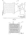
- the cooling device 50 includes a plurality of synthetic jet actuators/devices 10 such as are shown in FIGS. 1-3 , although it is recognized that the structure of the synthetic jet actuators included in the cooling device can vary from that of the synthetic jet actuator 10 shown in FIGS. 1-3 .
- the synthetic jet actuators 10 are arranged to form a synthetic jet stack 52, with the number of synthetic jet actuators 10 included in the stack 52 being determined based on a necessary flow volume output required to drive the cooling device. As shown in FIG. 5 , the orifice 22 of each of the synthetic jet actuators 10 in the stack 52 are aligned such that the jets of fluid emanating from each synthetic jet actuator 10 flows in the same direction.
- a manifold 54 is coupled to the stack of synthetic jet actuators 10 and is positioned to cover the plurality of orifices 22 of the synthetic jet actuators 10, such that the jets of fluid emanating from the synthetic jet actuators 10 are gathered by the manifold 54.
- the jets of fluid gathered by the manifold 54 are directed to an connecting pipe 56 (or similar component) that connects the manifold 54 to an air amplifier 58 of the cooling device 50, with the connecting pipe 56 being positioned relative to the air amplifier 58 such that the jets of fluid from the synthetic jet actuators 10 that are routed through the connecting pipe 56 are caused to exit an outlet 63 of the connecting pipe 56 at a throat 60 of a venturi section 62 of the air amplifier 58.
- the air amplifier 58 also includes an additional air intake 64 that is separate from the connecting pipe 56, with the air intake 64 being oriented perpendicular to the connecting pipe 56.
- An air outlet 66 is positioned opposite from air intake 64, on the other side of the venturi section 62, and can be positioned so as to be adjacent to a heat source 68 to be cooled, such that an amplified air flow having increased velocity and volume exiting the air outlet 66 is directed at the heat source 68.
- the heat source 68 could be in the form of a microelectronics circuit package and accordingly, the cooling device 50 could be configured as a micro-venturi device designed to fit within tight volume constraints imposed by the microelectronics circuit package.
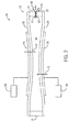
- FIG. 6 Operation of the hybrid coanda-venturi synthetic jet driven cooling device 50 - and the airflows generated thereby is generally illustrated in FIG. 6 .
- jets of fluid i.e., air
- the air is throttled through the connecting pipe 56 at high velocity and exits into the air amplifier 58 at the throat of the venturi section 62 as a primary air stream, indicated as 72.
- this primary air stream 72 that exits the connecting pipe 56 follows a path which is close to the surface 74 of the venturi section 62 - i.e., the primary air stream 72 adheres to the coanda profile - and is directed through the venturi 62 and toward the air outlet 66 of the air amplifier 58.
- the adhering of the primary air stream 72 close to the surface of the venturi creates a low pressure region in the center of the venturi, indicated as 74 which entrains the surrounding fluid/air entering the air amplifier through air intake to create a secondary air stream, generally indicated as 76, that flows in the direction of the primary air stream 72 - thereby creating a high volume flow of air into the primary air stream 72.
- the combination of the coanda and venturi effects serves to increase the volumetric flow rate from the synthetic jet device, with the combined flow of the primary air stream 72 and the surrounding air (i.e., secondary air stream 74) exiting the air outlet as a high volume, high velocity combined air flow, indicated as 78.
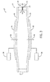
- a synthetic jet cooling device 80 is shown according to another embodiment of the invention.
- the synthetic jet cooling device 80 is similar in structure and operation to that of the synthetic jet cooling device 50 shown in FIGS. 4 and 6 , except that the stacked arrangement 52 of a plurality of individual synthetic jet actuators 10 in synthetic jet cooling device 50 is replaced by a single synthetic jet actuator 10 in synthetic jet cooling device 80. That is, it is recognized that an embodiment of the invention may be directed to a synthetic jet cooling device that incorporates only a single synthetic jet actuator rather than a plurality of synthetic jet actuators. In such an embodiment, the synthetic jet cooling device 80 may still take advantage of the coanda and venturi effects to increase the volumetric flow rate from the synthetic jet cooling device.
- embodiments of the invention thus provide a synthetic jet cooling device 50, 80 that is designed to take advantage of the coanda and venturi effects to increase the volumetric flow rate from the synthetic jet cooling device, with a resulting flowrate being as much as 15 - 20 times (for example) that of a flowrate generated by a similarly sized cooling device that is not designed to make use of the coanda and venturi effects (i.e., that relies just on the fluid jets generated by the synthetic jet actuators). Accordingly, the heat transfer rate that can be achieved by the synthetic jet cooling device 50, 80 is enhanced significantly.
- the size of the synthetic jet cooling device 50, 80 could be reduced - such that the cooling device could be implemented in an application having severe volume constraints imposed on the cooling system, such as might be encountered in cooling microelectronics circuit packages.
- the heat transfer rate could be increased dramatically.
- a synthetic jet driven cooling device includes at least one synthetic jet actuator configured to generate and project a series of fluid vortices through an orifice thereof and a manifold coupled to the at least one synthetic jet actuator so as to receive the series of fluid vortices from the orifice of the at least synthetic jet actuator, the series of fluid vortices from the at least one synthetic jet actuator generating a primary air stream.
- the synthetic jet driven cooling device also includes an air amplifier connected to the manifold by way of a connecting pipe so as to receive the primary air stream, with the air amplifier further comprising an air intake positioned at a first end of the air amplifier and having a first diameter, with the air intake being oriented perpendicular to an outlet of the connecting pipe, an air outlet positioned at a second end of the air amplifier opposite from the first end, and a venturi section positioned between the air intake and the air outlet and having a second diameter that is less than the first diameter.
- a low pressure region in a center of the venturi section entrains a surrounding air in through the air intake to generate a secondary air stream, the secondary air stream combining with the primary air stream to provide a combined air flow that flows through the venturi and exits the air outlet.
- a hybrid coanda-venturi cooling device includes at least one synthetic jet actuator configured to generate and project a series of fluid vortices out from an orifice thereof, a manifold coupled to the at least one synthetic jet actuator so as to receive the series of fluid vortices therefrom and generate a primary air stream, and an air amplifier connected to the manifold so as to receive the primary air stream, the air amplifier comprising a venturi section having a reduced cross-sectional area as compared to an air intake of the air amplifier.
- a coanda effect acting on the primary air stream as it enters the air amplifier and a venturi effect caused by the venturi section of the air amplifier causes a fluid surrounding the air intake to be entrained into the air intake to generate a secondary air stream, the secondary air stream combining with the primary air stream to provide a combined air flow that exits an air outlet of the air amplifier.
- a method of manufacturing a synthetic jet cooling device includes providing one or more synthetic jet actuators each configured to generate and project a series of fluid vortices out from an orifice thereof, coupling a manifold to the one or more synthetic jet actuators so as to receive the series of fluid vortices from the orifices of the synthetic jet actuators and generate a primary air stream therefrom, and connecting an air amplifier to the manifold by way of a connecting pipe so as to receive the primary air stream from the manifold, with the air amplifier comprising a venturi section having a reduced cross-sectional area as compared to an air intake of the air amplifier. Connection of the air amplifier to the synthetic jet stack generates an air flow output from the air amplifier having a higher velocity and volumetric flow rate than the primary air stream generated from the one or more synthetic jet actuators.
Landscapes
- Engineering & Computer Science (AREA)
- Mechanical Engineering (AREA)
- General Engineering & Computer Science (AREA)
- Physics & Mathematics (AREA)
- Fluid Mechanics (AREA)
- Chemical & Material Sciences (AREA)
- Combustion & Propulsion (AREA)
- Cooling Or The Like Of Electrical Apparatus (AREA)
- Jet Pumps And Other Pumps (AREA)
Abstract
Description
- Various embodiments of the invention relate generally to synthetic jet devices and, more particularly, to an apparatus for increasing the volumetric flow rate and heat transfer rate of synthetic jet devices.
- Synthetic jet actuators are a widely-used technology that generates a synthetic jet of fluid to influence the flow of that fluid over a surface to disperse heat away therefrom. A typical synthetic jet actuator comprises a housing defining an internal chamber. An orifice is present in a wall of the housing. The actuator further includes a mechanism in or about the housing for periodically changing the volume within the internal chamber so that a series of fluid vortices are generated and projected in an external environment out from the orifice of the housing. Examples of volume changing mechanisms may include, for example, a piston positioned in the jet housing to move fluid in and out of the orifice during reciprocation of the piston or a flexible diaphragm as a wall of the housing. The flexible diaphragm is typically actuated by a piezoelectric actuator or other appropriate means.
- Typically, a control system is used to create time-harmonic motion of the volume changing mechanism. As the mechanism decreases the chamber volume, fluid is ejected from the chamber through the orifice. As the fluid passes through the orifice, sharp edges of the orifice separate the flow to create vortex sheets that roll up into vortices. These vortices move away from the edges of the orifice under their own self-induced velocity. As the mechanism increases the chamber volume, ambient fluid is drawn into the chamber from large distances from the orifice. Since the vortices have already moved away from the edges of the orifice, they are not affected by the ambient fluid entering into the chamber. As the vortices travel away from the orifice, they synthesize a jet of fluid, i.e., a "synthetic jet."
- One drawback of typical synthetic jet devices is that they generate very low flow rates, so as to only provide for a corresponding low heat transfer rate. This low heat transfer rate can be problematic for systems and devices that require high rates of heat dissipation. Particularly in electronics packages, the rise in heat dissipation levels associated with increasingly powerful processing system has resulted in the need for improved cooling rates that typical synthetic jet devices may not be able to meet. In the microelectronics industry, for example, advances in technology have brought about an increase in transistor density and faster electronic chips, such that the heat flux that must be dissipated to maintain reasonable chip temperatures has also risen. While increasing the size and/or number of synthetic jet devices to meet these increased cooling requirements is possible, it is recognized that there are often severe volume constraints imposed on any cooling systems implemented to cool such electronic packages.
- Accordingly, there is a need for a system for cooling heat-producing devices in an efficient manner. There is a further need for such a system to have minimal space requirements and provide an increase in the cooling flow rate.
- Various embodiments of the invention thus address the aforementioned drawbacks by providing a synthetic jet driven cooling device that provides an increased cooling flow rate. The synthetic jet driven cooling device incorporates a package through which a fluid stream is routed and is subjected to coanda and venturi effects to increase a flow rate of the fluid stream so as to provide increased cooling capability.
- In accordance with one aspect of the invention, a synthetic jet driven cooling device includes at least one synthetic jet actuator configured to generate and project a series of fluid vortices through an orifice thereof and a manifold coupled to the at least one synthetic jet actuator so as to receive the series of fluid vortices from the orifice of the at least synthetic jet actuator, the series of fluid vortices from the at least one synthetic jet actuator generating a primary air stream. The synthetic jet driven cooling device also includes an air amplifier connected to the manifold by way of a connecting pipe so as to receive the primary air stream, with the air amplifier further comprising an air intake positioned at a first end of the air amplifier and having a first diameter, with the air intake being oriented perpendicular to an outlet of the connecting pipe, an air outlet positioned at a second end of the air amplifier opposite from the first end, and a venturi section positioned between the air intake and the air outlet and having a second diameter that is less than the first diameter. A low pressure region in a center of the venturi section entrains a surrounding air in through the air intake to generate a secondary air stream, the secondary air stream combining with the primary air stream to provide a combined air flow that flows through the venturi and exits the air outlet.
- In accordance with another aspect of the invention, a hybrid coanda-venturi cooling device includes at least one synthetic jet actuator configured to generate and project a series of fluid vortices out from an orifice thereof, a manifold coupled to the at least one synthetic jet actuator so as to receive the series of fluid vortices therefrom and generate a primary air stream, and an air amplifier connected to the manifold so as to receive the primary air stream, the air amplifier comprising a venturi section having a reduced cross-sectional area as compared to an air intake of the air amplifier. A coanda effect acting on the primary air stream as it enters the air amplifier and a venturi effect caused by the venturi section of the air amplifier causes a fluid surrounding the air intake to be entrained into the air intake to generate a secondary air stream, the secondary air stream combining with the primary air stream to provide a combined air flow that exits an air outlet of the air amplifier.
- In accordance with yet another aspect of the invention, a method of manufacturing a synthetic jet cooling device includes providing one or more synthetic jet actuators each configured to generate and project a series of fluid vortices out from an orifice thereof, coupling a manifold to the one or more synthetic jet actuators so as to receive the series of fluid vortices from the orifices of the synthetic jet actuators and generate a primary air stream therefrom, and connecting an air amplifier to the manifold by way of a connecting pipe so as to receive the primary air stream from the manifold, with the air amplifier comprising a venturi section having a reduced cross-sectional area as compared to an air intake of the air amplifier. Connection of the air amplifier to the synthetic jet stack generates an air flow output from the air amplifier having a higher velocity and volumetric flow rate than the primary air stream generated from the one or more synthetic jet actuators.
- Various advantages and features will be more readily understood from the following detailed description of preferred embodiments of the invention that is provided in connection with the accompanying drawings, in which:
-
FIG. 1 is a cross-section of a synthetic jet actuator with a control system. -
FIG. 2 is a cross-section of the synthetic jet actuator ofFIG. 1 depicting the jet as the control system causes the plates to travel inward, toward the orifice. -
FIG. 3 is a cross-section of the synthetic jet actuator ofFIG. 1 depicting the jet as the control system causes the plates to travel outward, away from the orifice. -
FIGS. 4 and 5 are block schematic diagrams of a synthetic jet driven cooling device according to an embodiment of the invention. -
FIG. 6 is a block schematic diagram illustrating fluid flows generated by the synthetic jet driven cooling device ofFIGS. 4 and 5 . -
FIG. 7 is a block schematic diagram of a synthetic jet driven cooling device according to an embodiment of the invention. - Referring to
FIGS. 1-3 , a synthetic jet actuator ordevice 10, and the operation thereof, that may be used with embodiments of the invention is shown for purposes of describing the general operation of a synthetic jet actuator. Thesynthetic jet actuator 10 includes ahousing 12 defining and enclosing aninternal chamber 14. Thehousing 12 andchamber 14 can take virtually any geometric configuration, such as a disc , an oval, a square, a rectangle, an ellipse, and the like, depending on the application, but for purposes of discussion and understanding, thehousing 12 is shown in cross-section inFIG. 1 to have a continuous outer bounding surface orwall 16 and a pair ofplates 18, 20 (i.e., top and bottom plates) arranged parallel to one another on either side of thewall 16 so as to define thechamber 14, with one or both of the plates being flexible to an extent to permit displacement thereof inwardly and outwardly relative to thechamber 14. Thewall 16 has one ormore orifices 22 of any geometric shape that place theinternal chamber 14 in fluid communication with a surrounding external environment having ambient fluid (e.g., air), with the orifice(s) 22 being positioned in order to direct fluid emitting therefrom at a desired location and at an object (not shown) positioned proximate to or around thesynthetic jet actuator 10. - Attached to at least one of the
plates FIGS. 1-3 , are one or more actuator elements, micromechanical devices, orpiezomotive devices actuator elements power source 28, and undergo mechanical stress and/or strain responsive to the charge. The stress/strain ofpiezoelectric elements plates piezoelectric elements plates synthetic jet stream 30 expelled from thesynthetic jet actuator 10. - In embodiments of the invention,
actuators power source 28 is configured to activateactuators power source 28 may be configured to provide a rapidly alternating electrostatic voltage toactuators flex plates actuators - The operation of the
synthetic jet actuator 10 is described with reference toFIGS. 2 and3 .FIG. 2 depicts thesynthetic jet actuator 10 as theplates power source 28 to move inward into thechamber 14, as depicted byarrow 31. Thechamber 14 has its volume decreased and fluid is ejected through theorifice 22. As the fluid exits thechamber 14 through theorifice 22, the flow separates at edges of theorifice 22 and createsvortex sheets 32 which roll intovortices 34 and begin to move away from theorifice edges 30 in the direction indicated byarrow 36.FIG. 3 depicts thesynthetic jet actuator 10 as theplates chamber 14, as depicted byarrow 38. Thechamber 14 has its volume increased andambient fluid 39 rushes into thechamber 14 as depicted by the set of arrows 40. Theplates control system 28 so that when theplates chamber 14, thevortices 34 are already removed from the orifice edges and thus are not affected by theambient fluid 39 being drawn into thechamber 14. Meanwhile, a jet ofambient fluid 39 is synthesized by thevortices 34 creating strong entrainment of ambient fluid drawn from large distances away from theorifice 22. - Referring now to
FIGS. 4 and 5 , a hybrid coanda-venturi synthetic jet drivencooling device 50 is shown according to an embodiment of the invention. Thecooling device 50 includes a plurality of synthetic jet actuators/devices 10 such as are shown inFIGS. 1-3 , although it is recognized that the structure of the synthetic jet actuators included in the cooling device can vary from that of thesynthetic jet actuator 10 shown inFIGS. 1-3 . Thesynthetic jet actuators 10 are arranged to form asynthetic jet stack 52, with the number ofsynthetic jet actuators 10 included in thestack 52 being determined based on a necessary flow volume output required to drive the cooling device. As shown inFIG. 5 , theorifice 22 of each of thesynthetic jet actuators 10 in thestack 52 are aligned such that the jets of fluid emanating from eachsynthetic jet actuator 10 flows in the same direction. - Referring again to
FIG. 4 , amanifold 54 is coupled to the stack ofsynthetic jet actuators 10 and is positioned to cover the plurality oforifices 22 of thesynthetic jet actuators 10, such that the jets of fluid emanating from thesynthetic jet actuators 10 are gathered by themanifold 54. The jets of fluid gathered by themanifold 54 are directed to an connecting pipe 56 (or similar component) that connects themanifold 54 to anair amplifier 58 of thecooling device 50, with the connectingpipe 56 being positioned relative to theair amplifier 58 such that the jets of fluid from thesynthetic jet actuators 10 that are routed through the connectingpipe 56 are caused to exit anoutlet 63 of the connectingpipe 56 at athroat 60 of aventuri section 62 of theair amplifier 58. - As shown in
FIG. 4 , theair amplifier 58 also includes anadditional air intake 64 that is separate from the connectingpipe 56, with theair intake 64 being oriented perpendicular to the connectingpipe 56. Anair outlet 66 is positioned opposite fromair intake 64, on the other side of theventuri section 62, and can be positioned so as to be adjacent to aheat source 68 to be cooled, such that an amplified air flow having increased velocity and volume exiting theair outlet 66 is directed at theheat source 68. According to one embodiment, theheat source 68 could be in the form of a microelectronics circuit package and accordingly, thecooling device 50 could be configured as a micro-venturi device designed to fit within tight volume constraints imposed by the microelectronics circuit package. - Operation of the hybrid coanda-venturi synthetic jet driven cooling device 50 - and the airflows generated thereby is generally illustrated in
FIG. 6 . In operation of thecooling device 50, jets of fluid (i.e., air) generated by thesynthetic jet actuators 10, indicated as 70, are gathered by the manifold 54 and compressed to flow through the connectingpipe 56. The air is throttled through the connectingpipe 56 at high velocity and exits into theair amplifier 58 at the throat of theventuri section 62 as a primary air stream, indicated as 72. Due to the coanda effect, thisprimary air stream 72 that exits the connectingpipe 56 follows a path which is close to thesurface 74 of the venturi section 62 - i.e., theprimary air stream 72 adheres to the coanda profile - and is directed through theventuri 62 and toward theair outlet 66 of theair amplifier 58. The adhering of theprimary air stream 72 close to the surface of the venturi creates a low pressure region in the center of the venturi, indicated as 74 which entrains the surrounding fluid/air entering the air amplifier through air intake to create a secondary air stream, generally indicated as 76, that flows in the direction of the primary air stream 72 - thereby creating a high volume flow of air into theprimary air stream 72. The combination of the coanda and venturi effects serves to increase the volumetric flow rate from the synthetic jet device, with the combined flow of theprimary air stream 72 and the surrounding air (i.e., secondary air stream 74) exiting the air outlet as a high volume, high velocity combined air flow, indicated as 78. - Referring now to
FIG. 7 , a syntheticjet cooling device 80 is shown according to another embodiment of the invention. The syntheticjet cooling device 80 is similar in structure and operation to that of the syntheticjet cooling device 50 shown inFIGS. 4 and6 , except that the stackedarrangement 52 of a plurality of individualsynthetic jet actuators 10 in syntheticjet cooling device 50 is replaced by a singlesynthetic jet actuator 10 in syntheticjet cooling device 80. That is, it is recognized that an embodiment of the invention may be directed to a synthetic jet cooling device that incorporates only a single synthetic jet actuator rather than a plurality of synthetic jet actuators. In such an embodiment, the syntheticjet cooling device 80 may still take advantage of the coanda and venturi effects to increase the volumetric flow rate from the synthetic jet cooling device. - Beneficially, embodiments of the invention thus provide a synthetic
jet cooling device jet cooling device jet cooling device cooling device - Therefore, according to one embodiment of the invention, a synthetic jet driven cooling device includes at least one synthetic jet actuator configured to generate and project a series of fluid vortices through an orifice thereof and a manifold coupled to the at least one synthetic jet actuator so as to receive the series of fluid vortices from the orifice of the at least synthetic jet actuator, the series of fluid vortices from the at least one synthetic jet actuator generating a primary air stream. The synthetic jet driven cooling device also includes an air amplifier connected to the manifold by way of a connecting pipe so as to receive the primary air stream, with the air amplifier further comprising an air intake positioned at a first end of the air amplifier and having a first diameter, with the air intake being oriented perpendicular to an outlet of the connecting pipe, an air outlet positioned at a second end of the air amplifier opposite from the first end, and a venturi section positioned between the air intake and the air outlet and having a second diameter that is less than the first diameter. A low pressure region in a center of the venturi section entrains a surrounding air in through the air intake to generate a secondary air stream, the secondary air stream combining with the primary air stream to provide a combined air flow that flows through the venturi and exits the air outlet.
- According to another embodiment of the invention, a hybrid coanda-venturi cooling device includes at least one synthetic jet actuator configured to generate and project a series of fluid vortices out from an orifice thereof, a manifold coupled to the at least one synthetic jet actuator so as to receive the series of fluid vortices therefrom and generate a primary air stream, and an air amplifier connected to the manifold so as to receive the primary air stream, the air amplifier comprising a venturi section having a reduced cross-sectional area as compared to an air intake of the air amplifier. A coanda effect acting on the primary air stream as it enters the air amplifier and a venturi effect caused by the venturi section of the air amplifier causes a fluid surrounding the air intake to be entrained into the air intake to generate a secondary air stream, the secondary air stream combining with the primary air stream to provide a combined air flow that exits an air outlet of the air amplifier.
- According to yet another embodiment of the invention, a method of manufacturing a synthetic jet cooling device includes providing one or more synthetic jet actuators each configured to generate and project a series of fluid vortices out from an orifice thereof, coupling a manifold to the one or more synthetic jet actuators so as to receive the series of fluid vortices from the orifices of the synthetic jet actuators and generate a primary air stream therefrom, and connecting an air amplifier to the manifold by way of a connecting pipe so as to receive the primary air stream from the manifold, with the air amplifier comprising a venturi section having a reduced cross-sectional area as compared to an air intake of the air amplifier. Connection of the air amplifier to the synthetic jet stack generates an air flow output from the air amplifier having a higher velocity and volumetric flow rate than the primary air stream generated from the one or more synthetic jet actuators.
- While the invention has been described in detail in connection with only a limited number of embodiments, it should be readily understood that the invention is not limited to such disclosed embodiments. Rather, the invention can be modified to incorporate any number of variations, alterations, substitutions or equivalent arrangements not heretofore described, but which are commensurate with the spirit and scope of the invention. Additionally, while various embodiments of the invention have been described, it is to be understood that aspects of the invention may include only some of the described embodiments. Accordingly, the invention is not to be seen as limited by the foregoing description, but is only limited by the scope of the appended claims.
- Various aspects and embodiments of the present invention are defined by the following numbered clauses:
- 1. A synthetic jet driven cooling device comprising:
- at least one synthetic jet actuator configured to generate and project a series of fluid vortices, each of the at least one synthetic jet actuators comprising an orifice through which the series of fluid vortices are projected;
- a manifold coupled to the at least one synthetic jet actuator so as to receive the series of fluid vortices from the orifice of the at least synthetic jet actuator, the series of fluid vortices from the at least one synthetic jet actuator generating a primary air stream;
- an air amplifier connected to the manifold by way of a connecting pipe so as to receive the primary air stream, the air amplifier comprising:
- an air intake positioned at a first end of the air amplifier and having a first diameter, with the air intake being oriented perpendicular to an outlet of the connecting pipe;
- an air outlet positioned at a second end of the air amplifier opposite from the first end; and
- a venturi section positioned between the air intake and the air outlet and having a second diameter that is less than the first diameter;
- wherein a low pressure region in a center of the venturi section entrains a surrounding air in through the air intake to generate a secondary air stream, the secondary air stream combining with the primary air stream to provide a combined air flow that flows through the venturi and exits the air outlet.
- 2. The cooling device of clause 1 wherein the outlet of the connecting pipe is coupled to the air amplifier at a throat of the venturi section that tapers the air amplifier down from the first diameter of the air intake to the second diameter of the venturi section.
- 3. The cooling device of any preceding clause wherein, upon exiting the connecting pipe, the primary air stream is caused to flow in proximity to a surface of the venturi section of the air amplifier due to the coanda effect.
- 4. The cooling device of any preceding clause wherein the venturi section of the air amplifier causes a velocity of the primary air stream to increase as it passes therethrough due to the venturi effect, thereby also forming the low pressure region in the center of the venturi section.
- 5. The cooling device of any preceding clause wherein the combined air flow that exits the air outlet of the air amplifier has a higher velocity and volumetric flow rate than the primary air stream generated from the series of fluid vortices from the at least one synthetic jet actuator.
- 6. The cooling device of any preceding clause wherein the volumetric flow rate of the combined air stream is 15 to 20 times greater than that of the primary air stream.
- 7. The cooling device of any preceding clause wherein the air outlet of the air amplifier is positioned adjacent a heat source, such that the combined air flow provides cooling to the heat source.
- 8. The cooling device of any preceding clause wherein the air amplifier comprises a micro-venturi device configured to fit within volume constraints imposed by a microelectronics circuit package that is being cooled.
- 9. The cooling device of any preceding clause wherein the at least one synthetic jet actuator comprises a plurality of synthetic jet actuators arranged in a stacked configuration, with the orifice of each of the plurality of synthetic jet actuators being aligned with other orifices such that the series of fluid vortices projected from each synthetic jet actuator is directed into the manifold.
- 10. The cooling device of any preceding clause wherein each of the at least one synthetic jet actuators comprises:
- a first plate;
- a second plate spaced apart from the first plate and arranged parallelly thereto;
- a wall structure coupled to and positioned between the first and second plates to form a chamber and including the orifice therein; and
- an actuator element coupled to at least one of the first and second plates to selectively cause deflection thereof, thereby changing a volume within the chamber so that the series of fluid vortices are generated and projected out from the orifice of the wall structure.
- 11. A hybrid coanda-venturi cooling device comprising:
- at least one synthetic jet actuator, each of the at least one synthetic jet actuators configured to generate and project a series of fluid vortices out from an orifice thereof;
- a manifold coupled to the at least one synthetic jet actuator so as to receive the series of fluid vortices therefrom, the series of fluid vortices from the at least one synthetic jet actuator generating a primary air stream;
- an air amplifier connected to the manifold so as to receive the primary air stream, the air amplifier comprising a venturi section having a reduced cross-sectional area as compared to an air intake of the air amplifier;
- wherein a coanda effect acting on the primary air stream as it enters the air amplifier and a venturi effect caused by the venturi section of the air amplifier causes a fluid surrounding the air intake to be entrained into the air intake to generate a secondary air stream, the secondary air stream combining with the primary air stream to provide a combined air flow that exits an air outlet of the air amplifier.
- 12. The cooling device of any preceding clause wherein the primary air stream enters the air amplifier in a direction generally perpendicular to the air intake of the air amplifier and at a throat of the venturi section.
- 13. The cooling device of any preceding clause wherein the throat of the venturi section tapers the air amplifier down from a first diameter at the air intake to a second diameter of the venturi section that is less than the first diameter.
- 14. The cooling device of any preceding clause wherein the coanda effect acting on the primary air stream as it enters the air amplifier causes the primary air stream to flow in proximity to a surface of the venturi section of the air amplifier.
- 15. The cooling device of any preceding clause wherein the venturi section of the air amplifier causes a velocity of the primary air stream to increase as it passes therethrough due to the venturi effect, thereby also forming a low pressure region in a center of the venturi section that causes the fluid surrounding the air intake to be entrained into the air intake.
- 16. The cooling device of any preceding clause wherein the combined air flow that exits the air outlet of the air amplifier has a higher velocity and volumetric flow rate than the primary air stream generated from the series of fluid vortices from the at least one synthetic jet actuator.
- 17. The cooling device of any preceding clause wherein the at least one synthetic jet actuator comprises a plurality of synthetic jet actuators arranged in a stacked configuration, with the orifice of each of the plurality of synthetic jet actuators being aligned with other orifices such that the series of fluid vortices projected from each synthetic jet actuator is directed into the manifold.
- 18. A method of manufacturing a synthetic jet cooling device comprising:
- providing one or more synthetic jet actuators each configured to generate and project a series of fluid vortices out from an orifice thereof;
- coupling a manifold to the one or more synthetic jet actuators so as to receive the series of fluid vortices from the orifices of the synthetic jet actuators, the series of fluid vortices from the one or more synthetic jet actuators generating a primary air stream;
- connecting an air amplifier to the manifold by way of a connecting pipe so as to receive the primary air stream from the manifold, the air amplifier comprising a venturi section having a reduced cross-sectional area as compared to an air intake of the air amplifier;
- wherein connection of the air amplifier to the synthetic jet stack generates an air flow output from the air amplifier having a higher velocity and volumetric flow rate than the primary air stream generated from the one or more synthetic jet actuators.
- 19. The method of any preceding clause wherein a coanda effect acting on the primary air stream as it enters the air amplifier and a venturi effect caused by the venturi section of the air amplifier causes a fluid surrounding the air intake to be entrained into the air intake to generate a secondary air stream, the secondary air stream combining with the primary air stream to provide the air flow output that exits an air outlet of the air amplifier.
- 20. The cooling system of any preceding clause wherein connecting the air amplifier to the manifold comprises connecting an outlet of the connecting pipe to the air amplifier at a throat of the venturi section, with the outlet of the connecting pipe being oriented perpendicular to the air intake of the air amplifier, such that the primary air stream is subject to the coanda effect and venturi effect.
- 21. The cooling system of any preceding clause wherein the one or more synthetic jet actuators comprises a plurality of synthetic jet actuators, and wherein the method further comprises arranging the plurality of synthetic jet actuators into a synthetic jet stack and such that the orifices of the plurality of synthetic jet actuators are aligned.
Claims (15)
- A synthetic jet driven cooling device (50) comprising:a plurality of synthetic jet actuators (10) arranged in a stacked configuration, each of the plurality of synthetic jet actuators configured to generate and project a series of fluid vortices out from an orifice thereof;a manifold (54) coupled to the plurality of synthetic jet actuators (10) so as to receive the series of fluid vortices from the orifices of the synthetic jet actuators, the series of fluid vortices from the plurality of synthetic jet actuators (10) generating a primary air stream;an air amplifier (58) connected to the manifold (54) by way of a connecting pipe (56) so as to receive the primary air stream, the air amplifier (58) comprising:an air intake (64) positioned at a first end of the air amplifier (58) and having a first diameter, with the air intake (64) being oriented perpendicular to an outlet of the connecting pipe (56);an air outlet (66) positioned at a second end of the air amplifier opposite from the first end; anda venturi section (62) positioned between the air intake (64) and the air outlet (66) and having a second diameter that is less than the first diameter;wherein a low pressure region in a center of the venturi section (62) entrains a surrounding air in through the air intake to generate a secondary air stream, the secondary air stream combining with the primary air stream to provide a combined air flow that flows through the venturi (62) and exits the air outlet (66).
- The cooling device (50) of claim 1 wherein the outlet of the connecting pipe (56) is coupled to the air amplifier (58) at a throat of the venturi section (62) that tapers the air amplifier down from the first diameter of the air intake to the second diameter of the venturi section (62).
- The cooling device (50) of any preceding claim wherein, upon exiting the connecting pipe (56), the primary air stream is caused to flow in proximity to a surface of the venturi section (62) of the air amplifier (58) due to the coanda effect.
- The cooling device (50) of any preceding claim wherein the venturi section (62) of the air amplifier (58) causes a velocity of the primary air stream to increase as it passes therethrough due to the venturi effect, thereby also forming the low pressure region in the center of the venturi section (62).
- The cooling device (50) of any preceding claim wherein the combined air flow that exits the air outlet (66) of the air amplifier (58) has a higher velocity and volumetric flow rate than the primary air stream generated from the series of fluid vortices from the plurality of synthetic jet actuators (10).
- The cooling device (50) of claim 5 wherein the volumetric flow rate of the combined air stream is 15 to 20 times greater than that of the primary air stream.
- The cooling device (50) of any preceding claim wherein the air outlet (66) of the air amplifier (58) is positioned adjacent a heat source (68), such that the combined air flow provides cooling to the heat source (68).
- The cooling device (50) of claim 7 wherein the heat source (68) comprises a microelectronics circuit package.
- The cooling device (50) of claim 8 wherein the air amplifier (58) comprises a micro-venturi device configured to fit within volume constraints imposed by the microelectronics circuit package.
- The cooling device (50) of any preceding claim wherein each of the plurality of synthetic jet actuators (10) comprises:a first plate;a second plate spaced apart from the first plate and arranged parallelly thereto;a wall structure coupled to and positioned between the first and second plates to form a chamber and including the orifice therein; andan actuator element coupled to at least one of the first and second plates to selectively cause deflection thereof, thereby changing a volume within the chamber so that the series of fluid vortices are generated and projected out from the orifice of the wall structure.
- A hybrid coanda-venturi cooling device (50) comprising:a plurality of synthetic jet actuators (10) arranged in a stacked configuration, each of the plurality of synthetic jet actuators configured to generate and project a series of fluid vortices out from an orifice thereof;a manifold (54) coupled to the plurality of synthetic jet actuators so as to receive the series of fluid vortices from the orifices of the synthetic jet actuators, the series of fluid vortices from the plurality of synthetic jet actuators generating a primary air stream;an air amplifier (58) connected to the manifold so as to receive the primary air stream, the air amplifier comprising a venturi section having a reduced cross-sectional area as compared to an air intake of the air amplifier;wherein a coanda effect acting on the primary air stream as it enters the air amplifier and a venturi effect caused by the venturi section (62) of the air amplifier causes a fluid surrounding the air intake to be entrained into the air intake to generate a secondary air stream, the secondary air stream combining with the primary air stream to provide a combined air flow that exits an air outlet of the air amplifier.
- The cooling device (50) of claim 11 wherein the primary air stream enters the air amplifier in a direction generally perpendicular to the air intake of the air amplifier (58) and at a throat of the venturi section (62).
- The cooling device (50) of claim 11 or claim 12 wherein each of the plurality of synthetic jet actuators (10) comprises:a first plate;a second plate spaced apart from the first plate and arranged parallelly thereto;a wall structure coupled to and positioned between the first and second plates to form a chamber and including the orifice therein; andan actuator element coupled to at least one of the first and second plates to selectively cause deflection thereof, thereby changing a volume within the chamber so that the series of fluid vortices are generated and projected out from the orifice of the wall structure.
- A method of manufacturing a synthetic jet cooling device (50) comprising:providing a plurality of synthetic jet actuators (10) each configured to generate and project a series of fluid vortices out from an orifice thereof;arranging the plurality of synthetic jet actuators into a synthetic jet stack and such that the orifices of the plurality of synthetic jet actuators are aligned;coupling a manifold (54) to the plurality of synthetic jet actuators (10) so as to receive the series of fluid vortices from the orifices of the synthetic jet actuators, the series of fluid vortices from the plurality of synthetic jet actuators generating a primary air stream;connecting an air amplifier (58) to the manifold (54) by way of a connecting pipe (56) so as to receive the primary air stream from the manifold, the air amplifier comprising a venturi section having a reduced cross-sectional area as compared to an air intake of the air amplifier;wherein connection of the air amplifier (58) to the synthetic jet stack generates an air flow output from the air amplifier (58) having a higher velocity and volumetric flow rate than the primary air stream generated from the plurality of synthetic jet actuators (10).
- The cooling system of claim 14 wherein connecting the air amplifier (58) to the manifold (54) comprises connecting an outlet (66) of the connecting pipe (56) to the air amplifier (58) at a throat of the venturi section (62), with the outlet (66) of the connecting pipe (56) being oriented perpendicular to the air intake (64) of the air amplifier, such that the primary air stream is subject to the coanda effect and venturi effect.
Applications Claiming Priority (2)
| Application Number | Priority Date | Filing Date | Title |
|---|---|---|---|
| US201361783065P | 2013-03-14 | 2013-03-14 | |
| US13/871,353 US9976762B2 (en) | 2013-03-14 | 2013-04-26 | Synthetic jet driven cooling device with increased volumetric flow |
Publications (2)
| Publication Number | Publication Date |
|---|---|
| EP2778415A1 true EP2778415A1 (en) | 2014-09-17 |
| EP2778415B1 EP2778415B1 (en) | 2016-06-01 |
Family
ID=50272368
Family Applications (1)
| Application Number | Title | Priority Date | Filing Date |
|---|---|---|---|
| EP14158786.5A Not-in-force EP2778415B1 (en) | 2013-03-14 | 2014-03-11 | Synthetic jet driven cooling device with increased volumetric flow |
Country Status (6)
| Country | Link |
|---|---|
| US (1) | US9976762B2 (en) |
| EP (1) | EP2778415B1 (en) |
| JP (1) | JP6367578B2 (en) |
| KR (1) | KR20140113410A (en) |
| CN (1) | CN104053340B (en) |
| TW (1) | TWI628367B (en) |
Cited By (3)
| Publication number | Priority date | Publication date | Assignee | Title |
|---|---|---|---|---|
| FR3047730A1 (en) * | 2016-02-11 | 2017-08-18 | Bosch Gmbh Robert | MICROMECHANICAL DEVICE AND METHOD FOR PUMPING A FLUID |
| EP3225925A1 (en) * | 2016-03-31 | 2017-10-04 | Mitsubishi Electric Corporation | Heat exchanger unit with synthetic jet flow device |
| EP3306091A1 (en) * | 2016-10-10 | 2018-04-11 | General Electric Company | Compressor with dual bimorph synthetic jet assemblies |
Families Citing this family (13)
| Publication number | Priority date | Publication date | Assignee | Title |
|---|---|---|---|---|
| CN109277009A (en) * | 2011-12-05 | 2019-01-29 | 斯蒂芬·M·萨菲奥蒂 | System and method for producing a homogeneous oilfield gel |
| EP2888479B1 (en) * | 2012-07-05 | 2021-03-03 | 3M Innovative Properties Company | Systems and methods for supplying reduced pressure using a disc pump with electrostatic actuation |
| KR20160031717A (en) * | 2014-09-15 | 2016-03-23 | 삼성전자주식회사 | Full front blowing type air conditioner |
| KR20160031715A (en) * | 2014-09-15 | 2016-03-23 | 삼성전자주식회사 | Air current changeable full front blowing type air conditioner |
| US9629233B2 (en) * | 2015-06-08 | 2017-04-18 | Qualcomm Incorporated | Techniques for implementing a synthetic jet to cool a device |
| CN107559270B (en) * | 2017-09-08 | 2023-11-14 | 浙江大学 | Synthetic jet plate turbulence drag reduction device |
| CN108008796A (en) * | 2018-01-02 | 2018-05-08 | 北京涌阔科技有限公司 | A kind of energy-saving cool-down structure of central processing unit |
| CN108393199B (en) * | 2018-04-27 | 2024-05-10 | 清华大学 | Synthetic jet device |
| CN110999869A (en) * | 2019-12-18 | 2020-04-14 | 吉林省养蜂科学研究所(吉林省蜂产品质量管理监督站、吉林省蜜蜂遗传资源基因保护中心) | Ventilation adjusting device and ventilation adjusting method for outdoor bumblebee pollination box |
| KR20220117924A (en) * | 2019-12-29 | 2022-08-24 | 액타시스 인코포레이티드 | Temperature Control Using Active Flow Control Actuators |
| WO2021216462A1 (en) * | 2020-04-20 | 2021-10-28 | Lam Research Corporation | Enhanced closed loop gas based heat exchange |
| CN111623505B (en) * | 2020-05-25 | 2022-03-15 | 太原理工大学 | A self-excited oscillating jet type mixing heat exchange air outlet device |
| CN115981010A (en) * | 2023-02-21 | 2023-04-18 | 维沃移动通信有限公司 | Wearable device |
Citations (4)
| Publication number | Priority date | Publication date | Assignee | Title |
|---|---|---|---|---|
| JPS62264120A (en) * | 1986-05-07 | 1987-11-17 | Kiyoyuki Horii | Transportation of solid particle |
| WO2010035198A1 (en) * | 2008-09-26 | 2010-04-01 | Koninklijke Philips Electronics, N.V. | Jet eductor pump |
| US8006961B1 (en) * | 2007-05-30 | 2011-08-30 | Alex Rutstein | Apparatus and method for treating process fluid |
| US20120170216A1 (en) * | 2011-01-04 | 2012-07-05 | General Electric Company | Synthetic jet packaging |
Family Cites Families (47)
| Publication number | Priority date | Publication date | Assignee | Title |
|---|---|---|---|---|
| GB1551915A (en) | 1975-11-12 | 1979-09-05 | British Petroleum Co | Burner element |
| CN1028053C (en) | 1989-11-01 | 1995-03-29 | 赵谦 | Pneumatic jet pump for extracting liquid |
| US5347809A (en) * | 1993-03-12 | 1994-09-20 | Caterpillar Inc. | Apparatus and method for removing particulate from an exhaust gas filter |
| US6457654B1 (en) * | 1995-06-12 | 2002-10-01 | Georgia Tech Research Corporation | Micromachined synthetic jet actuators and applications thereof |
| JPH09287451A (en) * | 1996-04-22 | 1997-11-04 | Aisin Chem Co Ltd | Radiator cooling system |
| US7354873B2 (en) * | 1998-02-05 | 2008-04-08 | Asm Japan K.K. | Method for forming insulation film |
| US6498316B1 (en) * | 1999-10-25 | 2002-12-24 | Thermal Dynamics Corporation | Plasma torch and method for underwater cutting |
| US6644598B2 (en) * | 2001-03-10 | 2003-11-11 | Georgia Tech Research Corporation | Modification of fluid flow about bodies and surfaces through virtual aero-shaping of airfoils with synthetic jet actuators |
| JP2003023283A (en) | 2001-07-09 | 2003-01-24 | Hitachi Ltd | Electronic component cooling system |
| US6588497B1 (en) * | 2002-04-19 | 2003-07-08 | Georgia Tech Research Corporation | System and method for thermal management by synthetic jet ejector channel cooling techniques |
| US6678157B1 (en) * | 2002-09-17 | 2004-01-13 | Sun Microsystems, Inc. | Electronics assembly with cooling arrangement |
| JP3971991B2 (en) * | 2002-12-03 | 2007-09-05 | 株式会社日立産機システム | Air shower device |
| US7027300B2 (en) | 2003-09-16 | 2006-04-11 | Mobility Electronics, Inc. | Compact electronics plenum |
| KR100519970B1 (en) * | 2003-10-07 | 2005-10-13 | 삼성전자주식회사 | Valveless Micro Air Delivery Device |
| JP4887652B2 (en) | 2005-04-21 | 2012-02-29 | ソニー株式会社 | Jet generator and electronic device |
| EP1722412B1 (en) * | 2005-05-02 | 2012-08-29 | Sony Corporation | Jet generator and electronic device |
| US7823839B2 (en) * | 2005-10-31 | 2010-11-02 | Georgia Tech Research Corporation | Airfoil performance modification using synthetic jet actuators |
| CN101568732B (en) * | 2006-12-15 | 2015-10-07 | 皇家飞利浦电子股份有限公司 | Pulsating fluid cooling with frequency control |
| US7955650B2 (en) * | 2007-06-07 | 2011-06-07 | Asm Japan K.K. | Method for forming dielectric film using porogen gas |
| US20080310110A1 (en) * | 2007-06-12 | 2008-12-18 | General Electric Company | System and method for mounting a cooling device and method of fabrication |
| US8434909B2 (en) * | 2007-10-09 | 2013-05-07 | Flex Lighting Ii, Llc | Light emitting display with light mixing within a film |
| US7957140B2 (en) * | 2007-12-31 | 2011-06-07 | Intel Corporation | Air mover for device surface cooling |
| JP5182993B2 (en) * | 2008-03-31 | 2013-04-17 | 株式会社半導体エネルギー研究所 | Display device and manufacturing method thereof |
| KR101555365B1 (en) | 2008-06-27 | 2015-09-23 | 엘지전자 주식회사 | Cooling device for electronic devices |
| CN102105980B (en) * | 2008-07-25 | 2013-07-24 | 皇家飞利浦电子股份有限公司 | A cooling device for cooling a semiconductor die |
| IT1391343B1 (en) | 2008-08-07 | 2011-12-05 | Pavan S R L | EQUIPMENT AND PROCEDURE FOR THE TREATMENT OF A FOOD AND ITS RELATED PRODUCT FOR THE TREATMENT OF A FOOD PRODUCT |
| US8752775B2 (en) * | 2008-08-26 | 2014-06-17 | General Electric Company | Method and apparatus for reducing acoustic noise in a synthetic jet |
| US8006917B2 (en) * | 2008-08-26 | 2011-08-30 | General Electric Company | Method and apparatus for reducing acoustic noise in a synthetic jet |
| US8418934B2 (en) * | 2008-08-26 | 2013-04-16 | General Electric Company | System and method for miniaturization of synthetic jets |
| WO2010056984A2 (en) * | 2008-11-14 | 2010-05-20 | The Regents Of The University Of Michigan | Acoustical fluid control mechanism |
| FR2942367B1 (en) | 2009-02-13 | 2011-04-08 | Peugeot Citroen Automobiles Sa | PROTECTIVE COVER FOR PIECE (S) WITH SUCTION EFFECT AIR-PIPING ELEMENTS (S) AND CASING THEREFOR |
| FR2943892B1 (en) * | 2009-04-07 | 2011-08-05 | Commissariat Energie Atomique | METHOD OF MEMBRANE PERMEABILIZATION OF BIOLOGICAL CELLS BY USE OF A PULSE ELECTRIC FIELD |
| US8496049B2 (en) * | 2009-04-09 | 2013-07-30 | General Electric Company | Heat sinks with distributed and integrated jet cooling |
| US9102217B2 (en) * | 2009-10-28 | 2015-08-11 | GM Global Technology Operations LLC | Air curtain |
| DE102009047083C5 (en) | 2009-11-24 | 2013-09-12 | J. Schmalz Gmbh | Compressed air operated vacuum generator or vacuum gripper |
| US8881994B2 (en) | 2009-12-16 | 2014-11-11 | General Electric Company | Low frequency synthetic jet actuator and method of manufacturing thereof |
| US8695686B2 (en) | 2010-01-07 | 2014-04-15 | General Electric Company | Method and apparatus for removing heat from electronic devices using synthetic jets |
| JP5868015B2 (en) | 2010-04-14 | 2016-02-24 | ゼネラル・エレクトリック・カンパニイ | Chassis with distributed jet cooling |
| US9028123B2 (en) * | 2010-04-16 | 2015-05-12 | Flex Lighting Ii, Llc | Display illumination device with a film-based lightguide having stacked incident surfaces |
| WO2012028940A2 (en) * | 2010-09-01 | 2012-03-08 | Dh Technologies Development Pte. Ltd. | Ion source for mass spectrometry |
| WO2012061085A2 (en) * | 2010-10-24 | 2012-05-10 | Hcl Cleantech Ltd | Hydrolysis systems and methods |
| JP4934751B1 (en) * | 2011-05-31 | 2012-05-16 | 株式会社メトラン | Respiratory device |
| CN102320474A (en) | 2011-06-15 | 2012-01-18 | 何智 | material-in-air conveying theory principle and technical scheme of conveying material by fluid |
| TWM444490U (en) | 2012-08-01 | 2013-01-01 | Cashido Corp | Water outlet apparatus |
| US9303858B2 (en) * | 2013-02-28 | 2016-04-05 | General Electric Company | System for cooling devices |
| US9512821B2 (en) * | 2013-08-15 | 2016-12-06 | Lockheed Martin Corporation | Active bleed for airfoils |
| US9484284B1 (en) * | 2016-03-16 | 2016-11-01 | Northrop Grumman Systems Corporation | Microfluidic impingement jet cooled embedded diamond GaN HEMT |
-
2013
- 2013-04-26 US US13/871,353 patent/US9976762B2/en not_active Expired - Fee Related
-
2014
- 2014-03-03 TW TW103107076A patent/TWI628367B/en not_active IP Right Cessation
- 2014-03-11 EP EP14158786.5A patent/EP2778415B1/en not_active Not-in-force
- 2014-03-12 KR KR1020140028769A patent/KR20140113410A/en not_active Abandoned
- 2014-03-13 CN CN201410091488.3A patent/CN104053340B/en not_active Expired - Fee Related
- 2014-03-13 JP JP2014049606A patent/JP6367578B2/en not_active Expired - Fee Related
Patent Citations (4)
| Publication number | Priority date | Publication date | Assignee | Title |
|---|---|---|---|---|
| JPS62264120A (en) * | 1986-05-07 | 1987-11-17 | Kiyoyuki Horii | Transportation of solid particle |
| US8006961B1 (en) * | 2007-05-30 | 2011-08-30 | Alex Rutstein | Apparatus and method for treating process fluid |
| WO2010035198A1 (en) * | 2008-09-26 | 2010-04-01 | Koninklijke Philips Electronics, N.V. | Jet eductor pump |
| US20120170216A1 (en) * | 2011-01-04 | 2012-07-05 | General Electric Company | Synthetic jet packaging |
Non-Patent Citations (1)
| Title |
|---|
| LAGORCE L ET AL: "BATCH-FABRICATED MICROJET COOLERS FOR ELECTRONIC COMPONENTS", PROCEEDINGS OF THE INTERNATIONAL SYMPOSIUM ON MICROELECTRONICS, XX, XX, vol. 3252, 1 January 1997 (1997-01-01), pages 494 - 499, XP000974594 * |
Cited By (4)
| Publication number | Priority date | Publication date | Assignee | Title |
|---|---|---|---|---|
| FR3047730A1 (en) * | 2016-02-11 | 2017-08-18 | Bosch Gmbh Robert | MICROMECHANICAL DEVICE AND METHOD FOR PUMPING A FLUID |
| EP3225925A1 (en) * | 2016-03-31 | 2017-10-04 | Mitsubishi Electric Corporation | Heat exchanger unit with synthetic jet flow device |
| EP3306091A1 (en) * | 2016-10-10 | 2018-04-11 | General Electric Company | Compressor with dual bimorph synthetic jet assemblies |
| US10393103B2 (en) | 2016-10-10 | 2019-08-27 | General Electric Company | Compressor with dual bimorph synthetic jet assemblies |
Also Published As
| Publication number | Publication date |
|---|---|
| CN104053340A (en) | 2014-09-17 |
| JP6367578B2 (en) | 2018-08-01 |
| TW201506259A (en) | 2015-02-16 |
| US20140273796A1 (en) | 2014-09-18 |
| CN104053340B (en) | 2018-09-14 |
| US9976762B2 (en) | 2018-05-22 |
| TWI628367B (en) | 2018-07-01 |
| JP2014179615A (en) | 2014-09-25 |
| KR20140113410A (en) | 2014-09-24 |
| EP2778415B1 (en) | 2016-06-01 |
Similar Documents
| Publication | Publication Date | Title |
|---|---|---|
| EP2778415B1 (en) | Synthetic jet driven cooling device with increased volumetric flow | |
| US8453715B2 (en) | Synthetic jet embedded heat sink | |
| US7688583B1 (en) | Synthetic jet and method of making same | |
| US6588497B1 (en) | System and method for thermal management by synthetic jet ejector channel cooling techniques | |
| EP1040736B1 (en) | Synthetic jet actuators for cooling heated bodies and environments | |
| USRE45761E1 (en) | Method and apparatus for reducing acoustic noise in a synthetic jet | |
| US20090178786A1 (en) | Double-acting device for generating synthetic jets | |
| EP2336577B1 (en) | Low frequency synthetic jet actuator and method of manufacturing thereof | |
| US20030075615A1 (en) | Synthetic jet actuators | |
| TWI679525B (en) | Thermal management system and method of manufacturing the same | |
| TW201125479A (en) | Heat dissipation device and airflow generator thereof | |
| US20130243030A1 (en) | Augmentation of Fans With Synthetic Jet Ejectors | |
| US20120199667A1 (en) | Systems and Methodologies for Preventing Dust and Particle Contamination of Synthetic Jet Ejectors | |
| TWI342364B (en) | Jets device | |
| US20120298769A1 (en) | Synthetic Jet Ejector With Sealed Motor | |
| TWM556291U (en) | Fluid system | |
| TWM556293U (en) | Fluid system | |
| US9184109B2 (en) | Synthetic jet actuator equipped with entrainment features | |
| US7821787B2 (en) | System and method for cooling using impinging jet control | |
| US20240183366A1 (en) | Multi-Port Flow Control Actuators for Flow Control | |
| US20140319239A1 (en) | Thermal Management System Comprising A Heat Pipe, Heat Fins And A Synthetic Jet Ejector | |
| TW201339808A (en) | Electronic device | |
| US20140268545A1 (en) | Modular synthetic jet ejector and systems incorporating the same | |
| US20110030928A1 (en) | Cooling Device and Method | |
| TW201915332A (en) | Fluid system |
Legal Events
| Date | Code | Title | Description |
|---|---|---|---|
| 17P | Request for examination filed |
Effective date: 20140311 |
|
| AK | Designated contracting states |
Kind code of ref document: A1 Designated state(s): AL AT BE BG CH CY CZ DE DK EE ES FI FR GB GR HR HU IE IS IT LI LT LU LV MC MK MT NL NO PL PT RO RS SE SI SK SM TR |
|
| AX | Request for extension of the european patent |
Extension state: BA ME |
|
| PUAI | Public reference made under article 153(3) epc to a published international application that has entered the european phase |
Free format text: ORIGINAL CODE: 0009012 |
|
| R17P | Request for examination filed (corrected) |
Effective date: 20150317 |
|
| RBV | Designated contracting states (corrected) |
Designated state(s): AL AT BE BG CH CY CZ DE DK EE ES FI FR GB GR HR HU IE IS IT LI LT LU LV MC MK MT NL NO PL PT RO RS SE SI SK SM TR |
|
| GRAP | Despatch of communication of intention to grant a patent |
Free format text: ORIGINAL CODE: EPIDOSNIGR1 |
|
| INTG | Intention to grant announced |
Effective date: 20160308 |
|
| GRAS | Grant fee paid |
Free format text: ORIGINAL CODE: EPIDOSNIGR3 |
|
| GRAA | (expected) grant |
Free format text: ORIGINAL CODE: 0009210 |
|
| AK | Designated contracting states |
Kind code of ref document: B1 Designated state(s): AL AT BE BG CH CY CZ DE DK EE ES FI FR GB GR HR HU IE IS IT LI LT LU LV MC MK MT NL NO PL PT RO RS SE SI SK SM TR |
|
| REG | Reference to a national code |
Ref country code: GB Ref legal event code: FG4D |
|
| REG | Reference to a national code |
Ref country code: CH Ref legal event code: EP Ref country code: AT Ref legal event code: REF Ref document number: 804049 Country of ref document: AT Kind code of ref document: T Effective date: 20160615 |
|
| REG | Reference to a national code |
Ref country code: IE Ref legal event code: FG4D |
|
| REG | Reference to a national code |
Ref country code: DE Ref legal event code: R096 Ref document number: 602014002155 Country of ref document: DE |
|
| REG | Reference to a national code |
Ref country code: LT Ref legal event code: MG4D |
|
| REG | Reference to a national code |
Ref country code: NL Ref legal event code: MP Effective date: 20160601 |
|
| PG25 | Lapsed in a contracting state [announced via postgrant information from national office to epo] |
Ref country code: NO Free format text: LAPSE BECAUSE OF FAILURE TO SUBMIT A TRANSLATION OF THE DESCRIPTION OR TO PAY THE FEE WITHIN THE PRESCRIBED TIME-LIMIT Effective date: 20160901 Ref country code: FI Free format text: LAPSE BECAUSE OF FAILURE TO SUBMIT A TRANSLATION OF THE DESCRIPTION OR TO PAY THE FEE WITHIN THE PRESCRIBED TIME-LIMIT Effective date: 20160601 Ref country code: LT Free format text: LAPSE BECAUSE OF FAILURE TO SUBMIT A TRANSLATION OF THE DESCRIPTION OR TO PAY THE FEE WITHIN THE PRESCRIBED TIME-LIMIT Effective date: 20160601 |
|
| REG | Reference to a national code |
Ref country code: AT Ref legal event code: MK05 Ref document number: 804049 Country of ref document: AT Kind code of ref document: T Effective date: 20160601 |
|
| PG25 | Lapsed in a contracting state [announced via postgrant information from national office to epo] |
Ref country code: LV Free format text: LAPSE BECAUSE OF FAILURE TO SUBMIT A TRANSLATION OF THE DESCRIPTION OR TO PAY THE FEE WITHIN THE PRESCRIBED TIME-LIMIT Effective date: 20160601 Ref country code: GR Free format text: LAPSE BECAUSE OF FAILURE TO SUBMIT A TRANSLATION OF THE DESCRIPTION OR TO PAY THE FEE WITHIN THE PRESCRIBED TIME-LIMIT Effective date: 20160902 Ref country code: NL Free format text: LAPSE BECAUSE OF FAILURE TO SUBMIT A TRANSLATION OF THE DESCRIPTION OR TO PAY THE FEE WITHIN THE PRESCRIBED TIME-LIMIT Effective date: 20160601 Ref country code: SE Free format text: LAPSE BECAUSE OF FAILURE TO SUBMIT A TRANSLATION OF THE DESCRIPTION OR TO PAY THE FEE WITHIN THE PRESCRIBED TIME-LIMIT Effective date: 20160601 Ref country code: HR Free format text: LAPSE BECAUSE OF FAILURE TO SUBMIT A TRANSLATION OF THE DESCRIPTION OR TO PAY THE FEE WITHIN THE PRESCRIBED TIME-LIMIT Effective date: 20160601 Ref country code: RS Free format text: LAPSE BECAUSE OF FAILURE TO SUBMIT A TRANSLATION OF THE DESCRIPTION OR TO PAY THE FEE WITHIN THE PRESCRIBED TIME-LIMIT Effective date: 20160601 Ref country code: ES Free format text: LAPSE BECAUSE OF FAILURE TO SUBMIT A TRANSLATION OF THE DESCRIPTION OR TO PAY THE FEE WITHIN THE PRESCRIBED TIME-LIMIT Effective date: 20160601 |
|
| PG25 | Lapsed in a contracting state [announced via postgrant information from national office to epo] |
Ref country code: CZ Free format text: LAPSE BECAUSE OF FAILURE TO SUBMIT A TRANSLATION OF THE DESCRIPTION OR TO PAY THE FEE WITHIN THE PRESCRIBED TIME-LIMIT Effective date: 20160601 Ref country code: EE Free format text: LAPSE BECAUSE OF FAILURE TO SUBMIT A TRANSLATION OF THE DESCRIPTION OR TO PAY THE FEE WITHIN THE PRESCRIBED TIME-LIMIT Effective date: 20160601 Ref country code: RO Free format text: LAPSE BECAUSE OF FAILURE TO SUBMIT A TRANSLATION OF THE DESCRIPTION OR TO PAY THE FEE WITHIN THE PRESCRIBED TIME-LIMIT Effective date: 20160601 Ref country code: IS Free format text: LAPSE BECAUSE OF FAILURE TO SUBMIT A TRANSLATION OF THE DESCRIPTION OR TO PAY THE FEE WITHIN THE PRESCRIBED TIME-LIMIT Effective date: 20161001 Ref country code: SK Free format text: LAPSE BECAUSE OF FAILURE TO SUBMIT A TRANSLATION OF THE DESCRIPTION OR TO PAY THE FEE WITHIN THE PRESCRIBED TIME-LIMIT Effective date: 20160601 Ref country code: IT Free format text: LAPSE BECAUSE OF FAILURE TO SUBMIT A TRANSLATION OF THE DESCRIPTION OR TO PAY THE FEE WITHIN THE PRESCRIBED TIME-LIMIT Effective date: 20160601 |
|
| PG25 | Lapsed in a contracting state [announced via postgrant information from national office to epo] |
Ref country code: SM Free format text: LAPSE BECAUSE OF FAILURE TO SUBMIT A TRANSLATION OF THE DESCRIPTION OR TO PAY THE FEE WITHIN THE PRESCRIBED TIME-LIMIT Effective date: 20160601 Ref country code: PT Free format text: LAPSE BECAUSE OF FAILURE TO SUBMIT A TRANSLATION OF THE DESCRIPTION OR TO PAY THE FEE WITHIN THE PRESCRIBED TIME-LIMIT Effective date: 20161003 Ref country code: AT Free format text: LAPSE BECAUSE OF FAILURE TO SUBMIT A TRANSLATION OF THE DESCRIPTION OR TO PAY THE FEE WITHIN THE PRESCRIBED TIME-LIMIT Effective date: 20160601 Ref country code: PL Free format text: LAPSE BECAUSE OF FAILURE TO SUBMIT A TRANSLATION OF THE DESCRIPTION OR TO PAY THE FEE WITHIN THE PRESCRIBED TIME-LIMIT Effective date: 20160601 Ref country code: BE Free format text: LAPSE BECAUSE OF FAILURE TO SUBMIT A TRANSLATION OF THE DESCRIPTION OR TO PAY THE FEE WITHIN THE PRESCRIBED TIME-LIMIT Effective date: 20160601 |
|
| REG | Reference to a national code |
Ref country code: DE Ref legal event code: R097 Ref document number: 602014002155 Country of ref document: DE |
|
| REG | Reference to a national code |
Ref country code: FR Ref legal event code: PLFP Year of fee payment: 4 |
|
| PLBE | No opposition filed within time limit |
Free format text: ORIGINAL CODE: 0009261 |
|
| STAA | Information on the status of an ep patent application or granted ep patent |
Free format text: STATUS: NO OPPOSITION FILED WITHIN TIME LIMIT |
|
| 26N | No opposition filed |
Effective date: 20170302 |
|
| PG25 | Lapsed in a contracting state [announced via postgrant information from national office to epo] |
Ref country code: DK Free format text: LAPSE BECAUSE OF FAILURE TO SUBMIT A TRANSLATION OF THE DESCRIPTION OR TO PAY THE FEE WITHIN THE PRESCRIBED TIME-LIMIT Effective date: 20160601 Ref country code: SI Free format text: LAPSE BECAUSE OF FAILURE TO SUBMIT A TRANSLATION OF THE DESCRIPTION OR TO PAY THE FEE WITHIN THE PRESCRIBED TIME-LIMIT Effective date: 20160601 |
|
| REG | Reference to a national code |
Ref country code: CH Ref legal event code: PL |
|
| PG25 | Lapsed in a contracting state [announced via postgrant information from national office to epo] |
Ref country code: MC Free format text: LAPSE BECAUSE OF FAILURE TO SUBMIT A TRANSLATION OF THE DESCRIPTION OR TO PAY THE FEE WITHIN THE PRESCRIBED TIME-LIMIT Effective date: 20160601 |
|
| REG | Reference to a national code |
Ref country code: IE Ref legal event code: MM4A |
|
| PG25 | Lapsed in a contracting state [announced via postgrant information from national office to epo] |
Ref country code: LU Free format text: LAPSE BECAUSE OF NON-PAYMENT OF DUE FEES Effective date: 20170311 |
|
| PG25 | Lapsed in a contracting state [announced via postgrant information from national office to epo] |
Ref country code: LI Free format text: LAPSE BECAUSE OF NON-PAYMENT OF DUE FEES Effective date: 20170331 Ref country code: CH Free format text: LAPSE BECAUSE OF NON-PAYMENT OF DUE FEES Effective date: 20170331 Ref country code: IE Free format text: LAPSE BECAUSE OF NON-PAYMENT OF DUE FEES Effective date: 20170311 |
|
| REG | Reference to a national code |
Ref country code: FR Ref legal event code: PLFP Year of fee payment: 5 |
|
| PG25 | Lapsed in a contracting state [announced via postgrant information from national office to epo] |
Ref country code: MT Free format text: LAPSE BECAUSE OF NON-PAYMENT OF DUE FEES Effective date: 20170311 |
|
| PG25 | Lapsed in a contracting state [announced via postgrant information from national office to epo] |
Ref country code: AL Free format text: LAPSE BECAUSE OF FAILURE TO SUBMIT A TRANSLATION OF THE DESCRIPTION OR TO PAY THE FEE WITHIN THE PRESCRIBED TIME-LIMIT Effective date: 20160601 |
|
| PG25 | Lapsed in a contracting state [announced via postgrant information from national office to epo] |
Ref country code: HU Free format text: LAPSE BECAUSE OF FAILURE TO SUBMIT A TRANSLATION OF THE DESCRIPTION OR TO PAY THE FEE WITHIN THE PRESCRIBED TIME-LIMIT; INVALID AB INITIO Effective date: 20140311 |
|
| PG25 | Lapsed in a contracting state [announced via postgrant information from national office to epo] |
Ref country code: BG Free format text: LAPSE BECAUSE OF FAILURE TO SUBMIT A TRANSLATION OF THE DESCRIPTION OR TO PAY THE FEE WITHIN THE PRESCRIBED TIME-LIMIT Effective date: 20160601 |
|
| PG25 | Lapsed in a contracting state [announced via postgrant information from national office to epo] |
Ref country code: CY Free format text: LAPSE BECAUSE OF NON-PAYMENT OF DUE FEES Effective date: 20160601 |
|
| PG25 | Lapsed in a contracting state [announced via postgrant information from national office to epo] |
Ref country code: MK Free format text: LAPSE BECAUSE OF FAILURE TO SUBMIT A TRANSLATION OF THE DESCRIPTION OR TO PAY THE FEE WITHIN THE PRESCRIBED TIME-LIMIT Effective date: 20160601 |
|
| PG25 | Lapsed in a contracting state [announced via postgrant information from national office to epo] |
Ref country code: TR Free format text: LAPSE BECAUSE OF FAILURE TO SUBMIT A TRANSLATION OF THE DESCRIPTION OR TO PAY THE FEE WITHIN THE PRESCRIBED TIME-LIMIT Effective date: 20160601 |
|
| PGFP | Annual fee paid to national office [announced via postgrant information from national office to epo] |
Ref country code: DE Payment date: 20200218 Year of fee payment: 7 Ref country code: GB Payment date: 20200221 Year of fee payment: 7 |
|
| PGFP | Annual fee paid to national office [announced via postgrant information from national office to epo] |
Ref country code: FR Payment date: 20200220 Year of fee payment: 7 |
|
| REG | Reference to a national code |
Ref country code: DE Ref legal event code: R119 Ref document number: 602014002155 Country of ref document: DE |
|
| GBPC | Gb: european patent ceased through non-payment of renewal fee |
Effective date: 20210311 |
|
| PG25 | Lapsed in a contracting state [announced via postgrant information from national office to epo] |
Ref country code: FR Free format text: LAPSE BECAUSE OF NON-PAYMENT OF DUE FEES Effective date: 20210331 Ref country code: GB Free format text: LAPSE BECAUSE OF NON-PAYMENT OF DUE FEES Effective date: 20210311 Ref country code: DE Free format text: LAPSE BECAUSE OF NON-PAYMENT OF DUE FEES Effective date: 20211001 |