EP2778400B1 - Steuerung von Lastmanagementvorrichtungen auf aerodynamischen Flügeln - Google Patents
Steuerung von Lastmanagementvorrichtungen auf aerodynamischen Flügeln Download PDFInfo
- Publication number
- EP2778400B1 EP2778400B1 EP14159295.6A EP14159295A EP2778400B1 EP 2778400 B1 EP2778400 B1 EP 2778400B1 EP 14159295 A EP14159295 A EP 14159295A EP 2778400 B1 EP2778400 B1 EP 2778400B1
- Authority
- EP
- European Patent Office
- Prior art keywords
- load management
- blade
- management devices
- wind turbine
- actuating
- Prior art date
- Legal status (The legal status is an assumption and is not a legal conclusion. Google has not performed a legal analysis and makes no representation as to the accuracy of the status listed.)
- Active
Links
- 238000000034 method Methods 0.000 claims description 16
- 230000008901 benefit Effects 0.000 description 10
- 238000004519 manufacturing process Methods 0.000 description 9
- 210000003127 knee Anatomy 0.000 description 8
- 230000007704 transition Effects 0.000 description 8
- 230000003247 decreasing effect Effects 0.000 description 6
- 230000007423 decrease Effects 0.000 description 5
- 230000009467 reduction Effects 0.000 description 5
- 230000001186 cumulative effect Effects 0.000 description 4
- 238000013461 design Methods 0.000 description 4
- 230000005611 electricity Effects 0.000 description 4
- 230000004044 response Effects 0.000 description 4
- 230000001133 acceleration Effects 0.000 description 3
- 230000004913 activation Effects 0.000 description 3
- 239000002803 fossil fuel Substances 0.000 description 3
- 239000000463 material Substances 0.000 description 3
- 229920000049 Carbon (fiber) Polymers 0.000 description 2
- 238000013459 approach Methods 0.000 description 2
- 239000004917 carbon fiber Substances 0.000 description 2
- 239000011152 fibreglass Substances 0.000 description 2
- 208000013403 hyperactivity Diseases 0.000 description 2
- VNWKTOKETHGBQD-UHFFFAOYSA-N methane Chemical compound C VNWKTOKETHGBQD-UHFFFAOYSA-N 0.000 description 2
- 238000012986 modification Methods 0.000 description 2
- 230000004048 modification Effects 0.000 description 2
- 238000009987 spinning Methods 0.000 description 2
- 238000003860 storage Methods 0.000 description 2
- 239000000853 adhesive Substances 0.000 description 1
- 230000001070 adhesive effect Effects 0.000 description 1
- 230000002411 adverse Effects 0.000 description 1
- XAGFODPZIPBFFR-UHFFFAOYSA-N aluminium Chemical compound [Al] XAGFODPZIPBFFR-UHFFFAOYSA-N 0.000 description 1
- 229910052782 aluminium Inorganic materials 0.000 description 1
- 230000009286 beneficial effect Effects 0.000 description 1
- 230000008859 change Effects 0.000 description 1
- 230000000739 chaotic effect Effects 0.000 description 1
- 238000010276 construction Methods 0.000 description 1
- 230000000694 effects Effects 0.000 description 1
- 238000005516 engineering process Methods 0.000 description 1
- 230000007613 environmental effect Effects 0.000 description 1
- 231100001261 hazardous Toxicity 0.000 description 1
- 238000012423 maintenance Methods 0.000 description 1
- 238000005259 measurement Methods 0.000 description 1
- 230000007246 mechanism Effects 0.000 description 1
- 230000003287 optical effect Effects 0.000 description 1
- 230000000737 periodic effect Effects 0.000 description 1
- 239000004033 plastic Substances 0.000 description 1
- 239000004417 polycarbonate Substances 0.000 description 1
- 229920000515 polycarbonate Polymers 0.000 description 1
- 238000010248 power generation Methods 0.000 description 1
- 230000008439 repair process Effects 0.000 description 1
- 238000000926 separation method Methods 0.000 description 1
- 229910001220 stainless steel Inorganic materials 0.000 description 1
- 239000010935 stainless steel Substances 0.000 description 1
Images


Classifications
-
- F—MECHANICAL ENGINEERING; LIGHTING; HEATING; WEAPONS; BLASTING
- F03—MACHINES OR ENGINES FOR LIQUIDS; WIND, SPRING, OR WEIGHT MOTORS; PRODUCING MECHANICAL POWER OR A REACTIVE PROPULSIVE THRUST, NOT OTHERWISE PROVIDED FOR
- F03D—WIND MOTORS
- F03D7/00—Controlling wind motors
- F03D7/02—Controlling wind motors the wind motors having rotation axis substantially parallel to the air flow entering the rotor
- F03D7/022—Adjusting aerodynamic properties of the blades
- F03D7/0232—Adjusting aerodynamic properties of the blades with flaps or slats
-
- F—MECHANICAL ENGINEERING; LIGHTING; HEATING; WEAPONS; BLASTING
- F03—MACHINES OR ENGINES FOR LIQUIDS; WIND, SPRING, OR WEIGHT MOTORS; PRODUCING MECHANICAL POWER OR A REACTIVE PROPULSIVE THRUST, NOT OTHERWISE PROVIDED FOR
- F03D—WIND MOTORS
- F03D7/00—Controlling wind motors
- F03D7/02—Controlling wind motors the wind motors having rotation axis substantially parallel to the air flow entering the rotor
- F03D7/022—Adjusting aerodynamic properties of the blades
- F03D7/024—Adjusting aerodynamic properties of the blades of individual blades
-
- F—MECHANICAL ENGINEERING; LIGHTING; HEATING; WEAPONS; BLASTING
- F05—INDEXING SCHEMES RELATING TO ENGINES OR PUMPS IN VARIOUS SUBCLASSES OF CLASSES F01-F04
- F05B—INDEXING SCHEME RELATING TO WIND, SPRING, WEIGHT, INERTIA OR LIKE MOTORS, TO MACHINES OR ENGINES FOR LIQUIDS COVERED BY SUBCLASSES F03B, F03D AND F03G
- F05B2240/00—Components
- F05B2240/20—Rotors
- F05B2240/30—Characteristics of rotor blades, i.e. of any element transforming dynamic fluid energy to or from rotational energy and being attached to a rotor
- F05B2240/305—Flaps, slats or spoilers
- F05B2240/3052—Flaps, slats or spoilers adjustable
-
- F—MECHANICAL ENGINEERING; LIGHTING; HEATING; WEAPONS; BLASTING
- F05—INDEXING SCHEMES RELATING TO ENGINES OR PUMPS IN VARIOUS SUBCLASSES OF CLASSES F01-F04
- F05D—INDEXING SCHEME FOR ASPECTS RELATING TO NON-POSITIVE-DISPLACEMENT MACHINES OR ENGINES, GAS-TURBINES OR JET-PROPULSION PLANTS
- F05D2240/00—Components
- F05D2240/20—Rotors
- F05D2240/30—Characteristics of rotor blades, i.e. of any element transforming dynamic fluid energy to or from rotational energy and being attached to a rotor
- F05D2240/31—Characteristics of rotor blades, i.e. of any element transforming dynamic fluid energy to or from rotational energy and being attached to a rotor with roughened surfaces
-
- Y—GENERAL TAGGING OF NEW TECHNOLOGICAL DEVELOPMENTS; GENERAL TAGGING OF CROSS-SECTIONAL TECHNOLOGIES SPANNING OVER SEVERAL SECTIONS OF THE IPC; TECHNICAL SUBJECTS COVERED BY FORMER USPC CROSS-REFERENCE ART COLLECTIONS [XRACs] AND DIGESTS
- Y02—TECHNOLOGIES OR APPLICATIONS FOR MITIGATION OR ADAPTATION AGAINST CLIMATE CHANGE
- Y02E—REDUCTION OF GREENHOUSE GAS [GHG] EMISSIONS, RELATED TO ENERGY GENERATION, TRANSMISSION OR DISTRIBUTION
- Y02E10/00—Energy generation through renewable energy sources
- Y02E10/70—Wind energy
- Y02E10/72—Wind turbines with rotation axis in wind direction
-
- Y—GENERAL TAGGING OF NEW TECHNOLOGICAL DEVELOPMENTS; GENERAL TAGGING OF CROSS-SECTIONAL TECHNOLOGIES SPANNING OVER SEVERAL SECTIONS OF THE IPC; TECHNICAL SUBJECTS COVERED BY FORMER USPC CROSS-REFERENCE ART COLLECTIONS [XRACs] AND DIGESTS
- Y02—TECHNOLOGIES OR APPLICATIONS FOR MITIGATION OR ADAPTATION AGAINST CLIMATE CHANGE
- Y02T—CLIMATE CHANGE MITIGATION TECHNOLOGIES RELATED TO TRANSPORTATION
- Y02T50/00—Aeronautics or air transport
- Y02T50/60—Efficient propulsion technologies, e.g. for aircraft
Definitions
- This application relates generally to the design and control of a wind turbine. More particularly, some aspects of the invention relate to modifying the aerodynamics of a wind turbine.
- Wind turbines create power proportional to the swept area of their blades.
- length e.g., span
- more energy may be produced.
- the choice of rotor attributes for a wind turbine, such as its diameter is a design trade-off between longer blades for more energy production in low winds and shorter blades for load limitation in high winds.
- a wind turbine having longer blades will increase the swept area, which in turn produces more power.
- a wind turbine having longer blades places greater demands on the components and creates more situations where the turbine must be shut down to avoid damaging components. Even in situations where the average wind speed is not high enough to cause damage, periodic wind gusts may change both the speed and direction of the wind and apply forces that may be strong enough to damage equipment.
- pitch control has been used to vary the pitch of the blade (i.e., the angle of the blade).
- an electronic controller on the turbine checks the power output of the turbine. When the power output exceeds a certain threshold, the blade pitch mechanism turns the rotor blades to reduce the loads on the rotor blades. The blades are later turned back when the wind drops again.
- pitch control can be fairly slow to respond to changes in the wind and is relatively ineffective to loads imparted by sudden wind gusts.
- Stall control is another approach that has been used in an attempt to achieve higher power, and to reduce shut downs and damage to components.
- passive-type stall controlled wind turbines the rotor blades are mounted to the hub at a fixed angular orientation.
- the stall control is achieved passively by the shape of the blade being such that the blade goes into aerodynamic stall (destroying lift) when the wind speed exceeds a certain threshold.
- Active-type stall controlled wind turbines exist. In such systems, the rotor blades are adjusted in order to create stall along the blade.
- both types of stall control systems can be difficult to optimize and slow to respond, and may suffer from lower predictability of results than desired.
- Variable length rotor blade systems have also been used as an attempt to achieve higher power, and experience fewer shut downs and less damage to components.
- the wind turbine rotor blades are telescopic so that their length can be adjusted based on the wind speed.
- Such provides advantages in that the rotor blades can be extended to provide higher output in low wind conditions and retracted to lower loads in high wind conditions.
- U.S. Patent No. 6,902,370 titled “Telescoping Wind Turbine Blade”, discloses a wind turbine system having telescoping wind turbine rotor blades. While variable length rotor blade systems have certain advantages, they may suffer drawbacks in erratic wind conditions or may be too slow to respond when experiencing a wind gust.
- deflectors have been used to control loads on a wind turbine's components.
- deflectors have been used to disrupt the airflow on a wind turbine blade thus reducing lift and the corresponding load placed on the wind turbine components.
- U.S. Patent No. 8,267,654 titled “Wind Turbine with Deployable Air Deflectors” describes the use of deflectors on a wind turbine blade to control loads. These deflectors are deployed when a sensor or other component senses power production, speed, acceleration, loads, or the like has exceeded a threshold value, and the deflectors are thus deployed to bring the sensed power production, speed, acceleration, loads, etc. back within the threshold.
- multiple deflectors are used on a wind turbine and/or a wind turbine blade to control loads.
- multiple deflectors are arranged along the length of a wind turbine blade. Accordingly, one or more of the multiple deflectors may be deployed to control load as discussed above. However, in such embodiments, some deflectors may be deployed more than others, leading to hyperactivity of some (and thus early failure) and under usage of others. Further, depending on a spanwise location of each deployed air deflector, for certain conditions some deflectors may be less effective than others, leading to more than necessary deflectors being deployed (and thus ultimately increasing the duty cycle total for the system as a whole).
- EP2128385 discloses the preamble of claim 1.
- US2012/141268 discloses a wind turbine arrangement in which different load management devices ("spoilers") can be deployed, but outboard spoilers can only be deployed together with inboard spoilers.
- actuation sequences to actuate one or more load management devices on an airfoil.
- actuation sequences are provided for actuating less than all of a plurality of load management devices on a wind turbine and/or a wind turbine blade.
- the actuation sequences may be employed in response to sensed operating conditions, such that a desired result (e.g., reduced loads such as loads on the blades, tower, drive train, etc.; increased power; reduce duty cycles of load management devices; etc.) may be achieved.
- a root-to-tip actuation sequence may be employed.
- one or more inboard-most load management devices of a wind turbine and/or a wind turbine blade may be actuated in order to achieve a desired result.
- a tip-to-root actuation sequence may be employed.
- one or more outboard-most load management devices of a wind turbine and/or a wind turbine blade may be actuated in order to achieve a desired result.
- a maximum-distributed-load actuation sequence may be employed.
- one or more load management devices of a wind turbine and/or a wind turbine blade may be actuated near a location of a sensed maximum aerodynamic load.
- a random actuation sequence may be employed.
- one or more random load management devices of a wind turbine and/or a wind turbine blade may be actuated.
- a cycle-count actuation sequence is employed, and one or more load management devices of a wind turbine and/or along a wind turbine blade are actuated which have the lowest total cumulative deployment cycles.
- a combination of two or more actuation sequences may be employed on a wind turbine and/or a wind turbine blade.
- root-to-tip actuation sequences may be employed for certain sensed operating conditions, while tip-to-root actuation sequences may be employed for other sensed operating conditions.
- a random actuation sequence or a cycle-count actuation sequence may be employed on less than all of the blades of a wind turbine with a different actuation sequence (e.g., root-to-tip, tip-to-root, maximum-distributed-load, etc.) employed on the remaining blades of the wind turbine.
- one or more actuation sequence may be alternated on a wind turbine and/or a blade of a wind turbine with one or more other actuation sequence.
- aspects of the present invention are directed to multiple load management devices disposed on a wind turbine and methods of actuating one or more of the load management devices in response to sensed operating conditions.
- aspects of the invention are directed to actuating less than all of the load management devices on a wind turbine blade, and actuation sequences used in determining which load management devices to actuate.
- FIG. 1 shows a wind turbine 2 on a foundation 4 with a tower 6 supporting a nacelle 8.
- One or more blades 10 are attached to a hub 12 via a bolt flange 14.
- the wind turbine includes three blades 10.
- the hub 12 is connected to a gear box, a generator, and other components within the nacelle 8.
- the blades 10 may have a fixed length or may be of the variable length-type, i.e., telescopic, such as shown in FIG. 1 .
- each variable length blade 10 includes a root or base portion 16 and a tip portion 18.
- the tip portion 18 is movable with respect to the root portion 16 so as to controllably increase and decrease the length of the rotor blade 10, and in turn, respectively increase and decrease the swept area of the rotor blades 10.
- Any desirable drive system such as a screw drive, a piston/cylinder, or a pulley/winch arrangement may be used to move the tip portion 18 with respect to the root portion 16.
- Such drive systems are described in US Patent No. 6,902,370 titled "Telescoping Wind Turbine Blade," which is hereby incorporated by reference in its entirety.
- the wind turbine 2 further includes a yaw drive and a yaw motor, not shown.
- Each rotor blade 10 may include one or more load management devices 28 as schematically depicted in FIG. 3 .
- the blade 10 depicted in the figures is merely one illustrative cross-sectional design and it is recognized that infinite cross-sectional variations can be used as part of the present invention.
- the rotor blade 10 may be made of any suitable construction and materials, such as fiberglass and/or carbon fiber.
- Load management devices 28 located on blade 10 may disrupt the airflow along the rotor blade 10 in order to, e.g., destroy lift at the rotor blade 10 (and thus reduce corresponding loads on components of wind turbine 2).
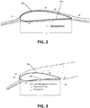
- the functionality of load management devices 28 is generally illustrated in FIGS. 2-3 . For example, FIG.
- Rotor blade 10 is subjected to airflow under normal wind conditions.
- Rotor blade 10 has a leading edge 20, a trailing edge 22, a high pressure side 24, and a low pressure side 26.
- a chord line c can be defined as a line between the leading edge 20 and trailing edge 22 of the blade 10. It is recognized that the leading side of the rotor blade 10 corresponds to the leading half of the rotor blade 10 and the trailing side of the rotor blade 10 to the trailing half of the rotor blade 10.
- a lift force created by a difference in pressure between low pressure side 26 and high pressure side 24 will increase as wind speed increases.
- the more curved surface 26a and the opposing less curved surface 24a create the dynamics of the low pressure side 26 and the high pressure side 24 due to well-known principles of aerodynamics. This, in combination with the airflow over the rotor blade 10, creates an effect known as "lift” that assists in the rotation of the rotor. Absent load management devices 28, in high wind speeds, a wind turbine 2 could experience damaging loads to one or more components.
- load management devices 28 utilizes one or more load management devices 28 to disrupt airflow along rotor blade 10 when, e.g., wind speed becomes too high, thus decreasing lift and rotor speed, and reducing the load on wind turbine 2 and its various components.
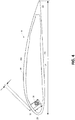
- FIG. 3 illustrates rotor blade 10 utilizing load management device 28.
- Load management device 28 may be any load management device suitable for disrupting airflow.
- load management device 28 may be, e.g., an air deflector as will be discussed more fully.
- Load management device 28 is actuated when a sensor determines the rotor blade 10 is exceeding a maximum rated speed of the wind turbine 2 and/or when a sensor senses loads on various components of wind turbine 2 are exceeding threshold values.
- Load management device 28 induces flow separation along a side of the rotor blade 10 (in the depicted embodiment, along low pressure side 26). Accordingly, when actuated, load management device 28 may help decrease loads experienced by various components of wind turbine 2 in, e.g., high wind conditions.
- FIG. 4 illustrates a cross section of rotor blade 10 employing an air deflector 32 as an example of a load management device 28 according to one or more aspects of the invention.
- rotor blade 10 further includes at least one actuator 30.
- Air deflector 32 is movable between an extended position in which the air deflector 32 extends from an exterior surface of the rotor blade 10 and a retracted position in which the air deflector 32 is substantially flush with, recessed from, or otherwise does not materially extend from the exterior surface of the rotor blade 10.
- actuator 30 may extend and retract air deflector 32 according to sensed operating conditions when directed by, e.g., a controller (not shown).
- FIG. 4 depicts a placement of actuator 30 and air deflector 32 to affect the airflow on the low pressure side 26 of rotor blade 10.
- actuator 30 and air deflector 32 may be placed to affect the airflow on the high pressure side 24 of rotor blade 10.
- actuator 30 and air deflector 32 may be placed in any position chordwise along rotor blade, such that in some embodiments air deflector 32 will be disposed in the trailing half of rotor blade 10 rather than the leading half as depicted.
- rotor blade 10 may comprise more than one actuator 30 and/or air deflector 32.
- Air deflector 32 may be sized based on the desired wind turbine condition parameter and further in view of the number of load management devices 28 used. Air deflector 32 may be made from any suitable material, such as fiberglass, carbon fiber, stainless steel, plastic, polycarbonate, and/or aluminum, etc. Air deflector 32 may be of any desired width, for example from a few inches to several feet. Additionally, air deflector 32 may extend from the airfoil surface to any desired height, e.g., from less than a percent to a few percent of the chord c, and air deflector 32 may have any suitable thickness based on the material chosen, typically less than one inch.
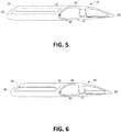
- FIGS. 5-6 are isometric sectional views through the rotor blade 10 depicting the actuator 30 with the air deflector 32 in a retracted position ( FIG. 5 ) and in an extended position ( FIG. 6 ).
- the actuator 30 is suitably mounted by an interface to substantially maintain the surface contour the rotor blade 10.
- the leading face of the actuator 30 may be mounted to the underside of the rotor blade 10. Suitable fastening arrangements such as hardware and adhesives may be used.
- multiple load management devices 28 may be provided on a rotor blade 10.
- multiple actuators 30 and/or air deflectors 32 may be arranged and spaced spanwise along the length of rotor blade 10.
- multiple air deflectors 32a-32i may be arranged along rotor blade 10.
- the remaining components of wind turbine 2 e.g., other rotor blades 10, tower 6, foundation 4, etc.
- the two additional rotor blades 10 may comprise multiple air deflectors 32 arranged in a similar fashion as those depicted in FIG.
- the number of load management devices 28 actuated (e.g., extended) at any given time may depend on sensed operating conditions of the rotor blade 10 and/or wind turbine 2.
- a sensor e.g., accelerometer, differential-pressure sensor, speed sensor, power sensor, etc.
- a controller or other suitable device may instruct one or more actuators 30 to actuate one or more air deflectors 32 in order to bring the rotor speed and/or loads within an acceptable range.
- all available load management devices 28 may be actuated in order to bring the rotor speed and/or loads into acceptable ranges. For example, if the wind turbine 2 is experiencing very high winds, all available load management devices 28 (e.g., air deflectors 32a-32i) may be actuated in order to avoid, e.g., shutdown of the wind turbine.
- a controller or other device may determine than less than all of the load management devices 28 (e.g., air deflectors 32a-32i) provided on a rotor blade 10 are needed to be actuated in order to bring the rotor speed and/or sensed loads within an acceptable range.
- the controller or similar device will instruct one or more actuators 30 to actuate less than all of the available air deflectors 32a-32i according to a determined activation sequence, as will be discussed more fully.
- some air deflectors 32 may be actuated more than others other the life of the system (e.g., the blade 10 and/or the wind turbine 2).
- each air deflector 32 may affect loads differently depending on, e.g., a spanwise location along blade 10 of air deflector 32.
- air deflector 32a e.g., a most-inboard of the air deflectors 32 located near root 35 of blade 10) may affect loads quite differently than air deflector 32i (e.g., a most-outboard of the air deflectors 32 located near tip 37 of blade 10).
- a controller may actuate air deflector 32a more frequently than 32i to control loads.
- air deflector 32a may become hyperactive (e.g., used more often than the other air deflectors 32 along blade 10). Overuse of one air deflector may lead to failure of the hyperactive deflector well before others, causing, e.g., shutdown of the wind turbine 2 to repair, e.g., the hyperactive deflector.
- the overall wind turbine 2 system may be preserved (e.g., suffer less shutdowns, etc.) by varying which air deflectors 32 are actuated such that, e.g., the duty cycle (e.g., a number of deployed/retracted cycles subject to) of each of air deflector 32 is comparable. This may lead to, e.g., less shutdowns of wind turbine 2. For example, if the duty cycle of each air deflector 32 is nearly equal, wind turbine 2 may only need to be shut down for maintenance (e.g., replacement of air deflectors 32, etc.) near a time when every air deflector 32 has reached its usable life.
- maintenance e.g., replacement of air deflectors 32, etc.
- each air deflector 32 may affect loads and/or power generation of wind turbine 2 differently depending on, e.g., operating conditions, etc., actuating a less effective air deflector 32 for the particular conditions may lead to an increase of duty cycles for the system as a whole.
- air deflector 32i e.g., an outboard-most air deflector 32
- air deflector 32a e.g., an inboard-most air deflector 32
- actuating air deflector 32a will be less effective than actuating air deflector 32i.
- the controller does actuate air deflector 32a, it may need to ultimately actuate more air deflectors 32 in order to achieve the desired load reduction than if it had actuated air deflector 32i.
- inboard air deflectors 32 e.g., air deflectors 32 near root 35
- one outboard air deflector 32 e.g., air deflectors 32 near tip 37
- the duty cycles of air deflectors 32 for this system as a whole may increase because more air deflectors 32 are actuated (in the example, two) than may be needed (e.g., one).
- a controller may use different actuation sequences to actuate one or more air deflectors 32a-32i (but, e.g., less than all air deflectors 32a-32i) along blade 10 in order to, e.g., reduce the duty cycles for each air deflector 32 and/or the system as a whole while still achieving the desired load-reduction and/or increased power benefits.
- the controller may first determine operating conditions (e.g., wind speed, rotor speed of wind turbine 2, pitch of blades 10, etc.) and determine which actuation sequence to use accordingly.
- one or more air deflectors 32 may be actuated using a root-to-tip sequence. As illustrated in FIG. 7 , a plurality of air deflectors 32a-32i may be arranged along blade 10 from a root 35 of the blade 10 to a tip 37 of the blade 10. For some operating conditions, a controller may determine that inboard air deflectors 32 (e.g., those located closer to root 35) may be more effective at achieving a desired result (e.g., reducing a load on wind turbine 2, achieving a maximum power output, e.g.) than outboard air deflectors 32 (e.g., those located closer to tip 37).
- a desired result e.g., reducing a load on wind turbine 2, achieving a maximum power output, e.g.
- the controller may actuate more than one air deflector 32 using a root-to-tip sequence.
- the controller may actuate a desired number of air deflectors 32 located closest to the root 35 (e.g., the inboard-most air deflectors 32).
- the controller may, e.g., follow a root-to-tip actuation sequence and thus actuate air deflector 32a.
- the controller may, e.g., follow a root-to-tip actuation sequence and thus start with an inboard-most air deflector 32a and actuate the next three inboard-most air deflectors 32b-32d.
- Such an actuation sequence may ultimately reduce the total duty cycles for the system as a whole, because less (but more effective) air deflectors 32 may be actuated to achieve the desired result.
- one or more air deflectors may be actuated using a tip-to-root sequence. That is, for some operating conditions, a controller may determine that outboard air deflectors 32 may be more effective at achieving a desired result (e.g., reducing load on wind turbine 2, achieving a maximum power output, etc.) than inboard air deflectors 32. Accordingly, for such operating conditions, the controller may actuate more than one air deflector 32 using a tip-to-root sequence. For such an actuation sequence, the controller may actuate a desired number of air deflectors 32 located closest to the tip 37 (e.g., the outboard-most air deflectors 32).
- a desired result e.g., reducing load on wind turbine 2, achieving a maximum power output, etc.
- the controller may, e.g., follow a tip-to-root actuation sequence and thus actuate air deflector 32i.
- the controller may, e.g., follow a tip-to-root actuation sequence and thus start with an outboard-most air deflector 32i and actuate the next three inboard-most air deflectors 32f-32h.
- Such an actuation sequence may ultimately reduce the total duty cycles for the system as a whole, because less (but more effective) air deflectors 32 may be actuated to achieve the desired result.
- one or more air deflectors 32 may be actuated using a maximum-distributed-load actuation sequence.
- one or more sensors e.g., pressure-differential sensors, accelerometers, speed sensors, etc.
- a plurality of sensors will be provided, one at the approximate location of each air deflector 32a-32i.
- blade 10 may comprise nine sensors, each at an approximate location of a corresponding air deflector 32a-32i.
- one or more controllers may determine which sensors are experiencing the largest aerodynamic loads, and actuate a corresponding air deflector 32 at the approximate location of the sensor experiencing the largest aerodynamic loads. For example, one or more controllers may determine that, e.g., three air deflectors 32 need to be actuated in order to, e.g., reduce the load acting on wind turbine 2. Further, the one or more controllers may determine that a sensor located at approximately the same location as air deflector 32e is experiencing the maximum aerodynamic load among a location at each of the air deflectors 32a-32i.
- the one or more controllers may accordingly actuate air deflector 32e, and then proportionally actuate surrounding air deflectors 32 to reach the total the number of required air deflectors 32 (e.g., air deflector 32f and air deflector 32d).
- the duty cycles of the overall system e.g., blade 10 and/or wind turbine 2
- a smaller number of total air deflectors 32 may ultimately be actuated because the air deflectors 32 located at the location of maximum aerodynamic loads may be the most effective at achieving the desired result (e.g., reducing loads acting on wind turbine 2).
- one or more air deflectors 32 may be actuated using a random actuation sequence. For example, if (as discussed) one or more air deflectors 32are routinely actuated, the one or more routinely actuated air deflectors 32 may experience much higher duty cycles than other less routinely actuated air deflectors over the life of the system. Thus, in some embodiments, one or more controllers may distribute duty cycles among air deflectors 32 using a random actuation sequence. In such embodiments, once the controller determines one or more air deflectors 32 needs to be actuated, it may randomly choose (using, e.g., a random number generator or other well-known method) one or more air deflectors 32 to actuate.
- the one or more controllers may choose three air deflectors 32 at random to actuate (e.g., air deflector 32c, air deflect 32e, and air deflector 32h).
- the life of the overall system e.g., blade 10 and/or wind turbine 2
- all air deflectors 32 may be on an approximately equal basis. Accordingly, no one air deflector 32 will experience, e.g., early failure due to hyperactivity.
- one or more air deflectors 32 may be actuated using a cycle-count actuation sequence.
- one or more controllers may record the cumulative duty cycles for each air deflector 32.
- the one or more controllers may reference the cumulative deployment cycles for each air deflector 32 and actuate one or more air deflectors 32 having the lowest total cumulative deployment cycles.
- the least-used air deflectors 32 are thus selected and the life of the overall system (e.g., blade 10 and/or wind turbine 2) may be extended.
- more than one of the above actuation sequences may be combined on a blade 10 and/or among multiple blades 10 of wind turbine 2 to achieve a desired result (e.g., maximum power production while eliminating excessive loads, etc.).
- a desired result e.g., maximum power production while eliminating excessive loads, etc.
- a combination of root-to-tip and tip-to-root actuation sequences may be used. This may be more readily understood with reference to a typical wind turbine 2 power curve 36 as depicted in FIG. 8 .
- a lift force on each blade 10 of wind turbine 2 will increase as the wind speed across the blade 10 increases.
- a rotor of wind turbine 2 will spin faster and produce more power.
- a maximum-rated rotor speed of the wind turbine 2 may be exceeded if one or more attributes of the wind turbine 2 is not adjusted to, e.g., control rotor speed.
- characteristics of the blades 10 and/or wind turbine 2 are adjusted so as to keep the rotor speed of wind turbine 2 constant (e.g., at or below a maximum-rated speed) as will be more fully discussed.
- power curve 36 may be more easily understood as a series of regions 38-46.
- startup region 38 wind speeds are relatively low. In this region, blades 10 may not be spinning very fast such that little power is actually produced.
- the wind turbine 2 enters variable speed region 40. In such a region, the speed of a rotor of wind turbine 2 will vary with wind speed. That is, as the wind speed increases, the lift force on each blade 10 increases causing the rotor to spin faster and thus produce more power. As the wind speeds over the blades 10 decrease, the lift force on each blade 10 corresponding decreases resulting in the rotor of wind turbine 2 to spin slower and thus produce less power.
- characteristics of wind turbine 2 and/or blades 10 may be configured to maximize power production. That is, because the wind turbine 2 is not operating at a maximum-rated speed, the characteristics of blades 10/wind turbine 2 are not adjusted to, e.g., purposely slow down wind turbine 2.
- transition/knee region 42 As wind turbine 2 enters transition/knee region 42, wind speeds are high enough that wind turbine 2 is approaching a maximum-rated speed (e.g., a speed at which components of wind turbine 2 may begin to fail if exceeded). As such, in the transition/knee region 42, one or more characteristics of blade 10 and/or wind turbine 2 may be altered such the speed of wind turbine 2 (and thus accordingly, power production) is limited. For example, as shown in FIG. 8 , the second derivative of the power curve 36 is negative in transition/knee region 42. Thus, although speed of wind turbine 2 (and accordingly power production) will continue increase with wind speed in the transition/knee region 42, it will do so at a decreasing rate.
- a maximum-rated speed e.g., a speed at which components of wind turbine 2 may begin to fail if exceeded.
- a maximum-rated speed e.g., a speed at which components of wind turbine 2 may begin to fail if exceeded.
- one or more controllers altering one or more characteristics of blade 10 and/or wind turbine 2 (e.g., changing pitch of blade 10, extending or retracting tip portion 18, actuating one or more air deflectors 32, etc.) to destroy lift on one or more blades 10.
- the wind turbine 2 may enter a constant speed region 44.
- the wind speeds passing over blades 10 may be high enough that characteristics of blade 10/wind turbine 2 are altered in order to keep the rotor speed (and thus power production) constant even if the wind speed continues to increase.
- the wind turbine 2 may be kept at or less than a maximum-rated rotor speed. This may be accomplished by, e.g., altering one or more characteristics of wind turbine 2 and/or blades 10 in order to, e.g., destroy lift acting on blades 10.
- a pitch of or more blades 10 may be altered, tip portion 18 may be deployed or retracted, and/or one or more air deflectors 32 may be actuated.
- shuttdown region 46 may be a region where, e.g., wind speeds are so great that a rotor speed of wind turbine 2 may not be appropriately controlled (e.g., maintained at or below a maximum-rated speed) and thus wind turbine 2 is shutdown to avoid, e.g., damage to wind turbine 2 and/or its components.
- altering the pitch of blades 10, extending or retracting tip portion 18, and/or actuating one or more air deflectors 32 in shutdown region 46 may be ineffective at keeping the rotor speed at or below a maximum-rated speed. Accordingly, in shutdown region 46, wind turbine 2 may be shutdown and/or locked into a non-spinning position to avoid damage to its components.
- a particular actuation sequence may be implemented by one or more controllers depending on what region of the power curve 36 wind turbine 2 is operating. For example, if a wind turbine 2 is operating in constant speed region 44, outboard air deflectors 32 (e.g., air deflector 32i and others close to tip 37) may not be effective due to, e.g., pitch control of blades 10. Accordingly, a tip-to-root actuation sequence in such region may be inappropriate, as more air deflectors 32 may ultimately need be deployed to achieve a desired result (e.g., load reduction) under a tip-to-root actuation sequence than under, e.g., a root-to-tip actuation sequence.
- a desired result e.g., load reduction
- pitch control of blades 10 may affect the effectiveness of air deflectors 32 located at the root 35 less than it affects the effectiveness of air deflectors 32 located at tip 37. Accordingly, for a wind turbine 2 operating in constant speed region 44, one or more controllers may actuate air deflectors using, e.g., a root-to-tip actuation sequence as discussed.
- these outboard air deflectors 32 located near tip 37 may be more effective in, e.g., the transition/knee region 42 due to, e.g., the pitch of the blades 10 or other characteristics of wind turbine 2 in that region. Accordingly, when the wind turbine 2 is operating in transition/knee region 42, one or more controllers may actuate air deflectors 32 using a tip-to-root actuation sequence as discussed.
- a controller may, e.g., employ a combination of root-to-tip and tip-to-root actuation sequences.
- the controller may first determine operating conditions (e.g., wind speed, rotor speed, loads acting on the blades 10 and/or components of wind turbine 2, etc.) and determine an appropriate activation sequence to employ accordingly.
- one or more controllers may not actuate any air deflectors 32 (in order to, e.g., achieve a maximum power output for the given wind speed).
- the controller may actuate air deflectors 32 according to a tip-to-root actuation sequence.
- the outboard-most air deflectors 32 may be most effective in this region, making a tip-to-root actuation sequence appropriate.
- the one or more controllers may switch to using a tip-to-root actuation sequence.
- outboard air deflectors 32 may be less effective at this region making a root-to-tip actuation sequence more appropriate.
- the duty cycle for each of the air deflectors 32 may be relatively equal over the lifetime of the system because, e.g., inboard air deflectors 32 may be used in certain operating conditions, and outboard air deflectors 32 may be used in others.
- a random actuation sequence may be combined with a root-to-tip actuation sequence and/or a tip-to-root actuation sequence.
- a random actuation sequence may be employed on less than all of the blades 10, with a different actuation sequence (e.g., root-to-tip, tip-to-root, maximum-distributed-load, etc.) employed on the remaining blades 10.
- duty cycles may be roughly equal among each air deflector 32 over the life of the system.
- random actuation of the air deflectors 32 on all blades 10 at once may be, e.g., too chaotic and/or lead to poor results (e.g., less than desired load reduction, poor power performed, increased duty cycles for the overall system, etc.).
- employing, e.g., a root-to-tip, tip-to-root, or maximum-distributed-load actuation sequence on one or more blades 10 of the system may stabilize the system and thus ultimately lead to the desired results (e.g., decreased loads, decreased duty cycles, increased power production, etc.).
- less than all of the blades 10 may employ a random actuation sequence, with the remaining blade(s) 10 employing, e.g., one of the other described actuation sequences (e.g., root-to-tip, tip-to-root, maximum-distributed-load, etc.).
- the controller may rotate which blade 10 employs each sequence (e.g., rotate which blade 10 of the plurality of blades 10 utilizes an actuation sequence other than random actuation) such that the benefits of random actuation (e.g., approximately equal duty cycles among each air deflector 32) may still be achieved across the entire system.
- a cycle-count actuation sequence may be combined with, e.g., root-to-tip, tip-to-root, and/or maximum-distributed-load actuation sequences in a similar manner.
- a cycle-count actuation sequence may be employed (in order to, e.g., approximately distribute duty cycles among each air deflector 32) while for the remaining blade(s) 10 any of the other described actuation sequences may be employed in order to, e.g., stabilize the system.
- the actuation sequence employed on each blade 10 in this embodiment may be rotated in order to, e.g., achieve the system-wide benefits of using cycle-count actuation methods as described.
- a cycle-count and/or a random actuation sequence may be alternated on a given blade 10 with one or more different actuation sequences (e.g., root-to-tip, tip-to-root, maximum-distributed-load, etc.) in order to, e.g., distribute duty cycles among each included air deflector 32.
- actuation sequences e.g., root-to-tip, tip-to-root, maximum-distributed-load, etc.
- a root-to-tip actuation sequence may be employed on a blade 10 and, once stabilized, the blade 10 may switch to, e.g.,a cycle-count actuation sequence.
- a maximum-distributed-load actuation sequence may be employed on a blade 10 and, once stabilized, the blade 10 may switch to, e.g., a random actuation sequence. Accordingly, the relative duty cycles of each air deflector 32 may remain approximately equal.
- any of the described actuation systems may be employed as a rotor-based actuation sequence.
- a total number of air deflectors 32 needed to be actuated on a rotor as a whole may be determined and then one or more of the above actuation sequences may be employed with respect to that rotor as a whole.
- one or more controllers may determine from sensed operating conditions (by, e.g., an accelerometer, pressure-differential sensor, speed sensor, etc.) that one or more air deflectors 32 need to be actuated in order to bring loads acting on wind turbine 2 and/or a rotor speed of wind turbine 2 within an acceptable level. Accordingly, the one or more controllers may determine a total number of air deflectors to be actuated for the wind turbine 2 rotor as a whole. For example, the one or more controllers may determine that seven total air deflectors 32 need to be actuated to achieve a desired result (e.g., bring rotor to an acceptable speed). Accordingly, the one or more controllers may actuate seven air deflectors 32 using any of the described actuation methods in a rotor-based manner.
- sensed operating conditions by, e.g., an accelerometer, pressure-differential sensor, speed sensor, etc.
- the one or more controllers may actuate the seven inboard-most air deflectors 32 with respect to the rotor as a whole.
- the one or more controllers may actuate, e.g., air deflectors 32a, 32b, and 32c on the depicted blade 10 in FIG. 7 , along with the two inboard-most air deflectors 32 on each of the other two blades 10 (partially show in FIG. 7 ).
- the one or more controllers may actuate the seven outboard-most air deflectors 32 with respect to the rotor as a whole.
- the one or more controllers may actuate, e.g., air deflectors 32g, 32h, and 32i on the depicted blade 10 in FIG. 7 , along with the two outboard-most air deflectors 32 on each of the other two blades 10 (partially show in FIG. 7 ).
- the one or more controllers may actuate seven random air deflectors 32 across the entire rotor system.
- one of blades 10 may have, e.g., one air deflector 32 actuated at any random location along its length
- another of blades 10 may have, e.g., two air deflectors 32 actuated at any random location along its length
- another of blades 10 may have, e.g., four air deflectors 32 actuated at any random location along its length.
- the one or more controllers may actuate the seven air deflectors 32 using a cycle-count actuation sequence.
- the one or more controllers may, e.g., determine the seven air deflectors 32 out of all air deflectors 32 included on wind turbine 2 which have been cumulatively actuated the least. For example, in FIG. 7 , if each of the two partially shown blades 10 similarly comprise nine air deflectors 32 as with the fully shown blade 10, then the one or more controllers in this embodiment may determine the seven air deflectors 32 out of the twenty-seven total air deflectors 32 which have been actuated the least and accordingly actuate each of those seven to achieve the desired result.
- each air deflector 32 actuated may have a different maximum height (e.g., a height from one of low pressure side 26 or high pressure side 24 to the edge of the actuated air deflector 32 as indicated by "h" in FIG. 4 ) than other air deflectors 32 provided on any of the blades 10.
- air deflector 31a may have a different maximum height than, e.g., air deflector 32e.
- each air deflector may have a maximum height equal to, e.g., a certain percentage of a corresponding chord length ("c" in FIG. 4 ) at the spanwise location of blade 10 where the air deflector 32 is located. Accordingly, because chord length may vary along the length of blade 10 (e.g., may be longer at a location of air deflector 32a than a location of air deflector 32e), so too may a maximum height of each air deflector 32 vary along the length of blade 10 (e.g., air deflector 32a may have a greater maximum height than, e.g., air deflector 32e).
- each air deflector 32 actuated may be configured to be actuated to a variable height.
- actuator 30 of each air deflector 32 may be such that each air deflector 32 may be actuated to a maximum height or any fraction thereof.
- the one or more controllers may actuate each air deflector to a variable height.
- this finer-grain (e.g., variable height) actuation may result in, e.g., better control performance.
- the one or more controllers may be able to achieve, e.g., more load reduction with less power loss.
- air deflectors 32 may be actuated according to a distributed actuation system.
- each blade 10 may comprise multiple air deflectors (e.g., air deflectors 32a-32i as depicted in FIG. 7 ) with each air deflector 32 comprising a corresponding sensor (e.g., pressure-differential, accelerometer, speed, etc.) and/or controller (not shown).
- the corresponding controller of a particular air deflector 32 may read a corresponding sensor measurement, and determine a fraction of actuation for that particular air deflector accordingly (e.g., 0 to 100% actuation).
- each controller may determine operating conditions (e.g., wind speed, acceleration, aerodynamic load, etc.) at the location of a corresponding air deflector 32 (according to, e.g., a reading of the sensor provided at that location) and actuate that air deflector 32 if necessary to, e.g., reduce load.
- operating conditions e.g., wind speed, acceleration, aerodynamic load, etc.
- air deflector 32 may be capable of being actuated to a variable height.
- a controller corresponding to a specific air deflector 32 may determine for some operating conditions that the air defector 32 does not need to be actuated, and thus the air deflector 32 will be actuated to 0% of its maximum height.
- the controller corresponding to a specific air deflector 32 may determine that the air deflector 32 needs to be actuated, but not fully, and thus the controller may actuate the air deflector 32 to, e.g., a fraction of its maximum height (e.g., 50%).
- the controller corresponding to specific air deflector 32 may determine that the air deflector 32 needs to be actuated to a maximum height, and thus the controller may actuate the air deflector 32 to its maximum height (e.g., 100%).
- Systems employing such a distributed actuation may, in some embodiments, have higher reliability than other systems (e.g., systems not utilizing a sensor and/or controller at each air deflector 32) because if one controller/air deflector 32 combination fails, other controller/sensor/air deflector 32 combinations may still operate.
- the methods and features recited herein may further be implemented through any number of computer readable media that are able to store computer readable instructions.
- Examples of computer readable mediums that may be used include RAM, ROM, EEPROM, flash memory, or other memory technology, CD-ROM, DVD or other optical disk storage, magnetic cassettes, magnetic tape, magnetic storage and the like.
Landscapes
- Engineering & Computer Science (AREA)
- Physics & Mathematics (AREA)
- Fluid Mechanics (AREA)
- Life Sciences & Earth Sciences (AREA)
- Sustainable Development (AREA)
- Sustainable Energy (AREA)
- Chemical & Material Sciences (AREA)
- Combustion & Propulsion (AREA)
- Mechanical Engineering (AREA)
- General Engineering & Computer Science (AREA)
- Wind Motors (AREA)
Claims (8)
- Verfahren zum Betätigen von Lastmanagementvorrichtungen auf einer aerodynamischen Fläche (10), wobei das Verfahren umfasst:Bestimmen, mittels einer Steuereinrichtung der aerodynamischen Fläche, von Betriebsbedingungen an einer aerodynamischen Fläche (10);Bestimmen, mittels der Steuereinrichtung der aerodynamischen Fläche, einer Anzahl von Lastmanagementvorrichtungen (28), welche gemäß den Betriebsbedingungen betätigt werden sollen, wobei die Anzahl der zu betätigenden Lastmanagementvorrichtungen kleiner ist als alle von der Vielzahl von Lastmanagementvorrichtungen; undBetätigen, mittels der Steuereinrichtung der aerodynamischen Fläche, der Anzahl von Lastmanagementvorrichtungen (28) gemäß einer Betätigungsabfolge zum Betätigen der Anzahl von Lastmanagementvorrichtungen (28);gekennzeichnet durch Bestimmen, mittels der Steuereinrichtung der aerodynamischen Fläche, einer Zykluszählung, welche angibt, wie viele Male jede von der Vielzahl von Lastmanagementvorrichtungen (28) zuvor betätigt worden ist, wobei die Betätigungsabfolge eine Zykluszählungsbetätigungsabfolge ist, sodass Betätigen der Anzahl von Lastmanagementvorrichtungen Betätigen einer Lastmanagementvorrichtung (28) mit einer minimalen Zykluszählung von den bestimmten Zykluszählungen umfasst.
- Verfahren nach Anspruch 1, wobei die Vielzahl von Lastmanagementvorrichtungen (28) konfiguriert sind, um für variable Höhen betätigt zu werden, und wobei Betätigen der Anzahl von Lastmanagementvorrichtungen (28) Betätigen einer ersten Lastmanagementvorrichtung für eine unterschiedliche Höhe als eine zweite Lastmanagementvorrichtung umfasst.
- Verfahren nach Anspruch 1, wobei Bestimmen der Betriebsbedingungen an der aerodynamischen Fläche (10) Bestimmen einer aerodynamischen Last an der aerodynamischen Fläche (10) an einem Ort von jeder von der Vielzahl von Lastmanagementvorrichtungen (28) umfasst.
- Verfahren zum Betätigen von Lastmanagementvorrichtungen (28) auf Flügeln (10) einer Windturbine (2), wobei die Lastmanagementvorrichtungen vorzugsweise Ablenker (32) sind, wobei das Verfahren umfasst:Bestimmen, mittels einer Flügelsteuervorrichtung, von Betriebsbedingungen der Windturbine; undfür jeden Flügel von einer Vielzahl von Flügeln der Windturbine: Bestimmen, mittels der Flügelsteuervorrichtung, einer Anzahl von Lastmanagementvorrichtungen, welche auf dem Flügel gemäß den Betriebsbedingungen betätigt werden sollen, wobei die Anzahl der zu betätigenden Lastmanagementvorrichtungen kleiner ist als alle von der Vielzahl von Lastmanagementvorrichtungen auf dem Flügel; Bestimmen, mittels der Flügelsteuervorrichtung, einer Betätigungsabfolge zum Betätigen der Anzahl von Lastmanagementvorrichtungen auf dem Flügel; und Betätigen, mittels der Flügelsteuervorrichtung, der Anzahl von Lastmanagementvorrichtungen gemäß der bestimmten Betätigungsabfolge;dadurch gekennzeichnet dass, für einen ersten Flügel von der Vielzahl von Flügeln der Windturbine, die Bestimmung einer Betätigungsabfolge Bestimmen, mittels der Flügelsteuervorrichtung, einer Zykluszählung umfasst, welche angibt, wie viele Male jede von der Vielzahl von Lastmanagementvorrichtungen zuvor betätigt worden ist, wobei die Betätigungsabfolge für den ersten Flügel eine Zykluszählungsbetätigungsabfolge ist, sodass Betätigen der Anzahl von Lastmanagementvorrichtungen Betätigen einer Lastmanagementvorrichtung mit einer minimalen Zykluszählung von den bestimmten Zykluszählungen umfasst.
- Verfahren nach Anspruch 4, wobei die Betätigungsabfolge für den ersten Flügel von der Vielzahl von Flügeln sich von der Betätigungsabfolge für einen zweiten Flügel von der Vielzahl von Flügeln unterscheidet.
- Verfahren nach Anspruch 5, wobei die Betätigungsabfolge für den ersten Flügel (10) die Zykluszählungsbetätigungsabfolge ist, welche für weniger als alle von den Flügeln angewendet wird, und die Betätigungsabfolge für den zweiten Flügel (10) eine Wurzel-zu-Spitze-Abfolge ist, sodass Betätigen der Anzahl von Lastmanagementvorrichtungen für den zweiten Flügel (10) Betätigen der Anzahl von am weitesten innenliegenden Lastmanagementvorrichtungen (32a-32d) umfasst.
- Verfahren nach Anspruch 5, wobei die Betätigungsabfolge für den ersten Flügel (10) die Zykluszählungsbetätigungsabfolge ist, welche für weniger als alle von den Flügeln angewendet wird, und die Betätigungsabfolge für den zweiten Flügel (10) eine Spitze-zu-Wurzel-Abfolge ist, sodass Betätigen der Anzahl von Lastmanagementvorrichtungen für den zweiten Flügel (10) Betätigen der Anzahl von am weitesten innenliegenden Lastmanagementvorrichtungen (32a-32d) umfasst.
- Verfahren nach Anspruch 4, wobei die Vielzahl von Lastmanagementvorrichtungen (28) konfiguriert sind, um für variable Höhen betätigt zu werden, und wobei Betätigen der Anzahl von Lastmanagementvorrichtungen Betätigen einer ersten Lastmanagementvorrichtung für eine unterschiedliche Höhe als eine zweite Lastmanagementvorrichtung umfasst.
Priority Applications (1)
| Application Number | Priority Date | Filing Date | Title |
|---|---|---|---|
| PL14159295T PL2778400T3 (pl) | 2013-03-15 | 2014-03-12 | Uruchamianie urządzeń zarządzających obciążeniem na łopatach aerodynamicznych |
Applications Claiming Priority (1)
| Application Number | Priority Date | Filing Date | Title |
|---|---|---|---|
| US13/837,220 US9506453B2 (en) | 2013-03-15 | 2013-03-15 | Actuation of distributed load management devices on aerodynamic blades |
Publications (3)
| Publication Number | Publication Date |
|---|---|
| EP2778400A2 EP2778400A2 (de) | 2014-09-17 |
| EP2778400A3 EP2778400A3 (de) | 2014-12-24 |
| EP2778400B1 true EP2778400B1 (de) | 2019-05-22 |
Family
ID=50272431
Family Applications (1)
| Application Number | Title | Priority Date | Filing Date |
|---|---|---|---|
| EP14159295.6A Active EP2778400B1 (de) | 2013-03-15 | 2014-03-12 | Steuerung von Lastmanagementvorrichtungen auf aerodynamischen Flügeln |
Country Status (11)
| Country | Link |
|---|---|
| US (1) | US9506453B2 (de) |
| EP (1) | EP2778400B1 (de) |
| JP (1) | JP2014181710A (de) |
| KR (1) | KR20140113510A (de) |
| AU (1) | AU2014201456A1 (de) |
| BR (1) | BR102014006348B1 (de) |
| CA (1) | CA2845313C (de) |
| DK (1) | DK2778400T3 (de) |
| ES (1) | ES2743739T3 (de) |
| IN (1) | IN2014DE00773A (de) |
| PL (1) | PL2778400T3 (de) |
Families Citing this family (7)
| Publication number | Priority date | Publication date | Assignee | Title |
|---|---|---|---|---|
| US9388791B2 (en) * | 2013-03-15 | 2016-07-12 | Frontier Wind, Llc | Mounting arrangement for load compensating device |
| US10385826B2 (en) * | 2014-09-12 | 2019-08-20 | Ge Infrastructure Technology, Llc | Wind turbine air deflector system control |
| EP3020959B1 (de) * | 2014-11-11 | 2019-01-02 | GE Renewable Technologies Wind B.V. | Verfahren zum Betreiben einer Windturbine und Windturbinen |
| EP3516210B1 (de) * | 2016-09-22 | 2021-06-02 | Vestas Wind Systems A/S | Verfahren zur steuerung von luftleitblechen und neigungswinkeln von windturbinenschaufeln |
| EP3667073A1 (de) * | 2018-12-13 | 2020-06-17 | Siemens Gamesa Renewable Energy A/S | Steuerung von segmentierten zusatzelementen einer windturbinenschaufel |
| US11278021B1 (en) | 2021-02-24 | 2022-03-22 | Timothy Just | Wildlife deterring windmill |
| US11672243B2 (en) | 2021-02-24 | 2023-06-13 | Timothy Just | Wildlife deterring windmill |
Family Cites Families (10)
| Publication number | Priority date | Publication date | Assignee | Title |
|---|---|---|---|---|
| US2622686A (en) | 1942-07-21 | 1952-12-23 | Chevreau Rene Louis Pier Marie | Wind motor |
| WO2002038442A2 (en) | 2000-10-10 | 2002-05-16 | The Regents Of The University Of California | Microfabricated translational stages for control of aerodynamic loading |
| US6902370B2 (en) | 2002-06-04 | 2005-06-07 | Energy Unlimited, Inc. | Telescoping wind turbine blade |
| JP2003056924A (ja) | 2002-08-05 | 2003-02-26 | Yanmar Co Ltd | エンジンヒートポンプ |
| JP3996945B1 (ja) * | 2007-02-20 | 2007-10-24 | 常夫 野口 | 垂直軸型風車 |
| WO2009097049A2 (en) * | 2007-12-14 | 2009-08-06 | Alliance For Sustainable Energy, Llc | Dual-axis resonance testing of wind turbine blades |
| US8192161B2 (en) | 2008-05-16 | 2012-06-05 | Frontier Wind, Llc. | Wind turbine with deployable air deflectors |
| US8267654B2 (en) * | 2008-05-16 | 2012-09-18 | Frontier Wind, Llc | Wind turbine with gust compensating air deflector |
| US9327839B2 (en) * | 2011-08-05 | 2016-05-03 | General Atomics | Method and apparatus for inhibiting formation of and/or removing ice from aircraft components |
| US8444384B2 (en) * | 2011-08-25 | 2013-05-21 | General Electric Company | Rotor blade assembly and method for adjusting loading capability of rotor blade |
-
2013
- 2013-03-15 US US13/837,220 patent/US9506453B2/en active Active
-
2014
- 2014-03-11 CA CA2845313A patent/CA2845313C/en active Active
- 2014-03-12 PL PL14159295T patent/PL2778400T3/pl unknown
- 2014-03-12 DK DK14159295.6T patent/DK2778400T3/da active
- 2014-03-12 ES ES14159295T patent/ES2743739T3/es active Active
- 2014-03-12 EP EP14159295.6A patent/EP2778400B1/de active Active
- 2014-03-13 AU AU2014201456A patent/AU2014201456A1/en not_active Abandoned
- 2014-03-14 KR KR1020140030181A patent/KR20140113510A/ko not_active Application Discontinuation
- 2014-03-14 IN IN773DE2014 patent/IN2014DE00773A/en unknown
- 2014-03-17 BR BR102014006348-0A patent/BR102014006348B1/pt active IP Right Grant
- 2014-03-17 JP JP2014052923A patent/JP2014181710A/ja not_active Ceased
Non-Patent Citations (1)
| Title |
|---|
| None * |
Also Published As
| Publication number | Publication date |
|---|---|
| US20140271184A1 (en) | 2014-09-18 |
| IN2014DE00773A (de) | 2015-06-12 |
| KR20140113510A (ko) | 2014-09-24 |
| JP2014181710A (ja) | 2014-09-29 |
| PL2778400T3 (pl) | 2021-07-19 |
| BR102014006348B1 (pt) | 2022-02-08 |
| AU2014201456A1 (en) | 2014-10-02 |
| ES2743739T3 (es) | 2020-02-20 |
| CA2845313C (en) | 2017-12-05 |
| BR102014006348A2 (pt) | 2014-12-23 |
| US9506453B2 (en) | 2016-11-29 |
| CA2845313A1 (en) | 2014-09-15 |
| DK2778400T3 (da) | 2019-08-26 |
| EP2778400A3 (de) | 2014-12-24 |
| EP2778400A2 (de) | 2014-09-17 |
Similar Documents
| Publication | Publication Date | Title |
|---|---|---|
| EP2778400B1 (de) | Steuerung von Lastmanagementvorrichtungen auf aerodynamischen Flügeln | |
| US10844837B2 (en) | Wind turbine with deployable air deflectors | |
| US9458825B2 (en) | Actuation mechanisms for load management devices on aerodynamic blades | |
| US8267654B2 (en) | Wind turbine with gust compensating air deflector | |
| US9689374B2 (en) | Method and apparatus for reduction of fatigue and gust loads on wind turbine blades | |
| US20100226774A1 (en) | Wind turbine control system and apparatus | |
| EP2267298A2 (de) | Windturbineblatt mit drehbaren Finnen an der Spitze | |
| US20110255974A1 (en) | Configurable winglet for wind turbine blades | |
| EP2466121A2 (de) | Windturbine, aerodynamische Anordnung für die Verwendung in einer Windturbine und Verfahren zur Anordnung davon | |
| EP2405129B1 (de) | Windturbinenschaufel mit variabler Austrittskante | |
| EP3080402B1 (de) | Schaufelströmungsdeflektor | |
| JP2010121518A (ja) | 縦軸式マグナス型風力発電装置 | |
| EP2778398A2 (de) | Ausfallsicheres Einsatzsystem für eine Luftströmungsablenkungsplatte einer Windturbinenschaufel | |
| EP2577050B1 (de) | Verfahren zur reduktion von strömungsinduzierten kräften durch karmansche wirbel auf einem windturbinenrotorblatt | |
| US10161252B2 (en) | Blade flow deflector | |
| WO2015176868A1 (en) | Aerodynamic device of a rotor blade of a wind turbine | |
| JP4533991B1 (ja) | 小型プロペラ風車 | |
| CN117536772A (zh) | 一种垂直轴风力发电机及其叶片 |
Legal Events
| Date | Code | Title | Description |
|---|---|---|---|
| 17P | Request for examination filed |
Effective date: 20140312 |
|
| AK | Designated contracting states |
Kind code of ref document: A2 Designated state(s): AL AT BE BG CH CY CZ DE DK EE ES FI FR GB GR HR HU IE IS IT LI LT LU LV MC MK MT NL NO PL PT RO RS SE SI SK SM TR |
|
| AX | Request for extension of the european patent |
Extension state: BA ME |
|
| PUAI | Public reference made under article 153(3) epc to a published international application that has entered the european phase |
Free format text: ORIGINAL CODE: 0009012 |
|
| PUAL | Search report despatched |
Free format text: ORIGINAL CODE: 0009013 |
|
| AK | Designated contracting states |
Kind code of ref document: A3 Designated state(s): AL AT BE BG CH CY CZ DE DK EE ES FI FR GB GR HR HU IE IS IT LI LT LU LV MC MK MT NL NO PL PT RO RS SE SI SK SM TR |
|
| AX | Request for extension of the european patent |
Extension state: BA ME |
|
| RIC1 | Information provided on ipc code assigned before grant |
Ipc: F03D 7/02 20060101AFI20141120BHEP |
|
| RAP1 | Party data changed (applicant data changed or rights of an application transferred) |
Owner name: GE INFRASTRUCTURE TECHNOLOGY, LLC |
|
| STAA | Information on the status of an ep patent application or granted ep patent |
Free format text: STATUS: EXAMINATION IS IN PROGRESS |
|
| 17Q | First examination report despatched |
Effective date: 20170915 |
|
| GRAP | Despatch of communication of intention to grant a patent |
Free format text: ORIGINAL CODE: EPIDOSNIGR1 |
|
| STAA | Information on the status of an ep patent application or granted ep patent |
Free format text: STATUS: GRANT OF PATENT IS INTENDED |
|
| INTG | Intention to grant announced |
Effective date: 20180926 |
|
| GRAS | Grant fee paid |
Free format text: ORIGINAL CODE: EPIDOSNIGR3 |
|
| GRAA | (expected) grant |
Free format text: ORIGINAL CODE: 0009210 |
|
| STAA | Information on the status of an ep patent application or granted ep patent |
Free format text: STATUS: THE PATENT HAS BEEN GRANTED |
|
| AK | Designated contracting states |
Kind code of ref document: B1 Designated state(s): AL AT BE BG CH CY CZ DE DK EE ES FI FR GB GR HR HU IE IS IT LI LT LU LV MC MK MT NL NO PL PT RO RS SE SI SK SM TR |
|
| REG | Reference to a national code |
Ref country code: GB Ref legal event code: FG4D |
|
| REG | Reference to a national code |
Ref country code: CH Ref legal event code: EP |
|
| REG | Reference to a national code |
Ref country code: IE Ref legal event code: FG4D |
|
| REG | Reference to a national code |
Ref country code: DE Ref legal event code: R096 Ref document number: 602014047086 Country of ref document: DE |
|
| REG | Reference to a national code |
Ref country code: AT Ref legal event code: REF Ref document number: 1136430 Country of ref document: AT Kind code of ref document: T Effective date: 20190615 |
|
| REG | Reference to a national code |
Ref country code: DK Ref legal event code: T3 Effective date: 20190822 |
|
| REG | Reference to a national code |
Ref country code: NL Ref legal event code: MP Effective date: 20190522 |
|
| REG | Reference to a national code |
Ref country code: LT Ref legal event code: MG4D |
|
| PG25 | Lapsed in a contracting state [announced via postgrant information from national office to epo] |
Ref country code: NL Free format text: LAPSE BECAUSE OF FAILURE TO SUBMIT A TRANSLATION OF THE DESCRIPTION OR TO PAY THE FEE WITHIN THE PRESCRIBED TIME-LIMIT Effective date: 20190522 Ref country code: SE Free format text: LAPSE BECAUSE OF FAILURE TO SUBMIT A TRANSLATION OF THE DESCRIPTION OR TO PAY THE FEE WITHIN THE PRESCRIBED TIME-LIMIT Effective date: 20190522 Ref country code: HR Free format text: LAPSE BECAUSE OF FAILURE TO SUBMIT A TRANSLATION OF THE DESCRIPTION OR TO PAY THE FEE WITHIN THE PRESCRIBED TIME-LIMIT Effective date: 20190522 Ref country code: AL Free format text: LAPSE BECAUSE OF FAILURE TO SUBMIT A TRANSLATION OF THE DESCRIPTION OR TO PAY THE FEE WITHIN THE PRESCRIBED TIME-LIMIT Effective date: 20190522 Ref country code: NO Free format text: LAPSE BECAUSE OF FAILURE TO SUBMIT A TRANSLATION OF THE DESCRIPTION OR TO PAY THE FEE WITHIN THE PRESCRIBED TIME-LIMIT Effective date: 20190822 Ref country code: PT Free format text: LAPSE BECAUSE OF FAILURE TO SUBMIT A TRANSLATION OF THE DESCRIPTION OR TO PAY THE FEE WITHIN THE PRESCRIBED TIME-LIMIT Effective date: 20190922 Ref country code: FI Free format text: LAPSE BECAUSE OF FAILURE TO SUBMIT A TRANSLATION OF THE DESCRIPTION OR TO PAY THE FEE WITHIN THE PRESCRIBED TIME-LIMIT Effective date: 20190522 Ref country code: LT Free format text: LAPSE BECAUSE OF FAILURE TO SUBMIT A TRANSLATION OF THE DESCRIPTION OR TO PAY THE FEE WITHIN THE PRESCRIBED TIME-LIMIT Effective date: 20190522 |
|
| PG25 | Lapsed in a contracting state [announced via postgrant information from national office to epo] |
Ref country code: BG Free format text: LAPSE BECAUSE OF FAILURE TO SUBMIT A TRANSLATION OF THE DESCRIPTION OR TO PAY THE FEE WITHIN THE PRESCRIBED TIME-LIMIT Effective date: 20190822 Ref country code: RS Free format text: LAPSE BECAUSE OF FAILURE TO SUBMIT A TRANSLATION OF THE DESCRIPTION OR TO PAY THE FEE WITHIN THE PRESCRIBED TIME-LIMIT Effective date: 20190522 Ref country code: LV Free format text: LAPSE BECAUSE OF FAILURE TO SUBMIT A TRANSLATION OF THE DESCRIPTION OR TO PAY THE FEE WITHIN THE PRESCRIBED TIME-LIMIT Effective date: 20190522 Ref country code: GR Free format text: LAPSE BECAUSE OF FAILURE TO SUBMIT A TRANSLATION OF THE DESCRIPTION OR TO PAY THE FEE WITHIN THE PRESCRIBED TIME-LIMIT Effective date: 20190823 |
|
| REG | Reference to a national code |
Ref country code: AT Ref legal event code: MK05 Ref document number: 1136430 Country of ref document: AT Kind code of ref document: T Effective date: 20190522 |
|
| PG25 | Lapsed in a contracting state [announced via postgrant information from national office to epo] |
Ref country code: AT Free format text: LAPSE BECAUSE OF FAILURE TO SUBMIT A TRANSLATION OF THE DESCRIPTION OR TO PAY THE FEE WITHIN THE PRESCRIBED TIME-LIMIT Effective date: 20190522 Ref country code: EE Free format text: LAPSE BECAUSE OF FAILURE TO SUBMIT A TRANSLATION OF THE DESCRIPTION OR TO PAY THE FEE WITHIN THE PRESCRIBED TIME-LIMIT Effective date: 20190522 Ref country code: CZ Free format text: LAPSE BECAUSE OF FAILURE TO SUBMIT A TRANSLATION OF THE DESCRIPTION OR TO PAY THE FEE WITHIN THE PRESCRIBED TIME-LIMIT Effective date: 20190522 Ref country code: RO Free format text: LAPSE BECAUSE OF FAILURE TO SUBMIT A TRANSLATION OF THE DESCRIPTION OR TO PAY THE FEE WITHIN THE PRESCRIBED TIME-LIMIT Effective date: 20190522 Ref country code: SK Free format text: LAPSE BECAUSE OF FAILURE TO SUBMIT A TRANSLATION OF THE DESCRIPTION OR TO PAY THE FEE WITHIN THE PRESCRIBED TIME-LIMIT Effective date: 20190522 |
|
| REG | Reference to a national code |
Ref country code: DE Ref legal event code: R097 Ref document number: 602014047086 Country of ref document: DE |
|
| PG25 | Lapsed in a contracting state [announced via postgrant information from national office to epo] |
Ref country code: SM Free format text: LAPSE BECAUSE OF FAILURE TO SUBMIT A TRANSLATION OF THE DESCRIPTION OR TO PAY THE FEE WITHIN THE PRESCRIBED TIME-LIMIT Effective date: 20190522 Ref country code: IT Free format text: LAPSE BECAUSE OF FAILURE TO SUBMIT A TRANSLATION OF THE DESCRIPTION OR TO PAY THE FEE WITHIN THE PRESCRIBED TIME-LIMIT Effective date: 20190522 |
|
| PLBE | No opposition filed within time limit |
Free format text: ORIGINAL CODE: 0009261 |
|
| STAA | Information on the status of an ep patent application or granted ep patent |
Free format text: STATUS: NO OPPOSITION FILED WITHIN TIME LIMIT |
|
| 26N | No opposition filed |
Effective date: 20200225 |
|
| PG25 | Lapsed in a contracting state [announced via postgrant information from national office to epo] |
Ref country code: SI Free format text: LAPSE BECAUSE OF FAILURE TO SUBMIT A TRANSLATION OF THE DESCRIPTION OR TO PAY THE FEE WITHIN THE PRESCRIBED TIME-LIMIT Effective date: 20190522 |
|
| PG25 | Lapsed in a contracting state [announced via postgrant information from national office to epo] |
Ref country code: MC Free format text: LAPSE BECAUSE OF FAILURE TO SUBMIT A TRANSLATION OF THE DESCRIPTION OR TO PAY THE FEE WITHIN THE PRESCRIBED TIME-LIMIT Effective date: 20190522 |
|
| REG | Reference to a national code |
Ref country code: CH Ref legal event code: PL |
|
| REG | Reference to a national code |
Ref country code: BE Ref legal event code: MM Effective date: 20200331 |
|
| PG25 | Lapsed in a contracting state [announced via postgrant information from national office to epo] |
Ref country code: LU Free format text: LAPSE BECAUSE OF NON-PAYMENT OF DUE FEES Effective date: 20200312 |
|
| PG25 | Lapsed in a contracting state [announced via postgrant information from national office to epo] |
Ref country code: CH Free format text: LAPSE BECAUSE OF NON-PAYMENT OF DUE FEES Effective date: 20200331 Ref country code: LI Free format text: LAPSE BECAUSE OF NON-PAYMENT OF DUE FEES Effective date: 20200331 |
|
| PG25 | Lapsed in a contracting state [announced via postgrant information from national office to epo] |
Ref country code: BE Free format text: LAPSE BECAUSE OF NON-PAYMENT OF DUE FEES Effective date: 20200331 |
|
| PG25 | Lapsed in a contracting state [announced via postgrant information from national office to epo] |
Ref country code: MT Free format text: LAPSE BECAUSE OF FAILURE TO SUBMIT A TRANSLATION OF THE DESCRIPTION OR TO PAY THE FEE WITHIN THE PRESCRIBED TIME-LIMIT Effective date: 20190522 Ref country code: CY Free format text: LAPSE BECAUSE OF FAILURE TO SUBMIT A TRANSLATION OF THE DESCRIPTION OR TO PAY THE FEE WITHIN THE PRESCRIBED TIME-LIMIT Effective date: 20190522 |
|
| PG25 | Lapsed in a contracting state [announced via postgrant information from national office to epo] |
Ref country code: MK Free format text: LAPSE BECAUSE OF FAILURE TO SUBMIT A TRANSLATION OF THE DESCRIPTION OR TO PAY THE FEE WITHIN THE PRESCRIBED TIME-LIMIT Effective date: 20190522 Ref country code: IS Free format text: LAPSE BECAUSE OF FAILURE TO SUBMIT A TRANSLATION OF THE DESCRIPTION OR TO PAY THE FEE WITHIN THE PRESCRIBED TIME-LIMIT Effective date: 20190922 |
|
| P01 | Opt-out of the competence of the unified patent court (upc) registered |
Effective date: 20230530 |
|
| PGFP | Annual fee paid to national office [announced via postgrant information from national office to epo] |
Ref country code: IE Payment date: 20240222 Year of fee payment: 11 |
|
| PGFP | Annual fee paid to national office [announced via postgrant information from national office to epo] |
Ref country code: DE Payment date: 20240220 Year of fee payment: 11 Ref country code: GB Payment date: 20240220 Year of fee payment: 11 |
|
| PGFP | Annual fee paid to national office [announced via postgrant information from national office to epo] |
Ref country code: TR Payment date: 20240301 Year of fee payment: 11 Ref country code: PL Payment date: 20240226 Year of fee payment: 11 Ref country code: FR Payment date: 20240221 Year of fee payment: 11 Ref country code: DK Payment date: 20240220 Year of fee payment: 11 |
|
| PGFP | Annual fee paid to national office [announced via postgrant information from national office to epo] |
Ref country code: ES Payment date: 20240402 Year of fee payment: 11 |