EP2778367B1 - Verbrennungsmotor mit Vor- und Haupteinspritzung - Google Patents
Verbrennungsmotor mit Vor- und Haupteinspritzung Download PDFInfo
- Publication number
- EP2778367B1 EP2778367B1 EP14158964.8A EP14158964A EP2778367B1 EP 2778367 B1 EP2778367 B1 EP 2778367B1 EP 14158964 A EP14158964 A EP 14158964A EP 2778367 B1 EP2778367 B1 EP 2778367B1
- Authority
- EP
- European Patent Office
- Prior art keywords
- fuel
- conduit
- pilot
- engine
- pressure
- Prior art date
- Legal status (The legal status is an assumption and is not a legal conclusion. Google has not performed a legal analysis and makes no representation as to the accuracy of the status listed.)
- Active
Links
Images


Classifications
-
- F—MECHANICAL ENGINEERING; LIGHTING; HEATING; WEAPONS; BLASTING
- F02—COMBUSTION ENGINES; HOT-GAS OR COMBUSTION-PRODUCT ENGINE PLANTS
- F02B—INTERNAL-COMBUSTION PISTON ENGINES; COMBUSTION ENGINES IN GENERAL
- F02B19/00—Engines characterised by precombustion chambers
- F02B19/10—Engines characterised by precombustion chambers with fuel introduced partly into pre-combustion chamber, and partly into cylinder
- F02B19/1019—Engines characterised by precombustion chambers with fuel introduced partly into pre-combustion chamber, and partly into cylinder with only one pre-combustion chamber
- F02B19/108—Engines characterised by precombustion chambers with fuel introduced partly into pre-combustion chamber, and partly into cylinder with only one pre-combustion chamber with fuel injection at least into pre-combustion chamber, i.e. injector mounted directly in the pre-combustion chamber
-
- F—MECHANICAL ENGINEERING; LIGHTING; HEATING; WEAPONS; BLASTING
- F01—MACHINES OR ENGINES IN GENERAL; ENGINE PLANTS IN GENERAL; STEAM ENGINES
- F01C—ROTARY-PISTON OR OSCILLATING-PISTON MACHINES OR ENGINES
- F01C1/00—Rotary-piston machines or engines
- F01C1/22—Rotary-piston machines or engines of internal-axis type with equidirectional movement of co-operating members at the points of engagement, or with one of the co-operating members being stationary, the inner member having more teeth or tooth- equivalents than the outer member
-
- F—MECHANICAL ENGINEERING; LIGHTING; HEATING; WEAPONS; BLASTING
- F02—COMBUSTION ENGINES; HOT-GAS OR COMBUSTION-PRODUCT ENGINE PLANTS
- F02B—INTERNAL-COMBUSTION PISTON ENGINES; COMBUSTION ENGINES IN GENERAL
- F02B53/00—Internal-combustion aspects of rotary-piston or oscillating-piston engines
- F02B53/10—Fuel supply; Introducing fuel to combustion space
-
- F—MECHANICAL ENGINEERING; LIGHTING; HEATING; WEAPONS; BLASTING
- F02—COMBUSTION ENGINES; HOT-GAS OR COMBUSTION-PRODUCT ENGINE PLANTS
- F02M—SUPPLYING COMBUSTION ENGINES IN GENERAL WITH COMBUSTIBLE MIXTURES OR CONSTITUENTS THEREOF
- F02M55/00—Fuel-injection apparatus characterised by their fuel conduits or their venting means; Arrangements of conduits between fuel tank and pump F02M37/00
- F02M55/02—Conduits between injection pumps and injectors, e.g. conduits between pump and common-rail or conduits between common-rail and injectors
- F02M55/025—Common rails
-
- Y—GENERAL TAGGING OF NEW TECHNOLOGICAL DEVELOPMENTS; GENERAL TAGGING OF CROSS-SECTIONAL TECHNOLOGIES SPANNING OVER SEVERAL SECTIONS OF THE IPC; TECHNICAL SUBJECTS COVERED BY FORMER USPC CROSS-REFERENCE ART COLLECTIONS [XRACs] AND DIGESTS
- Y02—TECHNOLOGIES OR APPLICATIONS FOR MITIGATION OR ADAPTATION AGAINST CLIMATE CHANGE
- Y02T—CLIMATE CHANGE MITIGATION TECHNOLOGIES RELATED TO TRANSPORTATION
- Y02T10/00—Road transport of goods or passengers
- Y02T10/10—Internal combustion engine [ICE] based vehicles
- Y02T10/12—Improving ICE efficiencies
Definitions
- the application relates generally to internal combustion engines and, more particularly, to pilot and main fuel injection in such engines.
- Some reciprocating internal combustion engines have a main and pilot fuel injection performed by a same fuel injector.
- the fuel injectors may be fed by a common rail, where for example each injector includes a pressure intensification mechanism to perform the main injection at an increased pressure and performs a pilot injection using the common rail pressure. Accordingly, a relatively complex configuration may be required for each injector.
- Some internal combustion engines including some rotary engines, include a pilot subchamber for pilot ignition.
- known arrangements are not optimized, in terms of combustion arrangements and characteristics, and thus room for improvement exists.
- An internal combustion engine having a single rotatable body is disclosed in FR 2185759 A1 .
- An internal combustion engine having two rails for supplying fuel to several cylinders of the engine is disclosed in WO 2006/103902 A1 .
- the present invention provides an internal combustion engine as set forth in claim 1.
- the invention provides a method of combusting fuel in an internal combustion engine having at least two rotatable bodies each defining at least one combustion chamber, the method as set forth in claim 6.
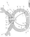
- a rotary internal combustion engine 10 known as a Wankel engine is schematically shown.
- the rotary engine 10 is used in a compound cycle engine system such as described in Lents et al.'s US patent No. 7,753,036 issued July 13, 2010 , as described in Julien et al.'s US patent No. 7,775,044 issued August 17, 2010 , or as described in published U.S. patent applications Nos. 2014/0020380 A1 and 2014/0020381 A1 .
- the compound cycle engine system may be used as a prime mover engine, such as on an aircraft or other vehicle, or in any other suitable application.
- the rotary engine 10 is used with a turbocharger without being compounded; in another embodiment, the rotary engine 10 is used without a turbocharger, with air at atmospheric pressure, as a stand-alone engine. In one embodiment, the rotary engine 10 may be applicable to land base systems including, but not limited to, generators.
- the engine 10 is shown and described herein as a Wankel engine as an example only. It is understood that the engine 10 may alternately be any other adequate type of internal combustion engine having a pilot subchamber for ignition, such as for example a reciprocating engine, or a rotary engine having a different configuration than that of a Wankel engine.
- the rotary engine may be a single or eccentric type rotary engine in which the rotor rotates about a fixed center of rotation.
- the rotary engine may be a sliding vane engine, such as described in US patent No. 5,524,587 issued June 11, 1996 or in US patent No. 5,522,356 issued June 4, 1996 .
- the rotary engine may be an oscillatory rotating engine, including two or more rotors rotating at different angular velocities, causing the distance between portions of the rotors to vary and as such the chamber volume to change.
- the rotary engine may be a planetary rotating engine having a different geometry than that of the Wankel engine, such as for example a planetary engine having a rotor cavity with an epitrochoid profile defining three lobes and a rotor with four apex portions. Examples of such non-Wankel rotary engines are shown in Applicant's U.S. application No. 13/750,523 filed January 25, 2013 , the entire contents of which is incorporated by reference herein. Other rotary engine geometries are also possible.
- the engine 10 generally includes at least one moveable body received in a corresponding internal cavity of an outer body to define at least one combustion chamber.
- the engine 10 may be a reciprocating engine with a plurality of internal cavities each receiving a moveable body in the form of a reciprocating piston.
- the engine 10 may alternately be a rotary engine with a plurality of internal cavities each receiving a moveable body on the form of a rotatable body or rotor.
- the engine 10 comprises an outer body 12 having at least one rotor cavity 20 (only one of which is shown) each defined by axially-spaced end walls 14 and a peripheral wall 18 extending therebetween, with a rotatable body or rotor 24 received in each cavity 20.
- the inner surface 19 of the peripheral wall 18 of each cavity 20 has a profile defining two lobes, which is preferably an epitrochoid.
- the outer body 12 may be integral or defined by a plurality of body portions each defining a respective one of the cavities 20 and receiving a respective one of the rotors 24.
- Each rotor 24 is received within the respective cavity 20, with the geometrical axis of the rotor 24 being offset from and parallel to the axis of the outer body 12.
- Each rotor 24 has axially spaced end faces 26 adjacent to the outer body end walls 14, and a peripheral face 28 extending therebetween.
- the peripheral face 28 defines three circumferentially-spaced apex portions 30 and a generally triangular profile with outwardly arched sides.
- the apex portions 30 are in sealing engagement with the inner surface of peripheral wall 18 to form three rotating working or combustion chambers 32 between the inner rotor 24 and outer body 12.
- a recess (not shown) is defined in the peripheral face 28 of the rotor 24 between each pair of adjacent apex portions 30, to form part of the corresponding chamber 32.
- Each rotor apex portion 30 has an apex seal 52 extending from one end face 26 to the other and protruding radially from the peripheral face 28. Each apex seal 52 is biased radially outwardly against the peripheral wall 18 through a respective spring. An end seal 54 engages each end of each apex seal 52, and is biased against the respective end wall 14 through a suitable spring.
- Each end face 26 of the rotor 24 has at least one arc-shaped face seal 60 running from each apex portion 30 to each adjacent apex portion 30, adjacent to but inwardly of the rotor periphery throughout its length.
- a spring urges each face seal 60 axially outwardly so that the face seal 60 projects axially away from the adjacent rotor end face 26 into sealing engagement with the adjacent end wall 14 of the cavity.
- Each face seal 60 is in sealing engagement with the end seal 54 adjacent each end thereof.
- each rotor 24 is journaled on an eccentric portion of a shaft and includes a phasing gear co-axial with the rotor axis, which is meshed with a fixed stator phasing gear secured to the outer body co-axially with the shaft.
- each rotor 24 may be journaled on a respective eccentric portion of a same shaft.
- the shaft rotates each rotor 24 and the meshed gears guide the rotor 24 to perform orbital revolutions within the respective rotor cavity 20.
- the shaft rotates three times for each complete rotation of the rotor 24 as it moves around the rotor cavity 20.
- Oil seals are provided around the phasing gear to prevent leakage flow of lubricating oil radially outwardly thereof between the respective rotor end face 26 and outer body end wall 14.
- At least one inlet port 44 is defined through one of the end walls 14 or the peripheral wall 18 for admitting air (atmospheric or compressed) into one of the working chambers 32
- at least one exhaust port 46 is defined through one of the end walls 14 or the peripheral wall 18 for discharge of the exhaust gases from the combustion chambers 32.
- the inlet and exhaust ports 44, 46 are positioned relative to each other and relative to the ignition member and fuel injectors (further described below) such that during each rotation of the rotor 24, each chamber 32 moves around the cavity 20 with a variable volume to undergo the four phases of intake, compression, expansion and exhaust, these phases being similar to the strokes in a reciprocating-type internal combustion engine having a four-stroke cycle.
- the inlet and exhaust ports 44, 46 are arranged such that the rotary engine 10 operates under the principle of the Miller or Atkinson cycle, with its volumetric compression ratio lower than its volumetric expansion ratio.
- the inlet and exhaust ports 44, 46 are arranged such that the volumetric compression and expansion ratios are equal or similar to one another.
- the engine 10 includes a pilot subchamber 72 for each rotor cavity 20, defined in the outer body 12, for pilot fuel injection and ignition.
- the pilot subchamber 72 is provided in an insert 34 received in a corresponding hole 36 defined through the peripheral wall 18 of the outer body 12.
- the insert 34 is retained to the peripheral wall 18 using any adequate type of connection, including, but not limited to, fasteners, welding, brazing, retention through a cover overlapping the insert 34 and connected to the peripheral wall 18, etc.
- the pilot subchamber 72 is directly defined in the peripheral wall 18.
- the insert body 34 has the entire pilot subchamber 72 defined therein, shown here with a circular cross-section.
- Other geometries are also possible, including but not limited to cylindrical, conical, frustoconical, wedge-shaped profiles, etc.
- the insert 34 includes at least one outlet opening 74 defined therein for communication with the cavity 20, and the subchamber 72 has a shape forming a reduced cross-section adjacent the opening(s) 74, such that the opening(s) 74 define a restriction to the flow between the subchamber 72 and the cavity 20.
- the opening(s) 74 may have various shapes and/or be defined by a pattern of multiple holes.
- the insert 34 shown is provided only as an example, and it is understood that other geometries and/or positions within the peripheral wall 18 are possible for the insert 34.
- the insert 34 is made of a material having a greater high temperature properties and/or lower thermal conductivity than that of the peripheral wall 18, which may be for example made of aluminum.
- the insert 34 is made of a nickel or cobalt based super alloy.
- the insert 34 may be omitted and the pilot subchamber 72 be directly defined in the peripheral wall 18 if the peripheral wall 18 is made of a material having sufficient heat resistance and adequate high temperature properties to resist the high temperatures within the subchamber 72.
- each rotor cavity 20 has a main injector elongated hole 40 defined therethrough, in communication with the rotor cavity 20 and spaced apart from the pilot subchamber 72.
- a main fuel injector 42 is received and retained within this corresponding hole 40, with the tip of the main injector 42 communicating with the cavity 20 at a point spaced apart from the pilot subchamber 72.
- the main injector 42 is located rearwardly of the pilot subchamber 72 with respect to the direction R of the rotor rotation and revolution, and is angled to direct fuel forwardly into each of the rotating chambers 32 sequentially with a tip hole pattern designed for an adequate spray.
- each rotor cavity 20 also has a pilot injector elongated hole 76 defined therethrough in communication with the subchamber 72.
- a pilot fuel injector 78 is received and retained within the corresponding hole 76, with the tip of the pilot injector 78 being in communication with the subchamber 72, for example by terminating in a corresponding opening defined in the insert 34 between the subchamber 72 and the pilot injector hole 76. It can be seen that the main injector 42 and pilot injector 78 are spaced apart from one another.
- the pilot injector 78 and main injector 42 of each rotor cavity 20 inject fuel, which in a particular embodiment is heavy fuel e.g. diesel, kerosene (jet fuel), equivalent biofuel, etc. into the chambers 32.
- the fuel may be any other adequate type of fuel suitable for injection as described, including non-heavy fuel such as for example gasoline or liquid hydrogen fuel.
- at least 0.5% and up to 20% of the fuel is injected through the pilot injector 78, and the remainder is injected through the main injector 42.
- at most 10% of the fuel is injected through the pilot injector 78.
- at most 5% of the fuel is injected through the pilot injector 78.
- the main injector 42 injects the fuel such that each rotating chamber 32 when in the combustion phase contains a lean mixture of air and fuel.
- each rotor cavity 20 and, in the embodiment shown, the insert body 34 have an ignition element elongated hole 82 defined therein in communication with the subchamber 72.
- An ignition element 84 is received and retained within the corresponding hole 82 and positioned to ignite fuel within the subchamber 72, e.g. with the tip of the ignition element 84 being received in the subchamber 72.
- the ignition element 84 is a glow plug.
- Other configurations are also possible, including for example having the ignition element 84 completely received within the insert 34, and/or ignition element(s) 84 of any other adequate type, including but not limited to plasma ignition, laser ignition, spark plug, microwave, other types of ignition elements, etc.
- the main fuel injector(s) 42 and the pilot fuel injector(s) 78 of the engine 10 are in fluid communication with a same common rail 100.
- the common rail 100 has an inlet 108 in fluid communication with a pump system 106.
- the pump system 106 includes a low pressure pump 110 located in or in fluid communication with a fuel source or fuel tank 112, and a high pressure pump 114 receiving the fuel from the low pressure pump 110 and feeding it to the inlet 108 of the common rail 100.
- the common rail 100 has an outlet 116 in selective fluid communication, directly or indirectly, with the fuel tank 112 such as to return an excess of fuel thereto.
- a metering or pressure regulating valve 118 is provided at the outlet 116 to regulate the flow of fuel therethrough.
- a pressure regulating mechanism regulates the fuel pressure in the common rail and may be provided in the pump system 106 (e.g. metering unit) and/or by the valve 118.
- an engine control unit 120 controls the pilot and main fuel injection through control of the high pressure pump 114 (e.g. actuation, fuel pressure and/or fuel flow), the valve 118 (e.g. position) and the fuel injectors 42, 78 (e.g. actuation of electronic valves controlling the injection pulses).
- the high pressure pump 114 e.g. actuation, fuel pressure and/or fuel flow
- the valve 118 e.g. position
- the fuel injectors 42, 78 e.g. actuation of electronic valves controlling the injection pulses.
- the engine 10 has a single moveable body, with a single main injector 42 and a single pilot injector 78 in fluid communication with the common rail 100.
- the engine 10 includes at least one additional moveable body, each having an additional main injector 42 and an additional pilot injector 78 (one being shown in dotted lines in Fig. 2 ) also in fluid communication with the same common rail 100.
- the fuel is combusted by pressurizing the fuel in the common rail 100, feeding the pilot injector(s) 78 with the common rail 100 to inject the fuel in the pilot subchamber(s) 72 where it is ignited and circulated into a respective combustion chamber 32, and feeding the main injector(s) 42 with the common rail 100 to inject the fuel into the combustion chamber 32.
- the pilot and main injections are thus performed spaced apart from one another.
- both the main and pilot injectors 42, 78 inject the fuel using the pressure provided in the common rail 100, e.g. without the use of pressure intensification mechanisms.
- a difference in fuel volume between the pilot and main injections may be provided by tuning the duration and/or number of injection pulses and/or by using a pilot injector 78 having a smaller open area, as defined by the tip openings through which the fuel is injected, than that of the main injector 42.
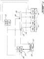
- the engine 10 includes multiple moveable bodies, and as such a plurality of main fuel injectors 42 and pilot fuel injectors 78 (three in the embodiment shown). All the main fuel injectors 42 are in fluid communication with a same common primary fuel conduit 202, while all the pilot fuel injectors 45 are in fluid communication with a same common secondary fuel conduit 204.
- a primary pressure regulating mechanism regulates the fuel pressure in the primary fuel conduit 202 while a secondary pressure regulating mechanism regulates a fuel pressure in the secondary conduit 204.
- the primary and secondary pressure regulating mechanisms are settable at different pressure values from one another such that the primary and secondary fuel conduits 202, 204 can provide fuel at different pressures.
- the primary and secondary conduits 202, 204 are separate chambers defined side by side in a same common rail 200.
- the inlet 208 of the common rail 200 and of the primary fuel conduit 202 is in fluid communication with a pump system 206 (e.g. single or multiple pump arrangement) providing for the primary pressure regulating mechanism (e.g. through a metering unit), by regulating the fuel flow from the pump system 206 to the primary conduit 202.
- a pump system 206 e.g. single or multiple pump arrangement
- the primary pressure regulating mechanism e.g. through a metering unit
- the primary and secondary conduits 202, 204 are in selective fluid communication with each other through a metering or pressure regulating valve 222 which is also in selective fluid communication with the fuel tank 112 such as to return an excess of fuel thereto.
- the valve 222 is a metering valve.
- the secondary conduit 204 has an outlet 216 (also corresponding to the outlet of the common rail 200) in selective fluid communication, directly or indirectly, with the fuel tank 112 such as to return an excess of fuel thereto.
- a second metering or pressure regulating valve 218 is provided at the outlet of the secondary conduit to regulate the flow of fuel therethrough.
- the pressure regulating mechanism of the secondary conduit 204 may be provided by the inlet valve 222 and/or the outlet valve 218.
- the engine control unit 120 controls the pilot and main fuel injection through control of the pump system 206 (e.g. actuation, fuel pressure and/or fuel flow), the valves 218, 222 (e.g. position) and the fuel injectors 42, 78 (e.g. actuation of electronic valves controlling the injection pulses).
- the pump system 206 e.g. actuation, fuel pressure and/or fuel flow
- the valves 218, 222 e.g. position
- the fuel injectors 42, 78 e.g. actuation of electronic valves controlling the injection pulses.
- the different pressures of the main and pilot injection allows for main and pilot injectors 42, 78 having a similar size and configuration to be used while still obtaining a smaller fuel volume in the pilot injection than in the main injection.
- the pilot injector 78 may have a smaller open area, as defined by the tip openings through which the fuel is injected, than that of the main injector 42.
- the fuel is combusted by pressurizing the fuel in the primary and secondary conduits 202, 204 to obtain different fuel pressures, feeding the pilot injectors 78 with the primary conduit 202 to inject fuel in the respective pilot subchamber 72 where it is ignited and circulated into a respective combustion chamber 32, and feeding the main injectors 42 with the secondary conduit 204 to inject fuel into the combustion chamber 32.
- the primary conduit 202 may be connected to the main injectors 42 and the secondary conduit 204 may be connected to the pilot injectors 78.
- the arrangement shown in Fig. 4 which falls outside the scope of the claimed invention is similar to the embodiment shown in Fig. 3 .
- the primary and secondary conduits 302, 304 are respectively defined by separate common rails.
- a first pump system 306 e.g. single or multiple pump arrangement
- a second pump system 307 e.g. single or multiple pump arrangement
- Each conduit 302, 304 has an outlet 315, 316 in selective fluid communication, directly or indirectly, with the fuel tank 112 such as to return an excess of fuel thereto.
- a metering or pressure regulating valve 322, 318 is provided at the outlet 315, 316 of each conduit 302, 304 to regulate the flow of fuel therethrough.
- the primary pressure regulating mechanism may thus provided in the first pump system 306 (e.g. metering unit) and/or by the first valve 322, while the secondary pressure regulating mechanism may be provided in the second pump system 307 (e.g. metering unit) and/or by the second valve 318.
- the engine control unit 120 controls the pilot and main fuel injection through control of the pump systems 306, 307 (e.g. actuation, fuel pressure and/or fuel flow), the valves 318, 322 (e.g. position) and the fuel injectors 42, 78 (e.g. actuation of electronic valves controlling the injection pulses).
- the pump system and valve associated with each of the conduits may be controlled by a different engine control unit.
Landscapes
- Engineering & Computer Science (AREA)
- Mechanical Engineering (AREA)
- General Engineering & Computer Science (AREA)
- Chemical & Material Sciences (AREA)
- Combustion & Propulsion (AREA)
- Fuel-Injection Apparatus (AREA)
- Combustion Methods Of Internal-Combustion Engines (AREA)
Claims (8)
- Verbrennungsmotor (10), Folgendes umfassend:mindestens zwei drehbare Körper (24);einen äußeren Körper (12), der einen entsprechenden internen Hohlraum (20) für jeden der drehbaren Körper definiert, wobei jeder der drehbaren Körper (24) dichtend und drehbar innerhalb des entsprechenden internen Hohlraums (20) aufgenommen ist, um mindestens eine Brennkammer (32) variablen Volumens zu definieren;den Motor (10), der für jeden der drehbaren Körper Folgendes beinhaltet:eine Vorsubkammer (72), die in dem äußeren Körper (12) definiert ist und in Verbindung mit dem entsprechenden internen Hohlraum (20) steht,eine Vorbrennstoffeinspritzung (78), die eine Spitze aufweist, die in Verbindung mit der Vorsubkammer (72) steht,ein Zündelement (84), das positioniert ist, Brennstoff innerhalb der Vorsubkammer (72) zu entzünden, undeine Hauptbrennstoffeinspritzung (42), die von der Vorbrennstoffeinspritzung (78) beabstandet ist und eine Spitze aufweist, die an einer Stelle in Verbindung mit dem internen Hohlraum (20) steht, die von der Vorsubkammer (72) beabstandet ist;eine gemeinsame erste Brennstoffleitung (202), die in Fluidverbindung mit jeder Hauptbrennstoffeinspritzung (42) steht;eine gemeinsame zweite Brennstoffleitung (204), die in Fluidverbindung mit jeder Vorbrennstoffeinspritzung (78) steht;einen ersten druckregulierenden Mechanismus (222) in Fluidverbindung mit der ersten Brennstoffleitung (202) zum Regulieren eines Brennstoffdrucks darin; undeinen zweiten druckregulierenden Mechanismus (218) in Fluidverbindung mit der zweiten Brennstoffleitung (204) zum Regulieren eines Brennstoffdrucks darin, wobei der druckregulierende Mechanismus in untereinander verschiedene Druckwerte einstellbar ist, wobei:
die erste und die zweite Leitung als verschiedene Kammern (202, 204) in einer gleichen gemeinsamen Schiene (200) in selektiver Fluidverbindung miteinander durch mindestens einen Teil des zweiten druckregulierenden Mechanismus definiert sind. - Motor nach Anspruch 1, wobei der erste druckregulierende Mechanismus mindestens zum Teil in einer Pumpe (206) bereitgestellt ist, die in Fluidverbindung mit einer Brennstoffquelle (112) und mit der ersten Brennstoffleitung (202) steht, wobei der zweite druckregulierende Mechanismus ein erstes mess- oder druckregulierendes Ventil (222), das die Kammern (202, 204) miteinander verbindet, und ein zweites mess- oder druckregulierendes Ventil (218) beinhaltet, durch welches ein Ausgang (216) der zweiten Leitung (204) in Fluidverbindung mit der Brennstoffquelle (112) steht.
- Motor nach Anspruch 2, wobei die Pumpe (206) und das erste und das zweite Ventil (222, 218) durch eine Motorsteuereinheit (120) betätigbar sind.
- Motor nach einem der vorstehenden Ansprüche, wobei jeder entsprechende interne Hohlraum (20) durch zwei axial beabstandete Endwände (14) und eine Umfangswand (18) definiert ist, die sich zwischen den Endwänden (14) erstreckt, und jeder der drehbaren Körper (24) ein Rotorkörper ist, der innerhalb des entsprechenden Hohlraums (20) in dichtendem Eingriff mit der Umfangswand und den Endwänden (18, 14) drehbar ist.
- Motor nach Anspruch 4, wobei jeder interne Hohlraum (20) eine epitrochoide Form mit zwei Nocken definiert, jeder Rotorkörper (24) drei umlaufend beabstandete Apexabschnitte (30) aufweist und die mindestens eine Brennkammer (32) drei sich drehende Kammern variablen Volumens beinhaltet, wobei der Rotorkörper (24) in Eingriff mit einem exzentrischen Abschnitt einer Welle steht, um zu sich zu drehen und Orbitaldrehungen innerhalb des Hohlraums (20) durchzuführen, wobei jeder der Apexabschnitte (30) in dichtendem Eingriff mit der Umfangswand (18) verbleibt und die Kammern (32) trennt.
- Verfahren zum Verbrennen von Brennstoff in einem Verbrennungsmotor (10) mit mindestens zwei drehbaren Körpern (24), wobei jeder mindestens eine Brennkammer (32) definiert, das Verfahren Folgendes umfassend:Druckbeaufschlagen von Brennstoff einer ersten Brennstoffleitung (202; 302) mit einem ersten Druck;Druckbeaufschlagen von Brennstoff in einer zweiten Brennstoffleitung (204; 304) mit einem zweiten Druck, der sich von dem ersten Druck unterscheidet, undfür jeden der drehbaren Körper (24) des Motors:Speisen einer entsprechenden Voreinspritzung (78) mit Brennstoff mit dem zweiten Druck von der zweiten Brennstoffleitung (204; 304), um Brennstoff in eine entsprechende Vorsubkammer (72) einzuspritzen,Entzünden des Brennstoffs innerhalb der entsprechenden Vorsubkammer (72),Zirkulieren des entzündeten Brennstoffs aus der entsprechenden Vorsubkammer (72) hinaus und in eine der Brennkammern (32) hinein, undSpeisen einer entsprechenden Haupteinspritzung (42) mit Brennstoff mit dem ersten Druck von der ersten Leitung (202; 302), um Brennstoff in eine der Brennkammern (32) einzuspritzen, die von der entsprechenden Subkammer (72) und der entsprechenden Voreinspritzung (78) beabstandet ist; wobei das Druckbeaufschlagen des Brennstoffs in der ersten Leitung das Druckbeaufschlagen des Brennstoffs in einer ersten Kammer (202) einer gemeinsamen Schiene (200) beinhaltet und das Druckbeaufschlagen des Brennstoffs in der zweiten Leitung das Zirkulieren des Brennstoffs von der ersten Kammer (202) in eine zweite Kammer (204) der gemeinsamen Schiene (200) und das Druckbeaufschlagen des Brennstoffs in der zweiten Kammer (204) beinhaltet.
- Verfahren nach Anspruch 6, wobei der Brennstoff schwerer Brennstoff ist.
- Verfahren nach Anspruch 6 oder 7, wobei das Druckbeaufschlagen des Brennstoffs in der ersten Leitung (202) und das Druckbeaufschlagen des Brennstoffs in der zweiten Leitung (204) das Regulieren des ersten und des zweiten Drucks mit mindestens einer Motorsteuereinheit (120) beinhaltet.
Priority Applications (1)
| Application Number | Priority Date | Filing Date | Title |
|---|---|---|---|
| PL14158964T PL2778367T3 (pl) | 2013-03-12 | 2014-03-11 | Silnik spalinowy z wtryskiem wstępnym i wtryskiem głównym |
Applications Claiming Priority (1)
| Application Number | Priority Date | Filing Date | Title |
|---|---|---|---|
| US13/796,216 US9399947B2 (en) | 2013-03-12 | 2013-03-12 | Internal combustion engine with pilot and main injection |
Publications (3)
| Publication Number | Publication Date |
|---|---|
| EP2778367A2 EP2778367A2 (de) | 2014-09-17 |
| EP2778367A3 EP2778367A3 (de) | 2015-03-04 |
| EP2778367B1 true EP2778367B1 (de) | 2019-05-01 |
Family
ID=50239522
Family Applications (1)
| Application Number | Title | Priority Date | Filing Date |
|---|---|---|---|
| EP14158964.8A Active EP2778367B1 (de) | 2013-03-12 | 2014-03-11 | Verbrennungsmotor mit Vor- und Haupteinspritzung |
Country Status (5)
| Country | Link |
|---|---|
| US (2) | US9399947B2 (de) |
| EP (1) | EP2778367B1 (de) |
| CA (1) | CA2844183C (de) |
| ES (1) | ES2731157T3 (de) |
| PL (1) | PL2778367T3 (de) |
Families Citing this family (22)
| Publication number | Priority date | Publication date | Assignee | Title |
|---|---|---|---|---|
| US10557407B2 (en) | 2011-07-28 | 2020-02-11 | Pratt & Whitney Canada Corp. | Rotary internal combustion engine with pilot subchamber |
| US9528434B1 (en) | 2011-07-28 | 2016-12-27 | Pratt & Whitney Canada Corp. | Rotary internal combustion engine with pilot subchamber |
| US9038594B2 (en) | 2011-07-28 | 2015-05-26 | Pratt & Whitney Canada Corp. | Rotary internal combustion engine with pilot subchamber |
| US10544732B2 (en) | 2011-07-28 | 2020-01-28 | Pratt & Whitney Canada Corp. | Rotary internal combustion engine with removable subchamber insert |
| US9200563B2 (en) | 2013-03-12 | 2015-12-01 | Pratt & Whitney Canada Corp. | Internal combustion engine with common rail pilot and main injection |
| US10584639B2 (en) | 2014-08-18 | 2020-03-10 | Woodward, Inc. | Torch igniter |
| US9896998B2 (en) | 2015-02-20 | 2018-02-20 | Pratt & Whitney Canada Corp. | Compound engine assembly with modulated flow |
| US9797297B2 (en) | 2015-02-20 | 2017-10-24 | Pratt & Whitney Canada Corp. | Compound engine assembly with common inlet |
| US9879591B2 (en) | 2015-02-20 | 2018-01-30 | Pratt & Whitney Canada Corp. | Engine intake assembly with selector valve |
| US9932892B2 (en) | 2015-02-20 | 2018-04-03 | Pratt & Whitney Canada Corp. | Compound engine assembly with coaxial compressor and offset turbine section |
| EP3109459B1 (de) * | 2015-06-23 | 2021-01-06 | MWI Micro Wave Ignition AG | Rotationskolben-verbrennungsmotor |
| US10041402B2 (en) | 2016-05-12 | 2018-08-07 | Pratt & Whitney Canada Corp. | Internal combustion engine with split pilot injection |
| US10302056B2 (en) | 2016-06-29 | 2019-05-28 | Ge Global Sourcing Llc | Systems and methods for fuel injector control |
| US10815877B2 (en) * | 2017-01-18 | 2020-10-27 | Pratt & Whitney Canada Corp. | Method of operating a rotary engine |
| US10145291B1 (en) * | 2017-10-10 | 2018-12-04 | Pratt & Whitney Canada Corp. | Rotary engine and method of combusting fuel |
| US10801394B2 (en) | 2017-11-29 | 2020-10-13 | Pratt & Whitney Canada Corp. | Rotary engine with pilot subchambers |
| JP7102755B2 (ja) * | 2018-02-02 | 2022-07-20 | マツダ株式会社 | エンジンの燃料供給装置 |
| US11421601B2 (en) | 2019-03-28 | 2022-08-23 | Woodward, Inc. | Second stage combustion for igniter |
| US11092126B2 (en) * | 2019-09-03 | 2021-08-17 | Pratt & Whitney Canada Corp. | Common-rail fuel system with ejector pump and method of use thereof |
| WO2021262853A1 (en) | 2020-06-23 | 2021-12-30 | Woodward, Inc. | Ignition system for power generation engine |
| CN112664314B (zh) * | 2020-07-29 | 2021-10-08 | 华中科技大学 | 一种拓扑转子发动机 |
| EP4290061B1 (de) | 2022-06-06 | 2026-03-25 | Volvo Construction Equipment AB | Kraftstoffinjektionssystem und -verfahren |
Family Cites Families (53)
| Publication number | Priority date | Publication date | Assignee | Title |
|---|---|---|---|---|
| US3077867A (en) * | 1958-10-07 | 1963-02-19 | Nsu Motorenwerke Ag | Multiple arrangement of rotary combustion engines |
| US3062435A (en) * | 1959-11-17 | 1962-11-06 | Curtiss Wright Corp | Multi-unit rotary engine |
| US3476092A (en) * | 1966-11-16 | 1969-11-04 | Toyo Kogyo Co | Multi-unit rotary piston internal combustion engine |
| US3528084A (en) * | 1967-12-02 | 1970-09-08 | Daimler Benz Ag | Rotary piston internal combustion engine |
| US3744940A (en) * | 1971-12-16 | 1973-07-10 | Curtiss Wright Corp | Rotary expansion engine of the wankel type |
| US3958538A (en) | 1972-05-15 | 1976-05-25 | Nissan Motor Co., Ltd. | Gaseous ignition system for internal combustion engine |
| JPS4917910U (de) | 1972-05-24 | 1974-02-15 | ||
| US3861361A (en) * | 1973-11-29 | 1975-01-21 | Gen Motors Corp | Rotary engine with piston scavenged precombustion chambers |
| US3894518A (en) | 1973-12-12 | 1975-07-15 | Curtiss Wright Corp | Stratified charge rotary engine with dual fuel injection |
| US3960115A (en) | 1974-10-04 | 1976-06-01 | Curtiss-Wright Corporation | Stratified charge rotary engine (method of operation) |
| US3987759A (en) * | 1975-06-03 | 1976-10-26 | Curtiss-Wright Corporation | Stratified charge rotary engine with variable spray angle fuel nozzle |
| US4029058A (en) | 1976-03-15 | 1977-06-14 | Curtiss-Wright Corporation | Stratified charge rotary engine with side housing fuel injection |
| US4047856A (en) * | 1976-03-18 | 1977-09-13 | Hoffman Ralph M | Rotary steam engine |
| US4070995A (en) | 1976-06-11 | 1978-01-31 | Curtiss-Wright Corporation | Rotary engine with combustion gas flow-back for diesel operation |
| US4090822A (en) * | 1977-01-28 | 1978-05-23 | Curtiss-Wright Corporation | Multi-sectional driveshaft for a rotary piston mechanism |
| US4091789A (en) | 1977-02-11 | 1978-05-30 | Curtiss-Wright Corporation | Stratified charge fuel injection system for rotary engine |
| US4085712A (en) | 1977-02-14 | 1978-04-25 | Curtiss-Wright Corporation | Rotary engine with pilot and main fuel nozzles downstream of top center |
| US4083329A (en) * | 1977-02-14 | 1978-04-11 | Curtiss-Wright Corporation | Rotary engine with a pilot fuel nozzle downstream of top center |
| US4135485A (en) * | 1977-06-21 | 1979-01-23 | Curtiss-Wright Corporation | Split-multi-unit rotary combustion engine |
| US4132513A (en) * | 1977-09-26 | 1979-01-02 | Curtiss-Wright Corporation | Rotary engine counterweight system |
| US4187825A (en) * | 1977-10-17 | 1980-02-12 | Curtiss-Wright Corporation | Pilot fuel ignited stratified charge rotary combustion engine and fuel injector therefor |
| US4239023A (en) | 1978-12-07 | 1980-12-16 | Ford Motor Company | Fuel injection system for dual combustion chamber engine |
| US4403928A (en) * | 1981-03-30 | 1983-09-13 | Curtiss-Wright Corporation | Multi-unit rotary mechanism |
| US4759324A (en) * | 1985-12-27 | 1988-07-26 | Mazda Motor Corporation | Intake system for rotary piston engine |
| US4681073A (en) | 1986-02-05 | 1987-07-21 | Deere & Company | Fuel injection control valve |
| US4969429A (en) * | 1989-10-02 | 1990-11-13 | John Deere Technologies International, Inc. | Lube oil control system for turbocharged rotary piston engine |
| US5090378A (en) * | 1991-02-22 | 1992-02-25 | The Cessna Aircraft Company | Dual nozzle single pump fuel injection system |
| US5410998A (en) * | 1991-05-21 | 1995-05-02 | Paul; Marius A. | Continuous external heat engine |
| US5522356A (en) | 1992-09-04 | 1996-06-04 | Spread Spectrum | Method and apparatus for transferring heat energy from engine housing to expansion fluid employed in continuous combustion, pinned vane type, integrated rotary compressor-expander engine system |
| US5313924A (en) | 1993-03-08 | 1994-05-24 | Chrysler Corporation | Fuel injection system and method for a diesel or stratified charge engine |
| US5524587A (en) | 1995-03-03 | 1996-06-11 | Mallen Research Ltd. Partnership | Sliding vane engine |
| JP3772518B2 (ja) | 1998-02-27 | 2006-05-10 | いすゞ自動車株式会社 | エンジンの運転制御装置 |
| US6302080B1 (en) | 1998-07-31 | 2001-10-16 | Denso Corporation | Fuel injection system having pre-injection and main injection |
| US6568369B1 (en) | 2000-12-05 | 2003-05-27 | Caterpillar Inc | Common rail injector with separately controlled pilot and main injection |
| EP1611330A4 (de) * | 2003-01-22 | 2010-06-16 | Abraham E Karem | Ausfalltoleranter verbrennungsmotor |
| EP1611331B1 (de) | 2003-02-24 | 2010-09-01 | Pratt & Whitney Canada Corp. | Integrierter Turboverbund-Rotationsmotor mit niedrigem volumetrischen Verdichtungsverhältnis |
| US7219655B2 (en) * | 2003-02-28 | 2007-05-22 | Caterpillar Inc | Fuel injection system including two common rails for injecting fuel at two independently controlled pressures |
| US7392491B2 (en) | 2003-03-14 | 2008-06-24 | Combustion Dynamics Corp. | Systems and methods for operating an electromagnetic actuator |
| US6973921B2 (en) * | 2003-12-12 | 2005-12-13 | Caterpillar Inc. | Fuel pumping system and method |
| JP4552694B2 (ja) * | 2005-03-02 | 2010-09-29 | トヨタ自動車株式会社 | 車両の燃料供給装置 |
| JP4148233B2 (ja) | 2005-03-29 | 2008-09-10 | トヨタ自動車株式会社 | エンジンの燃料噴射制御装置 |
| IL170165A (en) * | 2005-08-08 | 2010-12-30 | Haim Rom | Wankel and similar rotary engines |
| US7431017B2 (en) * | 2006-05-24 | 2008-10-07 | Caterpillar Inc. | Multi-source fuel system having closed loop pressure control |
| JP4582064B2 (ja) | 2006-07-21 | 2010-11-17 | 株式会社デンソー | 燃料噴射制御装置 |
| JP4462287B2 (ja) | 2007-04-23 | 2010-05-12 | 株式会社デンソー | 内燃機関の異常診断装置及び内燃機関の制御システム |
| US7753036B2 (en) | 2007-07-02 | 2010-07-13 | United Technologies Corporation | Compound cycle rotary engine |
| US9038594B2 (en) | 2011-07-28 | 2015-05-26 | Pratt & Whitney Canada Corp. | Rotary internal combustion engine with pilot subchamber |
| US9512721B2 (en) | 2012-07-20 | 2016-12-06 | Pratt & Whitney Canada Corp. | Compound cycle engine |
| US9194232B2 (en) | 2012-07-20 | 2015-11-24 | Pratt & Whitney Canada Corp. | Compound cycle engine |
| DE102012214261A1 (de) * | 2012-08-10 | 2014-05-22 | Bayerische Motoren Werke Aktiengesellschaft | Brennkraftmaschine mit einem ersten und einem zweiten Injektor |
| US9353680B2 (en) | 2013-03-04 | 2016-05-31 | Pratt & Whitney Canada Corp. | Rotary internal combustion engine with pilot subchamber |
| US10280830B2 (en) | 2013-03-08 | 2019-05-07 | Pratt & Whitney Canada Corp. | System for pilot subchamber temperature control |
| WO2015025079A1 (en) * | 2013-08-20 | 2015-02-26 | Wärtsilä Finland Oy | Fuel injection system and method for operating a multi-fuel piston engine |
-
2013
- 2013-03-12 US US13/796,216 patent/US9399947B2/en active Active
-
2014
- 2014-02-27 CA CA2844183A patent/CA2844183C/en active Active
- 2014-03-11 PL PL14158964T patent/PL2778367T3/pl unknown
- 2014-03-11 EP EP14158964.8A patent/EP2778367B1/de active Active
- 2014-03-11 ES ES14158964T patent/ES2731157T3/es active Active
-
2016
- 2016-06-21 US US15/188,378 patent/US9708966B2/en active Active
Non-Patent Citations (1)
| Title |
|---|
| None * |
Also Published As
| Publication number | Publication date |
|---|---|
| CA2844183C (en) | 2021-01-19 |
| EP2778367A2 (de) | 2014-09-17 |
| EP2778367A3 (de) | 2015-03-04 |
| ES2731157T3 (es) | 2019-11-14 |
| US20160298530A1 (en) | 2016-10-13 |
| US9399947B2 (en) | 2016-07-26 |
| PL2778367T3 (pl) | 2019-11-29 |
| US20140261293A1 (en) | 2014-09-18 |
| CA2844183A1 (en) | 2014-09-12 |
| US9708966B2 (en) | 2017-07-18 |
Similar Documents
| Publication | Publication Date | Title |
|---|---|---|
| US10267217B2 (en) | Internal combustion engine with common rail injection | |
| EP2778367B1 (de) | Verbrennungsmotor mit Vor- und Haupteinspritzung | |
| US10968820B2 (en) | Method of combusting fuel in a rotary internal combustion engine with pilot subchamber and ignition element | |
| EP2551448B1 (de) | Drehverbrennungsmotor mit pilotenunterkammer und verfahren zur brennstoffeinspritzung | |
| EP2775117B1 (de) | Drehverbrennungsmotor mit Pilotenunterkammer | |
| US11306651B2 (en) | Method of operating an internal combustion engine | |
| CA2991582C (en) | Method of operating a rotary engine |
Legal Events
| Date | Code | Title | Description |
|---|---|---|---|
| 17P | Request for examination filed |
Effective date: 20140311 |
|
| AK | Designated contracting states |
Kind code of ref document: A2 Designated state(s): AL AT BE BG CH CY CZ DE DK EE ES FI FR GB GR HR HU IE IS IT LI LT LU LV MC MK MT NL NO PL PT RO RS SE SI SK SM TR |
|
| AX | Request for extension of the european patent |
Extension state: BA ME |
|
| PUAI | Public reference made under article 153(3) epc to a published international application that has entered the european phase |
Free format text: ORIGINAL CODE: 0009012 |
|
| PUAL | Search report despatched |
Free format text: ORIGINAL CODE: 0009013 |
|
| AK | Designated contracting states |
Kind code of ref document: A3 Designated state(s): AL AT BE BG CH CY CZ DE DK EE ES FI FR GB GR HR HU IE IS IT LI LT LU LV MC MK MT NL NO PL PT RO RS SE SI SK SM TR |
|
| AX | Request for extension of the european patent |
Extension state: BA ME |
|
| RIC1 | Information provided on ipc code assigned before grant |
Ipc: F02M 63/02 20060101ALI20150127BHEP Ipc: F02B 53/10 20060101AFI20150127BHEP Ipc: F02B 19/10 20060101ALI20150127BHEP |
|
| R17P | Request for examination filed (corrected) |
Effective date: 20150904 |
|
| RBV | Designated contracting states (corrected) |
Designated state(s): AL AT BE BG CH CY CZ DE DK EE ES FI FR GB GR HR HU IE IS IT LI LT LU LV MC MK MT NL NO PL PT RO RS SE SI SK SM TR |
|
| GRAP | Despatch of communication of intention to grant a patent |
Free format text: ORIGINAL CODE: EPIDOSNIGR1 |
|
| STAA | Information on the status of an ep patent application or granted ep patent |
Free format text: STATUS: GRANT OF PATENT IS INTENDED |
|
| RIC1 | Information provided on ipc code assigned before grant |
Ipc: F02B 19/10 20060101ALI20180830BHEP Ipc: F02M 63/02 20060101ALI20180830BHEP Ipc: F02B 53/10 20060101AFI20180830BHEP |
|
| INTG | Intention to grant announced |
Effective date: 20180925 |
|
| GRAS | Grant fee paid |
Free format text: ORIGINAL CODE: EPIDOSNIGR3 |
|
| GRAA | (expected) grant |
Free format text: ORIGINAL CODE: 0009210 |
|
| STAA | Information on the status of an ep patent application or granted ep patent |
Free format text: STATUS: THE PATENT HAS BEEN GRANTED |
|
| AK | Designated contracting states |
Kind code of ref document: B1 Designated state(s): AL AT BE BG CH CY CZ DE DK EE ES FI FR GB GR HR HU IE IS IT LI LT LU LV MC MK MT NL NO PL PT RO RS SE SI SK SM TR |
|
| REG | Reference to a national code |
Ref country code: GB Ref legal event code: FG4D |
|
| REG | Reference to a national code |
Ref country code: CH Ref legal event code: EP Ref country code: AT Ref legal event code: REF Ref document number: 1127208 Country of ref document: AT Kind code of ref document: T Effective date: 20190515 |
|
| REG | Reference to a national code |
Ref country code: DE Ref legal event code: R096 Ref document number: 602014045610 Country of ref document: DE |
|
| REG | Reference to a national code |
Ref country code: IE Ref legal event code: FG4D |
|
| REG | Reference to a national code |
Ref country code: CH Ref legal event code: NV Representative=s name: VALIPAT S.A. C/O BOVARD SA NEUCHATEL, CH |
|
| REG | Reference to a national code |
Ref country code: NL Ref legal event code: MP Effective date: 20190501 |
|
| REG | Reference to a national code |
Ref country code: LT Ref legal event code: MG4D |
|
| PG25 | Lapsed in a contracting state [announced via postgrant information from national office to epo] |
Ref country code: AL Free format text: LAPSE BECAUSE OF FAILURE TO SUBMIT A TRANSLATION OF THE DESCRIPTION OR TO PAY THE FEE WITHIN THE PRESCRIBED TIME-LIMIT Effective date: 20190501 Ref country code: SE Free format text: LAPSE BECAUSE OF FAILURE TO SUBMIT A TRANSLATION OF THE DESCRIPTION OR TO PAY THE FEE WITHIN THE PRESCRIBED TIME-LIMIT Effective date: 20190501 Ref country code: PT Free format text: LAPSE BECAUSE OF FAILURE TO SUBMIT A TRANSLATION OF THE DESCRIPTION OR TO PAY THE FEE WITHIN THE PRESCRIBED TIME-LIMIT Effective date: 20190901 Ref country code: NO Free format text: LAPSE BECAUSE OF FAILURE TO SUBMIT A TRANSLATION OF THE DESCRIPTION OR TO PAY THE FEE WITHIN THE PRESCRIBED TIME-LIMIT Effective date: 20190801 Ref country code: HR Free format text: LAPSE BECAUSE OF FAILURE TO SUBMIT A TRANSLATION OF THE DESCRIPTION OR TO PAY THE FEE WITHIN THE PRESCRIBED TIME-LIMIT Effective date: 20190501 Ref country code: FI Free format text: LAPSE BECAUSE OF FAILURE TO SUBMIT A TRANSLATION OF THE DESCRIPTION OR TO PAY THE FEE WITHIN THE PRESCRIBED TIME-LIMIT Effective date: 20190501 Ref country code: LT Free format text: LAPSE BECAUSE OF FAILURE TO SUBMIT A TRANSLATION OF THE DESCRIPTION OR TO PAY THE FEE WITHIN THE PRESCRIBED TIME-LIMIT Effective date: 20190501 Ref country code: NL Free format text: LAPSE BECAUSE OF FAILURE TO SUBMIT A TRANSLATION OF THE DESCRIPTION OR TO PAY THE FEE WITHIN THE PRESCRIBED TIME-LIMIT Effective date: 20190501 |
|
| REG | Reference to a national code |
Ref country code: ES Ref legal event code: FG2A Ref document number: 2731157 Country of ref document: ES Kind code of ref document: T3 Effective date: 20191114 |
|
| PG25 | Lapsed in a contracting state [announced via postgrant information from national office to epo] |
Ref country code: LV Free format text: LAPSE BECAUSE OF FAILURE TO SUBMIT A TRANSLATION OF THE DESCRIPTION OR TO PAY THE FEE WITHIN THE PRESCRIBED TIME-LIMIT Effective date: 20190501 Ref country code: BG Free format text: LAPSE BECAUSE OF FAILURE TO SUBMIT A TRANSLATION OF THE DESCRIPTION OR TO PAY THE FEE WITHIN THE PRESCRIBED TIME-LIMIT Effective date: 20190801 Ref country code: RS Free format text: LAPSE BECAUSE OF FAILURE TO SUBMIT A TRANSLATION OF THE DESCRIPTION OR TO PAY THE FEE WITHIN THE PRESCRIBED TIME-LIMIT Effective date: 20190501 Ref country code: GR Free format text: LAPSE BECAUSE OF FAILURE TO SUBMIT A TRANSLATION OF THE DESCRIPTION OR TO PAY THE FEE WITHIN THE PRESCRIBED TIME-LIMIT Effective date: 20190802 |
|
| PG25 | Lapsed in a contracting state [announced via postgrant information from national office to epo] |
Ref country code: IS Free format text: LAPSE BECAUSE OF FAILURE TO SUBMIT A TRANSLATION OF THE DESCRIPTION OR TO PAY THE FEE WITHIN THE PRESCRIBED TIME-LIMIT Effective date: 20190901 |
|
| PG25 | Lapsed in a contracting state [announced via postgrant information from national office to epo] |
Ref country code: DK Free format text: LAPSE BECAUSE OF FAILURE TO SUBMIT A TRANSLATION OF THE DESCRIPTION OR TO PAY THE FEE WITHIN THE PRESCRIBED TIME-LIMIT Effective date: 20190501 Ref country code: SK Free format text: LAPSE BECAUSE OF FAILURE TO SUBMIT A TRANSLATION OF THE DESCRIPTION OR TO PAY THE FEE WITHIN THE PRESCRIBED TIME-LIMIT Effective date: 20190501 Ref country code: EE Free format text: LAPSE BECAUSE OF FAILURE TO SUBMIT A TRANSLATION OF THE DESCRIPTION OR TO PAY THE FEE WITHIN THE PRESCRIBED TIME-LIMIT Effective date: 20190501 Ref country code: RO Free format text: LAPSE BECAUSE OF FAILURE TO SUBMIT A TRANSLATION OF THE DESCRIPTION OR TO PAY THE FEE WITHIN THE PRESCRIBED TIME-LIMIT Effective date: 20190501 |
|
| REG | Reference to a national code |
Ref country code: DE Ref legal event code: R097 Ref document number: 602014045610 Country of ref document: DE |
|
| PG25 | Lapsed in a contracting state [announced via postgrant information from national office to epo] |
Ref country code: SM Free format text: LAPSE BECAUSE OF FAILURE TO SUBMIT A TRANSLATION OF THE DESCRIPTION OR TO PAY THE FEE WITHIN THE PRESCRIBED TIME-LIMIT Effective date: 20190501 |
|
| PLBE | No opposition filed within time limit |
Free format text: ORIGINAL CODE: 0009261 |
|
| STAA | Information on the status of an ep patent application or granted ep patent |
Free format text: STATUS: NO OPPOSITION FILED WITHIN TIME LIMIT |
|
| PG25 | Lapsed in a contracting state [announced via postgrant information from national office to epo] |
Ref country code: TR Free format text: LAPSE BECAUSE OF FAILURE TO SUBMIT A TRANSLATION OF THE DESCRIPTION OR TO PAY THE FEE WITHIN THE PRESCRIBED TIME-LIMIT Effective date: 20190501 |
|
| 26N | No opposition filed |
Effective date: 20200204 |
|
| PG25 | Lapsed in a contracting state [announced via postgrant information from national office to epo] |
Ref country code: SI Free format text: LAPSE BECAUSE OF FAILURE TO SUBMIT A TRANSLATION OF THE DESCRIPTION OR TO PAY THE FEE WITHIN THE PRESCRIBED TIME-LIMIT Effective date: 20190501 |
|
| PG25 | Lapsed in a contracting state [announced via postgrant information from national office to epo] |
Ref country code: MC Free format text: LAPSE BECAUSE OF FAILURE TO SUBMIT A TRANSLATION OF THE DESCRIPTION OR TO PAY THE FEE WITHIN THE PRESCRIBED TIME-LIMIT Effective date: 20190501 |
|
| REG | Reference to a national code |
Ref country code: BE Ref legal event code: MM Effective date: 20200331 |
|
| PG25 | Lapsed in a contracting state [announced via postgrant information from national office to epo] |
Ref country code: LU Free format text: LAPSE BECAUSE OF NON-PAYMENT OF DUE FEES Effective date: 20200311 |
|
| PG25 | Lapsed in a contracting state [announced via postgrant information from national office to epo] |
Ref country code: IE Free format text: LAPSE BECAUSE OF NON-PAYMENT OF DUE FEES Effective date: 20200311 |
|
| PG25 | Lapsed in a contracting state [announced via postgrant information from national office to epo] |
Ref country code: BE Free format text: LAPSE BECAUSE OF NON-PAYMENT OF DUE FEES Effective date: 20200331 |
|
| REG | Reference to a national code |
Ref country code: AT Ref legal event code: UEP Ref document number: 1127208 Country of ref document: AT Kind code of ref document: T Effective date: 20190501 |
|
| PG25 | Lapsed in a contracting state [announced via postgrant information from national office to epo] |
Ref country code: MT Free format text: LAPSE BECAUSE OF FAILURE TO SUBMIT A TRANSLATION OF THE DESCRIPTION OR TO PAY THE FEE WITHIN THE PRESCRIBED TIME-LIMIT Effective date: 20190501 Ref country code: CY Free format text: LAPSE BECAUSE OF FAILURE TO SUBMIT A TRANSLATION OF THE DESCRIPTION OR TO PAY THE FEE WITHIN THE PRESCRIBED TIME-LIMIT Effective date: 20190501 |
|
| PG25 | Lapsed in a contracting state [announced via postgrant information from national office to epo] |
Ref country code: MK Free format text: LAPSE BECAUSE OF FAILURE TO SUBMIT A TRANSLATION OF THE DESCRIPTION OR TO PAY THE FEE WITHIN THE PRESCRIBED TIME-LIMIT Effective date: 20190501 |
|
| P01 | Opt-out of the competence of the unified patent court (upc) registered |
Effective date: 20230530 |
|
| PGFP | Annual fee paid to national office [announced via postgrant information from national office to epo] |
Ref country code: PL Payment date: 20250225 Year of fee payment: 12 Ref country code: CZ Payment date: 20250225 Year of fee payment: 12 |
|
| PGFP | Annual fee paid to national office [announced via postgrant information from national office to epo] |
Ref country code: ES Payment date: 20250401 Year of fee payment: 12 |
|
| PGFP | Annual fee paid to national office [announced via postgrant information from national office to epo] |
Ref country code: CH Payment date: 20250401 Year of fee payment: 12 |
|
| REG | Reference to a national code |
Ref country code: CH Ref legal event code: U11 Free format text: ST27 STATUS EVENT CODE: U-0-0-U10-U11 (AS PROVIDED BY THE NATIONAL OFFICE) Effective date: 20260401 |
|
| PGFP | Annual fee paid to national office [announced via postgrant information from national office to epo] |
Ref country code: GB Payment date: 20260220 Year of fee payment: 13 |
|
| PGFP | Annual fee paid to national office [announced via postgrant information from national office to epo] |
Ref country code: DE Payment date: 20260219 Year of fee payment: 13 |
|
| PGFP | Annual fee paid to national office [announced via postgrant information from national office to epo] |
Ref country code: AT Payment date: 20260223 Year of fee payment: 13 |
|
| PGFP | Annual fee paid to national office [announced via postgrant information from national office to epo] |
Ref country code: IT Payment date: 20260219 Year of fee payment: 13 |
|
| PGFP | Annual fee paid to national office [announced via postgrant information from national office to epo] |
Ref country code: FR Payment date: 20260219 Year of fee payment: 13 |