EP2778348A1 - Steam turbine - Google Patents
Steam turbine Download PDFInfo
- Publication number
- EP2778348A1 EP2778348A1 EP14159221.2A EP14159221A EP2778348A1 EP 2778348 A1 EP2778348 A1 EP 2778348A1 EP 14159221 A EP14159221 A EP 14159221A EP 2778348 A1 EP2778348 A1 EP 2778348A1
- Authority
- EP
- European Patent Office
- Prior art keywords
- stationary blade
- outer ring
- steam turbine
- steam
- diaphragm
- Prior art date
- Legal status (The legal status is an assumption and is not a legal conclusion. Google has not performed a legal analysis and makes no representation as to the accuracy of the status listed.)
- Granted
Links
Images






Classifications
-
- F—MECHANICAL ENGINEERING; LIGHTING; HEATING; WEAPONS; BLASTING
- F01—MACHINES OR ENGINES IN GENERAL; ENGINE PLANTS IN GENERAL; STEAM ENGINES
- F01D—NON-POSITIVE DISPLACEMENT MACHINES OR ENGINES, e.g. STEAM TURBINES
- F01D9/00—Stators
- F01D9/02—Nozzles; Nozzle boxes; Stator blades; Guide conduits, e.g. individual nozzles
- F01D9/04—Nozzles; Nozzle boxes; Stator blades; Guide conduits, e.g. individual nozzles forming ring or sector
-
- F—MECHANICAL ENGINEERING; LIGHTING; HEATING; WEAPONS; BLASTING
- F01—MACHINES OR ENGINES IN GENERAL; ENGINE PLANTS IN GENERAL; STEAM ENGINES
- F01D—NON-POSITIVE DISPLACEMENT MACHINES OR ENGINES, e.g. STEAM TURBINES
- F01D25/00—Component parts, details, or accessories, not provided for in, or of interest apart from, other groups
- F01D25/32—Collecting of condensation water; Drainage ; Removing solid particles
-
- F—MECHANICAL ENGINEERING; LIGHTING; HEATING; WEAPONS; BLASTING
- F01—MACHINES OR ENGINES IN GENERAL; ENGINE PLANTS IN GENERAL; STEAM ENGINES
- F01D—NON-POSITIVE DISPLACEMENT MACHINES OR ENGINES, e.g. STEAM TURBINES
- F01D5/00—Blades; Blade-carrying members; Heating, heat-insulating, cooling or antivibration means on the blades or the members
- F01D5/12—Blades
- F01D5/28—Selecting particular materials; Particular measures relating thereto; Measures against erosion or corrosion
-
- F—MECHANICAL ENGINEERING; LIGHTING; HEATING; WEAPONS; BLASTING
- F01—MACHINES OR ENGINES IN GENERAL; ENGINE PLANTS IN GENERAL; STEAM ENGINES
- F01D—NON-POSITIVE DISPLACEMENT MACHINES OR ENGINES, e.g. STEAM TURBINES
- F01D9/00—Stators
- F01D9/02—Nozzles; Nozzle boxes; Stator blades; Guide conduits, e.g. individual nozzles
- F01D9/04—Nozzles; Nozzle boxes; Stator blades; Guide conduits, e.g. individual nozzles forming ring or sector
- F01D9/042—Nozzles; Nozzle boxes; Stator blades; Guide conduits, e.g. individual nozzles forming ring or sector fixing blades to stators
-
- F—MECHANICAL ENGINEERING; LIGHTING; HEATING; WEAPONS; BLASTING
- F05—INDEXING SCHEMES RELATING TO ENGINES OR PUMPS IN VARIOUS SUBCLASSES OF CLASSES F01-F04
- F05D—INDEXING SCHEME FOR ASPECTS RELATING TO NON-POSITIVE-DISPLACEMENT MACHINES OR ENGINES, GAS-TURBINES OR JET-PROPULSION PLANTS
- F05D2220/00—Application
- F05D2220/30—Application in turbines
- F05D2220/31—Application in turbines in steam turbines
-
- F—MECHANICAL ENGINEERING; LIGHTING; HEATING; WEAPONS; BLASTING
- F05—INDEXING SCHEMES RELATING TO ENGINES OR PUMPS IN VARIOUS SUBCLASSES OF CLASSES F01-F04
- F05D—INDEXING SCHEME FOR ASPECTS RELATING TO NON-POSITIVE-DISPLACEMENT MACHINES OR ENGINES, GAS-TURBINES OR JET-PROPULSION PLANTS
- F05D2230/00—Manufacture
- F05D2230/20—Manufacture essentially without removing material
- F05D2230/23—Manufacture essentially without removing material by permanently joining parts together
- F05D2230/232—Manufacture essentially without removing material by permanently joining parts together by welding
Definitions
- Embodiments described herein relate generally to a steam turbine.
- a steam turbine is used in power generation plants such as a nuclear power generation plant, a thermal power generation plant, a geothermal power generation plant.
- the steam turbine converts thermal energy of steam from high-pressure to low-pressure into a mechanical work. During this process, a temperature of the steam is lowered at a low-pressure part of the steam turbine, and a part of the steam condenses during an expansion work to increase wetness.
- the condensed moisture adheres or collides with a wall surface of a steam passage or a rotor blade of the steam turbine.
- slits are provided at a stationary blade of a stationary component and a surface of a nozzle diaphragm outer ring of the stationary component supporting the stationary blade, and the moisture adhered on the surface of the stationary component of the steam passage is collected.
- the stationary component where the slits are provided has a hollow structure. The moisture collected by the slits pass through a hollow part, and is exhausted from the steam passage toward outside of the steam turbine.
- the slits at the stationary blade and the surface of the nozzle diaphragm outer ring at the conventional steam turbine are formed to have a width of, for example, 1 mm or less. Accordingly, the slit is generally formed by electric discharge machining. However, there is a case when it is difficult to process the slit by the electric discharge machining because the nozzle diaphragm and so on become thick according to large-sizing of the steam turbine.
- FIG. 1 is a view illustrating a meridian cross section in a vertical direction of a steam turbine 10 according to a first embodiment.
- the steam turbine 10 includes a casing 20, and a turbine rotor 22 is provided to penetrate in the casing 20.
- Plural rotor blades 21 are implanted into the turbine rotor 22 in a circumferential direction to make up a rotor blade cascade.
- the rotor blade cascades are provided in plural stages in a turbine rotor axial direction.
- the turbine rotor 22 is rotatably supported by a not-illustrated rotor bearing.
- a diaphragm outer ring 23 is arranged at an inner side of the casing 20.
- a diaphragm inner ring 24 is arranged at an inner side of the diaphragm outer ring 23.
- Plural stationary blades 25 are supported between the diaphragm outer ring 23 and the diaphragm inner ring 24 in a circumferential direction to make up a stationary blade cascade.
- the stationary blade cascades are provided in plural stages to be arranged alternately with the rotor blade cascades in the turbine rotor axial direction.
- One turbine stage is made up of the stationary blade cascade and the rotor blade cascade positioning at an immediately downstream side of the stationary blade cascade.
- a gland sealing part 26 is provided between the turbine rotor 22 and the casing 20 so as to prevent leakage of steam toward outside.
- a sealing part 27 is provided between the turbine rotor 22 and the diaphragm inner ring 24 so as to prevent leakage of steam.
- a steam inlet pipe 28 to introduce the steam toward inside is provided at the steam turbine 10 while penetrating the casing 20.
- an exhaust flow passage is provided at a downstream side of a final turbine stage to exhaust the steam performing an expansion work at the turbine stage, though it is not illustrated. This exhaust flow passage is communicated with, for example, a condenser (not-illustrated).
- the final turbine stage is exemplified to be described as a turbine stage where the wet steam flows.
- the turbine stage where the wet steam flows is not limited to the final turbine stage, and there is a case when turbine stages at an upstream side than the final turbine stage may be included.
- a function to secure generated waterdroplet and water film is included in the turbine stage where the wet steam flows.
- FIG. 2 is a view illustrating a cross section of a part of the final turbine stage in the steam turbine 10 according to the first embodiment.
- FIG. 2 a cross section between the stationary blades 25 is illustrated, and a suction side of the stationary blade 25 is seen.
- FIG. 3 is a view illustrating an A-A cross section in FIG. 2 in which a part of the final turbine stage in the steam turbine 10 according to the first embodiment is illustrated.
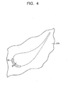
- FIG. 4 is a plan view illustrating a through hole 50 formed at the diaphragm outer ring 23 at the final turbine stage in the steam turbine 10 according to the first embodiment.
- a position (a position at an outside contour of the stationary blade 25) where an end part at an outer diameter side (diaphragm outer ring 23 side) of the stationary blade 25 is provided at an inner wall surface of the diaphragm outer ring 23 is represented by a dotted line.
- a suction part 40 collecting the waterdroplet or the water film is formed at a part making up the stationary blade cascade of the final turbine stage.
- a configuration of the suction part 40 is described. Note that the steam flows from a left side to a right side in FIG. 2 .
- the diaphragm outer ring 23 has a hollow part 30 at inside thereof as illustrated in FIG. 2 .
- the hollow part 30 is formed in, for example, an annular state in a circumferential direction.
- the hollow part 30 is communicated with, for example, the condenser (not-illustrated) provided at outside of the steam turbine 10. In this case, the waterdroplet and the water film collected from the suction part 40 to the hollow part 30 are guided to the condenser.
- a through hole 50 communicating between a steam flow passage 29 where main steam flows and the hollow part 30 is formed at an inner wall 23a of the diaphragm outer ring 23.
- This through hole 50 has, for example, a predetermined width W and is formed to be along a shape of the end part at the outer diameter side of the stationary blade 25 by which the suction part 40 is made up as illustrated in FIG. 3 .
- the through hole 50 is formed by a curved through hole having the width W.
- the end part at the outer diameter side of the stationary blade 25 is provided to cover a part of the through hole 50 at an inner wall surface 23b of the diaphragm outer ring 23 as illustrated in FIG. 3 and FIG. 4 .
- a part which does not face the through hole 50 of the end part of the stationary blade 25 (a part which does not cover the through hole 50) is joined to the inner wall surface 23b of the diaphragm outer ring 23 by welding.
- the welded part functions as a joint part 60.
- the end part at the outer diameter side of the stationary blade 25 covering a part of the through hole 50 is not welded to the inner wall surface 23b, and this part functions as a non-joint part 61.
- the non-joint part 61 exists at a part of the joint part 60, and is formed at a region where, for example, it is easy to collect the waterdroplet or the water film. Specifically, the non-joint part 61 exists at a region from, for example, a front edge to a suction side of the stationary blade 25, a region from the front edge to a pressure side of the stationary blade 25, and so on. Note that an example in which the non-joint part 61 is provided at the region from the front edge to the suction side of the stationary blade 25 is illustrated in FIG. 3 .
- the part which is not covered with the stationary blade 25 of the through hole 50 at the inner wall surface 23b of the diaphragm outer ring 23 opens to the steam flow passage 29.
- a part protruding toward outside of an outer edge of the end part of the stationary blade 25 of the through hole 50 of the inner wall surface 23b opens to the steam flow passage 29.
- This opening part functions as a suction port 51 sucking the waterdroplet and the water film flowing in the steam flow passage 29.
- An opening area of the suction port 51 can be arbitrary changed by adjusting the width W of the through hole 50 and an area in which the stationary blade 25 covers the through hole 50. It is thereby possible to set the width W of the through hole 50 to be wide compared to a width of a slit (for example, 1 mm or less) sucking the waterdroplet and the water film formed at an inner wall surface of a conventional diaphragm outer ring. It is not particularly limited, but the width W of the through hole 50 can be formed to be approximately, for example, 2 mm to 20 mm. Accordingly, the through hole 50 is easily formed not by the conventional electric discharge machining but by cutting and so on such as, for example, end milling. For example, it is possible to easily process the through hole 50 even when a thickness of the inner wall 23a of the diaphragm outer ring 23 increases.
- An end part at an inner diameter side (diaphragm inner ring 24 side) of the stationary blade 25 is joined to an outer surface of the diaphragm inner ring 24 by welding.
- the end part at the inner diameter side of the stationary blade 25 may be fixed by the other methods without being limited to the welding.
- the stationary blade 25 may be integrally formed with the diaphragm inner ring 24.
- the stationary blade 25 having the solid blade structure is exemplified to be described, but the configuration of the present embodiment can be applied to a stationary blade 25 having either the solid or a hollow blade structure.
- a low-pressure turbine can be cited as the steam turbine 10.
- the steam flowing into the steam turbine 10 via the steam inlet pipe 28 passes through the expanding steam flow passage 29 including the stationary blade 25, the rotor blade 21 of each turbine stage while performing the expansion work, to rotate the turbine rotor 22.
- a pressure and temperature of the steam are lowered as it goes downstream.
- the pressure and temperature of the steam are lowered, and the waterdroplet is generated when, for example, wetness expands in nonequilibrium to approximately 3% to 5%.
- a particle diameter of the waterdroplet increases in accordance with the expansion of the steam at downstream.
- a part of the waterdroplet collides with surfaces of the stationary blade 25 and the rotor blade 21 and adheres thereto.
- the waterdroplet collides with and adheres to the rotor blade 21 of the turbine stage at an upstream side for one stage than the final turbine stage flows toward an outer peripheral side affected by a force such as a centrifugal force. Therefore, a lot of waterdroplet adheres to the inner wall surface 23b of the diaphragm outer ring 23 at the final turbine stage to form the water film.
- the water film moves downstream affected by the flow of the steam while adhering on the inner wall surface 23b, and is sucked from the suction port 51.
- the sucked water film passes through the through hole 50 and is collected into the hollow part 30.
- the collected water film water is guided to the condenser.
- the steam passing through the final turbine stage passes through the exhaust flow passage (not-illustrated) provided at the downstream of the final turbine stage, and is guided to the condenser (not-illustrated).
- the suction part 40 collecting the waterdroplet and the water film without depending on the electric discharge machining at the turbine stage where the water film and the waterdroplet are generated.
- the thickness of components such as the diaphragm outer ring 23 increases caused by large-sizing of the steam turbine 10
- FIG. 5 and FIG. 6 are views each illustrating a cross section corresponding to the A-A cross section in FIG. 2 illustrating a configuration of another suction port 51 at the steam turbine 10 according to the first embodiment.
- the suction port 51 may be made up of plural openings.
- the end part at the outer diameter side of the stationary blade 25 is welded to the inner wall surface 23b of the diaphragm outer ring 23 so as to seal two portions of the suction port 51 with a predetermined interval to form joint parts 60.
- the through hole 50 is divided into plural, and non-through parts 52 are provided between the through holes 50.
- the end part at the outer diameter side of the stationary blade 25 is welded to the inner wall surface 23b of the diaphragm outer ring 23, to form the joint parts 60. It is also possible to easily form the through holes 50 not by the electric discharge machining but by the cutting and so on even when the through hole 50 is divided into plural.
- the suction port 51 is made up as stated above, and thereby, it is possible to increase joint strength between the end part at the outer diameter side of the stationary blade 25 and the inner wall surface 23b of the diaphragm outer ring 23.
- FIG. 7 is a view illustrating a cross section of a part of a final turbine stage in a steam turbine 11 according to a second embodiment.
- a cross section between the stationary blades 25 is illustrated, and a suction side of the stationary blade 25 is seen.
- FIG. 8 is a view illustrating a B-B cross section in FIG. 7 where a part of the final turbine stage in the steam turbine 11 according to the second embodiment is illustrated. Note that the same reference numerals are used for the same components as the steam turbine 10 according to the first embodiment, and redundant description is not given or is simplified.
- the suction part 40 collecting the waterdroplet or the water film is formed at a part where the stationary blade cascade of the final turbine stage is formed. Note that the steam flows from a left side to a right side in FIG. 7 .
- the diaphragm outer ring 23 has the hollow part 30 at inside thereof as illustrated in FIG. 7 .
- the hollow part 30 is communicated with, for example, the condenser (not-illustrated) provided at outside of the steam turbine 11.
- a through hole 70 penetrating from the inner wall surface 23b to the hollow part 30 is formed at the inner wall 23a of the diaphragm outer ring 23.
- This through hole 70 is formed at the inner wall 23a of the diaphragm outer ring 23 at a part where the inner wall surface 23b is covered with the stationary blade 25 when the stationary blade 25 is joined as illustrated in FIG. 8 .
- the through hole 70 is formed at a part of the inner wall 23a facing the stationary blade 25.
- a cross-sectional shape of the through hole 70 is not particularly limited, and for example, it is formed in circle as illustrated in FIG. 8 .
- a recessed groove 80 is formed at an end face at the outer diameter side of the stationary blade 25 as illustrated in FIG. 7 .
- This recessed groove 80 makes up the suction port 51 sucking the waterdroplet and the water film when the end part at the outer diameter side of the stationary blade 25 is welded to the inner wall surface 23b of the diaphragm outer ring 23.
- the suction port 51 is formed at a part surrounded by an inner wall surface of the recessed groove 80 and the inner wall surface 23b of the diaphragm outer ring 23.
- the recessed groove 80 is formed at a region where it is easy to collect the waterdroplet or the water film such as, for example, a region from a front edge to a suction side of the stationary blade 25, and a region from the front edge to a pressure side of the stationary blade 25.
- a stationary blade having a hollow part 90 at inside at the outer diameter side of the stationary blade 25 is exemplified as the stationary blade 25.
- This hollow part 90 is communicated with the hollow part 30 via the through hole 70.
- the stationary blade 25 is disposed to cover the through hole 70 as illustrated in FIG. 8 , and a part other than the recessed groove 80 of the end part of the stationary blade 25 is joined to the inner wall surface 23b of the diaphragm outer ring 23 by welding.
- the part where the welding is performed functions as the joint part 60, and a part which is not welded and where the recessed groove 80 is formed functions as the non-joint part 61.
- the suction port 51 is communicated with the hollow part 30 via the hollow part 90 and the through hole 70.
- An opening area of the suction port 51 can be arbitrary changed by adjusting a groove depth and a groove width of the recessed groove 80.
- the recessed groove 80 is formed at the end face at the outer diameter side of the stationary blade 25, and therefore, it is easily formed by, for example, grinding, cutting, and so on.
- the recessed groove 80 may be formed together with the stationary blade in itself at casting time of the stationary blade 25 without depending on the grinding, the cutting, and so on. It is possible to easily form the recessed groove 80 by the formation methods of the recessed groove 80 as stated above even when, for example, the thickness of the stationary blade 25 increases.
- the water film adhered to the inner wall surface 23b of the diaphragm outer ring 23 at the final turbine stage moves downward affected by the flow of the steam while being adhered to the inner wall surface 23b and is sucked from the suction port 51 as same as the steam turbine 10 according to the first embodiment.
- the sucked water film passes through the through hole 70 and is colleted into the hollow par 30.
- the hollow part 30 is communicated with the condenser (not-illustrated), the collected water film (water) is guided to the condenser.
- the suction part 40 collecting the waterdroplet and the water film at the turbine stage where the water film and the waterdroplet are generated.
- the stationary blade 25 having the hollow blade structure is exemplified to be described, but the present embodiment can be applied to the stationary blade 25 having the solid blade structure.
- FIG. 9 is a view illustrating the B-B cross section in FIG. 7 when the stationary blade having the solid blade structure is used for the stationary blade 25 at the final turbine stage in the steam turbine 11 according to the second embodiment.
- the through hole 70 is formed at a position communicating with the recessed groove 80 formed at the end face at the outer diameter side of the stationary blade 25 as illustrated in FIG. 9 .
- the recessed groove 80 is formed at the end face at the outer diameter side of the stationary blade 25 up to the position communicating with the through hole 70.
- the suction port 51 is communicated with the hollow part 30 via the recessed groove 80 and the through hole 70.
- FIG. 10 and FIG. 11 are views each illustrating a cross section corresponding to the B-B cross section in FIG. 7 illustrating the configuration of another suction port 51 in the steam turbine 11 according to the second embodiment. Note that, here, the stationary blade 25 having the hollow blade structure is exemplified to be described.
- the suction port 51 may be made up by plural openings.
- the joint parts 60 are formed by welding between a bottom part of the recessed groove 80 and the inner wall surface 23b of the diaphragm outer ring 23 so that two portions of the suction port 51 are sealed with a predetermined interval.
- the recessed groove 80 is divided into plural, and non-groove parts 81 where the recessed grooves 80 are not formed are provided between the recessed grooves 80.
- the end part at the outer diameter side of the stationary blade 25 is welded to the inner wall surface 23b of the diaphragm outer ring 23 to form the joint part 60. It is possible to easily form the divided recessed grooves 80 by a method similar to the above-stated method forming the recessed groove 80 even in a case when the recessed groove 80 is divided into plural.
- the suction port 51 is made up as stated above, and thereby, it is possible to increase the joint strength between the end part at the outer diameter side of the stationary blade 25 and the inner wall surface 23b of the diaphragm outer ring 23.
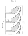
- FIG. 12 and FIG. 13 are views each illustrating a cross section corresponding to the A-A cross section in FIG. 2 where a part of a final turbine stage in a steam turbine 12 according to a third embodiment is illustrated.
- the configuration of the suction part 40 of the steam turbine 10 according to the first embodiment illustrated in FIG. 1 is exemplified to be described.
- FIG. 12 a rotational direction (arrow R) of the rotor blade and a flow direction (arrow F) of the steam are illustrated.
- guide grooves 100 guiding the water film to the suction port 51 are formed at the inner wall surface 23b of the diaphragm outer ring 23 in the steam turbine 12 according to the third embodiment.
- the guide groove 100 is continuously formed from, for example, an edge at an upstream side of the diaphragm outer ring 23 to the suction port 51.
- the guide grooves 100 may be formed in plural as illustrated in FIG. 12 and FIG. 13 . Note that the effect acquired by having the guide groove 100 can be showed by having at least one guide groove 100.
- the guide grooves 100 are formed, for example, in a direction in which the rotational direction of the rotor blade and the flow direction of the steam are combined as illustrated in FIG. 12 .
- the guide grooves 100 may be formed, for example, in the flow direction of the steam as illustrated in FIG. 13 .
- the direction where the guide grooves 100 are formed is not limited thereto, but it can be arbitrary set.
- the guide grooves 100 can be formed easily by, for example, the cutting such as the end milling.
- the guide grooves 100 are provided as stated above, and thereby, it is possible to precisely guide the water film adhered on the inner wall surface 23b of the diaphragm outer ring 23 to the suction port 51. It is thereby possible to effectively collect the water film adhered on the inner wall surface 23b of the diaphragm outer ring 23.
- the guide groove 100 is able to be applied to a steam turbine according to the other embodiments without being limited to the steam turbine 10 according to the first embodiment illustrated in FIG. 1 .
Landscapes
- Engineering & Computer Science (AREA)
- Mechanical Engineering (AREA)
- General Engineering & Computer Science (AREA)
- Chemical & Material Sciences (AREA)
- Materials Engineering (AREA)
- Turbine Rotor Nozzle Sealing (AREA)
Abstract
Description
- Embodiments described herein relate generally to a steam turbine.
- A steam turbine is used in power generation plants such as a nuclear power generation plant, a thermal power generation plant, a geothermal power generation plant. The steam turbine converts thermal energy of steam from high-pressure to low-pressure into a mechanical work. During this process, a temperature of the steam is lowered at a low-pressure part of the steam turbine, and a part of the steam condenses during an expansion work to increase wetness. The condensed moisture adheres or collides with a wall surface of a steam passage or a rotor blade of the steam turbine.
- There is a case when the moisture adhered on the wall surface of the steam passage or the rotor blade grows into waterdroplet whose particle diameter is large. The waterdroplet of large particle diameter moves toward a rotor blade at a subsequent stage (downstream) by a flow of the steam. The waterdroplet of large particle diameter collides with a front edge and so on of the rotor blade at the subsequent stage, and erodes the rotor blade. Besides, the waterdroplet of large particle diameter generates a resistance for a rotation of the rotor blade (so-called a moisture loss). Namely, existence of moisture in the steam passage deteriorates turbine efficiency and reliability of the steam turbine.
- Accordingly, in a conventional steam turbine, slits are provided at a stationary blade of a stationary component and a surface of a nozzle diaphragm outer ring of the stationary component supporting the stationary blade, and the moisture adhered on the surface of the stationary component of the steam passage is collected. The stationary component where the slits are provided has a hollow structure. The moisture collected by the slits pass through a hollow part, and is exhausted from the steam passage toward outside of the steam turbine.
- The slits at the stationary blade and the surface of the nozzle diaphragm outer ring at the conventional steam turbine are formed to have a width of, for example, 1 mm or less. Accordingly, the slit is generally formed by electric discharge machining. However, there is a case when it is difficult to process the slit by the electric discharge machining because the nozzle diaphragm and so on become thick according to large-sizing of the steam turbine.
-
-
FIG. 1 is a view illustrating a meridian cross section in a vertical direction of a steam turbine according to a first embodiment. -
FIG. 2 is a view illustrating a cross section of a part of a final turbine stage in the steam turbine according to the first embodiment. -
FIG. 3 is a view illustrating an A-A cross section inFIG. 2 where a part of the final turbine stage in the steam turbine according to the first embodiment is illustrated. -
FIG. 4 is a plan view illustrating a through hole formed at a diaphragm outer ring of the final turbine stage in the steam turbine according to the first embodiment. -
FIG. 5 is a view illustrating a cross section corresponding to the A-A cross section inFIG. 2 illustrating a configuration of another suction port in the steam turbine according to the first embodiment. -
FIG. 6 is a view illustrating a cross section corresponding to the A-A cross section inFIG. 2 illustrating a configuration of still another suction port in the steam turbine according to the first embodiment. -
FIG. 7 is a view illustrating a cross section of a part of a final turbine stage in a steam turbine according to a second embodiment. -
FIG. 8 is a view illustrating a B-B cross section inFIG. 7 illustrating a part of the final turbine stage in the steam turbine according to the second embodiment. -
FIG. 9 is a view illustrating the B-B cross section inFIG. 7 when a stationary blade having a solid blade structure is used for the stationary blade at the final turbine stage in the steam turbine according to the second embodiment. -
FIG. 10 is a view illustrating a cross section corresponding to the B-B cross section inFIG. 7 illustrating a configuration of another suction port in the steam turbine according to the second embodiment. -
FIG. 11 is a view illustrating the cross section corresponding to the B-B cross section inFIG. 7 illustrating a configuration of still another suction port in the steam turbine according to the second embodiment. -
FIG. 12 is a view illustrating a cross section corresponding to the A-A cross section inFIG. 2 where a part of a final turbine stage in a steam turbine according to a third embodiment is illustrated. -
FIG. 13 is a view illustrating a cross section corresponding to the A-A cross section inFIG. 2 where a part of the final turbine stage in the steam turbine according to the third embodiment is illustrated. - Hereinafter, embodiments of the present invention are described with reference to the drawings.
-
FIG. 1 is a view illustrating a meridian cross section in a vertical direction of asteam turbine 10 according to a first embodiment. As illustrated inFIG. 1 , thesteam turbine 10 includes acasing 20, and aturbine rotor 22 is provided to penetrate in thecasing 20.Plural rotor blades 21 are implanted into theturbine rotor 22 in a circumferential direction to make up a rotor blade cascade. The rotor blade cascades are provided in plural stages in a turbine rotor axial direction. Theturbine rotor 22 is rotatably supported by a not-illustrated rotor bearing. - A diaphragm
outer ring 23 is arranged at an inner side of thecasing 20. A diaphragminner ring 24 is arranged at an inner side of the diaphragmouter ring 23. Pluralstationary blades 25 are supported between the diaphragmouter ring 23 and the diaphragminner ring 24 in a circumferential direction to make up a stationary blade cascade. The stationary blade cascades are provided in plural stages to be arranged alternately with the rotor blade cascades in the turbine rotor axial direction. One turbine stage is made up of the stationary blade cascade and the rotor blade cascade positioning at an immediately downstream side of the stationary blade cascade. - A
gland sealing part 26 is provided between theturbine rotor 22 and thecasing 20 so as to prevent leakage of steam toward outside. Besides, a sealingpart 27 is provided between theturbine rotor 22 and the diaphragminner ring 24 so as to prevent leakage of steam. - A
steam inlet pipe 28 to introduce the steam toward inside is provided at thesteam turbine 10 while penetrating thecasing 20. Note that an exhaust flow passage is provided at a downstream side of a final turbine stage to exhaust the steam performing an expansion work at the turbine stage, though it is not illustrated. This exhaust flow passage is communicated with, for example, a condenser (not-illustrated). - Next, a configuration of the turbine stage to be low-pressure and where wet steam flows is described.
- Here, the final turbine stage is exemplified to be described as a turbine stage where the wet steam flows. Note that the turbine stage where the wet steam flows is not limited to the final turbine stage, and there is a case when turbine stages at an upstream side than the final turbine stage may be included. A function to secure generated waterdroplet and water film is included in the turbine stage where the wet steam flows.
-
FIG. 2 is a view illustrating a cross section of a part of the final turbine stage in thesteam turbine 10 according to the first embodiment. InFIG. 2 , a cross section between thestationary blades 25 is illustrated, and a suction side of thestationary blade 25 is seen.FIG. 3 is a view illustrating an A-A cross section inFIG. 2 in which a part of the final turbine stage in thesteam turbine 10 according to the first embodiment is illustrated.FIG. 4 is a plan view illustrating a throughhole 50 formed at the diaphragmouter ring 23 at the final turbine stage in thesteam turbine 10 according to the first embodiment. Note that a position (a position at an outside contour of the stationary blade 25) where an end part at an outer diameter side (diaphragmouter ring 23 side) of thestationary blade 25 is provided at an inner wall surface of the diaphragmouter ring 23 is represented by a dotted line. - As illustrated in
FIG. 2 , asuction part 40 collecting the waterdroplet or the water film is formed at a part making up the stationary blade cascade of the final turbine stage. A configuration of thesuction part 40 is described. Note that the steam flows from a left side to a right side inFIG. 2 . - The diaphragm
outer ring 23 has ahollow part 30 at inside thereof as illustrated inFIG. 2 . Thehollow part 30 is formed in, for example, an annular state in a circumferential direction. Thehollow part 30 is communicated with, for example, the condenser (not-illustrated) provided at outside of thesteam turbine 10. In this case, the waterdroplet and the water film collected from thesuction part 40 to thehollow part 30 are guided to the condenser. - A through
hole 50 communicating between asteam flow passage 29 where main steam flows and thehollow part 30 is formed at aninner wall 23a of the diaphragmouter ring 23. This throughhole 50 has, for example, a predetermined width W and is formed to be along a shape of the end part at the outer diameter side of thestationary blade 25 by which thesuction part 40 is made up as illustrated inFIG. 3 . Namely, the throughhole 50 is formed by a curved through hole having the width W. - The end part at the outer diameter side of the
stationary blade 25 is provided to cover a part of the throughhole 50 at aninner wall surface 23b of the diaphragmouter ring 23 as illustrated inFIG. 3 andFIG. 4 . As illustrated inFIG. 3 , a part which does not face the throughhole 50 of the end part of the stationary blade 25 (a part which does not cover the through hole 50) is joined to theinner wall surface 23b of the diaphragmouter ring 23 by welding. The welded part functions as ajoint part 60. Besides, the end part at the outer diameter side of thestationary blade 25 covering a part of the throughhole 50 is not welded to theinner wall surface 23b, and this part functions as anon-joint part 61. - As stated above, the
non-joint part 61 exists at a part of thejoint part 60, and is formed at a region where, for example, it is easy to collect the waterdroplet or the water film. Specifically, thenon-joint part 61 exists at a region from, for example, a front edge to a suction side of thestationary blade 25, a region from the front edge to a pressure side of thestationary blade 25, and so on. Note that an example in which thenon-joint part 61 is provided at the region from the front edge to the suction side of thestationary blade 25 is illustrated inFIG. 3 . - The part which is not covered with the
stationary blade 25 of the throughhole 50 at theinner wall surface 23b of the diaphragmouter ring 23 opens to thesteam flow passage 29. Namely, a part protruding toward outside of an outer edge of the end part of thestationary blade 25 of the throughhole 50 of theinner wall surface 23b opens to thesteam flow passage 29. This opening part functions as asuction port 51 sucking the waterdroplet and the water film flowing in thesteam flow passage 29. - An opening area of the
suction port 51 can be arbitrary changed by adjusting the width W of the throughhole 50 and an area in which thestationary blade 25 covers the throughhole 50. It is thereby possible to set the width W of the throughhole 50 to be wide compared to a width of a slit (for example, 1 mm or less) sucking the waterdroplet and the water film formed at an inner wall surface of a conventional diaphragm outer ring. It is not particularly limited, but the width W of the throughhole 50 can be formed to be approximately, for example, 2 mm to 20 mm. Accordingly, the throughhole 50 is easily formed not by the conventional electric discharge machining but by cutting and so on such as, for example, end milling. For example, it is possible to easily process the throughhole 50 even when a thickness of theinner wall 23a of the diaphragmouter ring 23 increases. - An end part at an inner diameter side (diaphragm
inner ring 24 side) of thestationary blade 25 is joined to an outer surface of the diaphragminner ring 24 by welding. Note that the end part at the inner diameter side of thestationary blade 25 may be fixed by the other methods without being limited to the welding. Besides, thestationary blade 25 may be integrally formed with the diaphragminner ring 24. - Note that, here, the
stationary blade 25 having the solid blade structure is exemplified to be described, but the configuration of the present embodiment can be applied to astationary blade 25 having either the solid or a hollow blade structure. Besides, for example, a low-pressure turbine can be cited as thesteam turbine 10. - Here, operations of the
steam turbine 10 are described with reference toFIG. 1 andFIG. 2 . - The steam flowing into the
steam turbine 10 via thesteam inlet pipe 28 passes through the expandingsteam flow passage 29 including thestationary blade 25, therotor blade 21 of each turbine stage while performing the expansion work, to rotate theturbine rotor 22. - A pressure and temperature of the steam are lowered as it goes downstream. For example, the pressure and temperature of the steam are lowered, and the waterdroplet is generated when, for example, wetness expands in nonequilibrium to approximately 3% to 5%. A particle diameter of the waterdroplet increases in accordance with the expansion of the steam at downstream.
- At this time, a part of the waterdroplet collides with surfaces of the
stationary blade 25 and therotor blade 21 and adheres thereto. For example, the waterdroplet collides with and adheres to therotor blade 21 of the turbine stage at an upstream side for one stage than the final turbine stage flows toward an outer peripheral side affected by a force such as a centrifugal force. Therefore, a lot of waterdroplet adheres to theinner wall surface 23b of the diaphragmouter ring 23 at the final turbine stage to form the water film. - The water film moves downstream affected by the flow of the steam while adhering on the
inner wall surface 23b, and is sucked from thesuction port 51. The sucked water film passes through the throughhole 50 and is collected into thehollow part 30. When thehollow part 30 is communicated with the condenser, the collected water film (water) is guided to the condenser. - Here, when the
hollow part 30 is communicated with the condenser (not-illustrated), pressures at thehollow part 30 and thesuction part 40 are lower than a pressure at thesteam flow passage 29. Accordingly, the water film is sucked from thesuction port 51. In addition to the water film, a part of flowing waterdroplet is sucked from thesuction port 51. - The steam passing through the final turbine stage passes through the exhaust flow passage (not-illustrated) provided at the downstream of the final turbine stage, and is guided to the condenser (not-illustrated).
- As stated above, it is possible to remove the water film and the waterdroplet generated at the
steam flow passage 29 of thesteam turbine 10 at an upstream side of therotor blade 21. It is thereby possible to reduce erosion and rotational resistance generated by the waterdroplet collided with therotor blade 21, and to suppress the deterioration of the turbine efficiency and the reliability. - As stated above, according to the
steam turbine 10 of the first embodiment, it is possible to easily form thesuction part 40 collecting the waterdroplet and the water film without depending on the electric discharge machining at the turbine stage where the water film and the waterdroplet are generated. For example, even when the thickness of components such as the diaphragmouter ring 23 increases caused by large-sizing of thesteam turbine 10, it is possible to easily form thesuction part 40 without depending on the electric discharge machining. - Here, the configuration of the
suction port 51 of thesuction part 40 is not limited to the above-stated configuration.FIG. 5 andFIG. 6 are views each illustrating a cross section corresponding to the A-A cross section inFIG. 2 illustrating a configuration of anothersuction port 51 at thesteam turbine 10 according to the first embodiment. - As illustrated in
FIG. 5 andFIG. 6 , thesuction port 51 may be made up of plural openings. InFIG. 5 , the end part at the outer diameter side of thestationary blade 25 is welded to theinner wall surface 23b of the diaphragmouter ring 23 so as to seal two portions of thesuction port 51 with a predetermined interval to formjoint parts 60. - In
FIG. 6 , the throughhole 50 is divided into plural, and non-through parts 52 are provided between the through holes 50. At the non-through part 52, the end part at the outer diameter side of thestationary blade 25 is welded to theinner wall surface 23b of the diaphragmouter ring 23, to form thejoint parts 60. It is also possible to easily form the throughholes 50 not by the electric discharge machining but by the cutting and so on even when the throughhole 50 is divided into plural. - The
suction port 51 is made up as stated above, and thereby, it is possible to increase joint strength between the end part at the outer diameter side of thestationary blade 25 and theinner wall surface 23b of the diaphragmouter ring 23. -
FIG. 7 is a view illustrating a cross section of a part of a final turbine stage in asteam turbine 11 according to a second embodiment. InFIG. 7 , a cross section between thestationary blades 25 is illustrated, and a suction side of thestationary blade 25 is seen.FIG. 8 is a view illustrating a B-B cross section inFIG. 7 where a part of the final turbine stage in thesteam turbine 11 according to the second embodiment is illustrated. Note that the same reference numerals are used for the same components as thesteam turbine 10 according to the first embodiment, and redundant description is not given or is simplified. - In the
steam turbine 11 according to the second embodiment, other than a configuration of thesuction part 40 is the same as the configuration of thesteam turbine 10 according to the first embodiment. Accordingly, here, the configuration of thesuction part 40 is mainly described. - As illustrated in
FIG. 7 , thesuction part 40 collecting the waterdroplet or the water film is formed at a part where the stationary blade cascade of the final turbine stage is formed. Note that the steam flows from a left side to a right side inFIG. 7 . - The diaphragm
outer ring 23 has thehollow part 30 at inside thereof as illustrated inFIG. 7 . Thehollow part 30 is communicated with, for example, the condenser (not-illustrated) provided at outside of thesteam turbine 11. - A through
hole 70 penetrating from theinner wall surface 23b to thehollow part 30 is formed at theinner wall 23a of the diaphragmouter ring 23. This throughhole 70 is formed at theinner wall 23a of the diaphragmouter ring 23 at a part where theinner wall surface 23b is covered with thestationary blade 25 when thestationary blade 25 is joined as illustrated inFIG. 8 . Namely, the throughhole 70 is formed at a part of theinner wall 23a facing thestationary blade 25. A cross-sectional shape of the throughhole 70 is not particularly limited, and for example, it is formed in circle as illustrated inFIG. 8 . - A recessed
groove 80 is formed at an end face at the outer diameter side of thestationary blade 25 as illustrated inFIG. 7 . This recessedgroove 80 makes up thesuction port 51 sucking the waterdroplet and the water film when the end part at the outer diameter side of thestationary blade 25 is welded to theinner wall surface 23b of the diaphragmouter ring 23. Namely, thesuction port 51 is formed at a part surrounded by an inner wall surface of the recessedgroove 80 and theinner wall surface 23b of the diaphragmouter ring 23. The recessedgroove 80 is formed at a region where it is easy to collect the waterdroplet or the water film such as, for example, a region from a front edge to a suction side of thestationary blade 25, and a region from the front edge to a pressure side of thestationary blade 25. - Here, a stationary blade having a
hollow part 90 at inside at the outer diameter side of thestationary blade 25 is exemplified as thestationary blade 25. Thishollow part 90 is communicated with thehollow part 30 via the throughhole 70. - The
stationary blade 25 is disposed to cover the throughhole 70 as illustrated inFIG. 8 , and a part other than the recessedgroove 80 of the end part of thestationary blade 25 is joined to theinner wall surface 23b of the diaphragmouter ring 23 by welding. The part where the welding is performed functions as thejoint part 60, and a part which is not welded and where the recessedgroove 80 is formed functions as thenon-joint part 61. - The
suction port 51 is communicated with thehollow part 30 via thehollow part 90 and the throughhole 70. An opening area of thesuction port 51 can be arbitrary changed by adjusting a groove depth and a groove width of the recessedgroove 80. The recessedgroove 80 is formed at the end face at the outer diameter side of thestationary blade 25, and therefore, it is easily formed by, for example, grinding, cutting, and so on. Besides, the recessedgroove 80 may be formed together with the stationary blade in itself at casting time of thestationary blade 25 without depending on the grinding, the cutting, and so on. It is possible to easily form the recessedgroove 80 by the formation methods of the recessedgroove 80 as stated above even when, for example, the thickness of thestationary blade 25 increases. - Also in the
steam turbine 11 according to the second embodiment, for example, the water film adhered to theinner wall surface 23b of the diaphragmouter ring 23 at the final turbine stage moves downward affected by the flow of the steam while being adhered to theinner wall surface 23b and is sucked from thesuction port 51 as same as thesteam turbine 10 according to the first embodiment. The sucked water film passes through the throughhole 70 and is colleted into thehollow par 30. When thehollow part 30 is communicated with the condenser (not-illustrated), the collected water film (water) is guided to the condenser. - As stated above, it is possible to remove the water film and the waterdroplet generated at the
steam flow passage 29 of thesteam turbine 11 at an upstream side of therotor blade 21. It is thereby possible to reduce the erosion and the rotational resistance generated by the waterdroplet colliding with therotor blade 21 and to suppress deterioration of the turbine efficiency and the reliability. - As stated above, according to the
steam turbine 11 of the second embodiment, it is possible to easily form thesuction part 40 collecting the waterdroplet and the water film at the turbine stage where the water film and the waterdroplet are generated. For example, it is possible to easily form thesuction part 40 even when the thickness of the component such as the diaphragmouter ring 23 increases caused by the large-sizing of thesteam turbine 11. - Note that, here, the
stationary blade 25 having the hollow blade structure is exemplified to be described, but the present embodiment can be applied to thestationary blade 25 having the solid blade structure. -
FIG. 9 is a view illustrating the B-B cross section inFIG. 7 when the stationary blade having the solid blade structure is used for thestationary blade 25 at the final turbine stage in thesteam turbine 11 according to the second embodiment. - In this case, the through
hole 70 is formed at a position communicating with the recessedgroove 80 formed at the end face at the outer diameter side of thestationary blade 25 as illustrated inFIG. 9 . In other words, the recessedgroove 80 is formed at the end face at the outer diameter side of thestationary blade 25 up to the position communicating with the throughhole 70. Thesuction port 51 is communicated with thehollow part 30 via the recessedgroove 80 and the throughhole 70. - Besides, a configuration of the
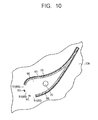
suction port 51 of thesuction part 40 is not limited to the above-stated configuration.FIG. 10 andFIG. 11 are views each illustrating a cross section corresponding to the B-B cross section inFIG. 7 illustrating the configuration of anothersuction port 51 in thesteam turbine 11 according to the second embodiment. Note that, here, thestationary blade 25 having the hollow blade structure is exemplified to be described. - As illustrated in
FIG. 10 andFIG. 11 , thesuction port 51 may be made up by plural openings. InFIG. 10 , thejoint parts 60 are formed by welding between a bottom part of the recessedgroove 80 and theinner wall surface 23b of the diaphragmouter ring 23 so that two portions of thesuction port 51 are sealed with a predetermined interval. - In
FIG. 11 , the recessedgroove 80 is divided into plural, andnon-groove parts 81 where the recessedgrooves 80 are not formed are provided between the recessedgrooves 80. At each of thenon-groove parts 81, the end part at the outer diameter side of thestationary blade 25 is welded to theinner wall surface 23b of the diaphragmouter ring 23 to form thejoint part 60. It is possible to easily form the divided recessedgrooves 80 by a method similar to the above-stated method forming the recessedgroove 80 even in a case when the recessedgroove 80 is divided into plural. - The
suction port 51 is made up as stated above, and thereby, it is possible to increase the joint strength between the end part at the outer diameter side of thestationary blade 25 and theinner wall surface 23b of the diaphragmouter ring 23. -
FIG. 12 andFIG. 13 are views each illustrating a cross section corresponding to the A-A cross section inFIG. 2 where a part of a final turbine stage in a steam turbine 12 according to a third embodiment is illustrated. Here, the configuration of thesuction part 40 of thesteam turbine 10 according to the first embodiment illustrated inFIG. 1 is exemplified to be described. InFIG. 12 , a rotational direction (arrow R) of the rotor blade and a flow direction (arrow F) of the steam are illustrated. - As illustrated in
FIG. 12 andFIG. 13 , guidegrooves 100 guiding the water film to thesuction port 51 are formed at theinner wall surface 23b of the diaphragmouter ring 23 in the steam turbine 12 according to the third embodiment. Theguide groove 100 is continuously formed from, for example, an edge at an upstream side of the diaphragmouter ring 23 to thesuction port 51. Theguide grooves 100 may be formed in plural as illustrated inFIG. 12 andFIG. 13 . Note that the effect acquired by having theguide groove 100 can be showed by having at least oneguide groove 100. - The
guide grooves 100 are formed, for example, in a direction in which the rotational direction of the rotor blade and the flow direction of the steam are combined as illustrated inFIG. 12 . In addition, theguide grooves 100 may be formed, for example, in the flow direction of the steam as illustrated inFIG. 13 . Note that the direction where theguide grooves 100 are formed is not limited thereto, but it can be arbitrary set. Theguide grooves 100 can be formed easily by, for example, the cutting such as the end milling. - The
guide grooves 100 are provided as stated above, and thereby, it is possible to precisely guide the water film adhered on theinner wall surface 23b of the diaphragmouter ring 23 to thesuction port 51. It is thereby possible to effectively collect the water film adhered on theinner wall surface 23b of the diaphragmouter ring 23. - Here, the
guide groove 100 is able to be applied to a steam turbine according to the other embodiments without being limited to thesteam turbine 10 according to the first embodiment illustrated inFIG. 1 . - According to the above-described embodiments, it is possible to easily form the suction part collecting the waterdroplet and the water film generated in the turbine even in a case when the thickness of the component increases.
- While certain embodiments have been described, these embodiments have been presented by way of example only, and are not intended to limit the scope of the inventions. Indeed, the novel embodiments described herein may be embodied in a variety of other forms; furthermore, various omissions, substitutions and changes in the form of the embodiments described herein may be made without departing from the spirit of the inventions. The accompanying claims and their equivalents are intended to cover such forms or modifications as would fall within the scope and spirit of the inventions.
Claims (6)
- A steam turbine, comprising:a casing where a turbine rotor in which rotor blades are implanted is provided to penetrate;a diaphragm outer ring arranged at an inner side of the casing, and having a hollow part inside thereof;a diaphragm inner ring arranged at an inner side of the diaphragm outer ring;a stationary blade forming a turbine stage with the rotor blade, at least whose end part at an outer diameter side is joined to the diaphragm outer ring by welding, and supported between the diaphragm outer ring and the diaphragm inner ring;a non-joint part existing at a part of a joint part between the diaphragm outer ring and the stationary blade at the turbine stage where wet steam flows, and in which the end part at the outer diameter side of the stationary blade is not welded to the diaphragm outer ring; anda suction part communicated with the hollow part, and collecting waterdroplet or a water film from the non-joint part.
- The steam turbine according to claim 1,
wherein the suction part includes:a through hole formed at an inner wall of the diaphragm outer ring, and communicating between a steam flow passage where main steam flows and the hollow part; anda suction port made up by the through hole which is not covered with the stationary blade when the stationary blade is joined to cover a part of the through hole at an inner wall surface of the diaphragm outer ring,wherein the non-joint part is the end part at the outer diameter side of the stationary blade covering a part of the through hole. - The steam turbine according to claim 1,
wherein the suction part includes:a through hole formed at an inner wall of a part where an inner wall surface is covered with the stationary blade when the stationary blade is joined, and communicated with the hollow part; anda suction port formed at an end face at the outer diameter side of the stationary blade and made up by a recessed groove communicated with the through hole,wherein the non-joint part is the end part at the outer diameter side of the stationary blade where the recessed groove is formed. - The steam turbine according to either of claims 2 or 3,
wherein the suction port is made up of one or plural opening(s). - The steam turbine according to any of claims 2 to 4,
wherein a guide groove guiding the water film to the suction port is formed at the inner wall surface of the diaphragm outer ring. - The steam turbine according to any preceding claim,
wherein the hollow part is communicated with a condenser provided at outside of the steam turbine.
Applications Claiming Priority (1)
| Application Number | Priority Date | Filing Date | Title |
|---|---|---|---|
| JP2013049321A JP6000876B2 (en) | 2013-03-12 | 2013-03-12 | Steam turbine |
Publications (2)
| Publication Number | Publication Date |
|---|---|
| EP2778348A1 true EP2778348A1 (en) | 2014-09-17 |
| EP2778348B1 EP2778348B1 (en) | 2018-11-28 |
Family
ID=50289401
Family Applications (1)
| Application Number | Title | Priority Date | Filing Date |
|---|---|---|---|
| EP14159221.2A Active EP2778348B1 (en) | 2013-03-12 | 2014-03-12 | Steam turbine |
Country Status (3)
| Country | Link |
|---|---|
| US (1) | US9945238B2 (en) |
| EP (1) | EP2778348B1 (en) |
| JP (1) | JP6000876B2 (en) |
Families Citing this family (2)
| Publication number | Priority date | Publication date | Assignee | Title |
|---|---|---|---|---|
| ITCO20130051A1 (en) * | 2013-10-23 | 2015-04-24 | Nuovo Pignone Srl | METHOD FOR THE PRODUCTION OF A STAGE OF A STEAM TURBINE |
| US20190264616A1 (en) * | 2018-02-28 | 2019-08-29 | United Technologies Corporation | Dirt collector for gas turbine engine |
Citations (4)
| Publication number | Priority date | Publication date | Assignee | Title |
|---|---|---|---|---|
| JPH0861006A (en) * | 1994-08-24 | 1996-03-05 | Hitachi Ltd | Steam turbine |
| EP0726384A1 (en) * | 1995-02-13 | 1996-08-14 | Abb Research Ltd. | Stator blade for steam turbines |
| EP1744018A1 (en) * | 2005-07-15 | 2007-01-17 | Kabushiki Kaisha Toshiba | Steam turbine nozzle vane, nozzle rings and method of fabricating the vane |
| US20100329853A1 (en) * | 2009-06-30 | 2010-12-30 | General Electric Company | Moisture removal provisions for steam turbine |
Family Cites Families (8)
| Publication number | Priority date | Publication date | Assignee | Title |
|---|---|---|---|---|
| GB307762A (en) * | 1928-03-12 | 1929-12-12 | Bbc Brown Boveri & Cie | Improvements in and relating to steam turbines |
| US1935451A (en) * | 1932-08-29 | 1933-11-14 | Jones William Anthony | Multiple stage steam turbine |
| JPS5518485Y2 (en) * | 1977-01-25 | 1980-04-30 | ||
| JP3093479B2 (en) * | 1992-10-07 | 2000-10-03 | 株式会社東芝 | Steam turbine moisture separator |
| JPH0925803A (en) * | 1995-05-11 | 1997-01-28 | Mitsubishi Heavy Ind Ltd | Drain removal device for steam turbine |
| JPH10331604A (en) * | 1997-05-30 | 1998-12-15 | Toshiba Corp | Steam turbine plant |
| JP2004124751A (en) * | 2002-09-30 | 2004-04-22 | Toshiba Corp | Steam turbine moisture separator |
| US7789618B2 (en) * | 2006-08-28 | 2010-09-07 | General Electric Company | Systems for moisture removal in steam turbine engines |
-
2013
- 2013-03-12 JP JP2013049321A patent/JP6000876B2/en not_active Expired - Fee Related
-
2014
- 2014-02-25 US US14/188,828 patent/US9945238B2/en active Active
- 2014-03-12 EP EP14159221.2A patent/EP2778348B1/en active Active
Patent Citations (4)
| Publication number | Priority date | Publication date | Assignee | Title |
|---|---|---|---|---|
| JPH0861006A (en) * | 1994-08-24 | 1996-03-05 | Hitachi Ltd | Steam turbine |
| EP0726384A1 (en) * | 1995-02-13 | 1996-08-14 | Abb Research Ltd. | Stator blade for steam turbines |
| EP1744018A1 (en) * | 2005-07-15 | 2007-01-17 | Kabushiki Kaisha Toshiba | Steam turbine nozzle vane, nozzle rings and method of fabricating the vane |
| US20100329853A1 (en) * | 2009-06-30 | 2010-12-30 | General Electric Company | Moisture removal provisions for steam turbine |
Also Published As
| Publication number | Publication date |
|---|---|
| EP2778348B1 (en) | 2018-11-28 |
| JP2014173568A (en) | 2014-09-22 |
| US9945238B2 (en) | 2018-04-17 |
| US20140271140A1 (en) | 2014-09-18 |
| JP6000876B2 (en) | 2016-10-05 |
Similar Documents
| Publication | Publication Date | Title |
|---|---|---|
| CN101403321B (en) | Axial flow turbine and stage structure thereof | |
| US8727713B2 (en) | Rotor oscillation preventing structure and steam turbine using the same | |
| EP2612993B1 (en) | Slotted turbine airfoil | |
| US11333029B2 (en) | Method for manufacturing a stage of a steam turbine | |
| US9850781B2 (en) | Steam turbine | |
| CN107208493B (en) | turbine | |
| CN110945212B (en) | Steam turbine blade, steam turbine, and method for manufacturing steam turbine blade | |
| JP2016113966A (en) | Steam turbine stationary blade | |
| EP3064709B1 (en) | Turbine bucket platform for influencing hot gas incursion losses | |
| JP2019035384A (en) | Steam turbine | |
| US9945238B2 (en) | Steam turbine | |
| JP2016166569A (en) | Steam turbine | |
| JP2013124561A (en) | Steam turbine | |
| WO2018181331A1 (en) | Drain removing device and steam turbine | |
| KR102256876B1 (en) | Axially faced seal system | |
| JP6833598B2 (en) | Nozzle diaphragm, steam turbine | |
| JP6228440B2 (en) | Turbomachine nozzle with fluid conduit and associated turbomachine | |
| JP2019035347A (en) | Turbine component, turbine blade, axial flow turbine and remodeling method thereof, and manufacturing method of turbine blade | |
| US9644483B2 (en) | Turbomachine bucket having flow interrupter and related turbomachine | |
| US20140037439A1 (en) | Turbomachine exhaust diffuser | |
| CN111622811A (en) | Axial flow turbine | |
| JP5766528B2 (en) | Steam turbine stationary blade and method of assembling the same | |
| JP2007138864A (en) | Steam turbine stage and steam turbine | |
| JP2017053287A (en) | Steam turbine |
Legal Events
| Date | Code | Title | Description |
|---|---|---|---|
| 17P | Request for examination filed |
Effective date: 20140312 |
|
| AK | Designated contracting states |
Kind code of ref document: A1 Designated state(s): AL AT BE BG CH CY CZ DE DK EE ES FI FR GB GR HR HU IE IS IT LI LT LU LV MC MK MT NL NO PL PT RO RS SE SI SK SM TR |
|
| AX | Request for extension of the european patent |
Extension state: BA ME |
|
| PUAI | Public reference made under article 153(3) epc to a published international application that has entered the european phase |
Free format text: ORIGINAL CODE: 0009012 |
|
| GRAP | Despatch of communication of intention to grant a patent |
Free format text: ORIGINAL CODE: EPIDOSNIGR1 |
|
| STAA | Information on the status of an ep patent application or granted ep patent |
Free format text: STATUS: GRANT OF PATENT IS INTENDED |
|
| INTG | Intention to grant announced |
Effective date: 20180605 |
|
| RIN1 | Information on inventor provided before grant (corrected) |
Inventor name: OHASHI, SHINICHIRO Inventor name: HASHIDATE, TADAYUKI Inventor name: TOMINAGA, JUNICHI |
|
| GRAJ | Information related to disapproval of communication of intention to grant by the applicant or resumption of examination proceedings by the epo deleted |
Free format text: ORIGINAL CODE: EPIDOSDIGR1 |
|
| STAA | Information on the status of an ep patent application or granted ep patent |
Free format text: STATUS: REQUEST FOR EXAMINATION WAS MADE |
|
| GRAR | Information related to intention to grant a patent recorded |
Free format text: ORIGINAL CODE: EPIDOSNIGR71 |
|
| GRAS | Grant fee paid |
Free format text: ORIGINAL CODE: EPIDOSNIGR3 |
|
| STAA | Information on the status of an ep patent application or granted ep patent |
Free format text: STATUS: GRANT OF PATENT IS INTENDED |
|
| GRAA | (expected) grant |
Free format text: ORIGINAL CODE: 0009210 |
|
| STAA | Information on the status of an ep patent application or granted ep patent |
Free format text: STATUS: THE PATENT HAS BEEN GRANTED |
|
| INTC | Intention to grant announced (deleted) | ||
| INTG | Intention to grant announced |
Effective date: 20181018 |
|
| AK | Designated contracting states |
Kind code of ref document: B1 Designated state(s): AL AT BE BG CH CY CZ DE DK EE ES FI FR GB GR HR HU IE IS IT LI LT LU LV MC MK MT NL NO PL PT RO RS SE SI SK SM TR |
|
| REG | Reference to a national code |
Ref country code: CH Ref legal event code: EP |
|
| REG | Reference to a national code |
Ref country code: AT Ref legal event code: REF Ref document number: 1070480 Country of ref document: AT Kind code of ref document: T Effective date: 20181215 |
|
| REG | Reference to a national code |
Ref country code: DE Ref legal event code: R096 Ref document number: 602014036789 Country of ref document: DE |
|
| REG | Reference to a national code |
Ref country code: IE Ref legal event code: FG4D |
|
| REG | Reference to a national code |
Ref country code: CH Ref legal event code: NV Representative=s name: SERVOPATENT GMBH, CH |
|
| REG | Reference to a national code |
Ref country code: NL Ref legal event code: MP Effective date: 20181128 |
|
| REG | Reference to a national code |
Ref country code: LT Ref legal event code: MG4D |
|
| REG | Reference to a national code |
Ref country code: AT Ref legal event code: MK05 Ref document number: 1070480 Country of ref document: AT Kind code of ref document: T Effective date: 20181128 |
|
| PG25 | Lapsed in a contracting state [announced via postgrant information from national office to epo] |
Ref country code: ES Free format text: LAPSE BECAUSE OF FAILURE TO SUBMIT A TRANSLATION OF THE DESCRIPTION OR TO PAY THE FEE WITHIN THE PRESCRIBED TIME-LIMIT Effective date: 20181128 Ref country code: LV Free format text: LAPSE BECAUSE OF FAILURE TO SUBMIT A TRANSLATION OF THE DESCRIPTION OR TO PAY THE FEE WITHIN THE PRESCRIBED TIME-LIMIT Effective date: 20181128 Ref country code: AT Free format text: LAPSE BECAUSE OF FAILURE TO SUBMIT A TRANSLATION OF THE DESCRIPTION OR TO PAY THE FEE WITHIN THE PRESCRIBED TIME-LIMIT Effective date: 20181128 Ref country code: HR Free format text: LAPSE BECAUSE OF FAILURE TO SUBMIT A TRANSLATION OF THE DESCRIPTION OR TO PAY THE FEE WITHIN THE PRESCRIBED TIME-LIMIT Effective date: 20181128 Ref country code: IS Free format text: LAPSE BECAUSE OF FAILURE TO SUBMIT A TRANSLATION OF THE DESCRIPTION OR TO PAY THE FEE WITHIN THE PRESCRIBED TIME-LIMIT Effective date: 20190328 Ref country code: FI Free format text: LAPSE BECAUSE OF FAILURE TO SUBMIT A TRANSLATION OF THE DESCRIPTION OR TO PAY THE FEE WITHIN THE PRESCRIBED TIME-LIMIT Effective date: 20181128 Ref country code: BG Free format text: LAPSE BECAUSE OF FAILURE TO SUBMIT A TRANSLATION OF THE DESCRIPTION OR TO PAY THE FEE WITHIN THE PRESCRIBED TIME-LIMIT Effective date: 20190228 Ref country code: LT Free format text: LAPSE BECAUSE OF FAILURE TO SUBMIT A TRANSLATION OF THE DESCRIPTION OR TO PAY THE FEE WITHIN THE PRESCRIBED TIME-LIMIT Effective date: 20181128 Ref country code: NO Free format text: LAPSE BECAUSE OF FAILURE TO SUBMIT A TRANSLATION OF THE DESCRIPTION OR TO PAY THE FEE WITHIN THE PRESCRIBED TIME-LIMIT Effective date: 20190228 |
|
| PG25 | Lapsed in a contracting state [announced via postgrant information from national office to epo] |
Ref country code: RS Free format text: LAPSE BECAUSE OF FAILURE TO SUBMIT A TRANSLATION OF THE DESCRIPTION OR TO PAY THE FEE WITHIN THE PRESCRIBED TIME-LIMIT Effective date: 20181128 Ref country code: PT Free format text: LAPSE BECAUSE OF FAILURE TO SUBMIT A TRANSLATION OF THE DESCRIPTION OR TO PAY THE FEE WITHIN THE PRESCRIBED TIME-LIMIT Effective date: 20190328 Ref country code: GR Free format text: LAPSE BECAUSE OF FAILURE TO SUBMIT A TRANSLATION OF THE DESCRIPTION OR TO PAY THE FEE WITHIN THE PRESCRIBED TIME-LIMIT Effective date: 20190301 Ref country code: SE Free format text: LAPSE BECAUSE OF FAILURE TO SUBMIT A TRANSLATION OF THE DESCRIPTION OR TO PAY THE FEE WITHIN THE PRESCRIBED TIME-LIMIT Effective date: 20181128 Ref country code: AL Free format text: LAPSE BECAUSE OF FAILURE TO SUBMIT A TRANSLATION OF THE DESCRIPTION OR TO PAY THE FEE WITHIN THE PRESCRIBED TIME-LIMIT Effective date: 20181128 |
|
| PG25 | Lapsed in a contracting state [announced via postgrant information from national office to epo] |
Ref country code: NL Free format text: LAPSE BECAUSE OF FAILURE TO SUBMIT A TRANSLATION OF THE DESCRIPTION OR TO PAY THE FEE WITHIN THE PRESCRIBED TIME-LIMIT Effective date: 20181128 |
|
| PG25 | Lapsed in a contracting state [announced via postgrant information from national office to epo] |
Ref country code: DK Free format text: LAPSE BECAUSE OF FAILURE TO SUBMIT A TRANSLATION OF THE DESCRIPTION OR TO PAY THE FEE WITHIN THE PRESCRIBED TIME-LIMIT Effective date: 20181128 Ref country code: PL Free format text: LAPSE BECAUSE OF FAILURE TO SUBMIT A TRANSLATION OF THE DESCRIPTION OR TO PAY THE FEE WITHIN THE PRESCRIBED TIME-LIMIT Effective date: 20181128 Ref country code: CZ Free format text: LAPSE BECAUSE OF FAILURE TO SUBMIT A TRANSLATION OF THE DESCRIPTION OR TO PAY THE FEE WITHIN THE PRESCRIBED TIME-LIMIT Effective date: 20181128 Ref country code: IT Free format text: LAPSE BECAUSE OF FAILURE TO SUBMIT A TRANSLATION OF THE DESCRIPTION OR TO PAY THE FEE WITHIN THE PRESCRIBED TIME-LIMIT Effective date: 20181128 |
|
| REG | Reference to a national code |
Ref country code: DE Ref legal event code: R097 Ref document number: 602014036789 Country of ref document: DE |
|
| PG25 | Lapsed in a contracting state [announced via postgrant information from national office to epo] |
Ref country code: RO Free format text: LAPSE BECAUSE OF FAILURE TO SUBMIT A TRANSLATION OF THE DESCRIPTION OR TO PAY THE FEE WITHIN THE PRESCRIBED TIME-LIMIT Effective date: 20181128 Ref country code: SK Free format text: LAPSE BECAUSE OF FAILURE TO SUBMIT A TRANSLATION OF THE DESCRIPTION OR TO PAY THE FEE WITHIN THE PRESCRIBED TIME-LIMIT Effective date: 20181128 Ref country code: SM Free format text: LAPSE BECAUSE OF FAILURE TO SUBMIT A TRANSLATION OF THE DESCRIPTION OR TO PAY THE FEE WITHIN THE PRESCRIBED TIME-LIMIT Effective date: 20181128 Ref country code: EE Free format text: LAPSE BECAUSE OF FAILURE TO SUBMIT A TRANSLATION OF THE DESCRIPTION OR TO PAY THE FEE WITHIN THE PRESCRIBED TIME-LIMIT Effective date: 20181128 |
|
| PLBE | No opposition filed within time limit |
Free format text: ORIGINAL CODE: 0009261 |
|
| STAA | Information on the status of an ep patent application or granted ep patent |
Free format text: STATUS: NO OPPOSITION FILED WITHIN TIME LIMIT |
|
| PG25 | Lapsed in a contracting state [announced via postgrant information from national office to epo] |
Ref country code: SI Free format text: LAPSE BECAUSE OF FAILURE TO SUBMIT A TRANSLATION OF THE DESCRIPTION OR TO PAY THE FEE WITHIN THE PRESCRIBED TIME-LIMIT Effective date: 20181128 Ref country code: MC Free format text: LAPSE BECAUSE OF FAILURE TO SUBMIT A TRANSLATION OF THE DESCRIPTION OR TO PAY THE FEE WITHIN THE PRESCRIBED TIME-LIMIT Effective date: 20181128 |
|
| 26N | No opposition filed |
Effective date: 20190829 |
|
| GBPC | Gb: european patent ceased through non-payment of renewal fee |
Effective date: 20190312 |
|
| PG25 | Lapsed in a contracting state [announced via postgrant information from national office to epo] |
Ref country code: LU Free format text: LAPSE BECAUSE OF NON-PAYMENT OF DUE FEES Effective date: 20190312 |
|
| REG | Reference to a national code |
Ref country code: BE Ref legal event code: MM Effective date: 20190331 |
|
| PG25 | Lapsed in a contracting state [announced via postgrant information from national office to epo] |
Ref country code: GB Free format text: LAPSE BECAUSE OF NON-PAYMENT OF DUE FEES Effective date: 20190312 Ref country code: IE Free format text: LAPSE BECAUSE OF NON-PAYMENT OF DUE FEES Effective date: 20190312 |
|
| PG25 | Lapsed in a contracting state [announced via postgrant information from national office to epo] |
Ref country code: BE Free format text: LAPSE BECAUSE OF NON-PAYMENT OF DUE FEES Effective date: 20190331 Ref country code: FR Free format text: LAPSE BECAUSE OF NON-PAYMENT OF DUE FEES Effective date: 20190331 |
|
| PG25 | Lapsed in a contracting state [announced via postgrant information from national office to epo] |
Ref country code: TR Free format text: LAPSE BECAUSE OF FAILURE TO SUBMIT A TRANSLATION OF THE DESCRIPTION OR TO PAY THE FEE WITHIN THE PRESCRIBED TIME-LIMIT Effective date: 20181128 |
|
| REG | Reference to a national code |
Ref country code: CH Ref legal event code: PCAR Free format text: NEW ADDRESS: WANNERSTRASSE 9/1, 8045 ZUERICH (CH) |
|
| PG25 | Lapsed in a contracting state [announced via postgrant information from national office to epo] |
Ref country code: MT Free format text: LAPSE BECAUSE OF NON-PAYMENT OF DUE FEES Effective date: 20190312 |
|
| PG25 | Lapsed in a contracting state [announced via postgrant information from national office to epo] |
Ref country code: CY Free format text: LAPSE BECAUSE OF FAILURE TO SUBMIT A TRANSLATION OF THE DESCRIPTION OR TO PAY THE FEE WITHIN THE PRESCRIBED TIME-LIMIT Effective date: 20181128 |
|
| PG25 | Lapsed in a contracting state [announced via postgrant information from national office to epo] |
Ref country code: HU Free format text: LAPSE BECAUSE OF FAILURE TO SUBMIT A TRANSLATION OF THE DESCRIPTION OR TO PAY THE FEE WITHIN THE PRESCRIBED TIME-LIMIT; INVALID AB INITIO Effective date: 20140312 |
|
| PG25 | Lapsed in a contracting state [announced via postgrant information from national office to epo] |
Ref country code: MK Free format text: LAPSE BECAUSE OF FAILURE TO SUBMIT A TRANSLATION OF THE DESCRIPTION OR TO PAY THE FEE WITHIN THE PRESCRIBED TIME-LIMIT Effective date: 20181128 |
|
| PGFP | Annual fee paid to national office [announced via postgrant information from national office to epo] |
Ref country code: CH Payment date: 20230401 Year of fee payment: 10 |
|
| PGFP | Annual fee paid to national office [announced via postgrant information from national office to epo] |
Ref country code: DE Payment date: 20231229 Year of fee payment: 11 |
|
| REG | Reference to a national code |
Ref country code: CH Ref legal event code: PL |
|
| PG25 | Lapsed in a contracting state [announced via postgrant information from national office to epo] |
Ref country code: CH Free format text: LAPSE BECAUSE OF NON-PAYMENT OF DUE FEES Effective date: 20240331 |
|
| REG | Reference to a national code |
Ref country code: DE Ref legal event code: R119 Ref document number: 602014036789 Country of ref document: DE |
|
| PG25 | Lapsed in a contracting state [announced via postgrant information from national office to epo] |
Ref country code: DE Free format text: LAPSE BECAUSE OF NON-PAYMENT OF DUE FEES Effective date: 20251001 |