EP2778346A1 - Rotors for a gas turbine engine, corresponding gas turbine engine and method - Google Patents
Rotors for a gas turbine engine, corresponding gas turbine engine and method Download PDFInfo
- Publication number
- EP2778346A1 EP2778346A1 EP14159988.6A EP14159988A EP2778346A1 EP 2778346 A1 EP2778346 A1 EP 2778346A1 EP 14159988 A EP14159988 A EP 14159988A EP 2778346 A1 EP2778346 A1 EP 2778346A1
- Authority
- EP
- European Patent Office
- Prior art keywords
- tip
- rotor
- suction side
- edge
- radius
- Prior art date
- Legal status (The legal status is an assumption and is not a legal conclusion. Google has not performed a legal analysis and makes no representation as to the accuracy of the status listed.)
- Granted
Links
Images



Classifications
-
- F—MECHANICAL ENGINEERING; LIGHTING; HEATING; WEAPONS; BLASTING
- F02—COMBUSTION ENGINES; HOT-GAS OR COMBUSTION-PRODUCT ENGINE PLANTS
- F02C—GAS-TURBINE PLANTS; AIR INTAKES FOR JET-PROPULSION PLANTS; CONTROLLING FUEL SUPPLY IN AIR-BREATHING JET-PROPULSION PLANTS
- F02C7/00—Features, components parts, details or accessories, not provided for in, or of interest apart form groups F02C1/00 - F02C6/00; Air intakes for jet-propulsion plants
- F02C7/28—Arrangement of seals
-
- F—MECHANICAL ENGINEERING; LIGHTING; HEATING; WEAPONS; BLASTING
- F01—MACHINES OR ENGINES IN GENERAL; ENGINE PLANTS IN GENERAL; STEAM ENGINES
- F01D—NON-POSITIVE DISPLACEMENT MACHINES OR ENGINES, e.g. STEAM TURBINES
- F01D11/00—Preventing or minimising internal leakage of working-fluid, e.g. between stages
- F01D11/08—Preventing or minimising internal leakage of working-fluid, e.g. between stages for sealing space between rotor blade tips and stator
-
- F—MECHANICAL ENGINEERING; LIGHTING; HEATING; WEAPONS; BLASTING
- F01—MACHINES OR ENGINES IN GENERAL; ENGINE PLANTS IN GENERAL; STEAM ENGINES
- F01D—NON-POSITIVE DISPLACEMENT MACHINES OR ENGINES, e.g. STEAM TURBINES
- F01D5/00—Blades; Blade-carrying members; Heating, heat-insulating, cooling or antivibration means on the blades or the members
- F01D5/12—Blades
- F01D5/14—Form or construction
-
- F—MECHANICAL ENGINEERING; LIGHTING; HEATING; WEAPONS; BLASTING
- F01—MACHINES OR ENGINES IN GENERAL; ENGINE PLANTS IN GENERAL; STEAM ENGINES
- F01D—NON-POSITIVE DISPLACEMENT MACHINES OR ENGINES, e.g. STEAM TURBINES
- F01D5/00—Blades; Blade-carrying members; Heating, heat-insulating, cooling or antivibration means on the blades or the members
- F01D5/12—Blades
- F01D5/14—Form or construction
- F01D5/20—Specially-shaped blade tips to seal space between tips and stator
-
- F—MECHANICAL ENGINEERING; LIGHTING; HEATING; WEAPONS; BLASTING
- F01—MACHINES OR ENGINES IN GENERAL; ENGINE PLANTS IN GENERAL; STEAM ENGINES
- F01D—NON-POSITIVE DISPLACEMENT MACHINES OR ENGINES, e.g. STEAM TURBINES
- F01D5/00—Blades; Blade-carrying members; Heating, heat-insulating, cooling or antivibration means on the blades or the members
- F01D5/12—Blades
- F01D5/22—Blade-to-blade connections, e.g. for damping vibrations
- F01D5/225—Blade-to-blade connections, e.g. for damping vibrations by shrouding
-
- F—MECHANICAL ENGINEERING; LIGHTING; HEATING; WEAPONS; BLASTING
- F05—INDEXING SCHEMES RELATING TO ENGINES OR PUMPS IN VARIOUS SUBCLASSES OF CLASSES F01-F04
- F05D—INDEXING SCHEME FOR ASPECTS RELATING TO NON-POSITIVE-DISPLACEMENT MACHINES OR ENGINES, GAS-TURBINES OR JET-PROPULSION PLANTS
- F05D2250/00—Geometry
- F05D2250/10—Two-dimensional
- F05D2250/19—Two-dimensional machined; miscellaneous
- F05D2250/192—Two-dimensional machined; miscellaneous bevelled
-
- Y—GENERAL TAGGING OF NEW TECHNOLOGICAL DEVELOPMENTS; GENERAL TAGGING OF CROSS-SECTIONAL TECHNOLOGIES SPANNING OVER SEVERAL SECTIONS OF THE IPC; TECHNICAL SUBJECTS COVERED BY FORMER USPC CROSS-REFERENCE ART COLLECTIONS [XRACs] AND DIGESTS
- Y02—TECHNOLOGIES OR APPLICATIONS FOR MITIGATION OR ADAPTATION AGAINST CLIMATE CHANGE
- Y02T—CLIMATE CHANGE MITIGATION TECHNOLOGIES RELATED TO TRANSPORTATION
- Y02T50/00—Aeronautics or air transport
- Y02T50/60—Efficient propulsion technologies, e.g. for aircraft
Definitions
- the application relates generally to gas turbine engines, and more particularly to rotor blades for a gas turbine engine.
- Compressors and turbines of gas turbine engines comprise rotating turbo-machinery having a plurality of rotor blades, including for example axial compressors, centrifugal compressors (i.e. impellers) and turbines.
- a major source of inefficiency of such compressors and/or turbines is caused by tip leakage flow, whereby air escapes through the radial tip clearance gap formed between the tips of the rotor blades and the surrounding casing or shroud.
- a rotor for a gas turbine engine comprising: a hub defining a central axis of rotation about which the rotor is rotatable and a plurality of blades radially extending from the hub, the blades being adapted to project into an annular gas flow passage of said gas turbine engine, each of said blades having a remote blade tip defining an outer tip surface, and a leading edge defined between opposed pressure and suction side airfoil surfaces; a shroud circumferentially surrounding the rotor and having a radially inner surface adjacent to the blade tips, a radial distance between the inner surface of the shroud and the outer tip surface of the blades defining a radial tip clearance gap therebetween; and the tip of each of the blades having a pressure side edge formed at a first intersection between the outer tip surface and the pressure side airfoil surface, and a suction side edge formed at a second intersection between the outer tip surface and the suction side airfoil surface, the pressure side edge having a first
- a rotor for a gas turbine engine comprising: a hub defining a central axis of rotation about which the rotor is rotatable and a plurality of blades radially extending from the hub to project into the annular gas flow passage, each of said blades having a remote blade tip defining an outer tip surface and a leading edge defined between opposed pressure and suction side airfoil surfaces of the blades; a shroud circumferentially surrounding the rotor and having a radially inner surface adjacent to the blade tips, a radial distance between the inner surface of the shroud and the outer tip surface of the blades defining a radial tip clearance gap therebetween; and the tip of each of the blades having a pressure side tip edge formed at a first intersection between the outer tip surface and the pressure side airfoil surface, and a suction side tip edge formed at a second intersection between the outer tip surface and the suction side airfoil surface, the pressure side tip edge having a first radius and the suction
- a gas turbine engine comprising: a compressor section, a combustor and a turbine section, in serial flow communication; and at least one of the compressor section and the turbine section defining an annular gas flow passage therethrough and including at least one rotor, the rotor being a rotor as defined in either of the preceding paragraphs.
- a method of improving gas turbine engine rotor efficiency by reducing tip leakage flow thereof comprising: providing a rotor rotatable about an axis of rotation within an outer shroud surrounding said rotor, the rotor having a plurality of radially projecting blades extending into an annular gas flow passage, the annular gas flow passage being radially enclosed by an inner surface of the outer shroud, each of said blades having a remote blade tip defining an outer tip surface and a leading edge defined between opposed pressure and suction side airfoil surfaces, the inner surface of the shroud being adjacent to the blade tips and a radial distance between the inner surface of the shroud and the outer tip surface of the blades defining a radial tip clearance gap therebetween; rotating said rotor through the annular gas flow passage in a first rotational direction corresponding to a direction of rotation of the rotor, a tip leakage flow being formed in the radial tip clearance gap, the tip leakage flow being in a direction opposite to
- Fig. 1 illustrates a gas turbine engine 10 of a type preferably provided for use in subsonic flight, generally comprising in serial flow communication a fan 12 through which ambient air is propelled, a multistage compressor 14 for pressurizing the air, a combustor 16 in which the compressed air is mixed with fuel and ignited for generating an annular stream of hot combustion gases, and a turbine section 18 for extracting energy from the combustion gases.
- the multistage compressor section 14 includes an axial compressor 20, as will be further described.
- a turbofan engine is depicted and described herein, it will be understood however that the gas turbine engine 10 may comprise other types of gas turbine engines such as a turbo-shaft, a turbo-prop, or auxiliary power units.
- the compressor section 14 of the gas turbine engine 10 may be a multi-stage compressor, and thus may comprise several axial and/or centrifugal compressors.
- the present disclosure will focus on an axial compressor 20, i.e. having an axial turbo machine rotor, it is to be understood that the compressor 20 as described herein may also be a centrifugal compressor (i.e. impeller) and/or a mixed flow rotor.
- a centrifugal compressor i.e. impeller
- a mixed flow rotor i.e. impeller
- the features of the present disclosure are described below with reference to a compressor rotor, it is to be understand that they can be similarly applied to a rotor blade of a turbine.
- the axial compressor 20 of the compressor section 14 comprises generally a rotor 24 and a stator 22 downstream relative thereto, each having a plurality of blades defined within the gas flow path which is defined by the compressor inlet passage 42 upstream of the rotor 24 and the compressor discharge passage 21 downstream of the stator 22.
- the gas flowing in direction 25 is accordingly fed to the compressor 20 via the compressor inlet passage 42 and exits therefrom via the compressor discharge passage 21.
- the rotor 24 rotates about a central axis of rotation 23 within the stationary and circumferentially extending outer shroud 32, the radially inwardly facing wall 34 of which defines a radial outer boundary of the annular gas flow path through the compressor 20.
- the rotor 24 includes a central hub 26 and a plurality of blades 28 radially extending therefrom and terminating in blade tips 30 immediately adjacent the outer shroud 32.
- each blade 28 has a leading edge 46 and a trailing edge 47.
- Each of the blades 28 also includes, on opposite sides thereof and separated by the leading and trailing edges 46 and 47, a pressure side airfoil surface 48, or simply pressure side, of the blade and a suction side airfoil surface 50, or suction side, of the blade, as best seen in Fig. 3 .
- the stationary outer shroud 32 which extends circumferentially and radially surrounds the rotor blades 28, includes an inner surface 34 proximate the tips 30 of the rotor blades 28.
- a radial distance between this inner surface 34 of the shroud 32 and the outer tip surfaces of the blade tips 30 defines the tip clearance gap 54.
- Any tip leakage flow 55 therefore occurs through the radial tip clearance gap 54, which is radially defined between the inner surface 34 of the outer shroud 32 and the outer end surface 52 of the tips 30 of the rotor blades 28.
- the tip leakage flow 55 flows in a direction which is opposite to the direction of rotation 27 of the rotors blades 28.
- each rotor blade 28 includes a rounded tip edge 60 on the suction side 50 of the tip 30 thereof. This compares, for example, to the more standard and relatively sharper corner 62 formed on the pressure side 48 of the blade tip 30.
- the edge formed at the intersection between the tip end surface 52 and the pressure side surface 48 is a relatively sharp corner edge 62, while the edge formed at the intersection between the tip end surface 52 and the suction side surface 50 at the blade forms a "more rounded" (i.e. having a greater radius of curvature) edge 60.
- This more rounded tip edge 60 formed on the suction side 50 of the rotor blade 28 has been found to be able to reduce the amount of tip leakage flow through the tip clearance gap 54, which as a result, enables a number of potential advantages, including for example only, an increase in rotor efficiency, an increase in rotor flow (choking) capacity, an increase in rotor throttle ability (stall margin), increase rotor tolerance to tip clearance change, and a lower acoustic signature of the engine.
- the rounded tip edge 60 of the suction side 50 of the rotor blades 28 alters the flow structures near the tip clearance gap (radial gap between the outer surface 52 of the blade tips 30 and the inner surface 34 of the surrounding outer shroud 32) and helps to reduce and/or inhibit tip leakage flow.
- the rounded edge 60 on the suction side 50 of the blade tip 30 causes an effectively larger gap size locally at the suction side edge relative to the remainder of the tip clearance gap 54.
- This larger gap size allows shroud boundary layer secondary flow 66, which occurs in compressors near the casing or shroud in a direction opposite to that of tip leakage flow and is caused by relative motion of the outer case with respect to the rotor blades 28, to enter the blade tip gap region more readily. Accordingly, more of this secondary flow 66 is dragged into the tip clearance gap 54 via the larger rounded tip edge 60, the secondary flow 66 thereby acting as an obstruction to the leakage flow, which flows in a direction opposite the secondary flow 66, through the tip clearance gap 54.
- a further reason why the rounded tip edge 60 on the suction side of the blade tips 30 helps reduce tip leakage flow is the formation of a local blockage of centrifugal secondary flow.
- This centrifugal secondary flow migrates radially outward from hub to shroud along the surface of the blade 28 due to centrifugal force.
- the round edge 60 on the suction side 50 of the blade 28 increases the gap width, as noted above, thereby acting as a diffuser.
- This diffusion of secondary flow along with the interaction with the jet-like tip clearance flow creates a small aerodynamic "roll up" 64 on the suction side of the blade proximate the tip 30. This roll up 64 forms a local blockage and further helps prevent leakage tip flow.
- FIG. 5 which depicts computational fluid dynamic (CFD) test results of a blade tip 30 having a rounded tip edge 60 on the suction side 50
- the suction side roll up 64 created by the rounded edge 60 is evident.
- This suction side roll up 64 reduces the velocity of the tip leakage flow 55 across the outer surface 52 of the blade tip 30.
- the velocity profile of the tip leakage flow 55 is distorted at region 57, and the resistance caused by the shroud boundary layer flow on the suction side of the blade tip is evident at 59.
- the rounded tip edge 60 on the suction side 50 of the blade tips 30 has at least a greater radius than the much sharper edge 62 on the pressure side of the blade tips 30, in at least on embodiment the rounded suction side edge 60 has a radius of between 0.01 inches (0.254 mm) and 0.02 inches (0.508 mm), and more preferably between 0.01 and 0.015 inches (0.254 and 0.381 mm). In one particular embodiment the rounded suction side edge 60 has a radius of approximately 0.012 inches (0.305 mm).
- Such rounded tip edges 60 were found to reduce tip leakage, for the reasons set out above, over a range of different radial tip clearance sizes, for example 0.005" (0.127 mm), 0.01" (0.254 mm) and 0.015" (0.381 mm).
- the pressure side tip edge 62 is substantially sharp or non-rounded, but may have nominal very small radius of approximately 0.003 inches (0.0762 mm). In at least one embodiment, therefore, the radius of the rounded suction side tip edge 60 is approximately 2 to 6 times larger than the radius of the sharp pressure side tip edge 62.
- suction side rounded tip edges 60 have been found to reduce tip clearance flow losses at a number of different radial tip clearance sizes, another advantage is that blades having suction side rounded tip edges 60 thereon can be retrofit into existing compressor and/or turbine designs, thereby enabling existing gas turbine engines to be retrofit, after first production, in order to incorporate rotor blades having such a suction side rounded tip edge 60 and thus improve the efficiency of their compressors and/or turbines by reducing the rotor tip clearance losses as described above.
- the suction side rounded tip edge 60 as described above has also been found to improve the pressure ratios produced by the rotor itself and thus also by the entire compressor and/or turbine stage having such a rotor. More particularly, as shown in Figs. 7a and 7b , on the stall side at higher tip clearances, an extension of stall flow for rotors with rounded suction side tip edges is provided. Accordingly, rotors having suction side rounded tip edges as described herein enable an increase in rotor range, which is important for low speed compressor stability and could also potentially reduce the cost and development time of gas turbine engine compressors.
Landscapes
- Engineering & Computer Science (AREA)
- Mechanical Engineering (AREA)
- General Engineering & Computer Science (AREA)
- Chemical & Material Sciences (AREA)
- Combustion & Propulsion (AREA)
- Structures Of Non-Positive Displacement Pumps (AREA)
- Turbine Rotor Nozzle Sealing (AREA)
Abstract
Description
- The application relates generally to gas turbine engines, and more particularly to rotor blades for a gas turbine engine.
- Continuous attempts are made to improve the efficiency of gas turbine engines, and particularly the compressor and/or turbine sections thereof. Compressors and turbines of gas turbine engines comprise rotating turbo-machinery having a plurality of rotor blades, including for example axial compressors, centrifugal compressors (i.e. impellers) and turbines. A major source of inefficiency of such compressors and/or turbines is caused by tip leakage flow, whereby air escapes through the radial tip clearance gap formed between the tips of the rotor blades and the surrounding casing or shroud. As such, attempts to increase compressor/turbine efficiency in general, and to reduce tip leakage flow in particular, continue to be sought.
- There is provided a rotor for a gas turbine engine comprising: a hub defining a central axis of rotation about which the rotor is rotatable and a plurality of blades radially extending from the hub, the blades being adapted to project into an annular gas flow passage of said gas turbine engine, each of said blades having a remote blade tip defining an outer tip surface, and a leading edge defined between opposed pressure and suction side airfoil surfaces; a shroud circumferentially surrounding the rotor and having a radially inner surface adjacent to the blade tips, a radial distance between the inner surface of the shroud and the outer tip surface of the blades defining a radial tip clearance gap therebetween; and the tip of each of the blades having a pressure side edge formed at a first intersection between the outer tip surface and the pressure side airfoil surface, and a suction side edge formed at a second intersection between the outer tip surface and the suction side airfoil surface, the pressure side edge having a first radius and the suction side edge having a second radius, the second radius being greater than the first radius. There is also provided a rotor for a gas turbine engine comprising: a hub defining a central axis of rotation about which the rotor is rotatable and a plurality of blades radially extending from the hub to project into the annular gas flow passage, each of said blades having a remote blade tip defining an outer tip surface and a leading edge defined between opposed pressure and suction side airfoil surfaces of the blades; a shroud circumferentially surrounding the rotor and having a radially inner surface adjacent to the blade tips, a radial distance between the inner surface of the shroud and the outer tip surface of the blades defining a radial tip clearance gap therebetween; and the tip of each of the blades having a pressure side tip edge formed at a first intersection between the outer tip surface and the pressure side airfoil surface, and a suction side tip edge formed at a second intersection between the outer tip surface and the suction side airfoil surface, the pressure side tip edge having a first radius and the suction side tip edge having a second radius, the second radius being greater than the first radius, the suction side tip edge thereby being more rounded that the pressure side tip edge.
- There is also provided a gas turbine engine comprising: a compressor section, a combustor and a turbine section, in serial flow communication; and at least one of the compressor section and the turbine section defining an annular gas flow passage therethrough and including at least one rotor, the rotor being a rotor as defined in either of the preceding paragraphs.
- There is further provided a method of improving gas turbine engine rotor efficiency by reducing tip leakage flow thereof comprising: providing a rotor rotatable about an axis of rotation within an outer shroud surrounding said rotor, the rotor having a plurality of radially projecting blades extending into an annular gas flow passage, the annular gas flow passage being radially enclosed by an inner surface of the outer shroud, each of said blades having a remote blade tip defining an outer tip surface and a leading edge defined between opposed pressure and suction side airfoil surfaces, the inner surface of the shroud being adjacent to the blade tips and a radial distance between the inner surface of the shroud and the outer tip surface of the blades defining a radial tip clearance gap therebetween; rotating said rotor through the annular gas flow passage in a first rotational direction corresponding to a direction of rotation of the rotor, a tip leakage flow being formed in the radial tip clearance gap, the tip leakage flow being in a direction opposite to the direction of rotation of the rotor; and reducing tip leakage flow through the radial tip clearance gap by providing the blades with a suction side tip edge, formed at the intersection between the outer tip surface and the suction side airfoil surface, that has a greater radius of curvature than a pressure side tip edge, formed at the intersection between the outer tip surface and the pressure side airfoil surface.
- Further details of these and other aspects of the present invention will be apparent from the detailed description and figures included below.
- Reference is now made to the accompanying figures, in which:
-
Fig. 1 is a schematic cross-sectional view of a gas turbine engine; -
Fig. 2 is a partial cross-sectional view of an axial compressor of the gas turbine engine ofFig. 1 ; -
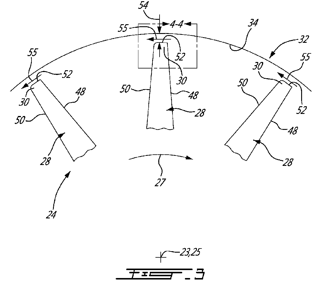
Fig. 3 is schematic front cross-sectional view of the compressor ofFig. 2 , taken along line 3-3 ofFig. 2 ; -
Fig. 4 is a detailed front cross-section view of a rotor blade tip of the compressor ofFig. 2 , taken fromregion 4 inFig. 3 ; -
Fig. 5 is a partial perspective view of a computational fluid dynamics model of tip clearance leakage flow over a rotor blade tip ofFig. 4 having a rounded suction side tip edge; -
Figs. 6a and 6b depict graphs representing the efficiency of rotors having suction side rounded tip edges as described herein relative to baseline rotors (i.e. having non-rounded suction side tip edges), at three different blade tip clearance gaps; and -
Figs. 7a and 7b depict graphs respectively representing the rotor and stage pressure ratios of rotors having blades with suction side rounded tip edges as described herein, relative to baseline rotors (i.e. having non-rounded suction side tip edges), at three different blade tip clearance gaps. -
Fig. 1 illustrates agas turbine engine 10 of a type preferably provided for use in subsonic flight, generally comprising in serial flow communication afan 12 through which ambient air is propelled, amultistage compressor 14 for pressurizing the air, acombustor 16 in which the compressed air is mixed with fuel and ignited for generating an annular stream of hot combustion gases, and aturbine section 18 for extracting energy from the combustion gases. Themultistage compressor section 14 includes anaxial compressor 20, as will be further described. Although a turbofan engine is depicted and described herein, it will be understood however that thegas turbine engine 10 may comprise other types of gas turbine engines such as a turbo-shaft, a turbo-prop, or auxiliary power units. - The
compressor section 14 of thegas turbine engine 10 may be a multi-stage compressor, and thus may comprise several axial and/or centrifugal compressors. Although the present disclosure will focus on anaxial compressor 20, i.e. having an axial turbo machine rotor, it is to be understood that thecompressor 20 as described herein may also be a centrifugal compressor (i.e. impeller) and/or a mixed flow rotor. Further, although the features of the present disclosure are described below with reference to a compressor rotor, it is to be understand that they can be similarly applied to a rotor blade of a turbine. - Referring to
Figs. 2 and 3 , theaxial compressor 20 of thecompressor section 14 comprises generally arotor 24 and astator 22 downstream relative thereto, each having a plurality of blades defined within the gas flow path which is defined by thecompressor inlet passage 42 upstream of therotor 24 and thecompressor discharge passage 21 downstream of thestator 22. The gas flowing indirection 25 is accordingly fed to thecompressor 20 via thecompressor inlet passage 42 and exits therefrom via thecompressor discharge passage 21. Therotor 24 rotates about a central axis ofrotation 23 within the stationary and circumferentially extendingouter shroud 32, the radially inwardly facingwall 34 of which defines a radial outer boundary of the annular gas flow path through thecompressor 20. Therotor 24 includes acentral hub 26 and a plurality ofblades 28 radially extending therefrom and terminating inblade tips 30 immediately adjacent theouter shroud 32. - The rotation of the
compressor rotor 24 is shown inFig. 3 by displacement of therotor blades 28 indirection 27 about thecentral axis 23 and relative to thegas flow direction 25 which is substantially parallel to the longitudinally extendingcentral axis 23. As best seen inFig. 2 , eachblade 28 has a leadingedge 46 and atrailing edge 47. Each of theblades 28 also includes, on opposite sides thereof and separated by the leading andtrailing edges side airfoil surface 48, or simply pressure side, of the blade and a suctionside airfoil surface 50, or suction side, of the blade, as best seen inFig. 3 . The stationaryouter shroud 32, which extends circumferentially and radially surrounds therotor blades 28, includes aninner surface 34 proximate thetips 30 of therotor blades 28. A radial distance between thisinner surface 34 of theshroud 32 and the outer tip surfaces of theblade tips 30 defines thetip clearance gap 54. Anytip leakage flow 55 therefore occurs through the radialtip clearance gap 54, which is radially defined between theinner surface 34 of theouter shroud 32 and theouter end surface 52 of thetips 30 of therotor blades 28. Thetip leakage flow 55 flows in a direction which is opposite to the direction ofrotation 27 of therotors blades 28. - Referring now to
Fig. 4 , eachrotor blade 28 includes arounded tip edge 60 on thesuction side 50 of thetip 30 thereof. This compares, for example, to the more standard and relativelysharper corner 62 formed on thepressure side 48 of theblade tip 30. In other words, the edge formed at the intersection between thetip end surface 52 and thepressure side surface 48 is a relativelysharp corner edge 62, while the edge formed at the intersection between thetip end surface 52 and thesuction side surface 50 at the blade forms a "more rounded" (i.e. having a greater radius of curvature)edge 60. - This more
rounded tip edge 60 formed on thesuction side 50 of therotor blade 28 has been found to be able to reduce the amount of tip leakage flow through thetip clearance gap 54, which as a result, enables a number of potential advantages, including for example only, an increase in rotor efficiency, an increase in rotor flow (choking) capacity, an increase in rotor throttle ability (stall margin), increase rotor tolerance to tip clearance change, and a lower acoustic signature of the engine. - The
rounded tip edge 60 of thesuction side 50 of therotor blades 28 alters the flow structures near the tip clearance gap (radial gap between theouter surface 52 of theblade tips 30 and theinner surface 34 of the surrounding outer shroud 32) and helps to reduce and/or inhibit tip leakage flow. - The
rounded tip edge 60 on thesuction side 50 of theblade tips 30, which has a greater radius of surface than theedge 62 on the pressure side of theblade tips 30, acts as a diffuser whereby leakage flow that emanates from the pressure side of the blade is slowed down before exiting the radialtip clearance gap 54 and mixing with the main gas path flow. This diffuser-caused reduction in leakage flow velocity reduces the mixing losses. - Further, the
rounded edge 60 on thesuction side 50 of theblade tip 30 causes an effectively larger gap size locally at the suction side edge relative to the remainder of thetip clearance gap 54. This larger gap size allows shroud boundary layersecondary flow 66, which occurs in compressors near the casing or shroud in a direction opposite to that of tip leakage flow and is caused by relative motion of the outer case with respect to therotor blades 28, to enter the blade tip gap region more readily. Accordingly, more of thissecondary flow 66 is dragged into thetip clearance gap 54 via the largerrounded tip edge 60, thesecondary flow 66 thereby acting as an obstruction to the leakage flow, which flows in a direction opposite thesecondary flow 66, through thetip clearance gap 54. - A further reason why the
rounded tip edge 60 on the suction side of theblade tips 30 helps reduce tip leakage flow is the formation of a local blockage of centrifugal secondary flow. This centrifugal secondary flow migrates radially outward from hub to shroud along the surface of theblade 28 due to centrifugal force. Theround edge 60 on thesuction side 50 of theblade 28 increases the gap width, as noted above, thereby acting as a diffuser. This diffusion of secondary flow along with the interaction with the jet-like tip clearance flow creates a small aerodynamic "roll up" 64 on the suction side of the blade proximate thetip 30. This roll up 64 forms a local blockage and further helps prevent leakage tip flow. - As can be seen in
Fig. 5 , which depicts computational fluid dynamic (CFD) test results of ablade tip 30 having arounded tip edge 60 on thesuction side 50, the suction side roll up 64 created by therounded edge 60 is evident. This suction side roll up 64 reduces the velocity of thetip leakage flow 55 across theouter surface 52 of theblade tip 30. As is also seen from the CFD results ofFig. 5 , the velocity profile of thetip leakage flow 55 is distorted atregion 57, and the resistance caused by the shroud boundary layer flow on the suction side of the blade tip is evident at 59. - While the
rounded tip edge 60 on thesuction side 50 of theblade tips 30 has at least a greater radius than the muchsharper edge 62 on the pressure side of theblade tips 30, in at least on embodiment the roundedsuction side edge 60 has a radius of between 0.01 inches (0.254 mm) and 0.02 inches (0.508 mm), and more preferably between 0.01 and 0.015 inches (0.254 and 0.381 mm). In one particular embodiment the roundedsuction side edge 60 has a radius of approximately 0.012 inches (0.305 mm). Suchrounded tip edges 60 were found to reduce tip leakage, for the reasons set out above, over a range of different radial tip clearance sizes, for example 0.005" (0.127 mm), 0.01" (0.254 mm) and 0.015" (0.381 mm). In comparison, the pressureside tip edge 62 is substantially sharp or non-rounded, but may have nominal very small radius of approximately 0.003 inches (0.0762 mm). In at least one embodiment, therefore, the radius of the rounded suctionside tip edge 60 is approximately 2 to 6 times larger than the radius of the sharp pressureside tip edge 62. - The presently described blades with suction side rounded tip edges 60 have been found to reduce tip clearance flow losses at a number of different radial tip clearance sizes, and therefore to improve the overall efficiency of rotors having such blades. As shown in
Figs. 6a-6b , the efficiency of rotors having suction side rounded tip edges as described herein relative to baseline rotors (i.e. having non-rounded suction side tip edges) are shown for three different blade tip clearance gaps, namely 0.005" (0.127 mm), 0.01" (0.254 mm) and 0.015" (0.381 mm). As can be seen by the graphs shown inFigs. 6a-6b , the results show efficiency improvement increases toward the choke side, suggesting for example that there is a drop in mixing losses when rotors having suction side rounded tip edges 60 are employed. A reduction in clearance flow would also lead to lower shock losses, reduction in aerodynamic blockage and result in higher flow (choking) capacity. - Because the suction side rounded tip edges 60 have been found to reduce tip clearance flow losses at a number of different radial tip clearance sizes, another advantage is that blades having suction side rounded tip edges 60 thereon can be retrofit into existing compressor and/or turbine designs, thereby enabling existing gas turbine engines to be retrofit, after first production, in order to incorporate rotor blades having such a suction side rounded
tip edge 60 and thus improve the efficiency of their compressors and/or turbines by reducing the rotor tip clearance losses as described above. Further, it is also of note that the efficiency improvements found to be provided with rotor blades having the suction side roundedtip edge 60 hold true for a large number of rotor speeds, making retrofitting various engine designs, rotor speeds, compressor and/or turbine configurations possible. - The suction side rounded
tip edge 60 as described above has also been found to improve the pressure ratios produced by the rotor itself and thus also by the entire compressor and/or turbine stage having such a rotor. More particularly, as shown inFigs. 7a and 7b , on the stall side at higher tip clearances, an extension of stall flow for rotors with rounded suction side tip edges is provided. Accordingly, rotors having suction side rounded tip edges as described herein enable an increase in rotor range, which is important for low speed compressor stability and could also potentially reduce the cost and development time of gas turbine engine compressors. - The above description is meant to be exemplary only, and one skilled in the art will recognize that changes may be made to the embodiments described without departing from the scope of the invention as claimed. For example, as noted above, although the embodiments described relate to an axial compressor, the compressor shroud defined herein may also be employed in a centrifugal compressor or a mixed flow rotor for example. Still other modifications which fall within the scope of the appended claims will be apparent to those skilled in the art, in light of a review of this disclosure.
Claims (14)
- A rotor (24) for a gas turbine engine (10) comprising:a hub (26) defining a central axis of rotation about which the rotor (24) is rotatable and a plurality of blades (28) radially extending from the hub (26), the blades (28) being adapted to project into an annular gas flow passage of said gas turbine engine, each of said blades (28) having a remote blade tip (30) defining an outer tip surface, and a leading edge (46) defined between opposed pressure and suction side airfoil surfaces (48, 50);a shroud (32) circumferentially surrounding the rotor (24) and having a radially inner surface (34) adjacent to the blade tips (30), a radial distance between the inner surface (34) of the shroud (32) and the outer tip surface of the blades (28) defining a radial tip clearance gap (54) therebetween; andthe tip (36) of each of the blades having a pressure side edge (62) formed at a first intersection between the outer tip surface and the pressure side airfoil surface (48), and a suction side edge (60) formed at a second intersection between the outer tip surface and the suction side airfoil surface (50), the pressure side edge (62) having a first radius and the suction side edge (60) having a second radius, the second radius being greater than the first radius, the larger radius suction side edge (60) thereby reducing the amount of tip leakage flow (55) through the radial tip clearance gap (54).
- A rotor (24) for a gas turbine (10) comprising:a hub (26) defining a central axis of rotation about which the rotor (24) is rotatable and a plurality of blades (28) radially extending from the hub (26) to project into the annular gas flow passage, each of said blades (28) having a remote blade tip (30) defining an outer tip surface and a leading edge (46) defined between opposed pressure and suction side airfoil surfaces (48, 50) of the blades (28);a shroud (32) circumferentially surrounding the rotor (24) and having a radially inner surface (34) adjacent to the blade tips (28), a radial distance between the inner surface (34) of the shroud (32) and the outer tip surface of the blades (28) defining a radial tip clearance gap therebetween; andthe tip (30) of each of the blades (28) having a pressure side tip edge (62) formed at a first intersection between the outer tip surface and the pressure side airfoil surface (48), and a suction side tip edge (60) formed at a second intersection between the outer tip surface and the suction side airfoil surface (50), the pressure side tip edge (62) having a first radius and the suction side tip edge (62) having a second radius, the second radius being greater than the first radius, the suction side tip edge (60) thereby being more rounded that the pressure side tip edge (62) and reducing the amount of tip leakage flow through the radial tip clearance gap.
- The rotor as defined in claim 1 or 2, wherein the suction side tip edge (60), which has a greater radius than the pressure side tip edge (62), forms a diffuser which slows down tip leakage flow at the exit of the radial tip clearance gap (54).
- The rotor as defined in any preceding claim, wherein the suction side tip edge (60), which has a greater radius than the pressure side tip edge (62), forms a greater tip clearance gap (54) at the suction side airfoil surface (50) of the blade (28) than at the pressure side airfoil surface (48), the greater tip clearance gap (54) at the suction side (50) of the blade (28) drawing shroud boundary layer secondary flow through the radial tip clearance gap (54) in a direction opposite to said tip leakage flow (55).
- The rotor as defined in any preceding claim, wherein the second radius of said suction side edge (60) is at least 2 times greater than the first radius of said pressure side edge (62).
- The rotor as defined in claim 5, wherein the second radius of the suction side edge (60) is between 2 and 6 times greater than the first radius of the pressure side edge (62).
- The rotor as defined in any preceding claim, wherein the second radius of the suction side edge (60) is between 0.01 inches (0.254 mm) and 0.02 inches (0.508 mm).
- The rotor as defined in claim 7, wherein the second radius of the suction side edge (60) is between 0.01 inches (0.254 mm) and 0.015 inches (0.381 mm).
- The rotor as defined in claim 8, wherein the second radius of the suction side edge is approximately 0.012 inches (0.305 mm).
- A gas turbine engine (10) comprising:a compressor section (14), a combustor (16) and a turbine section (18), in serial flow communication; andat least one of the compressor section (14) and the turbine section (18) defining an annular gas flow passage therethrough and including at least one rotor (24), the rotor being a rotor as defined in any preceding claim.
- The gas turbine engine as defined in claim 10, wherein the rotor (24) is an axial compressor rotor.
- A method of improving gas turbine engine rotor efficiency by reducing tip leakage flow thereof comprising:providing a rotor (24) rotatable about an axis of rotation within an outer shroud (32) surrounding said rotor (24), the rotor having a plurality of radially projecting blades (28) extending into an annular gas flow passage, the annular gas flow passage being radially enclosed by an inner surface (34) of the outer shroud (32), each of said blades (28) having a remote blade tip (30) defining an outer tip surface and a leading edge (46) defined between opposed pressure and suction side airfoil surfaces (48, 50), the inner surface (34) of the shroud (32) being adjacent to the blade tips (30) and a radial distance between the inner surface (34) of the shroud (32) and the outer tip surface of the blades (28) defining a radial tip clearance gap (54) therebetween;rotating said rotor (24) through the annular gas flow passage in a first rotational direction (27) corresponding to a direction of rotation of the rotor (24), a tip leakage flow (55) being formed in the radial tip clearance gap (54), the tip leakage flow (55) being in a direction opposite to the direction (27) of rotation of the rotor (24); andreducing tip leakage flow (55) through the radial tip clearance gap (54) by providing the blades (28) with a suction side tip edge (60), formed at the intersection between the outer tip surface and the suction side airfoil surface (50), that has a greater radius of curvature than a pressure side tip edge (62), formed at the intersection between the outer tip surface and the pressure side airfoil surface (50).
- The method as defined in claim 12, wherein the step of reducing tip leakage further comprises forming a diffuser at the suction side tip edge (60) by slowing down the tip leakage flow (55) at the exit of the radial tip clearance gap (54).
- The method as defined in claim 12 or 13, wherein the step of reducing tip leakage further comprises forming a greater tip clearance gap (54) at the suction side airfoil surface (48) of the blade (28) than at the pressure side airfoil surface (50), the greater tip clearance gap (54) at the suction side (50) of the blade (28) drawing shroud boundary layer secondary flow through the radial tip clearance gap (54) in a direction opposite to said tip leakage flow (55).
Applications Claiming Priority (1)
| Application Number | Priority Date | Filing Date | Title |
|---|---|---|---|
| US13/803,368 US10760499B2 (en) | 2013-03-14 | 2013-03-14 | Turbo-machinery rotors with rounded tip edge |
Publications (2)
| Publication Number | Publication Date |
|---|---|
| EP2778346A1 true EP2778346A1 (en) | 2014-09-17 |
| EP2778346B1 EP2778346B1 (en) | 2022-01-12 |
Family
ID=50277093
Family Applications (1)
| Application Number | Title | Priority Date | Filing Date |
|---|---|---|---|
| EP14159988.6A Active EP2778346B1 (en) | 2013-03-14 | 2014-03-14 | Rotor for a gas turbine engine, corresponding gas turbine engine and method of improving gas turbine engine rotor efficiency |
Country Status (3)
| Country | Link |
|---|---|
| US (1) | US10760499B2 (en) |
| EP (1) | EP2778346B1 (en) |
| CA (1) | CA2846376C (en) |
Families Citing this family (2)
| Publication number | Priority date | Publication date | Assignee | Title |
|---|---|---|---|---|
| US20160238021A1 (en) * | 2015-02-16 | 2016-08-18 | United Technologies Corporation | Compressor Airfoil |
| CN115977999B (en) * | 2023-01-12 | 2024-07-23 | 山东科技大学 | A subsonic compressor, rotor blade and flow stabilization control method |
Citations (3)
| Publication number | Priority date | Publication date | Assignee | Title |
|---|---|---|---|---|
| DE815971C (en) * | 1949-12-22 | 1951-10-08 | Franz Burghauser | Steam or gas turbine blade with little radial clearance loss |
| EP1953344A1 (en) * | 2007-02-05 | 2008-08-06 | Siemens Aktiengesellschaft | Turbine blade |
| US7740445B1 (en) * | 2007-06-21 | 2010-06-22 | Florida Turbine Technologies, Inc. | Turbine blade with near wall cooling |
Family Cites Families (5)
| Publication number | Priority date | Publication date | Assignee | Title |
|---|---|---|---|---|
| US4738586A (en) * | 1985-03-11 | 1988-04-19 | United Technologies Corporation | Compressor blade tip seal |
| US4738568A (en) | 1985-06-11 | 1988-04-19 | Steding Jerry A | Anti-vacuum apparatus and method for installing concrete piles |
| US6672829B1 (en) * | 2002-07-16 | 2004-01-06 | General Electric Company | Turbine blade having angled squealer tip |
| US7281894B2 (en) | 2005-09-09 | 2007-10-16 | General Electric Company | Turbine airfoil curved squealer tip with tip shelf |
| GB201017797D0 (en) * | 2010-10-21 | 2010-12-01 | Rolls Royce Plc | An aerofoil structure |
-
2013
- 2013-03-14 US US13/803,368 patent/US10760499B2/en active Active
-
2014
- 2014-03-13 CA CA2846376A patent/CA2846376C/en active Active
- 2014-03-14 EP EP14159988.6A patent/EP2778346B1/en active Active
Patent Citations (3)
| Publication number | Priority date | Publication date | Assignee | Title |
|---|---|---|---|---|
| DE815971C (en) * | 1949-12-22 | 1951-10-08 | Franz Burghauser | Steam or gas turbine blade with little radial clearance loss |
| EP1953344A1 (en) * | 2007-02-05 | 2008-08-06 | Siemens Aktiengesellschaft | Turbine blade |
| US7740445B1 (en) * | 2007-06-21 | 2010-06-22 | Florida Turbine Technologies, Inc. | Turbine blade with near wall cooling |
Also Published As
| Publication number | Publication date |
|---|---|
| US10760499B2 (en) | 2020-09-01 |
| US20140260324A1 (en) | 2014-09-18 |
| EP2778346B1 (en) | 2022-01-12 |
| CA2846376C (en) | 2023-08-29 |
| CA2846376A1 (en) | 2014-09-14 |
Similar Documents
| Publication | Publication Date | Title |
|---|---|---|
| EP2778427B1 (en) | Compressor bleed self-recirculating system | |
| CN102906429B (en) | For generation of the vortex generator of the vortex of a string compressor blade upstream | |
| EP3179113A1 (en) | Venturi effect endwall treatment | |
| US12320274B2 (en) | Compressor stator with leading edge fillet | |
| JP6421091B2 (en) | Axial flow compressor, gas turbine including the same, and stationary blade of axial flow compressor | |
| US11933193B2 (en) | Turbine engine with an airfoil having a set of dimples | |
| JP2008138678A (en) | The latest booster rotor blade | |
| EP2554793B1 (en) | Inter-turbine ducts with guide vanes of a gas turbine engine | |
| US11346367B2 (en) | Compressor rotor casing with swept grooves | |
| US20160115971A1 (en) | Diffuser pipe with splitter vane | |
| JP2016109124A (en) | Axial compressor endwall treatment for controlling leakage flow | |
| EP3176442B1 (en) | Axial flow device with casing treatment and jet engine | |
| US20170241432A1 (en) | Compressor rotor for supersonic flutter and/or resonant stress mitigation | |
| EP2725233A1 (en) | Rotor blade for a compressor | |
| CA2877222C (en) | Multistage axial flow compressor | |
| EP3098383B1 (en) | Compressor airfoil with compound leading edge profile | |
| US20220042415A1 (en) | Compressor impeller with partially swept leading edge surface | |
| WO2018159681A1 (en) | Turbine and gas turbine | |
| CA2846376C (en) | Turbo-machinery rotors with rounded tip edge | |
| US10900414B2 (en) | Fan assembly having flow recirculation circuit with guide vanes | |
| US11639666B2 (en) | Stator with depressions in gaspath wall adjacent leading edges | |
| US20200165968A1 (en) | Fan assembly having flow recirculation circuit with rotating airfoils | |
| JP2009236121A (en) | Diffuser for diagonal flow compressor | |
| WO2013139404A1 (en) | Blade row for an unsteady axial flow gas turbine stage |
Legal Events
| Date | Code | Title | Description |
|---|---|---|---|
| 17P | Request for examination filed |
Effective date: 20140314 |
|
| AK | Designated contracting states |
Kind code of ref document: A1 Designated state(s): AL AT BE BG CH CY CZ DE DK EE ES FI FR GB GR HR HU IE IS IT LI LT LU LV MC MK MT NL NO PL PT RO RS SE SI SK SM TR |
|
| AX | Request for extension of the european patent |
Extension state: BA ME |
|
| PUAI | Public reference made under article 153(3) epc to a published international application that has entered the european phase |
Free format text: ORIGINAL CODE: 0009012 |
|
| R17P | Request for examination filed (corrected) |
Effective date: 20150317 |
|
| RBV | Designated contracting states (corrected) |
Designated state(s): AL AT BE BG CH CY CZ DE DK EE ES FI FR GB GR HR HU IE IS IT LI LT LU LV MC MK MT NL NO PL PT RO RS SE SI SK SM TR |
|
| STAA | Information on the status of an ep patent application or granted ep patent |
Free format text: STATUS: EXAMINATION IS IN PROGRESS |
|
| 17Q | First examination report despatched |
Effective date: 20190621 |
|
| GRAP | Despatch of communication of intention to grant a patent |
Free format text: ORIGINAL CODE: EPIDOSNIGR1 |
|
| STAA | Information on the status of an ep patent application or granted ep patent |
Free format text: STATUS: GRANT OF PATENT IS INTENDED |
|
| INTG | Intention to grant announced |
Effective date: 20200514 |
|
| GRAJ | Information related to disapproval of communication of intention to grant by the applicant or resumption of examination proceedings by the epo deleted |
Free format text: ORIGINAL CODE: EPIDOSDIGR1 |
|
| STAA | Information on the status of an ep patent application or granted ep patent |
Free format text: STATUS: EXAMINATION IS IN PROGRESS |
|
| INTC | Intention to grant announced (deleted) | ||
| GRAP | Despatch of communication of intention to grant a patent |
Free format text: ORIGINAL CODE: EPIDOSNIGR1 |
|
| STAA | Information on the status of an ep patent application or granted ep patent |
Free format text: STATUS: GRANT OF PATENT IS INTENDED |
|
| INTG | Intention to grant announced |
Effective date: 20210923 |
|
| GRAS | Grant fee paid |
Free format text: ORIGINAL CODE: EPIDOSNIGR3 |
|
| GRAA | (expected) grant |
Free format text: ORIGINAL CODE: 0009210 |
|
| STAA | Information on the status of an ep patent application or granted ep patent |
Free format text: STATUS: THE PATENT HAS BEEN GRANTED |
|
| AK | Designated contracting states |
Kind code of ref document: B1 Designated state(s): AL AT BE BG CH CY CZ DE DK EE ES FI FR GB GR HR HU IE IS IT LI LT LU LV MC MK MT NL NO PL PT RO RS SE SI SK SM TR |
|
| REG | Reference to a national code |
Ref country code: GB Ref legal event code: FG4D |
|
| REG | Reference to a national code |
Ref country code: CH Ref legal event code: EP |
|
| REG | Reference to a national code |
Ref country code: DE Ref legal event code: R096 Ref document number: 602014082131 Country of ref document: DE |
|
| REG | Reference to a national code |
Ref country code: IE Ref legal event code: FG4D |
|
| REG | Reference to a national code |
Ref country code: AT Ref legal event code: REF Ref document number: 1462512 Country of ref document: AT Kind code of ref document: T Effective date: 20220215 |
|
| REG | Reference to a national code |
Ref country code: LT Ref legal event code: MG9D |
|
| REG | Reference to a national code |
Ref country code: NL Ref legal event code: MP Effective date: 20220112 |
|
| REG | Reference to a national code |
Ref country code: AT Ref legal event code: MK05 Ref document number: 1462512 Country of ref document: AT Kind code of ref document: T Effective date: 20220112 |
|
| PG25 | Lapsed in a contracting state [announced via postgrant information from national office to epo] |
Ref country code: NL Free format text: LAPSE BECAUSE OF FAILURE TO SUBMIT A TRANSLATION OF THE DESCRIPTION OR TO PAY THE FEE WITHIN THE PRESCRIBED TIME-LIMIT Effective date: 20220112 |
|
| PG25 | Lapsed in a contracting state [announced via postgrant information from national office to epo] |
Ref country code: SE Free format text: LAPSE BECAUSE OF FAILURE TO SUBMIT A TRANSLATION OF THE DESCRIPTION OR TO PAY THE FEE WITHIN THE PRESCRIBED TIME-LIMIT Effective date: 20220112 Ref country code: RS Free format text: LAPSE BECAUSE OF FAILURE TO SUBMIT A TRANSLATION OF THE DESCRIPTION OR TO PAY THE FEE WITHIN THE PRESCRIBED TIME-LIMIT Effective date: 20220112 Ref country code: PT Free format text: LAPSE BECAUSE OF FAILURE TO SUBMIT A TRANSLATION OF THE DESCRIPTION OR TO PAY THE FEE WITHIN THE PRESCRIBED TIME-LIMIT Effective date: 20220512 Ref country code: NO Free format text: LAPSE BECAUSE OF FAILURE TO SUBMIT A TRANSLATION OF THE DESCRIPTION OR TO PAY THE FEE WITHIN THE PRESCRIBED TIME-LIMIT Effective date: 20220412 Ref country code: LT Free format text: LAPSE BECAUSE OF FAILURE TO SUBMIT A TRANSLATION OF THE DESCRIPTION OR TO PAY THE FEE WITHIN THE PRESCRIBED TIME-LIMIT Effective date: 20220112 Ref country code: HR Free format text: LAPSE BECAUSE OF FAILURE TO SUBMIT A TRANSLATION OF THE DESCRIPTION OR TO PAY THE FEE WITHIN THE PRESCRIBED TIME-LIMIT Effective date: 20220112 Ref country code: ES Free format text: LAPSE BECAUSE OF FAILURE TO SUBMIT A TRANSLATION OF THE DESCRIPTION OR TO PAY THE FEE WITHIN THE PRESCRIBED TIME-LIMIT Effective date: 20220112 Ref country code: BG Free format text: LAPSE BECAUSE OF FAILURE TO SUBMIT A TRANSLATION OF THE DESCRIPTION OR TO PAY THE FEE WITHIN THE PRESCRIBED TIME-LIMIT Effective date: 20220412 |
|
| PG25 | Lapsed in a contracting state [announced via postgrant information from national office to epo] |
Ref country code: PL Free format text: LAPSE BECAUSE OF FAILURE TO SUBMIT A TRANSLATION OF THE DESCRIPTION OR TO PAY THE FEE WITHIN THE PRESCRIBED TIME-LIMIT Effective date: 20220112 Ref country code: LV Free format text: LAPSE BECAUSE OF FAILURE TO SUBMIT A TRANSLATION OF THE DESCRIPTION OR TO PAY THE FEE WITHIN THE PRESCRIBED TIME-LIMIT Effective date: 20220112 Ref country code: GR Free format text: LAPSE BECAUSE OF FAILURE TO SUBMIT A TRANSLATION OF THE DESCRIPTION OR TO PAY THE FEE WITHIN THE PRESCRIBED TIME-LIMIT Effective date: 20220413 Ref country code: FI Free format text: LAPSE BECAUSE OF FAILURE TO SUBMIT A TRANSLATION OF THE DESCRIPTION OR TO PAY THE FEE WITHIN THE PRESCRIBED TIME-LIMIT Effective date: 20220112 Ref country code: AT Free format text: LAPSE BECAUSE OF FAILURE TO SUBMIT A TRANSLATION OF THE DESCRIPTION OR TO PAY THE FEE WITHIN THE PRESCRIBED TIME-LIMIT Effective date: 20220112 |
|
| PG25 | Lapsed in a contracting state [announced via postgrant information from national office to epo] |
Ref country code: IS Free format text: LAPSE BECAUSE OF FAILURE TO SUBMIT A TRANSLATION OF THE DESCRIPTION OR TO PAY THE FEE WITHIN THE PRESCRIBED TIME-LIMIT Effective date: 20220512 |
|
| REG | Reference to a national code |
Ref country code: DE Ref legal event code: R097 Ref document number: 602014082131 Country of ref document: DE |
|
| PG25 | Lapsed in a contracting state [announced via postgrant information from national office to epo] |
Ref country code: SM Free format text: LAPSE BECAUSE OF FAILURE TO SUBMIT A TRANSLATION OF THE DESCRIPTION OR TO PAY THE FEE WITHIN THE PRESCRIBED TIME-LIMIT Effective date: 20220112 Ref country code: SK Free format text: LAPSE BECAUSE OF FAILURE TO SUBMIT A TRANSLATION OF THE DESCRIPTION OR TO PAY THE FEE WITHIN THE PRESCRIBED TIME-LIMIT Effective date: 20220112 Ref country code: RO Free format text: LAPSE BECAUSE OF FAILURE TO SUBMIT A TRANSLATION OF THE DESCRIPTION OR TO PAY THE FEE WITHIN THE PRESCRIBED TIME-LIMIT Effective date: 20220112 Ref country code: MC Free format text: LAPSE BECAUSE OF FAILURE TO SUBMIT A TRANSLATION OF THE DESCRIPTION OR TO PAY THE FEE WITHIN THE PRESCRIBED TIME-LIMIT Effective date: 20220112 Ref country code: EE Free format text: LAPSE BECAUSE OF FAILURE TO SUBMIT A TRANSLATION OF THE DESCRIPTION OR TO PAY THE FEE WITHIN THE PRESCRIBED TIME-LIMIT Effective date: 20220112 Ref country code: DK Free format text: LAPSE BECAUSE OF FAILURE TO SUBMIT A TRANSLATION OF THE DESCRIPTION OR TO PAY THE FEE WITHIN THE PRESCRIBED TIME-LIMIT Effective date: 20220112 Ref country code: CZ Free format text: LAPSE BECAUSE OF FAILURE TO SUBMIT A TRANSLATION OF THE DESCRIPTION OR TO PAY THE FEE WITHIN THE PRESCRIBED TIME-LIMIT Effective date: 20220112 |
|
| REG | Reference to a national code |
Ref country code: CH Ref legal event code: PL |
|
| PLBE | No opposition filed within time limit |
Free format text: ORIGINAL CODE: 0009261 |
|
| STAA | Information on the status of an ep patent application or granted ep patent |
Free format text: STATUS: NO OPPOSITION FILED WITHIN TIME LIMIT |
|
| PG25 | Lapsed in a contracting state [announced via postgrant information from national office to epo] |
Ref country code: AL Free format text: LAPSE BECAUSE OF FAILURE TO SUBMIT A TRANSLATION OF THE DESCRIPTION OR TO PAY THE FEE WITHIN THE PRESCRIBED TIME-LIMIT Effective date: 20220112 |
|
| REG | Reference to a national code |
Ref country code: BE Ref legal event code: MM Effective date: 20220331 |
|
| 26N | No opposition filed |
Effective date: 20221013 |
|
| PG25 | Lapsed in a contracting state [announced via postgrant information from national office to epo] |
Ref country code: LU Free format text: LAPSE BECAUSE OF NON-PAYMENT OF DUE FEES Effective date: 20220314 Ref country code: LI Free format text: LAPSE BECAUSE OF NON-PAYMENT OF DUE FEES Effective date: 20220331 Ref country code: IE Free format text: LAPSE BECAUSE OF NON-PAYMENT OF DUE FEES Effective date: 20220314 Ref country code: CH Free format text: LAPSE BECAUSE OF NON-PAYMENT OF DUE FEES Effective date: 20220331 |
|
| PG25 | Lapsed in a contracting state [announced via postgrant information from national office to epo] |
Ref country code: SI Free format text: LAPSE BECAUSE OF FAILURE TO SUBMIT A TRANSLATION OF THE DESCRIPTION OR TO PAY THE FEE WITHIN THE PRESCRIBED TIME-LIMIT Effective date: 20220112 Ref country code: BE Free format text: LAPSE BECAUSE OF NON-PAYMENT OF DUE FEES Effective date: 20220331 |
|
| P01 | Opt-out of the competence of the unified patent court (upc) registered |
Effective date: 20230530 |
|
| PG25 | Lapsed in a contracting state [announced via postgrant information from national office to epo] |
Ref country code: IT Free format text: LAPSE BECAUSE OF FAILURE TO SUBMIT A TRANSLATION OF THE DESCRIPTION OR TO PAY THE FEE WITHIN THE PRESCRIBED TIME-LIMIT Effective date: 20220112 |
|
| PG25 | Lapsed in a contracting state [announced via postgrant information from national office to epo] |
Ref country code: HU Free format text: LAPSE BECAUSE OF FAILURE TO SUBMIT A TRANSLATION OF THE DESCRIPTION OR TO PAY THE FEE WITHIN THE PRESCRIBED TIME-LIMIT; INVALID AB INITIO Effective date: 20140314 |
|
| PG25 | Lapsed in a contracting state [announced via postgrant information from national office to epo] |
Ref country code: MK Free format text: LAPSE BECAUSE OF FAILURE TO SUBMIT A TRANSLATION OF THE DESCRIPTION OR TO PAY THE FEE WITHIN THE PRESCRIBED TIME-LIMIT Effective date: 20220112 Ref country code: CY Free format text: LAPSE BECAUSE OF FAILURE TO SUBMIT A TRANSLATION OF THE DESCRIPTION OR TO PAY THE FEE WITHIN THE PRESCRIBED TIME-LIMIT Effective date: 20220112 |
|
| PG25 | Lapsed in a contracting state [announced via postgrant information from national office to epo] |
Ref country code: MT Free format text: LAPSE BECAUSE OF FAILURE TO SUBMIT A TRANSLATION OF THE DESCRIPTION OR TO PAY THE FEE WITHIN THE PRESCRIBED TIME-LIMIT Effective date: 20220112 |
|
| PG25 | Lapsed in a contracting state [announced via postgrant information from national office to epo] |
Ref country code: TR Free format text: LAPSE BECAUSE OF FAILURE TO SUBMIT A TRANSLATION OF THE DESCRIPTION OR TO PAY THE FEE WITHIN THE PRESCRIBED TIME-LIMIT Effective date: 20220112 |
|
| PGFP | Annual fee paid to national office [announced via postgrant information from national office to epo] |
Ref country code: GB Payment date: 20260220 Year of fee payment: 13 |
|
| PGFP | Annual fee paid to national office [announced via postgrant information from national office to epo] |
Ref country code: DE Payment date: 20260219 Year of fee payment: 13 |
|
| PGFP | Annual fee paid to national office [announced via postgrant information from national office to epo] |
Ref country code: FR Payment date: 20260219 Year of fee payment: 13 |