EP2778024B1 - Electrically operated power steering device - Google Patents
Electrically operated power steering device Download PDFInfo
- Publication number
- EP2778024B1 EP2778024B1 EP12848277.5A EP12848277A EP2778024B1 EP 2778024 B1 EP2778024 B1 EP 2778024B1 EP 12848277 A EP12848277 A EP 12848277A EP 2778024 B1 EP2778024 B1 EP 2778024B1
- Authority
- EP
- European Patent Office
- Prior art keywords
- voltage
- power source
- assist
- gate driver
- control
- Prior art date
- Legal status (The legal status is an assumption and is not a legal conclusion. Google has not performed a legal analysis and makes no representation as to the accuracy of the status listed.)
- Active
Links
- 230000007423 decrease Effects 0.000 claims description 31
- 239000004065 semiconductor Substances 0.000 claims description 16
- 230000005856 abnormality Effects 0.000 description 26
- 238000010586 diagram Methods 0.000 description 8
- 230000000694 effects Effects 0.000 description 7
- 230000007257 malfunction Effects 0.000 description 6
- 238000013021 overheating Methods 0.000 description 6
- 238000004804 winding Methods 0.000 description 5
- 230000003247 decreasing effect Effects 0.000 description 4
- 230000007246 mechanism Effects 0.000 description 4
- 230000004044 response Effects 0.000 description 4
- 230000004907 flux Effects 0.000 description 3
- 230000005540 biological transmission Effects 0.000 description 1
- 230000008878 coupling Effects 0.000 description 1
- 238000010168 coupling process Methods 0.000 description 1
- 238000005859 coupling reaction Methods 0.000 description 1
- 230000004048 modification Effects 0.000 description 1
- 238000012986 modification Methods 0.000 description 1
- 238000005070 sampling Methods 0.000 description 1
- 229920006395 saturated elastomer Polymers 0.000 description 1
Images


Classifications
-
- B—PERFORMING OPERATIONS; TRANSPORTING
- B62—LAND VEHICLES FOR TRAVELLING OTHERWISE THAN ON RAILS
- B62D—MOTOR VEHICLES; TRAILERS
- B62D5/00—Power-assisted or power-driven steering
- B62D5/04—Power-assisted or power-driven steering electrical, e.g. using an electric servo-motor connected to, or forming part of, the steering gear
- B62D5/0457—Power-assisted or power-driven steering electrical, e.g. using an electric servo-motor connected to, or forming part of, the steering gear characterised by control features of the drive means as such
- B62D5/0481—Power-assisted or power-driven steering electrical, e.g. using an electric servo-motor connected to, or forming part of, the steering gear characterised by control features of the drive means as such monitoring the steering system, e.g. failures
- B62D5/0484—Power-assisted or power-driven steering electrical, e.g. using an electric servo-motor connected to, or forming part of, the steering gear characterised by control features of the drive means as such monitoring the steering system, e.g. failures for reaction to failures, e.g. limp home
-
- B—PERFORMING OPERATIONS; TRANSPORTING
- B62—LAND VEHICLES FOR TRAVELLING OTHERWISE THAN ON RAILS
- B62D—MOTOR VEHICLES; TRAILERS
- B62D5/00—Power-assisted or power-driven steering
- B62D5/04—Power-assisted or power-driven steering electrical, e.g. using an electric servo-motor connected to, or forming part of, the steering gear
- B62D5/0457—Power-assisted or power-driven steering electrical, e.g. using an electric servo-motor connected to, or forming part of, the steering gear characterised by control features of the drive means as such
- B62D5/0481—Power-assisted or power-driven steering electrical, e.g. using an electric servo-motor connected to, or forming part of, the steering gear characterised by control features of the drive means as such monitoring the steering system, e.g. failures
Definitions
- the present invention relates to an electric power steering apparatus.
- an electric power steering apparatus which has a brushless DC motor serving as a drive source.
- an EPS incorporates an inverter device for driving a brushless DC motor.
- the inverter device comprises six semiconductor switching elements (FETs): three on the battery side, and three on the ground side.
- FETs semiconductor switching elements
- an EPS includes a gate driver power source separately from the battery.
- the conventional EPS is not provided with a means for specifying whether abnormality is caused by an FET or by a gate driver in a case where any abnormality occurs in motor control. Therefore, for example, in a case where only one phase of a brushless DC motor is disconnected due to an FET malfunction, assist control has to be stopped even though assist control using the remaining normal phases is possible. In a word, in the conventional EPS, control of switching between assist control and assist stop control is not appropriately exerted depending on a factor of abnormality in motor control.
- US 2005/258792 A1 discloses an electric power-assisted device and transmission ratio-variable steering unit.
- US 2005/258792 A1 relates to the concept of producing a sufficiently boosted voltage even when the supplied voltage becomes high, indeed US 2005/258792 discloses an electric power steering apparatus comprising: a motor configured to apply assist force to a steering system; a torque sensor configured to detect steering torque applied to the steering system; an inverter device including a semiconductor switching element and configured to drive the motor by driving the semiconductor switching element; a gate driver power source configured to supply power to a gate drive circuit that drives the inverter device; and a controller configured to control the inverter device based on the steering torque, wherein, based on an indication of a voltage decrease in the gate driver power source, the controller switches assist control, for applying the assist force to the steering system, to assist stop control, for stopping the assist control.
- WO 2009/125269 discloses an electric power steering device including an electric power source that includes a main electric power source and a subsidiary electric power source.
- WO 2009/125269 describes that when the main electric power source fails (loses its capacity of supplying source power), the subsidiary electric power source is used so as to singly supply source power to the motor drive circuit.
- the subsidiary electric power source holds and provides driver's safety.
- the upper-limit electric power Pmax of the electric motor is progressively increased from zero to the upper-limit electric power Pmax (Vx).
- the upper-limit electrics power Pmax is gradually lessened and then the assist control is discontinued.
- an electric power steering apparatus is provided according to claim 1 or 7.
- assist control can be switched to assist stop control.
- assist control can be switched to assist stop control.
- a factor other than abnormality in the voltage of the gate driver power source for example, where only one phase of a brushless DC motor is disconnected, but assist control using the remaining normal phases is possible, assist control can be continued. Therefore, depending on a factor of abnormality in motor control, switching between assist control and assist stop control can be controlled appropriately.
- the indication of the voltage decrease in the gate driver power source is given by the difference between the voltage of the gate driver power source and the power source voltage of the inverter device If the voltage of the gate driver power source is equal to or higher than a voltage threshold value with respect to the power source voltage of the inverter device, the controller exerts assist control, and if not equal to or higher than the voltage threshold value, the controller exerts assist stop control.
- the indication of the voltage decrease in the gate driver power source is given by the difference between the voltage of the gate driver power source and the power source voltage of the inverter device. Accordingly, based on whether or not the voltage of the gate driver power source is maintained at a higher level than the power source voltage of the inverter device, the state of the voltage of the gate driver power source can be determined. Thus, an area of voltage where assist control is possible can be broadened, in comparison with the case of switching between assist control and assist stop control based only on the voltage of the gate driver power source. Additionally, in this configuration, the voltage decrease of the gate driver power source with respect to the power source voltage of the inverter can be determined based on the voltage threshold value.
- the voltage of the gate driver power source can be divided into an area of normal voltage and an area of voltage lower than a normal value.
- the area of voltage in the gate driver power source can be divided using the threshold value, control of switching between assist control and assist stop control can be exerted more accurately.
- the indication of the voltage decrease in the gate driver power source is given by the voltage of the gate driver power source. If the voltage of the gate driver power source is equal to or higher than a voltage threshold value, the controller exerts assist control, and if lower than the voltage threshold value, the controller exerts assist stop control.
- the voltage decrease in the gate driver power source is determined based on the voltage threshold value.
- the controller exerts assist limit control in which assist control is exerted while limiting an electric current command value corresponding to a target assist force, and that the controller exerts the assist limit control based on the indication of the voltage decrease in the gate driver power source.
- the controller is able to exert assist limit control based on the indication of the voltage decrease in the gate driver power source.
- assist limit control is exerted, thereby restricting the value of the electric current flowing in the motor.
- the semiconductor switching element of the inverter device can be prevented from overheating and thereby leading to malfunction.
- the controller exerts assist control if the indication of the voltage decrease in the gate driver power source is equal to or greater than a first voltage threshold value, exerts assist limit control if the indication is less than the first voltage threshold value but greater than a second voltage threshold value that is smaller than the first voltage threshold value, and exerts assist stop control if the indication is equal to or less than the second voltage threshold value.
- the state of the voltage of the gate driver power source can be determined based on the first voltage threshold value and the second voltage threshold value set smaller than the first voltage threshold value. That is, the voltage of the gate driver power source can be divided into an area of normal voltage, an area of voltage slightly lower than a normal value, and an area of voltage significantly lower than the normal value. Since the voltage area of the gate driver power source is divided using the two threshold values, control of switching between assist control, assist limit control, and assist stop control can be exerted more accurately.
- the controller decreases drive frequency of the semiconductor switching element based on the indication of the voltage decrease in the gate driver power source.
- the drive frequency of the semiconductor switching element is decreased based on the indication of the voltage decrease in the gate driver power source, thus making it possible to prevent the semiconductor switching element of the inverter device from overheating and thereby leading to malfunction. That is, the same advantageous effects can be yielded as those in assist limit control.
- the controller decreases the power source voltage of the inverter device based on the indication of the voltage decrease in the gate driver power source.
- the power source voltage of the inverter device is decreased based on the indication of the voltage decrease in the gate driver power source, thus making it possible to prevent the semiconductor switching element of the inverter device from overheating and thereby leading to malfunction. That is, the same advantageous effects can be yielded as those in assist limit control.
- a steering wheel 2 is fixed to a steering shaft 3 and also coupled to a rack shaft 5 via a rack and pinion mechanism 4.
- the steering shaft 3 rotates. Then, the rotation of the steering shaft 3 is converted into reciprocal linear motion of the rack shaft 5 by the rack and pinion mechanism 4.
- the steering shaft 3 includes a column shaft 3a, intermediate shaft 3b, and pinion shaft 3c coupled together.
- a torsion bar 17 is attached to an intermediate part of the column shaft 3a.
- Tie rods 6 are coupled to both ends of the rack shaft 5. The linear motion of the rack shaft 5 is transmitted to a knuckle, not shown, via the tie rods 6. Consequently, the steering angle of wheels 7 to be turned is changed, and thus the traveling direction of the vehicle is changed.
- the EPS 1 includes an EPS actuator 10 and an ECU 11 for controlling operation of the EPS actuator 10.
- the EPS actuator 10 applies assist force to the steering system of the vehicle in order to assist a driver with operation of the steering wheel 2.
- the EPS actuator 10 is configured as an EPS actuator of column type.
- the EPS actuator 10 includes a motor 12 serving as a drive source, and a decelerating mechanism 13 coupling the motor 12 and the column shaft 3a.
- a brushless DC motor is employed as the motor 12 .
- the EPS actuator 10 decelerates rotation of the motor 12 by the decelerating mechanism 13 and transmits the decelerated rotation to the column shaft 3a.
- the torque of the motor 12 is applied to the steering system as assist force.
- a torque sensor 14, motor rotation angle sensor 34, and in-vehicle network CN such as CAN (Controller Area Network) are connected to the ECU 11.
- a signal output from a vehicle speed sensor 15 is input to the ECU 11 via the in-vehicle network CN.
- the torque sensor 14 is a torque sensor that outputs signals Sa and Sb from sensors in a plurality of systems.
- the torque sensor 14 includes a sensor core, not shown, and two sensor elements 14a and 14b.
- the sensor core generates a magnetic flux that changes based on torsion of the torsion bar 17.
- Each of the sensor elements 14a and 14b is formed from a hole IC, which is a magnetoelectric transducer, and is disposed around the sensor core.
- the torque sensor 14 outputs voltages output from the sensor elements 14a and 14b, which have been changed with changes in magnetic flux, to the ECU 11 as sensor signals Sa and Sb, respectively.
- the ECU 11 calculates target assist force based on a vehicle state quantity, which is detected by the various sensors.
- the ECU 11 supplies drive power to the motor 12 in order to cause the EPS actuator 10 to generate the target assist force.
- the ECU 11 exerts assist control to control assist force to be applied to the steering system.
- the ECU 11 includes a microcomputer 16, a power source relay 24, a switching regulator 28, a gate driver power source 29, a gate driver circuit 31, and an inverter device 32.
- Power from the battery 20 is supplied to the ECU 11 through a fuse 21, or through a fuse 22 and an ignition switch (hereinafter referred to as IGSW) 23.
- the fuse 21 is connected to the power source relay 24.
- the FET 25 serving as a semiconductor switching element.
- the FET 25 is controlled by the microcomputer 16.
- the power source relay 24 is opened and closed by the FET 25.
- the output terminal of the power source 24 is connected to a diode 26 and the inverter device 32.
- the output terminal of the IGSW 23 is connected to a diode 27.
- the output terminal of the diode 26 is joined to the output terminal of the diode 27. Additionally, both of the diodes 26 and 27 are connected to the switching regulator 28 and the gate driver power source 29 on the output side. Power is supplied to the microcomputer 16 from the switching regulator 28. Power is supplied to the gate driver circuit 31 from the gate driver power source 29.
- Voltage Vg of the gate driver power source 29 is taken into the A/D terminal 66 of the microcomputer 16 from a point d, which is midway between the gate driver power source 29 and the gate driver circuit 31.
- the microcomputer 16 outputs a motor control signal from a PWM output part 65 to the gate driver circuit 31.
- the gate driver circuit 31 outputs a gate signal to the inverter device 32 based on the motor control signal, and drives the respective gates of the FETs included in the inverter device 32. Based on a gate signal input to the gate of each FET, the inverter device 32 supplies drive power to the motor 12. A predetermined voltage is applied to the three-phase winding of the motor 12 by the inverter device 32.
- the inverter device 32 comprises six FETs, serving as semiconductor switching elements, in correspondence with the number of the phases of the motor 12. Specifically, the inverter device 32 includes a series circuit of FETs 41a and 41d, a series circuit of FETs 41b and 41e, and a series circuit of FETs 41c and 41f, which three series circuits are connected in parallel.
- the contact point 42u between the FETs 41a and 41d is connected to the U-phase coil of the motor 12.
- the contact point 42v between the FETs 41b and 41e is connected to the V-phase coil of the motor 12.
- the contact point 42w between the FETs 41c and 41f is connected to the W-phase coil of the motor 12.
- the inverter device 32 is provided with current sensors 43u, 43v, and 43w for detecting phase current values Iu, Iv, and Iw, respectively, flowing in the motor 12.
- the FETs 41d, 41e, and 41f are grounded via the current sensors 43u, 43v, and 43w, respectively.
- the FETs 41a, 41b, and 41c are connected to the battery 20 via the power source relay 24, fuse 21, and the like.
- the gate driver circuit 31 converts a motor control signal output from the microcomputer 16, into a voltage at which each gate of the FETs 41a to 41f can be driven.
- the gate driver circuit 31 outputs, as a gate signal, the converted voltage and applies this voltage to the gate terminal of each of the FETs 41a to 41f.
- each of the FETs 41a to 41f is turned on/off in response to the motor control signal.
- a DC voltage supplied from the battery 20 is converted into drive power of three phases (U, V, and W) and this drive power is supplied to the motor 12.
- the microcomputer 16 detects phase current values Iu, Iv, and Iw flowing in the motor 12 based on their respective signals output from the current sensors 43u, 43v, and 43w, respectively.
- the microcomputer 16 detects the motor rotation angle ⁇ m of the motor 12 based on a signal output from the motor rotation angle sensor 34.
- the microcomputer 16 detects steering torque ⁇ based on sensor signals Sa and Sb output from the torque sensor 14.
- the microcomputer 16 detects vehicle speed V based on a signal output from the vehicle speed sensor 15 received via the in-vehicle network CN. Based on the detected phase current values Iu, Iv, and Iw, motor rotation angle ⁇ m, steering torque ⁇ , and vehicle speed V, the microcomputer 16 generates a motor control signal and outputs this signal to the gate driver circuit 31.
- the microcomputer 16 includes: a calculating section 35 that calculates an electric current command value Iq*, an output section 36 that outputs a motor control signal based on the electric current command value Iq*, and an abnormality determining section 37.
- the abnormality determining section 37 determines the state of the voltage Vg of the gate driver power source 29, taken from an A/D terminal 66. Specifically, the abnormality determining section 37 determines whether or not the voltage Vg is equal to or higher than a voltage threshold value ⁇ 0 . Based on the result of the determination, the abnormality determining section 37 generates a switching signal Sva for switching the electric current command value Iq* output from the calculating section 35 to the output section 36. The abnormality determining section 37 outputs the switching signal Sva indicating the state of the voltage Vg, to the calculating section 35.
- the calculating section 35 calculates the target assist force to be generated by the EPS actuator 10 based on steering torque ⁇ and vehicle speed V.
- the calculating section 35 calculates an electric current command value Iq** for motor torque corresponding to the target assist force. Therefore, the calculating section 35 has a calculation map 50 representing the relationship among steering torque ⁇ , vehicle speed V, and electric current command value Iq**.
- the calculating section 35 also includes a command value memory, not shown, for outputting "0" as an electric current command value Iq**.
- the calculating section 35 includes a switching section 52 that operates in response to a switching signal Sva and switches the electric current command value Iq* to be output to the output section 36.
- the switching section 52 includes a contact point 52a connected to the calculation map 50, a contact point 52n connected to a command value memory, and a contact point 52c connected to the output section 36. Based on a switching signal Sva from the abnormality determining section 37, the switching section 52 is switched as follows. If the voltage Vg of the gate driver power source 29 is equal to or higher than the voltage threshold value ⁇ 0, the switching section 52 connects the contact points 52a and 52c. As a result, the electric current command value Iq** output from the calculation map 50 is output from the calculating section 35 to the output section 36 as it is, as an electric current command value Iq*.
- phase current values Iu, Iv, and Iw and motor rotation angle ⁇ m are input to the output section 36.
- the phase current values Iu, Iv, and Iw and the motor rotation angle ⁇ m are input to the three-phase/two-phase converting section 60 of the output section 36.
- the three-phase/two-phase converting section 60 calculates d-axis current Id and q-axis current Iq by converting the phase current values Iu, Iv, and Iw into coordinates based on the motor rotation angle ⁇ m.
- a q-axis deviation calculating section 61q finds a q-axis deviation ⁇ Iq between an electric current command value Iq*, serving as a q-axis target current, and q-axis current Iq.
- the d-axis deviation ⁇ Id is subjected to calculating processing by a d-axis F/B control section 62d, and a d-axis voltage command value Vd* is output from the d-axis F/B control section 62d.
- the q-axis deviation ⁇ Iq is subjected to calculating processing by a q-axis F/B control section 62q, and a q-axis voltage command value Vq* is output from the q-axis F/B control section 62q.
- the two-phase/three-phase converting section 63 converts the d-axis voltage command value Vd* and q-axis voltage command value Vq* into coordinates based on the motor rotation angle ⁇ m. Thereby, the two-phase-/three-phase converting section 63 calculates voltage command values Vu*, Vv*, and Vw*, respectively corresponding to the U-phase winding, V-phase winding, and W-phase winding.
- the PWM converting section 64 generates a PWM control signal for each phase, which is a pulse signal.
- the PWM control signals for the corresponding phases have duty ratios Du, Dv, and Dw, respectively corresponding to the voltage command values Vu*, Vv*, and Vw*.
- a PWM output section 65 converts PWM control signals for the corresponding phases, which have been generated in the PWM converting section 64, into signal levels able to be input to the gate driver circuit 31, and thereby generates motor control signals.
- the output section 36 exerts electric current feedback control in the d/q coordinate system. Then, a motor control signal determined based on the electric current feedback control is output to the gate driver circuit 31 from the output section 36. Consequently, voltages corresponding to the d-axis voltage command value Vd* and q-axis voltage command value Vq* are applied to the three-phase winding of the motor 12 from the inverter device 32, thereby rotating the motor 12.
- control flow for assist control by the abnormality determining section 37 will be described referring to Fig.7 .
- the control flow is repeated at predetermined sampling period.
- the microcomputer 16 takes in the voltage Vg of the gate driver power source 29 (step S101).
- the microcomputer 16 determines whether or not the voltage Vg of the gate driver power source 29 is equal to or higher than the voltage threshold value ⁇ 0 (step S102). If the voltage Vg of the gate driver power source 29 is equal to or higher than the voltage threshold value ⁇ 0 (step S102: YES), the microcomputer 16 determines that the voltage Vg is normal. Then, based on the result of the determination, the microcomputer 16 connects the contact points 52a and 52c of the switching section 52, exerts regular assist control (step S103), and thereby ends the control flow.
- step S102 determines that the voltage Vg of the gate driver power source 29 is lower than a normal value. Then, based on the result of the determination, the microcomputer 16 connects the contact points 52n and 52c of the switching section 52, exerts assist stop control (step S104), and thereby ends the control flow.
- the voltage decrease of the gate driver power source 29 can be determined based on the voltage threshold value ⁇ 0 . That is, by dividing the voltage of the gate driver power source 29 into an area of normal voltage and an area of voltage lower than the normal value, control of switching between assist control and assist stop control can be exerted more accurately.
- a calculating section 135 includes a limiting map 51 that limits an electric current command value Iq** output from a calculation map 50.
- a switching section 152 includes a contact point 152a connected to the calculation map 50, a contact point 152n connected to a command value memory, a contact point 152b connected to a limiting map 51, and a contact point 152c connected to an output section 36. Based on the state of the voltage Vg of a gate driver power source 29, the switching section 152 is switched as follows. If the voltage Vg of the gate driver power source 29 is equal to or higher than a first voltage threshold value ⁇ 1 , the switching section 152 connects a contact point 152a and a contact point 152c. Consequently, the electric current command value Iq** output from the calculation map 50 is output from the calculating section 135 to the output section 36 as it is, as an electric current command value Iq*.
- a microcomputer 16 takes in the voltage Vg of the gate driver power source 29 (step S201).
- the microcomputer 16 determines whether or not the voltage Vg of the gate driver power source 29 is equal to or higher than the first voltage threshold value ⁇ 1 (step S202). If the voltage Vg is equal to or higher than the first voltage threshold value ⁇ 1 (step S202: YES), the microcomputer 16 determines that the voltage Vg is normal. Then, based on the result of the determination, the microcomputer 16 connects the contact points 152a and 152c of the switching section 152, exerts regular assist control (step S203), and thereby ends control flow.
- step S204 determines whether or not the voltage Vg is equal to or lower than the second voltage threshold value ⁇ 2 (step S204). If the voltage Vg is higher than the voltage threshold value ⁇ 2 (step S204: YES), the microcomputer 16 determines that the voltage Vg of the gate driver power source 29 is slightly lower than a normal value. Then, based on the result of the determination, the microcomputer 16 connects the contact points 152b and 152c of the switching section 152, exerts assist limit control (step S205), and thereby ends control flow.
- step 204 determines that the voltage Vg of the gate driver power source 29 is significantly lower than the normal value. Then, based on the result of the determination, the microcomputer 16 connects the contact points 152n and 152c of the switching section 152, exerts assist stop control (step S206), and thereby ends control flow.
- the microcomputer 16 determines that the voltage Vg is normal, and exerts regular assist control. If the voltage Vg is higher than the second voltage threshold value ⁇ 2 but lower than the first voltage threshold value ⁇ 1 , the microcomputer 16 determines that the voltage Vg is slightly lower than the normal value, and exerts assist limit control. Further, if the voltage Vg is equal to or lower than the second voltage threshold value ⁇ 2 , the microcomputer 16 determines that the voltage Vg is significantly lower than the normal value, and exerts assist stop control.
- the microcomputer 16 exerts assist limit control, thereby restricting the values of phase currents flowing in the motor 12 and enabling continued application of assist force.
- the FETs which are semiconductor switching elements of the inverter device 32, are prevented from overheating, which may lead to a malfunction, and application of assist force can be continued.
- the state of the voltage Vg of the gate driver power source 29 can be determined based on the first voltage threshold value ⁇ 1 and the second voltage threshold value ⁇ 2 set lower than the first one. That is, by dividing the voltage Vg of the gate driver power source 29 into an area of normal voltage, an area of voltage slightly lower than a normal value, and an area of voltage significantly lower than the normal value, control of switching between assist control, assist limit control, and assist stop control can be exerted more accurately.
- the power source voltage Vb of an inverter device 32 is taken into an A/D terminal 66 of a microcomputer 16 from a point d2, which is midway between a power source relay 24 and the inverter device 32, after divided by voltage dividing resistances R3 and R4.
- the voltage Vg of a gate driver power source 29 is taken into the A/D terminal 66 from a point d1, which is midway between the gate driver power source 29 and a gate driver circuit 31, after divided by voltage dividing resistances R1 and R2.
- an abnormality determining section 37 determines the state of the voltage Vg of the gate driver power source 29 with respect to the power source voltage Vb of the inverter device 32. Specifically, the abnormality determining section 37 determines whether or not the difference between the voltage Vg and the power source voltage Vb is equal to or greater than a voltage threshold value ⁇ 0 .
- the abnormality determining section 37 generates a switching signal Sva for switching an electric current command value Iq* output from a calculating section 35 to an output section 36, and outputs this switching signal to the calculating section 35.
- a switching section 52 is switched as follows. If a difference between the voltage Vg and power source voltage Vb is equal to or greater than the voltage threshold value ⁇ 0 , the switching section 52 connects a contact point 52a and a contact point 52c. Consequently, an electric current command value Iq** output from a calculation map 50 is output from the calculating section 35 to the output section 36 as it is, as an electric current command value Iq*.
- a microcomputer 16 takes in the voltage Vg of the gate driver power source 29 (step S301).
- the microcomputer 16 takes in the power source voltage Vb of the inverter device 32 (step S302).
- the microcomputer 16 determines whether or not a difference between the voltage Vg and the power source voltage Vb is equal to or greater than the voltage threshold value ⁇ 0 (step S303). If the difference between the voltage Vg and power source voltage Vb is equal to or greater than the voltage threshold value ⁇ 0 (step S303: YES), the microcomputer 16 determines that the voltage Vg is maintained at a sufficiently high level with respect to the power source voltage Vb and is, therefore, normal. Based on the result of the determination, the microcomputer 16 connects the contact points 52a and 52c of the switching section 52, exerts regular assist control (step S304), and thereby ends control flow.
- step S303: NO If the difference between the voltage Vg and power source voltage Vb is less than the voltage threshold value ⁇ 0 (step S303: NO), the microcomputer 16 determines that the voltage Vg is not maintained at a sufficiently high level with respect to the power source voltage Vb and is, therefore, lower than a normal value. Then, based on the result of the determination, the microcomputer 16 connects the contact points 52n and 52c of the switching section 52, exerts assist stop control (step S305), and thereby ends control flow.
- assist stop control may be exerted even in an area of voltage where the inverter device 32 can be driven.
- the voltage Vg is higher than the power source voltage Vb by the voltage threshold value ⁇ 0 . Therefore, while the inverter device 32 is able to be driven, assist stop control is exerted due to the voltage Vg lower than the voltage threshold value ⁇ 0 .
- the microcomputer 16 determines that the voltage Vg is maintained at a sufficiently high level with respect to the power source voltage Vb and is, therefore, normal. Then, based on the result of the determination, the microcomputer 16 exerts regular assist control. Conversely, if a difference between the voltage Vg and the power source voltage Vb is less than the voltage threshold value ⁇ 0 , the microcomputer 16 determines that the voltage Vg is not maintained at a sufficiently high level with respect to the power source voltage Vb and is, therefore, less than a normal value. Then, based on the result of the determination, the microcomputer 16 exerts assist stop control.
- an indication of a decrease in the voltage Vg of the gate driver power source 29 is given by the difference between the voltage Vg of the gate driver power source 29 and the power source voltage Vb of the inverter device 32. Therefore, the state of the voltage Vg of the gate driver power source 29 can be determined based on whether or not the voltage Vg of the gate driver power source 29 is maintained at a sufficiently higher level than the power source voltage Vb of the inverter device 32, that is, whether or not the voltage Vg of the gate driver power source 29 is a voltage at which the inverter device 32 can be driven. Therefore, an area of voltage where assist control is possible can be broadened, in comparison with the case of switching between assist control and assist stop control based on only the voltage Vg of the gate driver power source 29. Thus, according to any factor of abnormality in motor control, control of switching between assist control and assist stop control can be exerted more accurately.
- any decrease in the voltage Vg of the gate driver power source 29 with respect to the power source voltage Vb of the inverter device 32 can be determined based on the voltage threshold value ⁇ 0 . That is, by dividing the voltage Vg of the gate driver power source 29 with respect to the power source voltage Vb of the inverter device 32 into the area of normal voltage and the area of voltage lower than a normal value, control of switching between assist control and assist stop control can be exerted more accurately.
- a switching section 152 is switched as follows. If a difference between the voltage Vg and the power source voltage Vb is equal to or greater than a first voltage threshold value ⁇ 1 , the switching section 152 connects a contact point 152a and a contact point 152c. Consequently, an electric current command value Iq** output from a calculation map 50 is output from a calculating section 135 to an output section 36 as it is, as an electric current command value Iq*.
- the switching section 152 connects the contact point 152b and the contact point 152c.
- the electric current command value Iq** output from the calculation map 50 is limited to a predetermined level by a limiting map 51.
- the limited electric current command value Iq* is output from the calculating section 135 to the output section 36 as an electric current command value Iq*.
- a microcomputer 16 takes in the voltage Vg of the gate driver power source 29 (step S401).
- the microcomputer 16 takes in the power source voltage Vb of the inverter device 32 (step S402).
- the microcomputer 16 determines whether or not a difference between the voltage Vg and the power source voltage Vb is equal to or greater than the first voltage threshold value ⁇ 1 (step S403). If the difference between the voltage Vg and power source voltage Vb is equal to or greater than the first voltage threshold value ⁇ 1 (step S403: YES), the microcomputer 16 determines that the voltage Vg is maintained at a sufficiently high level with respect to the power source voltage Vb and is, therefore, normal. Then, based on the result of the determination, the microcomputer 16 connects the contact point 152a and the contact point 152c of the switching section 152, exerts regular assist control (step S404), and thereby ends control flow.
- step S403 If the difference between the voltage Vg and the power source voltage Vb is less than the first voltage threshold value ⁇ 1 (step S403: NO), the microcomputer 16 determines whether the difference between the Vg and power source voltage Vb is equal to or less than the second voltage threshold value ⁇ 2 (step S405). If the difference between the voltage Vg and power source voltage Vb is greater than the second voltage threshold value ⁇ 2 (step S405: NO), the microcomputer 16 determines that the voltage Vg is not maintained at a sufficiently high level with respect to the power source voltage Vb and is slightly less than a normal value. Then, based on the result of the determination, the microcomputer 16 connects the contact points 152b and 152c of the switching section 152, exerts assist limit control (step S406), and thereby ends control flow.
- step 405 YES
- the microcomputer 16 determines that the voltage Vg is not maintained at a sufficiently high level with respect to the power source voltage Vb and is significantly less than a normal value. Then, based on the result of the determination, the microcomputer 16 connects the contact points 152n and 152c of the switching section 152, exerts assist stop control (step S407), and thereby ends control flow.
- the microcomputer 16 exerts assist limit control to prevent overheating of FETs. Instead of this, switching loss may be reduced by decreasing the drive frequency of each FET. In this case, the power source voltage Vb of the inverter device 32 can be decreased to maintain the saturated state of the FET even if the voltage of the gate driver power source 29 decreases.
- This modification also applies to the fourth embodiment.
- assist limit control is exerted using both the limiting map 51 that limits the electric current command value Iq** output from the calculation map 50, and the switching section 52 that switches the electric current command value Iq* in response to a switching signal Sva.
- assist limit control is not limited to such a configuration.
- a limit-value limiting map may be provided, which has a limit value proportional to the voltage of the gate driver power source 29.
- a selecting section may be provided for comparing an electric current command limit value output from the limit-value limiting map, and an electric current command value Iq**, and selecting a smaller one.
- Assist limit control in such a configuration also prevents overheating of FETs.
- the third embodiment as an indication of a decrease in the voltage Vg of the gate driver power source 29, a difference between the voltage Vg of the gate driver power source 29 and the power source voltage Vb of the inverter device 32 is used.
- the ratio of the voltage Vg of the gate driver power source 29 to the power source voltage Vb of the inverter device 32 may be used.
- assist control may be exerted on condition that a value calculated from the voltage Vg/power source voltage Vb is equal to or higher than a specific value
- assist stop control may be exerted on condition that the value is less than the specific value.
- switching between assist control, assist limit control, and assist stop control may be carried out using the ratio of the voltage Vg of the gate driver power source 29 to the power source voltage Vb of the inverter device 32.
- a brushless DC motor is used as a drive source for the EPS actuator 10, and an inverter device is used for driving the brushless DC motor.
- a brush DC motor may be used instead of the brushless DC motor.
- an H bridge circuit may be included to drive the brush DC motor.
- the present invention is implemented in the EPS 1 of column type.
- the present invention may be applied to an EPS of pinion or rack assist type.
- the present invention maybe applied in, for example, a numerical control device for a machine tool, or a control device for a robot.
Description
- The present invention relates to an electric power steering apparatus.
- In recent years, vehicles have been equipped with power steering apparatus for assisting a driver's steering operation. As a power steering apparatus, an electric power steering apparatus (EPS) is widely used, which has a brushless DC motor serving as a drive source. Generally, an EPS incorporates an inverter device for driving a brushless DC motor.
- Power for an inverter device is supplied by a battery mounted in a vehicle. The inverter device comprises six semiconductor switching elements (FETs): three on the battery side, and three on the ground side. In order to drive the three FETs on the battery side, voltage higher than the battery voltage has to be supplied to the respective gates of these FETs. For this reason, an EPS includes a gate driver power source separately from the battery.
- However, the conventional EPS is not provided with a means for specifying whether abnormality is caused by an FET or by a gate driver in a case where any abnormality occurs in motor control. Therefore, for example, in a case where only one phase of a brushless DC motor is disconnected due to an FET malfunction, assist control has to be stopped even though assist control using the remaining normal phases is possible. In a word, in the conventional EPS, control of switching between assist control and assist stop control is not appropriately exerted depending on a factor of abnormality in motor control.
-
US 2005/258792 A1 discloses an electric power-assisted device and transmission ratio-variable steering unit.US 2005/258792 A1 relates to the concept of producing a sufficiently boosted voltage even when the supplied voltage becomes high, indeedUS 2005/258792 discloses an electric power steering apparatus comprising: a motor configured to apply assist force to a steering system; a torque sensor configured to detect steering torque applied to the steering system; an inverter device including a semiconductor switching element and configured to drive the motor by driving the semiconductor switching element; a gate driver power source configured to supply power to a gate drive circuit that drives the inverter device; and a controller configured to control the inverter device based on the steering torque, wherein, based on an indication of a voltage decrease in the gate driver power source, the controller switches assist control, for applying the assist force to the steering system, to assist stop control, for stopping the assist control.WO 2009/125269 discloses an electric power steering device including an electric power source that includes a main electric power source and a subsidiary electric power source.WO 2009/125269 describes that when the main electric power source fails (loses its capacity of supplying source power), the subsidiary electric power source is used so as to singly supply source power to the motor drive circuit. Also, inWO 2009/125269 , by taking into account an efficient use of an electric power the subsidiary electric power source holds and provides driver's safety. As described in the description andFig. 5 , the upper-limit electric power Pmax of the electric motor is progressively increased from zero to the upper-limit electric power Pmax (Vx). In addition, immediately after the vehicle stops running, the upper-limit electrics power Pmax is gradually lessened and then the assist control is discontinued. - It is an object of the present invention to provide an electric power steering apparatus able to appropriately exert control of switching between assist control and assist stop control depending on a factor of abnormality in motor control.
- To solve the foregoing problem, according to the first aspect of the present invention, an electric power steering apparatus is provided according to
claim - In this configuration, based on an indication of a voltage decrease in the gate driver power source, assist control can be switched to assist stop control. With thus determining the state of the voltage of the gate driver power source, in a case where a factor other than abnormality in the voltage of the gate driver power source is present, for example, where only one phase of a brushless DC motor is disconnected, but assist control using the remaining normal phases is possible, assist control can be continued. Therefore, depending on a factor of abnormality in motor control, switching between assist control and assist stop control can be controlled appropriately.
- In the foregoing electric power steering apparatus, the indication of the voltage decrease in the gate driver power source is given by the difference between the voltage of the gate driver power source and the power source voltage of the inverter device If the voltage of the gate driver power source is equal to or higher than a voltage threshold value with respect to the power source voltage of the inverter device, the controller exerts assist control, and if not equal to or higher than the voltage threshold value, the controller exerts assist stop control.
- In this configuration, the indication of the voltage decrease in the gate driver power source is given by the difference between the voltage of the gate driver power source and the power source voltage of the inverter device. Accordingly, based on whether or not the voltage of the gate driver power source is maintained at a higher level than the power source voltage of the inverter device, the state of the voltage of the gate driver power source can be determined. Thus, an area of voltage where assist control is possible can be broadened, in comparison with the case of switching between assist control and assist stop control based only on the voltage of the gate driver power source. Additionally, in this configuration, the voltage decrease of the gate driver power source with respect to the power source voltage of the inverter can be determined based on the voltage threshold value. That is, the voltage of the gate driver power source can be divided into an area of normal voltage and an area of voltage lower than a normal value. Thus, since the area of voltage in the gate driver power source can be divided using the threshold value, control of switching between assist control and assist stop control can be exerted more accurately.
- In the foregoing electric power steering apparatus, the indication of the voltage decrease in the gate driver power source is given by the voltage of the gate driver power source. If the voltage of the gate driver power source is equal to or higher than a voltage threshold value, the controller exerts assist control, and if lower than the voltage threshold value, the controller exerts assist stop control.
- In this configuration, the voltage decrease in the gate driver power source is determined based on the voltage threshold value. Thereby, the same advantageous effects as those of the invention described in claim 2 can be yielded.
- In the foregoing electric power steering apparatus, the controller exerts assist limit control in which assist control is exerted while limiting an electric current command value corresponding to a target assist force, and that the controller exerts the assist limit control based on the indication of the voltage decrease in the gate driver power source.
- In this configuration, the controller is able to exert assist limit control based on the indication of the voltage decrease in the gate driver power source. Thus, in an area of voltage where the voltage of the gate driver power source is slightly lower than a normal value, assist limit control is exerted, thereby restricting the value of the electric current flowing in the motor. Thus, the semiconductor switching element of the inverter device can be prevented from overheating and thereby leading to malfunction.
- In the foregoing electric power steering apparatus, the controller exerts assist control if the indication of the voltage decrease in the gate driver power source is equal to or greater than a first voltage threshold value, exerts assist limit control if the indication is less than the first voltage threshold value but greater than a second voltage threshold value that is smaller than the first voltage threshold value, and exerts assist stop control if the indication is equal to or less than the second voltage threshold value.
- In this configuration, the state of the voltage of the gate driver power source can be determined based on the first voltage threshold value and the second voltage threshold value set smaller than the first voltage threshold value. That is, the voltage of the gate driver power source can be divided into an area of normal voltage, an area of voltage slightly lower than a normal value, and an area of voltage significantly lower than the normal value. Since the voltage area of the gate driver power source is divided using the two threshold values, control of switching between assist control, assist limit control, and assist stop control can be exerted more accurately.
- In the foregoing electric power steering apparatus, it is preferable that the controller decreases drive frequency of the semiconductor switching element based on the indication of the voltage decrease in the gate driver power source.
- In this configuration, the drive frequency of the semiconductor switching element is decreased based on the indication of the voltage decrease in the gate driver power source, thus making it possible to prevent the semiconductor switching element of the inverter device from overheating and thereby leading to malfunction. That is, the same advantageous effects can be yielded as those in assist limit control.
- In the foregoing electric power steering apparatus, it is preferable that the controller decreases the power source voltage of the inverter device based on the indication of the voltage decrease in the gate driver power source.
- In this configuration, the power source voltage of the inverter device is decreased based on the indication of the voltage decrease in the gate driver power source, thus making it possible to prevent the semiconductor switching element of the inverter device from overheating and thereby leading to malfunction. That is, the same advantageous effects can be yielded as those in assist limit control.
-
-
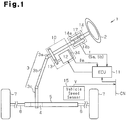
Fig.1 is a schematic diagram of the configuration of an electric power steering apparatus according to the first embodiment of the present invention; -
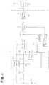
Fig.2 is a block diagram of the configuration of the power source of the electric power steering apparatus; -
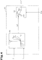
Fig.3 is a block diagram of the electrical configuration of the electric power steering apparatus; -
Fig.4 is a block diagram of the electrical configuration of a calculating section of the electric power steering apparatus; -
Fig.5 is a graph showing an area of voltage where assist control is exerted and an area of voltage where assist stop control is exerted; -
Fig.6 is a block diagram of the electrical configuration of an output section of the electric power steering apparatus; -
Fig.7 is a flowchart illustrating control exerted by an abnormality determining section of the electric power steering apparatus; -
Fig.8 is a block diagram of the electrical configuration of a calculating section of an electric power steering apparatus according to the second embodiment of the present invention; -
Fig.9 is a graph showing an area of voltage where assist control is exerted, an area of voltage where assist limit control is exerted, and an area of voltage where assist stop control is exerted; -
Fig.10 is a flowchart illustrating control exerted by an abnormality determining section of the electric power steering apparatus; -
Fig.11 is a block diagram of the power source configuration of an electric power steering apparatus according to the third embodiment of the present invention; -
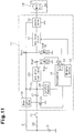
Fig.12 is a block diagram of the electrical configuration of the electric power steering apparatus; -
Fig.13 is a graph showing an area of voltage where assist control is exerted and an area of voltage where assist stop control is exerted; -
Fig.14 is a flowchart illustrating control exerted by an abnormality determining section of the electric power steering apparatus; -
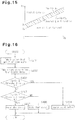
Fig.15 is a graph showing respective areas of voltage where assist control, assist limit control, and assist stop control are respectively exerted in an electric power steering apparatus according to the fourth embodiment of the present invention; and -
Fig.16 is a flowchart illustrating control exerted by an abnormality determining section of the electric power steering apparatus. - The first embodiment in which the present invention is implemented in an electric power steering apparatus (EPS) of column type will now be described with reference to
Figs.1 to 7 . - As shown in
Fig.1 , a steering wheel 2 is fixed to asteering shaft 3 and also coupled to arack shaft 5 via a rack andpinion mechanism 4. In response to a driver's operation of the steering wheel 2, the steeringshaft 3 rotates. Then, the rotation of thesteering shaft 3 is converted into reciprocal linear motion of therack shaft 5 by the rack andpinion mechanism 4. - The steering
shaft 3 includes acolumn shaft 3a, intermediate shaft 3b, andpinion shaft 3c coupled together. Atorsion bar 17 is attached to an intermediate part of thecolumn shaft 3a.Tie rods 6 are coupled to both ends of therack shaft 5. The linear motion of therack shaft 5 is transmitted to a knuckle, not shown, via thetie rods 6. Consequently, the steering angle ofwheels 7 to be turned is changed, and thus the traveling direction of the vehicle is changed. - The
EPS 1 includes anEPS actuator 10 and anECU 11 for controlling operation of theEPS actuator 10. TheEPS actuator 10 applies assist force to the steering system of the vehicle in order to assist a driver with operation of the steering wheel 2. - The
EPS actuator 10 is configured as an EPS actuator of column type. TheEPS actuator 10 includes amotor 12 serving as a drive source, and adecelerating mechanism 13 coupling themotor 12 and thecolumn shaft 3a. As themotor 12, a brushless DC motor is employed. TheEPS actuator 10 decelerates rotation of themotor 12 by thedecelerating mechanism 13 and transmits the decelerated rotation to thecolumn shaft 3a. Thus, the torque of themotor 12 is applied to the steering system as assist force. - A
torque sensor 14, motorrotation angle sensor 34, and in-vehicle network CN such as CAN (Controller Area Network) are connected to theECU 11. A signal output from avehicle speed sensor 15 is input to theECU 11 via the in-vehicle network CN. Thetorque sensor 14 is a torque sensor that outputs signals Sa and Sb from sensors in a plurality of systems. Thetorque sensor 14 includes a sensor core, not shown, and twosensor elements torsion bar 17. Each of thesensor elements torsion bar 17 is twisted as a result of torque input into thesteering shaft 3, a magnetic flux passed through each of thesensor elements torque sensor 14 outputs voltages output from thesensor elements ECU 11 as sensor signals Sa and Sb, respectively. - The
ECU 11 calculates target assist force based on a vehicle state quantity, which is detected by the various sensors. TheECU 11 supplies drive power to themotor 12 in order to cause theEPS actuator 10 to generate the target assist force. Thus, theECU 11 exerts assist control to control assist force to be applied to the steering system. - Next, referring to
Figs.2 and3 , the power source configuration and electrical configuration of theEPS 1 will be described. - As shown in
Fig.2 , theECU 11 includes amicrocomputer 16, apower source relay 24, a switchingregulator 28, a gatedriver power source 29, agate driver circuit 31, and aninverter device 32. Power from thebattery 20 is supplied to theECU 11 through afuse 21, or through afuse 22 and an ignition switch (hereinafter referred to as IGSW) 23. Thefuse 21 is connected to thepower source relay 24. - Between the
power source relay 24 and themicrocomputer 16 is anFET 25 serving as a semiconductor switching element. TheFET 25 is controlled by themicrocomputer 16. Thepower source relay 24 is opened and closed by theFET 25. The output terminal of thepower source 24 is connected to adiode 26 and theinverter device 32. The output terminal of theIGSW 23 is connected to adiode 27. - The output terminal of the
diode 26 is joined to the output terminal of thediode 27. Additionally, both of thediodes regulator 28 and the gatedriver power source 29 on the output side. Power is supplied to themicrocomputer 16 from the switchingregulator 28. Power is supplied to thegate driver circuit 31 from the gatedriver power source 29. - Voltage Vg of the gate
driver power source 29 is taken into the A/D terminal 66 of themicrocomputer 16 from a point d, which is midway between the gatedriver power source 29 and thegate driver circuit 31. On the other hand, themicrocomputer 16 outputs a motor control signal from aPWM output part 65 to thegate driver circuit 31. - As shown in
Fig.3 , thegate driver circuit 31 outputs a gate signal to theinverter device 32 based on the motor control signal, and drives the respective gates of the FETs included in theinverter device 32. Based on a gate signal input to the gate of each FET, theinverter device 32 supplies drive power to themotor 12. A predetermined voltage is applied to the three-phase winding of themotor 12 by theinverter device 32. - The
inverter device 32 comprises six FETs, serving as semiconductor switching elements, in correspondence with the number of the phases of themotor 12. Specifically, theinverter device 32 includes a series circuit ofFETs FETs FETs 41c and 41f, which three series circuits are connected in parallel. Thecontact point 42u between the FETs 41a and 41d is connected to the U-phase coil of themotor 12. Thecontact point 42v between the FETs 41b and 41e is connected to the V-phase coil of themotor 12. Thecontact point 42w between the FETs 41c and 41f is connected to the W-phase coil of themotor 12. - Additionally, the
inverter device 32 is provided withcurrent sensors motor 12. TheFETs current sensors Figs.2 and3 , theFETs battery 20 via thepower source relay 24,fuse 21, and the like. - The
gate driver circuit 31 converts a motor control signal output from themicrocomputer 16, into a voltage at which each gate of the FETs 41a to 41f can be driven. Thegate driver circuit 31 outputs, as a gate signal, the converted voltage and applies this voltage to the gate terminal of each of the FETs 41a to 41f. Thus, each of the FETs 41a to 41f is turned on/off in response to the motor control signal. As a result, a DC voltage supplied from thebattery 20 is converted into drive power of three phases (U, V, and W) and this drive power is supplied to themotor 12. - The
microcomputer 16 detects phase current values Iu, Iv, and Iw flowing in themotor 12 based on their respective signals output from thecurrent sensors microcomputer 16 detects the motor rotation angle θm of themotor 12 based on a signal output from the motorrotation angle sensor 34. Themicrocomputer 16 detects steering torque τ based on sensor signals Sa and Sb output from thetorque sensor 14. Themicrocomputer 16 detects vehicle speed V based on a signal output from thevehicle speed sensor 15 received via the in-vehicle network CN. Based on the detected phase current values Iu, Iv, and Iw, motor rotation angle θm, steering torque τ, and vehicle speed V, themicrocomputer 16 generates a motor control signal and outputs this signal to thegate driver circuit 31. - The
microcomputer 16 includes: a calculatingsection 35 that calculates an electric current command value Iq*, anoutput section 36 that outputs a motor control signal based on the electric current command value Iq*, and anabnormality determining section 37. Theabnormality determining section 37 determines the state of the voltage Vg of the gatedriver power source 29, taken from an A/D terminal 66. Specifically, theabnormality determining section 37 determines whether or not the voltage Vg is equal to or higher than a voltage threshold value α0. Based on the result of the determination, theabnormality determining section 37 generates a switching signal Sva for switching the electric current command value Iq* output from the calculatingsection 35 to theoutput section 36. Theabnormality determining section 37 outputs the switching signal Sva indicating the state of the voltage Vg, to the calculatingsection 35. - As shown in
Figs.4 and5 , the calculatingsection 35 calculates the target assist force to be generated by theEPS actuator 10 based on steering torque τ and vehicle speed V. The calculatingsection 35 calculates an electric current command value Iq** for motor torque corresponding to the target assist force. Therefore, the calculatingsection 35 has acalculation map 50 representing the relationship among steering torque τ, vehicle speed V, and electric current command value Iq**. The calculatingsection 35 also includes a command value memory, not shown, for outputting "0" as an electric current command value Iq**. Additionally, the calculatingsection 35 includes aswitching section 52 that operates in response to a switching signal Sva and switches the electric current command value Iq* to be output to theoutput section 36. - The switching
section 52 includes acontact point 52a connected to thecalculation map 50, acontact point 52n connected to a command value memory, and acontact point 52c connected to theoutput section 36. Based on a switching signal Sva from theabnormality determining section 37, the switchingsection 52 is switched as follows. If the voltage Vg of the gatedriver power source 29 is equal to or higher than the voltage threshold value α0, the switchingsection 52 connects thecontact points calculation map 50 is output from the calculatingsection 35 to theoutput section 36 as it is, as an electric current command value Iq*. - Conversely, if the voltage Vg is lower than the voltage threshold value α0, the switching
section 52 connects thecontact point 52n and contact point52c. Consequently, an electric current command value Iq** (=0) output from the command value memory is output from the calculatingsection 35 to theoutput section 36 as an electric current command value Iq*. Subsequently, themicrocomputer 16 exerts assist stop control and stops drive of themotor 12. - As shown in
Fig.6 , not only an electric command value Iq* from the calculatingsection 35, but also phase current values Iu, Iv, and Iw and motor rotation angle θm are input to theoutput section 36. Specifically, the phase current values Iu, Iv, and Iw and the motor rotation angle θm are input to the three-phase/two-phase converting section 60 of theoutput section 36. The three-phase/two-phase converting section 60 calculates d-axis current Id and q-axis current Iq by converting the phase current values Iu, Iv, and Iw into coordinates based on the motor rotation angle θm. - A d-axis
deviation calculating section 61d finds a d-axis deviation ΔId between a d-axis target current Id* (in the present embodiment, Id* = 0) and a d-axis current Id. Similarly, a q-axis deviation calculating section 61q finds a q-axis deviation ΔIq between an electric current command value Iq*, serving as a q-axis target current, and q-axis current Iq. The d-axis deviation ΔId is subjected to calculating processing by a d-axis F/B control section 62d, and a d-axis voltage command value Vd* is output from the d-axis F/B control section 62d. Also, the q-axis deviation ΔIq is subjected to calculating processing by a q-axis F/B control section 62q, and a q-axis voltage command value Vq* is output from the q-axis F/B control section 62q. - The two-phase/three-
phase converting section 63 converts the d-axis voltage command value Vd* and q-axis voltage command value Vq* into coordinates based on the motor rotation angle θm. Thereby, the two-phase-/three-phase converting section 63 calculates voltage command values Vu*, Vv*, and Vw*, respectively corresponding to the U-phase winding, V-phase winding, and W-phase winding. - The
PWM converting section 64 generates a PWM control signal for each phase, which is a pulse signal. The PWM control signals for the corresponding phases have duty ratios Du, Dv, and Dw, respectively corresponding to the voltage command values Vu*, Vv*, and Vw*. APWM output section 65 converts PWM control signals for the corresponding phases, which have been generated in thePWM converting section 64, into signal levels able to be input to thegate driver circuit 31, and thereby generates motor control signals. - Thus, based on the electric current command value Iq*, phase current values Iu, Iv, and Iw and motor rotation angle θm, the
output section 36 exerts electric current feedback control in the d/q coordinate system. Then, a motor control signal determined based on the electric current feedback control is output to thegate driver circuit 31 from theoutput section 36. Consequently, voltages corresponding to the d-axis voltage command value Vd* and q-axis voltage command value Vq* are applied to the three-phase winding of themotor 12 from theinverter device 32, thereby rotating themotor 12. - Next, a control flow for assist control by the
abnormality determining section 37 will be described referring toFig.7 . The control flow is repeated at predetermined sampling period. - As shown
Fig.7 , first, themicrocomputer 16 takes in the voltage Vg of the gate driver power source 29 (step S101). Next, themicrocomputer 16 determines whether or not the voltage Vg of the gatedriver power source 29 is equal to or higher than the voltage threshold value α0(step S102). If the voltage Vg of the gatedriver power source 29 is equal to or higher than the voltage threshold value α0(step S102: YES), themicrocomputer 16 determines that the voltage Vg is normal. Then, based on the result of the determination, themicrocomputer 16 connects thecontact points switching section 52, exerts regular assist control (step S103), and thereby ends the control flow. - If the voltage Vg of the gate
driver power source 29 is lower than the voltage threshold value α0(step S102: NO), themicrocomputer 16 determines that the voltage Vg of the gatedriver power source 29 is lower than a normal value. Then, based on the result of the determination, themicrocomputer 16 connects the contact points 52n and 52c of theswitching section 52, exerts assist stop control (step S104), and thereby ends the control flow. - According to the foregoing first embodiment, advantageous effects as described below can be obtained.
- (1) If the voltage Vg of the gate
driver power source 29 is equal to or higher than the voltage threshold value α0, themicrocomputer 16 determines that the voltage Vg is normal and exerts regular assist control. Conversely, if the voltage Vg is lower than the voltage threshold value α0, themicrocomputer 16 determines that the voltage Vg is lower than the normal value and exerts assist stop control. - With this configuration, based on the voltage Vg of the gate
driver power source 29, switching between assist control and assist stop control can be exerted. With thus determining the state of the voltage of the gatedriver power source 29, in a case where any other factor than abnormality in the voltage of the gatedriver power source 29 is detected, for example, where only one phase of themotor 12 is disconnected, but assist control using the remaining normal phases is possible, assist control can be continued. Therefore, depending on a factor of abnormality in the motor control, switching between assist control and assist stop control can be exerted appropriately. - Additionally, with this configuration, the voltage decrease of the gate
driver power source 29 can be determined based on the voltage threshold value α0. That is, by dividing the voltage of the gatedriver power source 29 into an area of normal voltage and an area of voltage lower than the normal value, control of switching between assist control and assist stop control can be exerted more accurately. - Next, referring to
Figs. 8 to 10 , the second embodiment according to the present invention will be described. In the second embodiment, detailed descriptions of parts identical to those in the first embodiment are omitted. - As shown in
Fig.8 , a calculatingsection 135 includes a limitingmap 51 that limits an electric current command value Iq** output from acalculation map 50. Aswitching section 152 includes a contact point 152a connected to thecalculation map 50, acontact point 152n connected to a command value memory, acontact point 152b connected to a limitingmap 51, and acontact point 152c connected to anoutput section 36. Based on the state of the voltage Vg of a gatedriver power source 29, theswitching section 152 is switched as follows. If the voltage Vg of the gatedriver power source 29 is equal to or higher than a first voltage threshold value α1, theswitching section 152 connects a contact point 152a and acontact point 152c. Consequently, the electric current command value Iq** output from thecalculation map 50 is output from the calculatingsection 135 to theoutput section 36 as it is, as an electric current command value Iq*. - Conversely, if the voltage Vg is higher than a second voltage threshold value α2 but lower than the first voltage threshold value α1, the
switching section 152 connects thecontact point 152b andcontact point 152c. Consequently, the electric current command value Iq** output from the calculatingmap 50 is limited to a predetermined level by the limitingmap 51. Then, the limited electric current command value Iq* is output from the calculatingsection 135 to theoutput section 36, as an electric current command value Iq* (assist limit control). If the voltage Vg is equal to or lower than the second voltage threshold value α2, theswitching section 152 connects thecontact point 152c andcontact point 152n. Consequently, the electric current command value Iq** (= 0) output from the command value memory is output from the calculatingsection 135 to theoutput section 36, as an electric current command value Iq* (assist stop control). - Next, referring to
Fig.10 , control flow for assist control by anabnormality determining section 37 will be described. - As shown in
Fig.10 , first, amicrocomputer 16 takes in the voltage Vg of the gate driver power source 29 (step S201). Next, themicrocomputer 16 determines whether or not the voltage Vg of the gatedriver power source 29 is equal to or higher than the first voltage threshold value α1(step S202). If the voltage Vg is equal to or higher than the first voltage threshold value α1(step S202: YES), themicrocomputer 16 determines that the voltage Vg is normal. Then, based on the result of the determination, themicrocomputer 16 connects the contact points 152a and 152c of theswitching section 152, exerts regular assist control (step S203), and thereby ends control flow. - Conversely, if the voltage Vg is lower than the first voltage threshold value α1(step S202: NO), the
microcomputer 16 determines whether or not the voltage Vg is equal to or lower than the second voltage threshold value α2(step S204). If the voltage Vg is higher than the voltage threshold value α2(step S204: YES), themicrocomputer 16 determines that the voltage Vg of the gatedriver power source 29 is slightly lower than a normal value. Then, based on the result of the determination, themicrocomputer 16 connects the contact points 152b and 152c of theswitching section 152, exerts assist limit control (step S205), and thereby ends control flow. - Conversely, if the voltage Vg is equal to or lower than the second voltage threshold value α2(step 204: NO), the
microcomputer 16 determines that the voltage Vg of the gatedriver power source 29 is significantly lower than the normal value. Then, based on the result of the determination, themicrocomputer 16 connects the contact points 152n and 152c of theswitching section 152, exerts assist stop control (step S206), and thereby ends control flow. - According to the foregoing second embodiment, advantageous effects as described below can be obtained.
- (2) In the
EPS 1, in an area of voltage where the voltage of the gatedriver power source 29 is slightly lower than the normal value, FETs of aninverter device 32 become unsaturated. If electric current flows in amotor 12 continuously in this state, the FETs may overheat, leading to malfunction. - In this regard, according to the second embodiment, if the voltage Vg of the gate
driver power source 29 is equal to or higher than the first threshold value α1, themicrocomputer 16 determines that the voltage Vg is normal, and exerts regular assist control. If the voltage Vg is higher than the second voltage threshold value α2 but lower than the first voltage threshold value α1, themicrocomputer 16 determines that the voltage Vg is slightly lower than the normal value, and exerts assist limit control. Further, if the voltage Vg is equal to or lower than the second voltage threshold value α2, themicrocomputer 16 determines that the voltage Vg is significantly lower than the normal value, and exerts assist stop control. - In this configuration, in the area where the voltage Vg of the gate
driver power source 29 is slightly lower than a normal value, themicrocomputer 16 exerts assist limit control, thereby restricting the values of phase currents flowing in themotor 12 and enabling continued application of assist force. Thus, the FETs, which are semiconductor switching elements of theinverter device 32, are prevented from overheating, which may lead to a malfunction, and application of assist force can be continued. - Additionally, in this configuration, the state of the voltage Vg of the gate
driver power source 29 can be determined based on the first voltage threshold value α1 and the second voltage threshold value α2 set lower than the first one. That is, by dividing the voltage Vg of the gatedriver power source 29 into an area of normal voltage, an area of voltage slightly lower than a normal value, and an area of voltage significantly lower than the normal value, control of switching between assist control, assist limit control, and assist stop control can be exerted more accurately. - Next, referring to
Fig.4 andFigs.11 to 14 , the third embodiment according to the present invention will be described. In the third embodiment, detailed descriptions of parts identical to those in the first embodiment are omitted. - As shown in
Fig.11 , the power source voltage Vb of aninverter device 32 is taken into an A/D terminal 66 of amicrocomputer 16 from a point d2, which is midway between apower source relay 24 and theinverter device 32, after divided by voltage dividing resistances R3 and R4. Also, the voltage Vg of a gatedriver power source 29 is taken into the A/D terminal 66 from a point d1, which is midway between the gatedriver power source 29 and agate driver circuit 31, after divided by voltage dividing resistances R1 and R2. - As shown in
Fig.12 , based on a difference between the voltage Vg of the gatedriver power source 29 and the power source voltage Vb of theinverter device 32, which are taken into the A/D terminal 66, anabnormality determining section 37 determines the state of the voltage Vg of the gatedriver power source 29 with respect to the power source voltage Vb of theinverter device 32. Specifically, theabnormality determining section 37 determines whether or not the difference between the voltage Vg and the power source voltage Vb is equal to or greater than a voltage threshold value β0. Then, based on the result of the determination, theabnormality determining section 37 generates a switching signal Sva for switching an electric current command value Iq* output from a calculatingsection 35 to anoutput section 36, and outputs this switching signal to the calculatingsection 35. - As shown in
Figs.4 and13 , based on the state of the voltage Vg of the gatedriver power source 29 with respect to the power source voltage Vb of theinverter device 32, aswitching section 52 is switched as follows. If a difference between the voltage Vg and power source voltage Vb is equal to or greater than the voltage threshold value β0, the switchingsection 52 connects acontact point 52a and acontact point 52c. Consequently, an electric current command value Iq** output from acalculation map 50 is output from the calculatingsection 35 to theoutput section 36 as it is, as an electric current command value Iq*. - Conversely, if a difference between the voltage Vg and the power source voltage Vb is less than the voltage threshold value β0, the switching
section 52 connects thecontact point 52n and thecontact point 52c. Consequently, an electric current command value Iq** (= 0) output from a command value memory is output from the calculatingsection 35 to theoutput section 36, as an electric current command value Iq* (assist stop control). - Next, referring to
Fig. 14 , a control flow for assist control by theabnormality determining section 37 will be described. - As shown in
Fig.14 , first, amicrocomputer 16 takes in the voltage Vg of the gate driver power source 29 (step S301). Next, themicrocomputer 16 takes in the power source voltage Vb of the inverter device 32 (step S302). Subsequently, themicrocomputer 16 determines whether or not a difference between the voltage Vg and the power source voltage Vb is equal to or greater than the voltage threshold value β0(step S303). If the difference between the voltage Vg and power source voltage Vb is equal to or greater than the voltage threshold value β0(step S303: YES), themicrocomputer 16 determines that the voltage Vg is maintained at a sufficiently high level with respect to the power source voltage Vb and is, therefore, normal. Based on the result of the determination, themicrocomputer 16 connects thecontact points switching section 52, exerts regular assist control (step S304), and thereby ends control flow. - If the difference between the voltage Vg and power source voltage Vb is less than the voltage threshold value β0(step S303: NO), the
microcomputer 16 determines that the voltage Vg is not maintained at a sufficiently high level with respect to the power source voltage Vb and is, therefore, lower than a normal value. Then, based on the result of the determination, themicrocomputer 16 connects the contact points 52n and 52c of theswitching section 52, exerts assist stop control (step S305), and thereby ends control flow. - According to the foregoing third embodiment, advantageous effects as described below can be obtained.
- (3) In the first and second embodiments, to determine the state of the voltage Vg of the gate
driver power source 29, the voltage Vg of the gatedriver power source 29 alone is used, without taking the power voltage Vb of theinverter device 32 into consideration. That is, if the voltage Vg is lower than the voltage threshold value α0 or equal to or less than the second threshold value α2, assist stop control is exerted without exception, regardless of the value of the power source voltage Vb. - In these configurations, while it can be determined to a certain degree whether the voltage Vg of the gate
driver power source 29 is higher or lower than a normal value, assist stop control may be exerted even in an area of voltage where theinverter device 32 can be driven. For example, in the area of voltage indicated by the shaded portion inFig.13 , the voltage Vg is higher than the power source voltage Vb by the voltage threshold value β0. Therefore, while theinverter device 32 is able to be driven, assist stop control is exerted due to the voltage Vg lower than the voltage threshold value α0. - In this regard, according to the third embodiment, if the difference between the voltage Vg of the gate
driver power source 29 and the power source voltage Vb of theinverter device 32 is equal to or greater than the voltage threshold value β0, themicrocomputer 16 determines that the voltage Vg is maintained at a sufficiently high level with respect to the power source voltage Vb and is, therefore, normal. Then, based on the result of the determination, themicrocomputer 16 exerts regular assist control. Conversely, if a difference between the voltage Vg and the power source voltage Vb is less than the voltage threshold value β0, themicrocomputer 16 determines that the voltage Vg is not maintained at a sufficiently high level with respect to the power source voltage Vb and is, therefore, less than a normal value. Then, based on the result of the determination, themicrocomputer 16 exerts assist stop control. - In this configuration, an indication of a decrease in the voltage Vg of the gate
driver power source 29 is given by the difference between the voltage Vg of the gatedriver power source 29 and the power source voltage Vb of theinverter device 32. Therefore, the state of the voltage Vg of the gatedriver power source 29 can be determined based on whether or not the voltage Vg of the gatedriver power source 29 is maintained at a sufficiently higher level than the power source voltage Vb of theinverter device 32, that is, whether or not the voltage Vg of the gatedriver power source 29 is a voltage at which theinverter device 32 can be driven. Therefore, an area of voltage where assist control is possible can be broadened, in comparison with the case of switching between assist control and assist stop control based on only the voltage Vg of the gatedriver power source 29. Thus, according to any factor of abnormality in motor control, control of switching between assist control and assist stop control can be exerted more accurately. - Additionally, in this configuration, any decrease in the voltage Vg of the gate
driver power source 29 with respect to the power source voltage Vb of theinverter device 32 can be determined based on the voltage threshold value β0. That is, by dividing the voltage Vg of the gatedriver power source 29 with respect to the power source voltage Vb of theinverter device 32 into the area of normal voltage and the area of voltage lower than a normal value, control of switching between assist control and assist stop control can be exerted more accurately. - Referring to
Figs.8 ,15, and 16 , the fourth embodiment according to the present invention will be described below. In the fourth embodiment, detailed descriptions of parts identical to those in the third embodiment are omitted. - As shown in
Figs.8 and15 , based on the state of the voltage Vg of a gatedriver power source 29 with respect to the power source voltage Vb of aninverter device 32, aswitching section 152 is switched as follows. If a difference between the voltage Vg and the power source voltage Vb is equal to or greater than a first voltage threshold value β1, theswitching section 152 connects a contact point 152a and acontact point 152c. Consequently, an electric current command value Iq** output from acalculation map 50 is output from a calculatingsection 135 to anoutput section 36 as it is, as an electric current command value Iq*. - Conversely, if a difference between the voltage Vg and the power source voltage Vb is greater than a second voltage threshold value β2 but less than the first voltage threshold value β1, the
switching section 152 connects thecontact point 152b and thecontact point 152c. As a result, the electric current command value Iq** output from thecalculation map 50 is limited to a predetermined level by a limitingmap 51. Then, the limited electric current command value Iq* is output from the calculatingsection 135 to theoutput section 36 as an electric current command value Iq*. If the difference between the voltage Vg and power source voltage Vb is equal to or less than the second voltage threshold value β2, theswitching section 152 connects thecontact point 152c and acontact point 152n. Consequently, an electric current command value Iq** (= 0) output from a command value memory is output from the calculatingsection 135 to theoutput section 36, as an electric current command value Iq* (assist stop control). - Next, referring to
Fig.16 , control flow for assist control by anabnormality determining section 37 will be described. - As shown in
Fig.16 , first, amicrocomputer 16 takes in the voltage Vg of the gate driver power source 29 (step S401). Next, themicrocomputer 16 takes in the power source voltage Vb of the inverter device 32 (step S402). Subsequently, themicrocomputer 16 determines whether or not a difference between the voltage Vg and the power source voltage Vb is equal to or greater than the first voltage threshold value β1 (step S403). If the difference between the voltage Vg and power source voltage Vb is equal to or greater than the first voltage threshold value β1 (step S403: YES), themicrocomputer 16 determines that the voltage Vg is maintained at a sufficiently high level with respect to the power source voltage Vb and is, therefore, normal. Then, based on the result of the determination, themicrocomputer 16 connects the contact point 152a and thecontact point 152c of theswitching section 152, exerts regular assist control (step S404), and thereby ends control flow. - If the difference between the voltage Vg and the power source voltage Vb is less than the first voltage threshold value β1 (step S403: NO), the
microcomputer 16 determines whether the difference between the Vg and power source voltage Vb is equal to or less than the second voltage threshold value β2 (step S405). If the difference between the voltage Vg and power source voltage Vb is greater than the second voltage threshold value β2(step S405: NO), themicrocomputer 16 determines that the voltage Vg is not maintained at a sufficiently high level with respect to the power source voltage Vb and is slightly less than a normal value. Then, based on the result of the determination, themicrocomputer 16 connects the contact points 152b and 152c of theswitching section 152, exerts assist limit control (step S406), and thereby ends control flow. - Conversely, if the difference between the voltage Vg and power source voltage Vb is equal to or less than the second voltage threshold value β2(step 405: YES), the
microcomputer 16 determines that the voltage Vg is not maintained at a sufficiently high level with respect to the power source voltage Vb and is significantly less than a normal value. Then, based on the result of the determination, themicrocomputer 16 connects the contact points 152n and 152c of theswitching section 152, exerts assist stop control (step S407), and thereby ends control flow. - The foregoing fourth embodiment can yield the same advantageous effects as those of the second and third embodiments.
- Each embodiment described above can be modified as described below.
- In the second embodiment, if the voltage Vg of the gate
driver power source 29 with respect to the power source voltage Vb of theinverter device 32 is higher than the second voltage threshold value α2 but lower than the first voltage threshold value α1, themicrocomputer 16 exerts assist limit control to prevent overheating of FETs. Instead of this, switching loss may be reduced by decreasing the drive frequency of each FET. In this case, the power source voltage Vb of theinverter device 32 can be decreased to maintain the saturated state of the FET even if the voltage of the gatedriver power source 29 decreases. This modification also applies to the fourth embodiment. - In the second embodiment, assist limit control is exerted using both the limiting
map 51 that limits the electric current command value Iq** output from thecalculation map 50, and theswitching section 52 that switches the electric current command value Iq* in response to a switching signal Sva. However, assist limit control is not limited to such a configuration. For example, instead of the limitingmap 51, a limit-value limiting map may be provided, which has a limit value proportional to the voltage of the gatedriver power source 29. In this case, a selecting section may be provided for comparing an electric current command limit value output from the limit-value limiting map, and an electric current command value Iq**, and selecting a smaller one. Assist limit control in such a configuration also prevents overheating of FETs. - In the third embodiment, as an indication of a decrease in the voltage Vg of the gate
driver power source 29, a difference between the voltage Vg of the gatedriver power source 29 and the power source voltage Vb of theinverter device 32 is used. However, the ratio of the voltage Vg of the gatedriver power source 29 to the power source voltage Vb of theinverter device 32 may be used. In this case, assist control may be exerted on condition that a value calculated from the voltage Vg/power source voltage Vb is equal to or higher than a specific value, and assist stop control may be exerted on condition that the value is less than the specific value. Similarly, in the fourth embodiment, switching between assist control, assist limit control, and assist stop control may be carried out using the ratio of the voltage Vg of the gatedriver power source 29 to the power source voltage Vb of theinverter device 32. - In each of the first to fourth embodiments, a brushless DC motor is used as a drive source for the
EPS actuator 10, and an inverter device is used for driving the brushless DC motor. However, a brush DC motor may be used instead of the brushless DC motor. In this case, an H bridge circuit may be included to drive the brush DC motor. - In each of the first to fourth embodiments, the present invention is implemented in the
EPS 1 of column type. However, the present invention may be applied to an EPS of pinion or rack assist type. Additionally, the present invention maybe applied in, for example, a numerical control device for a machine tool, or a control device for a robot.
Claims (7)
- An electric power steering apparatus comprising:a motor (12) configured to apply assist force to a steering system;a torque sensor (14) configured to detect steering torque applied to the steering system;an inverter device (32) including a semiconductor switching element (41a-41f) and configured to drive the motor (12) by driving the semiconductor switching element (41a-41f);a gate driver power source (29) configured to supply power to a gate drive circuit (31) that drives the inverter device (32); anda controller (16) configured to control the inverter device (32) based on the steering torque, wherein,based on a difference between the voltage (Vg) of the gate driver power source (29) and the power source voltage (Vb) of the inverter device (32), the controller (16) switches assist control, for applying the assist force to the steering system, to assist stop control, for stopping the assist control wherein:when the indication of the voltage decrease in the gate driver power source (29) is given by a difference between the voltage (Vg) of the gate driver power source (29) and the power source voltage (Vb) of the inverter device (32); andif the voltage (Vg) of the gate driver power source (29) is equal to or higher than a voltage threshold value (β 0) with respect to the power source voltage (Vb) of the inverter device (32), the controller (16) exerts assist control, and if the voltage (Vg) of the gate driver power source (29) is not equal to or higher than the voltage threshold value (β0) with respect to the power source voltage (Vb) of the inverter device (32), the controller (16) exerts assist stop control, wherein the difference (Vg-Vb) is compared with the threshold value (β0), and the assist stop control is executed or a regular assist control is executed depending on the result of comparison.
- The electric power steering apparatus according to claim 1, wherein:when the indication of the voltage decrease in the gate driver power source (29) is given by the voltage (Vg) of the gate driver power source (29); andif the voltage (Vg) of the gate driver power source (29) is equal to or higher than a voltage threshold value (α1), the controller (16) exerts assist control, and if the voltage (Vg) of the gate driver power source (29) is lower than the voltage threshold value (α1), the controller (16) exerts assist stop control.
- The electric power steering apparatus according to any one of claims 1 to 2, wherein:the controller (16) exerts assist limit control in which assist control is exerted while limiting an electric current command value corresponding to a target assist force; andthe controller (16) exerts the assist limit control based on the indication of the voltage decrease in the gate driver power source (29).
- The electric power steering apparatus according to claim 3, wherein the controller (16) exerts assist control if the indication of the voltage decrease in the gate driver power source (29) is equal to or higher than a first voltage threshold value (α1), exerts assist limit control if the indication is less than the first voltage threshold value (α1) but greater than a second voltage threshold value (α2) that is smaller than the first voltage threshold value (α1), and exerts assist stop control if the indication is equal to or less than the second voltage threshold value (α2).
- The electric power steering apparatus according to any one of claims 1 to 3, wherein the controller (16) decreases drive frequency of the semiconductor switching element (41a-41f) based on the indication of the voltage decrease in the gate driver power source (29).
- The electric power steering apparatus according to any one of claims 1 to 3, wherein the controller (16) decreases the power source voltage (Vb) of the inverter device (32) based on the indication of the voltage decrease in the gate driver power source (29).
- An electric power steering apparatus comprising:a motor (12) configured to apply assist force to a steering system;a torque sensor (14) configured to detect steering torque applied to the steering system;an inverter device (32) including a semiconductor switching element (41a-41f) and configured to drive the motor (12) by driving the semiconductor switching element (41a-41f);a gate driver power source (29) configured to supply power to a gate drive circuit (31) that drives the inverter device (32); anda controller (16) configured to control the inverter device (32) based on the steering torque, wherein,based on a voltage of the gate driver power source (29) the controller switches assist control, for applying the assist force to the steering system, to assist stop control, for stopping the assist control,wherein the controller (16) exerts assist limit control in which assist control is exerted while limiting an electric current command value corresponding to a target assist force; and the controller exerts the assist limit control based on the indication of the voltage decrease in the gate driver power source (29) and wherein the controller (16) exerts assist control if the indication of the voltage decrease in the gate driver power source (29) is equal to or higher than a first voltage threshold value (α1), exerts assist limit control if the indication is less than the first voltage threshold value (α1) but greater than a second voltage threshold value (α2) that is smaller than the first voltage threshold value (α1), and exerts assist stop control if the indication is equal to or less than the second voltage threshold value (α2).
Applications Claiming Priority (4)
| Application Number | Priority Date | Filing Date | Title |
|---|---|---|---|
| JP2011243377 | 2011-11-07 | ||
| JP2011259073 | 2011-11-28 | ||
| JP2011265847 | 2011-12-05 | ||
| PCT/JP2012/077685 WO2013069473A1 (en) | 2011-11-07 | 2012-10-26 | Electrically operated power steering device |
Publications (3)
| Publication Number | Publication Date |
|---|---|
| EP2778024A1 EP2778024A1 (en) | 2014-09-17 |
| EP2778024A4 EP2778024A4 (en) | 2015-07-08 |
| EP2778024B1 true EP2778024B1 (en) | 2018-04-04 |
Family
ID=48289854
Family Applications (1)
| Application Number | Title | Priority Date | Filing Date |
|---|---|---|---|
| EP12848277.5A Active EP2778024B1 (en) | 2011-11-07 | 2012-10-26 | Electrically operated power steering device |
Country Status (5)
| Country | Link |
|---|---|
| US (1) | US9030135B2 (en) |
| EP (1) | EP2778024B1 (en) |
| JP (1) | JP6090171B2 (en) |
| CN (1) | CN103857582B (en) |
| WO (1) | WO2013069473A1 (en) |
Families Citing this family (22)
| Publication number | Priority date | Publication date | Assignee | Title |
|---|---|---|---|---|
| JP6104532B2 (en) * | 2012-07-23 | 2017-03-29 | ラピスセミコンダクタ株式会社 | Semiconductor device, drive mechanism, and motor drive control method |
| US9457805B2 (en) * | 2014-09-16 | 2016-10-04 | Ford Global Technologies, Llc | Vehicle with power management |
| WO2016166797A1 (en) * | 2015-04-13 | 2016-10-20 | 三菱電機株式会社 | Electric power steering device |
| CN106067743A (en) * | 2016-01-13 | 2016-11-02 | 万向钱潮股份有限公司 | Control device for brushless direct current machine |
| CN106026819B (en) * | 2016-07-14 | 2018-08-10 | 江苏大学 | The building method of the anti-interference intelligent controller of intelligent automobile EPS alternating current generators |
| US10322748B2 (en) * | 2016-09-23 | 2019-06-18 | Jtekt Corporation | Motor controller and steering device |
| GB2557295B (en) * | 2016-12-05 | 2022-07-20 | Trw Ltd | Control for electric power steering |
| KR102442208B1 (en) * | 2017-08-08 | 2022-09-13 | 주식회사 만도 | Motor driving control apparatus and steering system |
| EP3753100A4 (en) | 2018-03-19 | 2021-06-09 | Tula Technology, Inc. | Pulsed electric machine control |
| US11623529B2 (en) | 2018-03-19 | 2023-04-11 | Tula eTechnology, Inc. | Pulse modulated control with field weakening for improved motor efficiency |
| US11427177B2 (en) * | 2019-11-20 | 2022-08-30 | Tula eTechnology, Inc. | Pulsed electric machine control using tables |
| US10944352B2 (en) | 2018-03-19 | 2021-03-09 | Tula eTechnology, Inc. | Boosted converter for pulsed electric machine control |
| US11133767B2 (en) * | 2018-03-19 | 2021-09-28 | Tula eTechnology, Inc. | Pulsed electric machine control using tables |
| JP2020048300A (en) * | 2018-09-18 | 2020-03-26 | 株式会社東芝 | Control device, control system, and control method |
| US11628730B2 (en) | 2021-01-26 | 2023-04-18 | Tula eTechnology, Inc. | Pulsed electric machine control |
| KR20230156335A (en) | 2021-03-15 | 2023-11-14 | 툴라 이테크놀로지 아이엔씨. | Waveform Optimization Methods for Electric Motors |
| CN117426049A (en) | 2021-06-14 | 2024-01-19 | 图拉E技术公司 | Electric machine with efficient torque conversion |
| US11557996B1 (en) | 2021-07-08 | 2023-01-17 | Tula eTechnology, Inc. | Methods of reducing vibrations for electric motors |
| US11345241B1 (en) | 2021-08-12 | 2022-05-31 | Tula eTechnology, Inc. | Method of optimizing system efficiency for battery powered electric motors |
| US11916498B2 (en) | 2021-09-08 | 2024-02-27 | Tule eTechnology Inc. | Electric machine torque adjustment based on waveform integer multiples |
| WO2023069131A1 (en) | 2021-10-18 | 2023-04-27 | Tula eTechnology, Inc. | Mechanical and electromechanical arrangements for field-weakening of an electric machine that utilizes permanent magnets |
| US11888424B1 (en) | 2022-07-18 | 2024-01-30 | Tula eTechnology, Inc. | Methods for improving rate of rise of torque in electric machines with stator current biasing |
Family Cites Families (15)
| Publication number | Priority date | Publication date | Assignee | Title |
|---|---|---|---|---|
| KR920007039B1 (en) * | 1985-02-02 | 1992-08-24 | 가부시기가이샤 히다찌세이사꾸쇼 | Electro-motive power steering system |
| US6144924A (en) * | 1996-05-20 | 2000-11-07 | Crane Nuclear, Inc. | Motor condition and performance analyzer |
| JP2005324622A (en) * | 2004-05-13 | 2005-11-24 | Nsk Ltd | Power steering controlling device, method, and program |
| JP4428140B2 (en) * | 2004-05-21 | 2010-03-10 | 株式会社デンソー | Electronic control device, electric power steering device, and variable transmission ratio steering device |
| JP4517734B2 (en) | 2004-06-03 | 2010-08-04 | 日本精工株式会社 | Electric power steering device |
| JP4475403B2 (en) | 2004-09-07 | 2010-06-09 | 三菱電機株式会社 | Electric power steering control device |
| JP4779499B2 (en) | 2005-08-23 | 2011-09-28 | 日本精工株式会社 | Electric power steering device |
| JP5032277B2 (en) | 2007-11-22 | 2012-09-26 | 本田技研工業株式会社 | Booster device for motor drive of electric power steering device |
| JP4609515B2 (en) * | 2008-04-02 | 2011-01-12 | トヨタ自動車株式会社 | Vehicle steering control device |
| JP4600505B2 (en) * | 2008-04-09 | 2010-12-15 | トヨタ自動車株式会社 | Vehicle steering device |
| JP5136283B2 (en) * | 2008-08-21 | 2013-02-06 | トヨタ自動車株式会社 | Electric power steering device |
| JP2011156988A (en) | 2010-02-02 | 2011-08-18 | Jtekt Corp | Direct current booster and electric power steering device |
| EP2377744B1 (en) * | 2010-02-17 | 2019-07-31 | NSK Limited | Electric power steering device |
| JP5389101B2 (en) * | 2011-04-26 | 2014-01-15 | 三菱電機株式会社 | Motor control device |
| JP2013146142A (en) * | 2012-01-13 | 2013-07-25 | Denso Corp | Motor drive device |
-
2012
- 2012-10-26 JP JP2013542921A patent/JP6090171B2/en active Active
- 2012-10-26 EP EP12848277.5A patent/EP2778024B1/en active Active
- 2012-10-26 CN CN201280048020.5A patent/CN103857582B/en active Active
- 2012-10-26 WO PCT/JP2012/077685 patent/WO2013069473A1/en active Application Filing
- 2012-10-26 US US14/342,633 patent/US9030135B2/en active Active
Non-Patent Citations (1)
| Title |
|---|
| None * |
Also Published As
| Publication number | Publication date |
|---|---|
| US9030135B2 (en) | 2015-05-12 |
| EP2778024A4 (en) | 2015-07-08 |
| WO2013069473A1 (en) | 2013-05-16 |
| JP6090171B2 (en) | 2017-03-08 |
| CN103857582A (en) | 2014-06-11 |
| EP2778024A1 (en) | 2014-09-17 |
| JPWO2013069473A1 (en) | 2015-04-02 |
| US20140217940A1 (en) | 2014-08-07 |
| CN103857582B (en) | 2016-06-01 |
Similar Documents
| Publication | Publication Date | Title |
|---|---|---|
| EP2778024B1 (en) | Electrically operated power steering device | |
| EP2280477B1 (en) | Electric power steering system | |
| US8504242B2 (en) | Motor controller and electronic power steering apparatus | |
| US8958951B2 (en) | Motor control device and electric power steering apparatus | |
| US9461568B2 (en) | Motor control device and steering device for vehicle | |
| JP5224032B2 (en) | Steering control device | |
| US11807316B2 (en) | Power steering apparatus | |
| JP4778248B2 (en) | Electric power steering device | |
| WO2006129659A1 (en) | Electric power steering device | |
| US8983730B2 (en) | Electric power steering apparatus | |
| EP2567879B1 (en) | Electric power steering system | |
| JP4644013B2 (en) | Electric power steering device | |
| JP2009232569A (en) | Motor drive control device and electric power steering arrangement using the same | |
| EP3480080B1 (en) | Steering control apparatus | |
| JP4483522B2 (en) | Electric power steering apparatus and power supply system | |
| JP2010137627A (en) | Electric power steering device | |
| JP4433856B2 (en) | Motor control device, vehicle steering device, and disconnection detection method | |
| JP2012153355A (en) | Electric power steering device | |
| JP5910295B2 (en) | Abnormality detection device for motor drive system |
Legal Events
| Date | Code | Title | Description |
|---|---|---|---|
| PUAI | Public reference made under article 153(3) epc to a published international application that has entered the european phase |
Free format text: ORIGINAL CODE: 0009012 |
|
| 17P | Request for examination filed |
Effective date: 20140328 |
|
| AK | Designated contracting states |
Kind code of ref document: A1 Designated state(s): AL AT BE BG CH CY CZ DE DK EE ES FI FR GB GR HR HU IE IS IT LI LT LU LV MC MK MT NL NO PL PT RO RS SE SI SK SM TR |
|
| DAX | Request for extension of the european patent (deleted) | ||
| RA4 | Supplementary search report drawn up and despatched (corrected) |
Effective date: 20150605 |
|
| RIC1 | Information provided on ipc code assigned before grant |
Ipc: B62D 5/04 20060101ALI20150529BHEP Ipc: B62D 119/00 20060101ALI20150529BHEP Ipc: H02P 6/12 20060101ALI20150529BHEP Ipc: B62D 101/00 20060101ALI20150529BHEP Ipc: H02P 6/08 20060101ALI20150529BHEP Ipc: B62D 6/00 20060101AFI20150529BHEP |
|
| 17Q | First examination report despatched |
Effective date: 20160823 |
|
| STAA | Information on the status of an ep patent application or granted ep patent |
Free format text: STATUS: EXAMINATION IS IN PROGRESS |
|
| GRAP | Despatch of communication of intention to grant a patent |
Free format text: ORIGINAL CODE: EPIDOSNIGR1 |
|
| STAA | Information on the status of an ep patent application or granted ep patent |
Free format text: STATUS: GRANT OF PATENT IS INTENDED |
|
| INTG | Intention to grant announced |
Effective date: 20170607 |
|
| GRAS | Grant fee paid |
Free format text: ORIGINAL CODE: EPIDOSNIGR3 |
|
| GRAJ | Information related to disapproval of communication of intention to grant by the applicant or resumption of examination proceedings by the epo deleted |
Free format text: ORIGINAL CODE: EPIDOSDIGR1 |
|
| GRAL | Information related to payment of fee for publishing/printing deleted |
Free format text: ORIGINAL CODE: EPIDOSDIGR3 |
|
| STAA | Information on the status of an ep patent application or granted ep patent |
Free format text: STATUS: EXAMINATION IS IN PROGRESS |
|
| INTC | Intention to grant announced (deleted) | ||
| GRAP | Despatch of communication of intention to grant a patent |
Free format text: ORIGINAL CODE: EPIDOSNIGR1 |
|
| STAA | Information on the status of an ep patent application or granted ep patent |
Free format text: STATUS: GRANT OF PATENT IS INTENDED |
|
| INTG | Intention to grant announced |
Effective date: 20171207 |
|
| GRAA | (expected) grant |
Free format text: ORIGINAL CODE: 0009210 |
|
| STAA | Information on the status of an ep patent application or granted ep patent |
Free format text: STATUS: THE PATENT HAS BEEN GRANTED |
|
| AK | Designated contracting states |
Kind code of ref document: B1 Designated state(s): AL AT BE BG CH CY CZ DE DK EE ES FI FR GB GR HR HU IE IS IT LI LT LU LV MC MK MT NL NO PL PT RO RS SE SI SK SM TR |
|
| REG | Reference to a national code |
Ref country code: GB Ref legal event code: FG4D |
|
| REG | Reference to a national code |
Ref country code: CH Ref legal event code: EP |
|
| REG | Reference to a national code |
Ref country code: AT Ref legal event code: REF Ref document number: 985284 Country of ref document: AT Kind code of ref document: T Effective date: 20180415 |
|
| REG | Reference to a national code |
Ref country code: IE Ref legal event code: FG4D |
|
| REG | Reference to a national code |
Ref country code: DE Ref legal event code: R096 Ref document number: 602012044888 Country of ref document: DE |
|
| REG | Reference to a national code |
Ref country code: NL Ref legal event code: MP Effective date: 20180404 |
|
| REG | Reference to a national code |
Ref country code: LT Ref legal event code: MG4D |
|
| REG | Reference to a national code |
Ref country code: FR Ref legal event code: PLFP Year of fee payment: 7 |
|
| PG25 | Lapsed in a contracting state [announced via postgrant information from national office to epo] |
Ref country code: NL Free format text: LAPSE BECAUSE OF FAILURE TO SUBMIT A TRANSLATION OF THE DESCRIPTION OR TO PAY THE FEE WITHIN THE PRESCRIBED TIME-LIMIT Effective date: 20180404 |
|
| PG25 | Lapsed in a contracting state [announced via postgrant information from national office to epo] |
Ref country code: AL Free format text: LAPSE BECAUSE OF FAILURE TO SUBMIT A TRANSLATION OF THE DESCRIPTION OR TO PAY THE FEE WITHIN THE PRESCRIBED TIME-LIMIT Effective date: 20180404 Ref country code: ES Free format text: LAPSE BECAUSE OF FAILURE TO SUBMIT A TRANSLATION OF THE DESCRIPTION OR TO PAY THE FEE WITHIN THE PRESCRIBED TIME-LIMIT Effective date: 20180404 Ref country code: PL Free format text: LAPSE BECAUSE OF FAILURE TO SUBMIT A TRANSLATION OF THE DESCRIPTION OR TO PAY THE FEE WITHIN THE PRESCRIBED TIME-LIMIT Effective date: 20180404 Ref country code: SE Free format text: LAPSE BECAUSE OF FAILURE TO SUBMIT A TRANSLATION OF THE DESCRIPTION OR TO PAY THE FEE WITHIN THE PRESCRIBED TIME-LIMIT Effective date: 20180404 Ref country code: NO Free format text: LAPSE BECAUSE OF FAILURE TO SUBMIT A TRANSLATION OF THE DESCRIPTION OR TO PAY THE FEE WITHIN THE PRESCRIBED TIME-LIMIT Effective date: 20180704 Ref country code: BG Free format text: LAPSE BECAUSE OF FAILURE TO SUBMIT A TRANSLATION OF THE DESCRIPTION OR TO PAY THE FEE WITHIN THE PRESCRIBED TIME-LIMIT Effective date: 20180704 Ref country code: FI Free format text: LAPSE BECAUSE OF FAILURE TO SUBMIT A TRANSLATION OF THE DESCRIPTION OR TO PAY THE FEE WITHIN THE PRESCRIBED TIME-LIMIT Effective date: 20180404 Ref country code: LT Free format text: LAPSE BECAUSE OF FAILURE TO SUBMIT A TRANSLATION OF THE DESCRIPTION OR TO PAY THE FEE WITHIN THE PRESCRIBED TIME-LIMIT Effective date: 20180404 |
|
| PG25 | Lapsed in a contracting state [announced via postgrant information from national office to epo] |
Ref country code: RS Free format text: LAPSE BECAUSE OF FAILURE TO SUBMIT A TRANSLATION OF THE DESCRIPTION OR TO PAY THE FEE WITHIN THE PRESCRIBED TIME-LIMIT Effective date: 20180404 Ref country code: HR Free format text: LAPSE BECAUSE OF FAILURE TO SUBMIT A TRANSLATION OF THE DESCRIPTION OR TO PAY THE FEE WITHIN THE PRESCRIBED TIME-LIMIT Effective date: 20180404 Ref country code: GR Free format text: LAPSE BECAUSE OF FAILURE TO SUBMIT A TRANSLATION OF THE DESCRIPTION OR TO PAY THE FEE WITHIN THE PRESCRIBED TIME-LIMIT Effective date: 20180705 Ref country code: LV Free format text: LAPSE BECAUSE OF FAILURE TO SUBMIT A TRANSLATION OF THE DESCRIPTION OR TO PAY THE FEE WITHIN THE PRESCRIBED TIME-LIMIT Effective date: 20180404 |
|
| REG | Reference to a national code |
Ref country code: AT Ref legal event code: MK05 Ref document number: 985284 Country of ref document: AT Kind code of ref document: T Effective date: 20180404 |
|
| PG25 | Lapsed in a contracting state [announced via postgrant information from national office to epo] |
Ref country code: PT Free format text: LAPSE BECAUSE OF FAILURE TO SUBMIT A TRANSLATION OF THE DESCRIPTION OR TO PAY THE FEE WITHIN THE PRESCRIBED TIME-LIMIT Effective date: 20180806 |
|
| REG | Reference to a national code |
Ref country code: DE Ref legal event code: R097 Ref document number: 602012044888 Country of ref document: DE |
|
| PG25 | Lapsed in a contracting state [announced via postgrant information from national office to epo] |
Ref country code: CZ Free format text: LAPSE BECAUSE OF FAILURE TO SUBMIT A TRANSLATION OF THE DESCRIPTION OR TO PAY THE FEE WITHIN THE PRESCRIBED TIME-LIMIT Effective date: 20180404 Ref country code: RO Free format text: LAPSE BECAUSE OF FAILURE TO SUBMIT A TRANSLATION OF THE DESCRIPTION OR TO PAY THE FEE WITHIN THE PRESCRIBED TIME-LIMIT Effective date: 20180404 Ref country code: AT Free format text: LAPSE BECAUSE OF FAILURE TO SUBMIT A TRANSLATION OF THE DESCRIPTION OR TO PAY THE FEE WITHIN THE PRESCRIBED TIME-LIMIT Effective date: 20180404 Ref country code: DK Free format text: LAPSE BECAUSE OF FAILURE TO SUBMIT A TRANSLATION OF THE DESCRIPTION OR TO PAY THE FEE WITHIN THE PRESCRIBED TIME-LIMIT Effective date: 20180404 Ref country code: EE Free format text: LAPSE BECAUSE OF FAILURE TO SUBMIT A TRANSLATION OF THE DESCRIPTION OR TO PAY THE FEE WITHIN THE PRESCRIBED TIME-LIMIT Effective date: 20180404 Ref country code: SK Free format text: LAPSE BECAUSE OF FAILURE TO SUBMIT A TRANSLATION OF THE DESCRIPTION OR TO PAY THE FEE WITHIN THE PRESCRIBED TIME-LIMIT Effective date: 20180404 |
|
| PLBE | No opposition filed within time limit |
Free format text: ORIGINAL CODE: 0009261 |
|
| STAA | Information on the status of an ep patent application or granted ep patent |
Free format text: STATUS: NO OPPOSITION FILED WITHIN TIME LIMIT |
|
| PG25 | Lapsed in a contracting state [announced via postgrant information from national office to epo] |
Ref country code: IT Free format text: LAPSE BECAUSE OF FAILURE TO SUBMIT A TRANSLATION OF THE DESCRIPTION OR TO PAY THE FEE WITHIN THE PRESCRIBED TIME-LIMIT Effective date: 20180404 Ref country code: SM Free format text: LAPSE BECAUSE OF FAILURE TO SUBMIT A TRANSLATION OF THE DESCRIPTION OR TO PAY THE FEE WITHIN THE PRESCRIBED TIME-LIMIT Effective date: 20180404 |
|
| 26N | No opposition filed |
Effective date: 20190107 |
|
| PG25 | Lapsed in a contracting state [announced via postgrant information from national office to epo] |
Ref country code: SI Free format text: LAPSE BECAUSE OF FAILURE TO SUBMIT A TRANSLATION OF THE DESCRIPTION OR TO PAY THE FEE WITHIN THE PRESCRIBED TIME-LIMIT Effective date: 20180404 |
|
| REG | Reference to a national code |
Ref country code: CH Ref legal event code: PL |
|
| GBPC | Gb: european patent ceased through non-payment of renewal fee |
Effective date: 20181026 |
|
| REG | Reference to a national code |
Ref country code: BE Ref legal event code: MM Effective date: 20181031 |
|
| PG25 | Lapsed in a contracting state [announced via postgrant information from national office to epo] |
Ref country code: LU Free format text: LAPSE BECAUSE OF NON-PAYMENT OF DUE FEES Effective date: 20181026 Ref country code: MC Free format text: LAPSE BECAUSE OF FAILURE TO SUBMIT A TRANSLATION OF THE DESCRIPTION OR TO PAY THE FEE WITHIN THE PRESCRIBED TIME-LIMIT Effective date: 20180404 |
|
| REG | Reference to a national code |
Ref country code: IE Ref legal event code: MM4A |
|
| PG25 | Lapsed in a contracting state [announced via postgrant information from national office to epo] |
Ref country code: BE Free format text: LAPSE BECAUSE OF NON-PAYMENT OF DUE FEES Effective date: 20181031 Ref country code: CH Free format text: LAPSE BECAUSE OF NON-PAYMENT OF DUE FEES Effective date: 20181031 Ref country code: LI Free format text: LAPSE BECAUSE OF NON-PAYMENT OF DUE FEES Effective date: 20181031 |
|
| PG25 | Lapsed in a contracting state [announced via postgrant information from national office to epo] |
Ref country code: IE Free format text: LAPSE BECAUSE OF NON-PAYMENT OF DUE FEES Effective date: 20181026 Ref country code: GB Free format text: LAPSE BECAUSE OF NON-PAYMENT OF DUE FEES Effective date: 20181026 |
|
| PG25 | Lapsed in a contracting state [announced via postgrant information from national office to epo] |
Ref country code: MT Free format text: LAPSE BECAUSE OF NON-PAYMENT OF DUE FEES Effective date: 20181026 |
|
| PG25 | Lapsed in a contracting state [announced via postgrant information from national office to epo] |
Ref country code: TR Free format text: LAPSE BECAUSE OF FAILURE TO SUBMIT A TRANSLATION OF THE DESCRIPTION OR TO PAY THE FEE WITHIN THE PRESCRIBED TIME-LIMIT Effective date: 20180404 |
|
| PG25 | Lapsed in a contracting state [announced via postgrant information from national office to epo] |
Ref country code: MK Free format text: LAPSE BECAUSE OF NON-PAYMENT OF DUE FEES Effective date: 20180404 Ref country code: CY Free format text: LAPSE BECAUSE OF FAILURE TO SUBMIT A TRANSLATION OF THE DESCRIPTION OR TO PAY THE FEE WITHIN THE PRESCRIBED TIME-LIMIT Effective date: 20180404 Ref country code: HU Free format text: LAPSE BECAUSE OF FAILURE TO SUBMIT A TRANSLATION OF THE DESCRIPTION OR TO PAY THE FEE WITHIN THE PRESCRIBED TIME-LIMIT; INVALID AB INITIO Effective date: 20121026 |
|
| PG25 | Lapsed in a contracting state [announced via postgrant information from national office to epo] |
Ref country code: IS Free format text: LAPSE BECAUSE OF FAILURE TO SUBMIT A TRANSLATION OF THE DESCRIPTION OR TO PAY THE FEE WITHIN THE PRESCRIBED TIME-LIMIT Effective date: 20180804 |
|
| PGFP | Annual fee paid to national office [announced via postgrant information from national office to epo] |
Ref country code: FR Payment date: 20230911 Year of fee payment: 12 |
|
| PGFP | Annual fee paid to national office [announced via postgrant information from national office to epo] |
Ref country code: DE Payment date: 20230830 Year of fee payment: 12 |