EP2777825A1 - Coating application - Google Patents
Coating application Download PDFInfo
- Publication number
- EP2777825A1 EP2777825A1 EP14159559.5A EP14159559A EP2777825A1 EP 2777825 A1 EP2777825 A1 EP 2777825A1 EP 14159559 A EP14159559 A EP 14159559A EP 2777825 A1 EP2777825 A1 EP 2777825A1
- Authority
- EP
- European Patent Office
- Prior art keywords
- applicator
- liquid coating
- coating material
- outlet
- reservoir
- Prior art date
- Legal status (The legal status is an assumption and is not a legal conclusion. Google has not performed a legal analysis and makes no representation as to the accuracy of the status listed.)
- Granted
Links
Images


Classifications
-
- B—PERFORMING OPERATIONS; TRANSPORTING
- B05—SPRAYING OR ATOMISING IN GENERAL; APPLYING FLUENT MATERIALS TO SURFACES, IN GENERAL
- B05D—PROCESSES FOR APPLYING FLUENT MATERIALS TO SURFACES, IN GENERAL
- B05D1/00—Processes for applying liquids or other fluent materials
- B05D1/30—Processes for applying liquids or other fluent materials performed by gravity only, i.e. flow coating
-
- B—PERFORMING OPERATIONS; TRANSPORTING
- B05—SPRAYING OR ATOMISING IN GENERAL; APPLYING FLUENT MATERIALS TO SURFACES, IN GENERAL
- B05C—APPARATUS FOR APPLYING FLUENT MATERIALS TO SURFACES, IN GENERAL
- B05C5/00—Apparatus in which liquid or other fluent material is projected, poured or allowed to flow on to the surface of the work
- B05C5/02—Apparatus in which liquid or other fluent material is projected, poured or allowed to flow on to the surface of the work the liquid or other fluent material being discharged through an outlet orifice by pressure, e.g. from an outlet device in contact or almost in contact, with the work
- B05C5/0204—Apparatus in which liquid or other fluent material is projected, poured or allowed to flow on to the surface of the work the liquid or other fluent material being discharged through an outlet orifice by pressure, e.g. from an outlet device in contact or almost in contact, with the work for applying liquid or other fluent material to the edges of essentially flat articles
-
- B—PERFORMING OPERATIONS; TRANSPORTING
- B05—SPRAYING OR ATOMISING IN GENERAL; APPLYING FLUENT MATERIALS TO SURFACES, IN GENERAL
- B05C—APPARATUS FOR APPLYING FLUENT MATERIALS TO SURFACES, IN GENERAL
- B05C5/00—Apparatus in which liquid or other fluent material is projected, poured or allowed to flow on to the surface of the work
- B05C5/02—Apparatus in which liquid or other fluent material is projected, poured or allowed to flow on to the surface of the work the liquid or other fluent material being discharged through an outlet orifice by pressure, e.g. from an outlet device in contact or almost in contact, with the work
- B05C5/0208—Apparatus in which liquid or other fluent material is projected, poured or allowed to flow on to the surface of the work the liquid or other fluent material being discharged through an outlet orifice by pressure, e.g. from an outlet device in contact or almost in contact, with the work for applying liquid or other fluent material to separate articles
- B05C5/0212—Apparatus in which liquid or other fluent material is projected, poured or allowed to flow on to the surface of the work the liquid or other fluent material being discharged through an outlet orifice by pressure, e.g. from an outlet device in contact or almost in contact, with the work for applying liquid or other fluent material to separate articles only at particular parts of the articles
- B05C5/0216—Apparatus in which liquid or other fluent material is projected, poured or allowed to flow on to the surface of the work the liquid or other fluent material being discharged through an outlet orifice by pressure, e.g. from an outlet device in contact or almost in contact, with the work for applying liquid or other fluent material to separate articles only at particular parts of the articles by relative movement of article and outlet according to a predetermined path
Definitions
- the present disclosure relates generally to coating and, more particularly, to coating methods and products used to apply coatings to work surfaces.
- a coating applicator includes a liquid coating material reservoir configured to retain a liquid coating material via viscous retention and to dispense a liquid coating bead via surface adhesion, cohesion, and gravity.
- a method of applying a bead of a liquid coating material to a work surface including:
- the invention includes a coating applicator comprising a liquid coating material reservoir configured to retain a liquid coating material via viscous retention and to dispense a liquid coating bead via surface adhesion, cohesion, and gravity.
- the coating applicator comprises:
- the rear wall also includes:
- the side walls also have:
- the rear and side bevel surfaces are part of a continuous bevel surface extending greater than ninety angular degrees among the rear and side walls.
- the rear and side bevel surfaces are filleted.
- the bottom surfaces of the side walls are longitudinally tapered, being wider in locations relatively distal with respect to the rear wall and being narrower in locations relatively proximate with respect to the rear wall.
- the tapered bottom surfaces establish an open taper angle of 5 to 15 degrees.
- the rear and side walls have lateral outlets in communication with the bottom opening and disposed in lateral opening planes different from the other opening planes and including lateral outlet bottom surfaces spaced vertically from the rear bottom surface in a direction away from the side bottom surfaces.
- the lateral outlet bottom surfaces extend laterally between the side exterior surfaces and the rear and side bevel surfaces.
- the lateral outlets include tapered surfaces in the rear wall extending from the rear bottom surface to the lateral outlet bottom surfaces and being disposed at a non-zero angle with respect to a longitudinal axis of the coating applicator.
- the coating applicator further comprises a front wall coupled to and extending laterally between the side walls, spaced longitudinally from the rear wall, and having a front bottom surface at least partially establishing the bottom opening in the first opening plane, wherein the walls establish a circumferentially complete reservoir to hold material for dispensing out of the rear outlet.
- the side walls include straight lower portions, outwardly tapered portions extending laterally outwardly and vertically from the straight lower portions, and straight upper portions extending vertically from the outwardly tapered portions, and wherein the front and rear walls are straight.
- the front wall has a bottom surface that, together with the bottom surfaces of the side walls, establish the first opening plane for the bottom opening, and all of the walls include upper surfaces that together establish an open top.
- no bottom wall connects the side walls and no wall extends longitudinally from the rear wall and laterally between the side walls over the rear outlet.
- the invention also includes a method of applying a bead of a liquid coating material to a work surface by selecting a liquid coating material to be applied; configuring a reservoir of a liquid coating applicator for viscous retention of the liquid coating material; further configuring the reservoir to dispense the liquid coating material via surface adhesion, cohesion, and gravity; containing the liquid coating material in the applicator; supporting the applicator on a work surface such that the liquid coating material flows toward the work surface under its own weight due to gravity through a lower opening of the applicator and couples to the work surface according to adhesive forces between the liquid coating material and the work surface; and moving the applicator relative to the work surface so that a rear outlet of the applicator trails along a work path and so that the liquid coating material is pulled out of the applicator through the rear outlet according to cohesive forces of the liquid coating material.
- the step of configuring a reservoir includes configuring the reservoir to promote gradual compression of the liquid coating material in a vertical direction as it is pulled from the applicator to the work surface through the rear outlet.
- the step of configuring the reservoir also includes configuring the reservoir to promote gradual expansion of the material in a lateral direction as it is pulled from the applicator to the outlet.
- the step of containing a liquid coating material in the applicator includes filling the applicator with the liquid coating material before the step of supporting the applicator on a work surface, wherein the applicator retains the liquid coating material in the reservoir.
- the invention also includes a product produced by the disclosed method.
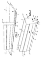
- Figure 1 illustrates an illustrative embodiment of a coating applicator 10 that may be used to apply a coating of material M to a work surface S of a work piece W.
- the applicator 10 may establish a reservoir that is configured to retain a liquid coating material via viscous retention and to dispense a bead of the liquid coating material via surface adhesion, cohesion, and gravity.
- the applicator 10 may be a sealant applicator to apply a chromated sealant to a trailing edge of an aircraft wing.
- the sealant may be an adhesive sealant that tends to adhere to the work surface S according to adhesive forces that are stronger than adhesive forces between the sealant and the applicator 10.
- the applicator 10 may include a rear outlet 12 through which the material M may flow.
- the applicator 10 also may include one or more lateral outlets 14 upstream of the rear outlet 12 to facilitate creation of a desired width of a bead of the material M.
- the applicator 10 may be moved along a longitudinal axis A, and/or the work piece W may be moved along the axis A.
- the material M couples to the work surface S according to adhesive forces therebetween, flows under its own weight due to gravity, and is pulled out of the applicator 10 during relative motion between the applicator 10 and the work piece W according to cohesive forces of or within the material M itself.
- work surface refers not only to aircraft wing applications, but also to aircraft fuselages, automobile bodies, watercraft hulls, windmill impellers, and any other suitable applications, and regardless of the particular type of material applied to the work surface.
- the term "material” may include sealant, paste, resin, oil, paint, or any other moderate to high viscosity fluid, for example, 500 to 15,000 poise @ ⁇ 50 degrees F and, more particularly, for instance, 1,000 to 4,000 poise @ ⁇ 50 degrees F.
- the applicator 10 includes side walls 16, 18 spaced laterally apart from one another, a front wall 20 coupled to and extending laterally between the side walls 16, 18, a rear wall 22 spaced apart longitudinally from the front wall 20 and coupled to and extending laterally between the side walls 16, 18.
- the front and rear walls 20, 22 may be straight, and the side walls 16, 18 may be offset, for example, to include lower portions 16a, 18a, upper portions 16b, 18b, and outwardly tapered portions 16c, 18c therebetween.
- the sidewalls 16, 18 may include laterally outwardly extending flanges 17, 19, for example, to facilitate applicator handling, storage, or the like.
- the walls 16, 18, 20, 22 of the applicator 10 may be integral with one another.
- the applicator 10 may be an integral, unitary, article of manufacture and may be produced by injection molding, additive manufacturing techniques, for instance, three-dimensional printing or stereo lithography, or in any other suitable manner.
- the applicator 10 may be composed of plastic, for example, acrylonitrile butadiene styrene (ABS). But those of ordinary skill in the art will recognize that the applicator 10 may be composed of metal constructed by welding, stamping, drawing, or the like, or may be composed of any other suitable material and constructed in any other suitable manner.
- the walls 16, 18, 20, 22 include corresponding top surfaces 24, 26, 28, 30 ( FIG. 2 ) and bottom surfaces 25, 27, 29, 31 ( FIG. 3 ).
- the top surfaces 24, 26, 28, 30 may be coplanar and may establish an open top or inlet of the applicator 10.
- the bottom surfaces 25, 27, 29 of the side and front walls 16, 18, 20 may be coplanar, and all bottom surfaces 25, 27, 29, 31 may establish a bottom opening of the applicator 10.
- the bottom opening may be in a first opening plane.
- the walls 16, 18, 20, 22 include corresponding exterior surfaces 32, 34, 36, 38, and correspondingly spaced apart interior surfaces 33, 35, 37, 39.
- the interior surfaces 33, 35, 37, 39 may contact the coating material, such that the walls 16, 18, 20, 22 establish a circumferentially complete reservoir to hold the coating material on the work surface for dispensing out of the rear outlet 12.
- the rear bottom surface 31 of the rear wall 18 extends from the rear exterior surface 38 and, more specifically, extends longitudinally between the rear exterior and interior surfaces 38, 39. As also shown in Figure 6 , the rear bottom surface 31 is spaced vertically or altitudinally away from the side bottom surfaces 25, 27 to establish the rear outlet 12.
- the rear bottom surface 31 may appear to be planar, as illustrated, or a narrow edge or line.
- the rear outlet 12 may be in communication with the bottom opening established by the front and/or side walls 16, 18, 20, and may be in a second opening plane disposed at a non-zero angle with respect to the first opening plane.
- the second opening plane may be perpendicular to the first opening plane as illustrated, but may be disposed at any other suitable angle.
- a rear bevel surface 40 extends from the rear bottom surface 31 in an inward direction and, more specifically, extends longitudinally and vertically between the rear bottom and interior surfaces 31, 39 to promote gradual compression of coating material toward the rear outlet 12. Accordingly, the coating material will be squeezed, instead of just sheared, before it exits the applicator 10 underneath the rear bottom surface 31. It was discovered that such material compression prior to exit results in good uniformity of bead thickness. Without the rear bevel surface 40, the applicator 10 tends to lay down a bead of coating material of unpredictable or non-uniform thickness.
- side bevel surfaces 42, 44 extend from side bottom surfaces 25, 27 in an inward direction and, more specifically, extend laterally and vertically between the side bottom and interior surfaces 25, 27, 33, 35 to further promote gradual squeezing of the coating material.
- the rear and side bevel surfaces 40, 42, 44 may be part of a continuous bevel surface that may extend greater than ninety angular degrees among the side and rear walls 16, 18, 22.
- the continuous bevel surface (40, 42, 44) extends over about 270 angular degrees (among the rear wall 22 and the adjacent side walls 16, 18).
- the rear and side bevel surfaces 40, 42, 44 may be filleted and, as such, may include fillets 46, 48.
- the bevel surfaces 40, 42, 44 may be flat, dished or incurvate, or of any other suitable shape.
- the bottom surfaces 25, 27 of the side walls 16, 18 are longitudinally tapered to include tapered bottom surfaces 50, 52 that are wider in locations relatively distal with respect to the rear wall 22 and narrower in locations relatively proximate with respect to the rear wall 22.
- the tapered bottom surfaces 50, 52 establish an open taper angle X of, for example, between 5 and 15 degrees, including all sub-ranges of angles and discrete angles therebetween. More particularly, the open taper angle X may be between 8 and 9 degrees, including all sub-ranges of angles and discrete angles therebetween.
- the lateral outlets 14 may be provided at least in portions of the side and rear walls 16, 18, 22 and may be in communication with the bottom opening.
- the lateral outlets 14 may include lateral outlet bottom surfaces 54, 56, which may extend laterally between the side exterior surfaces 32, 34 and the rear and side bevel surfaces 40, 42, 44.
- the lateral outlets 14 include forward facing surfaces 58, 60 in the rear wall 22 extending from the rear bottom surface 31 to the lateral outlet bottom surfaces 54, 56 and that may be disposed at a non-zero angle with respect to the longitudinal axis A of the coating applicator 10.
- the lateral outlets 14 also may include rearward facing surfaces 62, 64 that may extend vertically from the lateral outlet bottom surfaces 54, 56.
- the lateral outlets may be disposed in lateral opening planes different from the other opening planes of the bottom opening and the rear outlet 12, for example, at non-zero angles with respect to the first and second opening planes.
- the lateral opening planes may be parallel to one another and perpendicular to the first and second opening planes as illustrated, but may be disposed at any other suitable angle(s).
- the lateral outlet bottom surfaces 54, 56 may be spaced vertically from the rear bottom surface 31 in a direction away from the side bottom surfaces 25, 27.
- the illustrated example applicator 10 may include the following dimensions and specifications.
- the overall length of the applicator 10 may be 7.75 inches, the overall height of the applicator 10 may be 2.375 inches, and the overall width of the applicator 10 not including the flanges 17, 19 may be 1.72 inches.
- the width of the applicator 10 at the lower portions 16a, 18a of the sidewalls 16, 18 may be 0.87 inches, the thickness of the walls 16, 18, 20, 22 may be 0.125 inches, and, thus, an example width of a bead of the coating material may be about 0.62 inches.
- the length of the outlet features may be 1.50 inches, from the wide portion of the tapered bottom surfaces 50, 52 to the exterior surface 38 of the rear wall 22.
- the space between the bottom surface 31 of the rear wall 22 and the bottom surfaces 25, 27 of the side walls may be 0.032 inches, and the space between the bottom surfaces 54, 56 of the lateral outlets 14 and the bottom surfaces 25, 27 of the side walls 16, 18 may be 0.062 inches.
- the thickness of the bead of material M may be, for example, 0.007" to 0.045" on the work surface S.
- the viscosity of the example chromated sealant was about 1825 poise @ ⁇ 50 degrees F, but any other suitable viscosity material may be used.
- the applicator 10 may be an open container from top to bottom with no obstructions therebetween. It is noted that the tapered portions 16c, 18c of the sidewalls 16, 18 are not obstructions.
- a method of configuring a reservoir of a liquid coating applicator for viscous retention of a liquid coating material to be applied and further configuring the reservoir to dispense the liquid coating material via surface adhesion, cohesion, and gravity.
- the reservoir is configured to retain the liquid coating material via viscous retention before the applicator has been placed on a work surface, and to dispense the liquid coating material via surface adhesion, cohesion, and gravity when the applicator is supported on and being drawn across a work surface.
- the method further may include the following steps.
- Material may be contained in an applicator with a rear outlet so that the material flows toward the work surface under its own weight due to gravity and couples to the work surface according to adhesive forces between the material and the work surface.
- the applicator may be moved relative to the work surface so that the rear outlet trails along a work path and so that the material is pulled out of the applicator through the rear outlet according to cohesive forces of the material. Gradual compression of the material may be promoted in a vertical direction as the material is pulled from the applicator to the work surface through the outlet.
- the method also may include configuring the reservoir to promote gradual expansion of the material in a lateral direction as it is pulled from the applicator to the outlet, and/or facilitating lateral dispensing of the material upstream of the rear outlet.
- a product may be produced by the aforementioned method(s).
- a wing or a portion thereof may be produced by the aforementioned method(s).
Landscapes
- Coating Apparatus (AREA)
- Application Of Or Painting With Fluid Materials (AREA)
Abstract
Description
- The present disclosure relates generally to coating and, more particularly, to coating methods and products used to apply coatings to work surfaces.
- Manufacturing processes in many fields require extremely precise and consistent coatings, for instance, uniformly thick beads of material. For example, aircraft wing panels often require application of ribbon-shaped sealant beads. It is known to apply such beads by squirting sealant from a tube onto a work surface and then using a roller to smooth out the sealant to a desired thickness. But current bead application techniques may be too messy, may vary in quality significantly from worker to worker, may take too much time to accomplish, and wastes much costly material.
- In one embodiment, a coating applicator includes a liquid coating material reservoir configured to retain a liquid coating material via viscous retention and to dispense a liquid coating bead via surface adhesion, cohesion, and gravity.
- In another embodiment, there is presented a method of applying a bead of a liquid coating material to a work surface including:
- selecting a liquid coating material to be applied;
- configuring a reservoir of a liquid coating applicator for viscous retention of the liquid coating material;
- further configuring the reservoir to dispense the liquid coating material via surface adhesion, cohesion, and gravity;
- containing the liquid coating material in the applicator;
- supporting the applicator on a work surface such that the liquid coating material flows toward the work surface under its own weight due to gravity through a lower opening of the applicator and couples to the work surface according to adhesive forces between the liquid coating material and the work surface; and
- moving the applicator relative to the work surface so that a rear outlet of the applicator trails along a work path and so that the liquid coating material is pulled out of the applicator through the rear outlet according to cohesive forces of the liquid coating material.
- The invention includes a coating applicator comprising a liquid coating material reservoir configured to retain a liquid coating material via viscous retention and to dispense a liquid coating bead via surface adhesion, cohesion, and gravity.
- Optionally, the coating applicator comprises:
- side walls spaced laterally apart and having side bottom surfaces at least partially establishing a bottom opening in a first opening plane; and
- a rear wall coupled to and extending laterally between the side walls and having a rear bottom surface spaced vertically away from the side bottom surfaces to establish a rear outlet in a second opening plane and communication with the bottom opening.
- Optionally, the rear wall also includes:
- a rear exterior surface,
- a rear interior surface spaced longitudinally from the rear exterior surface,
- the rear bottom surface extending from the rear exterior surface, and extending longitudinally between the rear exterior and interior surfaces, and
- a rear bevel surface extending from the rear bottom surface, and extending longitudinally and vertically between the rear bottom and interior surfaces to promote gradual compression of material in a vertical direction as material is pulled out of the applicator toward a work surface through the rear outlet.
- Optionally, the side walls also have:
- side exterior surfaces,
- side interior surfaces spaced laterally from the side exterior surfaces, and
- side bevel surfaces extending from side bottom surfaces and extending laterally and vertically between the side bottom and interior surfaces to further promote gradual squeezing of material.
- Optionally, the rear and side bevel surfaces are part of a continuous bevel surface extending greater than ninety angular degrees among the rear and side walls.
- Optionally, the rear and side bevel surfaces are filleted.
- Optionally, the bottom surfaces of the side walls are longitudinally tapered, being wider in locations relatively distal with respect to the rear wall and being narrower in locations relatively proximate with respect to the rear wall.
- Optionally, the tapered bottom surfaces establish an open taper angle of 5 to 15 degrees.
- Optionally, the rear and side walls have lateral outlets in communication with the bottom opening and disposed in lateral opening planes different from the other opening planes and including lateral outlet bottom surfaces spaced vertically from the rear bottom surface in a direction away from the side bottom surfaces.
- Optionally, the lateral outlet bottom surfaces extend laterally between the side exterior surfaces and the rear and side bevel surfaces.
- Optionally, the lateral outlets include tapered surfaces in the rear wall extending from the rear bottom surface to the lateral outlet bottom surfaces and being disposed at a non-zero angle with respect to a longitudinal axis of the coating applicator.
- Optionally, the coating applicator further comprises a front wall coupled to and extending laterally between the side walls, spaced longitudinally from the rear wall, and having a front bottom surface at least partially establishing the bottom opening in the first opening plane, wherein the walls establish a circumferentially complete reservoir to hold material for dispensing out of the rear outlet.
- Optionally, the side walls include straight lower portions, outwardly tapered portions extending laterally outwardly and vertically from the straight lower portions, and straight upper portions extending vertically from the outwardly tapered portions, and wherein the front and rear walls are straight.
- Optionally, the front wall has a bottom surface that, together with the bottom surfaces of the side walls, establish the first opening plane for the bottom opening, and all of the walls include upper surfaces that together establish an open top.
- Optionally, no bottom wall connects the side walls and no wall extends longitudinally from the rear wall and laterally between the side walls over the rear outlet.
- The invention also includes a method of applying a bead of a liquid coating material to a work surface by
selecting a liquid coating material to be applied;
configuring a reservoir of a liquid coating applicator for viscous retention of the liquid coating material;
further configuring the reservoir to dispense the liquid coating material via surface adhesion, cohesion, and gravity;
containing the liquid coating material in the applicator;
supporting the applicator on a work surface such that the liquid coating material flows toward the work surface under its own weight due to gravity through a lower opening of the applicator and couples to the work surface according to adhesive forces between the liquid coating material and the work surface; and
moving the applicator relative to the work surface so that a rear outlet of the applicator trails along a work path and so that the liquid coating material is pulled out of the applicator through the rear outlet according to cohesive forces of the liquid coating material. - Optionally, the step of configuring a reservoir includes configuring the reservoir to promote gradual compression of the liquid coating material in a vertical direction as it is pulled from the applicator to the work surface through the rear outlet.
- Optionally, the step of configuring the reservoir also includes configuring the reservoir to promote gradual expansion of the material in a lateral direction as it is pulled from the applicator to the outlet.
- Optionally, the step of containing a liquid coating material in the applicator includes filling the applicator with the liquid coating material before the step of supporting the applicator on a work surface, wherein the applicator retains the liquid coating material in the reservoir.
- The invention also includes a product produced by the disclosed method.
- These and other features and advantages will become apparent to those skilled in the art in connection with the following detailed description and drawings of one or more embodiments of the invention, in which:
-
Figure 1 is a fragmentary view of an example embodiment of a coating applicator being used to apply material on a work surface of a work piece; -
Figure 2 is a top rear view of the coating applicator ofFigure 1 ; -
Figure 3 is a bottom rear view of the coating applicator ofFigure 1 ; -
Figure 4 is an enlarged, fragmentary, top view of a front portion of the coating applicator ofFigure 1 ; -
Figure 5 is an enlarged, fragmentary, bottom view of a rear portion of the coating applicator ofFigure 1 ; -
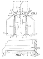
Figure 6 is an enlarged, fragmentary, cross-sectional view of a rear portion of the coating applicator ofFigure 1 , taken along line 6-6 ofFigure 2 ; -
Figure 7 is an enlarged, fragmentary, side view of a rear portion of the coating applicator ofFigure 1 ; and -
Figure 8 is an enlarged, fragmentary, bottom rear view of the coating applicator ofFigure 1 . -
Figure 1 illustrates an illustrative embodiment of acoating applicator 10 that may be used to apply a coating of material M to a work surface S of a work piece W. Theapplicator 10 may establish a reservoir that is configured to retain a liquid coating material via viscous retention and to dispense a bead of the liquid coating material via surface adhesion, cohesion, and gravity. For example, theapplicator 10 may be a sealant applicator to apply a chromated sealant to a trailing edge of an aircraft wing. The sealant may be an adhesive sealant that tends to adhere to the work surface S according to adhesive forces that are stronger than adhesive forces between the sealant and theapplicator 10. Theapplicator 10 may include arear outlet 12 through which the material M may flow. Theapplicator 10 also may include one or morelateral outlets 14 upstream of therear outlet 12 to facilitate creation of a desired width of a bead of the material M. Theapplicator 10 may be moved along a longitudinal axis A, and/or the work piece W may be moved along the axis A. In any event, the material M couples to the work surface S according to adhesive forces therebetween, flows under its own weight due to gravity, and is pulled out of theapplicator 10 during relative motion between theapplicator 10 and the work piece W according to cohesive forces of or within the material M itself. - The example embodiment is described and illustrated with reference to its use for applying an adhesive sealant in an aircraft wing environment. However, it will be appreciated as the description proceeds that the present disclosure is useful in many different applications and may be implemented in many other embodiments. In this regard, and as used herein and in the claims, it will be understood that the term "work surface" refers not only to aircraft wing applications, but also to aircraft fuselages, automobile bodies, watercraft hulls, windmill impellers, and any other suitable applications, and regardless of the particular type of material applied to the work surface. Also, as used herein and in the claims, the term "material" may include sealant, paste, resin, oil, paint, or any other moderate to high viscosity fluid, for example, 500 to 15,000 poise @ ∼50 degrees F and, more particularly, for instance, 1,000 to 4,000 poise @ ∼50 degrees F.
- With reference to
Figures 2 and3 , theapplicator 10 includesside walls front wall 20 coupled to and extending laterally between theside walls rear wall 22 spaced apart longitudinally from thefront wall 20 and coupled to and extending laterally between theside walls rear walls side walls upper portions 16b, 18b, and outwardlytapered portions 16c, 18c therebetween. Also, thesidewalls flanges walls applicator 10 may be integral with one another. - In fact, the
applicator 10 may be an integral, unitary, article of manufacture and may be produced by injection molding, additive manufacturing techniques, for instance, three-dimensional printing or stereo lithography, or in any other suitable manner. Theapplicator 10 may be composed of plastic, for example, acrylonitrile butadiene styrene (ABS). But those of ordinary skill in the art will recognize that theapplicator 10 may be composed of metal constructed by welding, stamping, drawing, or the like, or may be composed of any other suitable material and constructed in any other suitable manner. - In any case, the
walls top surfaces FIG. 2 ) and bottom surfaces 25, 27, 29, 31 (FIG. 3 ). The top surfaces 24, 26, 28, 30 may be coplanar and may establish an open top or inlet of theapplicator 10. The bottom surfaces 25, 27, 29 of the side andfront walls bottom surfaces applicator 10. The bottom opening may be in a first opening plane. - Moreover, and referring now to
Figures 4 and/or 5, thewalls interior surfaces walls rear outlet 12. - Referring to
Figure 5 , therear bottom surface 31 of therear wall 18 extends from therear exterior surface 38 and, more specifically, extends longitudinally between the rear exterior andinterior surfaces Figure 6 , therear bottom surface 31 is spaced vertically or altitudinally away from the side bottom surfaces 25, 27 to establish therear outlet 12. Therear bottom surface 31 may appear to be planar, as illustrated, or a narrow edge or line. Therear outlet 12 may be in communication with the bottom opening established by the front and/orside walls - Still referring to
Figure 5 , arear bevel surface 40 extends from therear bottom surface 31 in an inward direction and, more specifically, extends longitudinally and vertically between the rear bottom andinterior surfaces rear outlet 12. Accordingly, the coating material will be squeezed, instead of just sheared, before it exits theapplicator 10 underneath therear bottom surface 31. It was discovered that such material compression prior to exit results in good uniformity of bead thickness. Without therear bevel surface 40, theapplicator 10 tends to lay down a bead of coating material of unpredictable or non-uniform thickness. - Similarly, side bevel surfaces 42, 44 extend from side bottom surfaces 25, 27 in an inward direction and, more specifically, extend laterally and vertically between the side bottom and
interior surfaces rear walls rear wall 22 and theadjacent side walls 16, 18). The rear and side bevel surfaces 40, 42, 44 may be filleted and, as such, may includefillets - Also, the bottom surfaces 25, 27 of the
side walls rear wall 22 and narrower in locations relatively proximate with respect to therear wall 22. The tapered bottom surfaces 50, 52 establish an open taper angle X of, for example, between 5 and 15 degrees, including all sub-ranges of angles and discrete angles therebetween. More particularly, the open taper angle X may be between 8 and 9 degrees, including all sub-ranges of angles and discrete angles therebetween. - The
lateral outlets 14 may be provided at least in portions of the side andrear walls lateral outlets 14 may include lateral outlet bottom surfaces 54, 56, which may extend laterally between the side exterior surfaces 32, 34 and the rear and side bevel surfaces 40, 42, 44. Thelateral outlets 14 include forward facingsurfaces rear wall 22 extending from therear bottom surface 31 to the lateral outlet bottom surfaces 54, 56 and that may be disposed at a non-zero angle with respect to the longitudinal axis A of thecoating applicator 10. Thelateral outlets 14 also may include rearward facingsurfaces rear outlet 12, for example, at non-zero angles with respect to the first and second opening planes. For example, the lateral opening planes may be parallel to one another and perpendicular to the first and second opening planes as illustrated, but may be disposed at any other suitable angle(s). - With reference to
Figures 6 and7 , the lateral outlet bottom surfaces 54, 56 may be spaced vertically from therear bottom surface 31 in a direction away from the side bottom surfaces 25, 27. - With reference to
Figures 1 and 2 , the illustratedexample applicator 10 may include the following dimensions and specifications. The overall length of theapplicator 10 may be 7.75 inches, the overall height of theapplicator 10 may be 2.375 inches, and the overall width of theapplicator 10 not including theflanges applicator 10 at the lower portions 16a, 18a of thesidewalls walls exterior surface 38 of therear wall 22. The space between thebottom surface 31 of therear wall 22 and the bottom surfaces 25, 27 of the side walls may be 0.032 inches, and the space between the bottom surfaces 54, 56 of thelateral outlets 14 and the bottom surfaces 25, 27 of theside walls - In the illustrated embodiment, there is no bottom wall that connects the
side walls rear wall 22 and laterally between theside walls rear outlet 12. Rather, theapplicator 10 may be an open container from top to bottom with no obstructions therebetween. It is noted that the taperedportions 16c, 18c of thesidewalls - According to another embodiment, there is presented a method of configuring a reservoir of a liquid coating applicator for viscous retention of a liquid coating material to be applied, and further configuring the reservoir to dispense the liquid coating material via surface adhesion, cohesion, and gravity. In other words, according to this method, the reservoir is configured to retain the liquid coating material via viscous retention before the applicator has been placed on a work surface, and to dispense the liquid coating material via surface adhesion, cohesion, and gravity when the applicator is supported on and being drawn across a work surface. The method further may include the following steps. Material may be contained in an applicator with a rear outlet so that the material flows toward the work surface under its own weight due to gravity and couples to the work surface according to adhesive forces between the material and the work surface. The applicator may be moved relative to the work surface so that the rear outlet trails along a work path and so that the material is pulled out of the applicator through the rear outlet according to cohesive forces of the material. Gradual compression of the material may be promoted in a vertical direction as the material is pulled from the applicator to the work surface through the outlet.
- The method also may include configuring the reservoir to promote gradual expansion of the material in a lateral direction as it is pulled from the applicator to the outlet, and/or facilitating lateral dispensing of the material upstream of the rear outlet.
- A product may be produced by the aforementioned method(s). For example, a wing or a portion thereof may be produced by the aforementioned method(s).
- This description, rather than describing limitations of an invention, only illustrates example embodiments of the invention recited in the claims. The language of this description is therefore exclusively descriptive and non-limiting. Obviously, it's possible to modify this invention from what the description teaches. Within the scope of the claims, one may practice the invention other than as described above.
Claims (15)
- A coating applicator comprising a liquid coating material reservoir configured to retain a liquid coating material via viscous retention and to dispense a liquid coating bead via surface adhesion, cohesion, and gravity.
- The coating applicator of claim 1, comprising:side walls spaced laterally apart and having side bottom surfaces at least partially establishing a bottom opening in a first opening plane; anda rear wall coupled to and extending laterally between the side walls and having a rear bottom surface spaced vertically away from the side bottom surfaces to establish a rear outlet in a second opening plane and communication with the bottom opening.
- The coating applicator of claim 2, wherein the rear wall also includes:a rear exterior surface,a rear interior surface spaced longitudinally from the rear exterior surface,the rear bottom surface extending from the rear exterior surface, and extending longitudinally between the rear exterior and interior surfaces, anda rear bevel surface extending from the rear bottom surface, and extending longitudinally and vertically between the rear bottom and interior surfaces to promote gradual compression of material in a vertical direction as material is pulled out of the applicator toward a work surface through the rear outlet.
- The coating applicator of claim 2 or claim 3, wherein the side walls also have:side exterior surfaces,side interior surfaces spaced laterally from the side exterior surfaces, andside bevel surfaces extending from side bottom surfaces and extending laterally and vertically between the side bottom and interior surfaces to further promote gradual squeezing of material.
- The coating applicator of claim 4 wherein the rear and side bevel surfaces are part of a continuous bevel surface extending greater than ninety angular degrees among the rear and side walls.
- The coating applicator of claim 4 or claim 5, wherein the rear and side bevel surfaces are filleted.
- The coating applicator of any one of claims 2 to 6 wherein the bottom surfaces of the side walls are longitudinally tapered, being wider in locations relatively distal with respect to the rear wall and being narrower in locations relatively proximate with respect to the rear wall;
optionally wherein the tapered bottom surfaces establish an open taper angle of 5 to 15 degrees. - The coating applicator of any one of claims 2 to 7, wherein the rear and side walls have lateral outlets in communication with the bottom opening and disposed in lateral opening planes different from the other opening planes and including lateral outlet bottom surfaces spaced vertically from the rear bottom surface in a direction away from the side bottom surfaces;
optionally wherein the lateral outlet bottom surfaces extend laterally between the side exterior surfaces and the rear and side bevel surfaces;
optionally wherein the lateral outlets include tapered surfaces in the rear wall extending from the rear bottom surface to the lateral outlet bottom surfaces and being disposed at a non-zero angle with respect to a longitudinal axis of the coating applicator. - The coating applicator of any one of claims 2 to 8, further comprising a front wall coupled to and extending laterally between the side walls, spaced longitudinally from the rear wall, and having a front bottom surface at least partially establishing the bottom opening in the first opening plane, wherein the walls establish a circumferentially complete reservoir to hold material for dispensing out of the rear outlet;
optionally wherein the side walls include straight lower portions, outwardly tapered portions extending laterally outwardly and vertically from the straight lower portions, and straight upper portions extending vertically from the outwardly tapered portions, and wherein the front and rear walls are straight;
optionally wherein the front wall has a bottom surface that, together with the bottom surfaces of the side walls, establish the first opening plane for the bottom opening, and all of the walls include upper surfaces that together establish an open top. - The coating applicator of any one of claims 2 to 9, further wherein no bottom wall connects the side walls and no wall extends longitudinally from the rear wall and laterally between the side walls over the rear outlet.
- A method of applying a bead of a liquid coating material to a work surface by selecting a liquid coating material to be applied;
configuring a reservoir of a liquid coating applicator for viscous retention of the liquid coating material;
further configuring the reservoir to dispense the liquid coating material via surface adhesion, cohesion, and gravity;
containing the liquid coating material in the applicator;
supporting the applicator on a work surface such that the liquid coating material flows toward the work surface under its own weight due to gravity through a lower opening of the applicator and couples to the work surface according to adhesive forces between the liquid coating material and the work surface; and
moving the applicator relative to the work surface so that a rear outlet of the applicator trails along a work path and so that the liquid coating material is pulled out of the applicator through the rear outlet according to cohesive forces of the liquid coating material. - The method of claim 11, in which the step of configuring a reservoir includes configuring the reservoir to promote gradual compression of the liquid coating material in a vertical direction as it is pulled from the applicator to the work surface through the rear outlet.
- The method of claim 11 or claim 12, in which:the step of configuring the reservoir also includes configuring the reservoir to promote gradual expansion of the material in a lateral direction as it is pulled from the applicator to the outlet.
- The method of claim 11, 12 or 13, in which the step of containing a liquid coating material in the applicator includes filling the applicator with the liquid coating material before the step of supporting the applicator on a work surface, wherein the applicator retains the liquid coating material in the reservoir.
- A product produced by the method of any one of claims 11 to 14.
Applications Claiming Priority (1)
| Application Number | Priority Date | Filing Date | Title |
|---|---|---|---|
| US13/832,329 US9682401B2 (en) | 2013-03-15 | 2013-03-15 | Coating application |
Publications (2)
| Publication Number | Publication Date |
|---|---|
| EP2777825A1 true EP2777825A1 (en) | 2014-09-17 |
| EP2777825B1 EP2777825B1 (en) | 2017-07-19 |
Family
ID=50343594
Family Applications (1)
| Application Number | Title | Priority Date | Filing Date |
|---|---|---|---|
| EP14159559.5A Active EP2777825B1 (en) | 2013-03-15 | 2014-03-13 | Coating application |
Country Status (2)
| Country | Link |
|---|---|
| US (1) | US9682401B2 (en) |
| EP (1) | EP2777825B1 (en) |
Cited By (1)
| Publication number | Priority date | Publication date | Assignee | Title |
|---|---|---|---|---|
| EP3378571A1 (en) * | 2017-03-23 | 2018-09-26 | LM WP Patent Holding A/S | A dispenser device for applying structural adhesive and a method using such a dispenser device |
Families Citing this family (1)
| Publication number | Priority date | Publication date | Assignee | Title |
|---|---|---|---|---|
| WO2020233760A1 (en) * | 2019-05-21 | 2020-11-26 | Vestas Wind Systems A/S | An adhesive deposition tool for applying structural adhesive to a wind turbine blade component |
Citations (5)
| Publication number | Priority date | Publication date | Assignee | Title |
|---|---|---|---|---|
| US1158460A (en) * | 1915-04-08 | 1915-11-02 | Castleman David Doll | Mortar-spreader. |
| GB602084A (en) * | 1945-12-18 | 1948-05-19 | John William Laing | Method and means for facilitating the laying of bricks |
| GB2047127A (en) * | 1979-04-09 | 1980-11-26 | Grace W R & Co | Dispensing of photopolymer |
| US4518634A (en) * | 1983-05-12 | 1985-05-21 | International Business Machines Corporation | Method and apparatus for coating magnetic recording media |
| US6120603A (en) * | 1998-07-01 | 2000-09-19 | Face International Corp. | Adhesive viscous liquid screed |
Family Cites Families (7)
| Publication number | Priority date | Publication date | Assignee | Title |
|---|---|---|---|---|
| US2108952A (en) | 1937-07-14 | 1938-02-22 | Urban John | Striping tool |
| US2643408A (en) | 1950-01-05 | 1953-06-30 | Decker Howard William | Resilient reservoir with applicator closure |
| US4006049A (en) * | 1975-05-19 | 1977-02-01 | Gardner David L | Pipe coating apparatus |
| US4451164A (en) * | 1980-07-14 | 1984-05-29 | Roberts Jr James E | Dispensing container |
| AT386762B (en) * | 1985-05-08 | 1988-10-10 | Zimmer Johannes | METHOD AND DEVICE FOR IMPREGNATING AND / OR COATING APPLICATION ON A TRACK OF GOODS |
| US5489046A (en) * | 1990-09-18 | 1996-02-06 | Wickham; Sandy J. | Squeezable dispenser with a recessed bottom spout |
| US5277511A (en) | 1991-09-27 | 1994-01-11 | Stockton Lonnie J | Flowable material spreader |
-
2013
- 2013-03-15 US US13/832,329 patent/US9682401B2/en active Active
-
2014
- 2014-03-13 EP EP14159559.5A patent/EP2777825B1/en active Active
Patent Citations (5)
| Publication number | Priority date | Publication date | Assignee | Title |
|---|---|---|---|---|
| US1158460A (en) * | 1915-04-08 | 1915-11-02 | Castleman David Doll | Mortar-spreader. |
| GB602084A (en) * | 1945-12-18 | 1948-05-19 | John William Laing | Method and means for facilitating the laying of bricks |
| GB2047127A (en) * | 1979-04-09 | 1980-11-26 | Grace W R & Co | Dispensing of photopolymer |
| US4518634A (en) * | 1983-05-12 | 1985-05-21 | International Business Machines Corporation | Method and apparatus for coating magnetic recording media |
| US6120603A (en) * | 1998-07-01 | 2000-09-19 | Face International Corp. | Adhesive viscous liquid screed |
Cited By (3)
| Publication number | Priority date | Publication date | Assignee | Title |
|---|---|---|---|---|
| EP3378571A1 (en) * | 2017-03-23 | 2018-09-26 | LM WP Patent Holding A/S | A dispenser device for applying structural adhesive and a method using such a dispenser device |
| WO2018172457A1 (en) * | 2017-03-23 | 2018-09-27 | Lm Wind Power International Technology Ii Aps | A dispenser device for applying structural adhesive and a method using such a dispenser device |
| US11819874B2 (en) | 2017-03-23 | 2023-11-21 | Lm Wp Patent Holding A/S | Dispenser device for applying structural adhesive and a method using such a dispenser device |
Also Published As
| Publication number | Publication date |
|---|---|
| US20140261081A1 (en) | 2014-09-18 |
| EP2777825B1 (en) | 2017-07-19 |
| US9682401B2 (en) | 2017-06-20 |
Similar Documents
| Publication | Publication Date | Title |
|---|---|---|
| US20090152307A1 (en) | Non-cylindrical bead for caulking tube | |
| EP1857189B1 (en) | Application apparatus, application method and method for manufacturing web having coating film | |
| EP3268136B1 (en) | Nozzle, method and use of the nozzle for dispensing resin onto a panel edge | |
| US9943876B2 (en) | Flow restrictor | |
| EP2777825B1 (en) | Coating application | |
| CN105263637A (en) | Nozzle for silicon container | |
| WO2012150471A1 (en) | Bead forming tip for caulking guns | |
| JP2008246476A (en) | Applicator nozzle for applying glass sealant and method of using the applicator nozzle | |
| US12194493B2 (en) | Method of applying filament adhesive | |
| US9855582B2 (en) | Viscous fluid applicator | |
| WO2014064441A1 (en) | Tool for shaping sealant | |
| CN105689176B (en) | Field application instrument and the painting device for possessing the instrument | |
| CN102794988B (en) | Coating device | |
| EP2512697B1 (en) | Method for removing excess adhesive | |
| CN112191454A (en) | Composite material edge gluing and sealing device and application method thereof | |
| CN218078725U (en) | Coating machine capable of realizing continuous and synchronous blade coating | |
| JPH0833861A (en) | Machine for coating end edge of building board | |
| US11612908B2 (en) | Nozzle having quadrilateral outlet for viscous material distribution | |
| JP5255428B2 (en) | How to paint building boards | |
| GB2487778A (en) | Nozzle for delivering a flowable substance | |
| JP2009007863A (en) | Adhesive applying equipment for baseboard construction | |
| EP3717140B1 (en) | Device and method for melting a hot-melt adhesive | |
| JP5312014B2 (en) | Building board painting equipment | |
| EP3858754B1 (en) | Method and package for reducing adhesions within filled containers | |
| JP2016043312A (en) | Method and apparatus for applying high-viscosity material, and high-viscosity material application |
Legal Events
| Date | Code | Title | Description |
|---|---|---|---|
| 17P | Request for examination filed |
Effective date: 20140313 |
|
| AK | Designated contracting states |
Kind code of ref document: A1 Designated state(s): AL AT BE BG CH CY CZ DE DK EE ES FI FR GB GR HR HU IE IS IT LI LT LU LV MC MK MT NL NO PL PT RO RS SE SI SK SM TR |
|
| AX | Request for extension of the european patent |
Extension state: BA ME |
|
| PUAI | Public reference made under article 153(3) epc to a published international application that has entered the european phase |
Free format text: ORIGINAL CODE: 0009012 |
|
| R17P | Request for examination filed (corrected) |
Effective date: 20150317 |
|
| RBV | Designated contracting states (corrected) |
Designated state(s): AL AT BE BG CH CY CZ DE DK EE ES FI FR GB GR HR HU IE IS IT LI LT LU LV MC MK MT NL NO PL PT RO RS SE SI SK SM TR |
|
| GRAP | Despatch of communication of intention to grant a patent |
Free format text: ORIGINAL CODE: EPIDOSNIGR1 |
|
| STAA | Information on the status of an ep patent application or granted ep patent |
Free format text: STATUS: GRANT OF PATENT IS INTENDED |
|
| INTG | Intention to grant announced |
Effective date: 20170315 |
|
| GRAS | Grant fee paid |
Free format text: ORIGINAL CODE: EPIDOSNIGR3 |
|
| GRAA | (expected) grant |
Free format text: ORIGINAL CODE: 0009210 |
|
| STAA | Information on the status of an ep patent application or granted ep patent |
Free format text: STATUS: THE PATENT HAS BEEN GRANTED |
|
| AK | Designated contracting states |
Kind code of ref document: B1 Designated state(s): AL AT BE BG CH CY CZ DE DK EE ES FI FR GB GR HR HU IE IS IT LI LT LU LV MC MK MT NL NO PL PT RO RS SE SI SK SM TR |
|
| REG | Reference to a national code |
Ref country code: GB Ref legal event code: FG4D |
|
| REG | Reference to a national code |
Ref country code: CH Ref legal event code: EP |
|
| REG | Reference to a national code |
Ref country code: IE Ref legal event code: FG4D |
|
| REG | Reference to a national code |
Ref country code: AT Ref legal event code: REF Ref document number: 909876 Country of ref document: AT Kind code of ref document: T Effective date: 20170815 |
|
| REG | Reference to a national code |
Ref country code: DE Ref legal event code: R096 Ref document number: 602014011858 Country of ref document: DE |
|
| REG | Reference to a national code |
Ref country code: NL Ref legal event code: MP Effective date: 20170719 |
|
| REG | Reference to a national code |
Ref country code: LT Ref legal event code: MG4D |
|
| REG | Reference to a national code |
Ref country code: AT Ref legal event code: MK05 Ref document number: 909876 Country of ref document: AT Kind code of ref document: T Effective date: 20170719 |
|
| PG25 | Lapsed in a contracting state [announced via postgrant information from national office to epo] |
Ref country code: AT Free format text: LAPSE BECAUSE OF FAILURE TO SUBMIT A TRANSLATION OF THE DESCRIPTION OR TO PAY THE FEE WITHIN THE PRESCRIBED TIME-LIMIT Effective date: 20170719 Ref country code: NO Free format text: LAPSE BECAUSE OF FAILURE TO SUBMIT A TRANSLATION OF THE DESCRIPTION OR TO PAY THE FEE WITHIN THE PRESCRIBED TIME-LIMIT Effective date: 20171019 Ref country code: FI Free format text: LAPSE BECAUSE OF FAILURE TO SUBMIT A TRANSLATION OF THE DESCRIPTION OR TO PAY THE FEE WITHIN THE PRESCRIBED TIME-LIMIT Effective date: 20170719 Ref country code: LT Free format text: LAPSE BECAUSE OF FAILURE TO SUBMIT A TRANSLATION OF THE DESCRIPTION OR TO PAY THE FEE WITHIN THE PRESCRIBED TIME-LIMIT Effective date: 20170719 Ref country code: NL Free format text: LAPSE BECAUSE OF FAILURE TO SUBMIT A TRANSLATION OF THE DESCRIPTION OR TO PAY THE FEE WITHIN THE PRESCRIBED TIME-LIMIT Effective date: 20170719 Ref country code: SE Free format text: LAPSE BECAUSE OF FAILURE TO SUBMIT A TRANSLATION OF THE DESCRIPTION OR TO PAY THE FEE WITHIN THE PRESCRIBED TIME-LIMIT Effective date: 20170719 Ref country code: HR Free format text: LAPSE BECAUSE OF FAILURE TO SUBMIT A TRANSLATION OF THE DESCRIPTION OR TO PAY THE FEE WITHIN THE PRESCRIBED TIME-LIMIT Effective date: 20170719 |
|
| PG25 | Lapsed in a contracting state [announced via postgrant information from national office to epo] |
Ref country code: IS Free format text: LAPSE BECAUSE OF FAILURE TO SUBMIT A TRANSLATION OF THE DESCRIPTION OR TO PAY THE FEE WITHIN THE PRESCRIBED TIME-LIMIT Effective date: 20171119 Ref country code: BG Free format text: LAPSE BECAUSE OF FAILURE TO SUBMIT A TRANSLATION OF THE DESCRIPTION OR TO PAY THE FEE WITHIN THE PRESCRIBED TIME-LIMIT Effective date: 20171019 Ref country code: RS Free format text: LAPSE BECAUSE OF FAILURE TO SUBMIT A TRANSLATION OF THE DESCRIPTION OR TO PAY THE FEE WITHIN THE PRESCRIBED TIME-LIMIT Effective date: 20170719 Ref country code: LV Free format text: LAPSE BECAUSE OF FAILURE TO SUBMIT A TRANSLATION OF THE DESCRIPTION OR TO PAY THE FEE WITHIN THE PRESCRIBED TIME-LIMIT Effective date: 20170719 Ref country code: GR Free format text: LAPSE BECAUSE OF FAILURE TO SUBMIT A TRANSLATION OF THE DESCRIPTION OR TO PAY THE FEE WITHIN THE PRESCRIBED TIME-LIMIT Effective date: 20171020 Ref country code: ES Free format text: LAPSE BECAUSE OF FAILURE TO SUBMIT A TRANSLATION OF THE DESCRIPTION OR TO PAY THE FEE WITHIN THE PRESCRIBED TIME-LIMIT Effective date: 20170719 Ref country code: PL Free format text: LAPSE BECAUSE OF FAILURE TO SUBMIT A TRANSLATION OF THE DESCRIPTION OR TO PAY THE FEE WITHIN THE PRESCRIBED TIME-LIMIT Effective date: 20170719 |
|
| REG | Reference to a national code |
Ref country code: FR Ref legal event code: PLFP Year of fee payment: 5 |
|
| REG | Reference to a national code |
Ref country code: DE Ref legal event code: R097 Ref document number: 602014011858 Country of ref document: DE |
|
| PG25 | Lapsed in a contracting state [announced via postgrant information from national office to epo] |
Ref country code: DK Free format text: LAPSE BECAUSE OF FAILURE TO SUBMIT A TRANSLATION OF THE DESCRIPTION OR TO PAY THE FEE WITHIN THE PRESCRIBED TIME-LIMIT Effective date: 20170719 Ref country code: RO Free format text: LAPSE BECAUSE OF FAILURE TO SUBMIT A TRANSLATION OF THE DESCRIPTION OR TO PAY THE FEE WITHIN THE PRESCRIBED TIME-LIMIT Effective date: 20170719 Ref country code: CZ Free format text: LAPSE BECAUSE OF FAILURE TO SUBMIT A TRANSLATION OF THE DESCRIPTION OR TO PAY THE FEE WITHIN THE PRESCRIBED TIME-LIMIT Effective date: 20170719 |
|
| PLBE | No opposition filed within time limit |
Free format text: ORIGINAL CODE: 0009261 |
|
| STAA | Information on the status of an ep patent application or granted ep patent |
Free format text: STATUS: NO OPPOSITION FILED WITHIN TIME LIMIT |
|
| PG25 | Lapsed in a contracting state [announced via postgrant information from national office to epo] |
Ref country code: EE Free format text: LAPSE BECAUSE OF FAILURE TO SUBMIT A TRANSLATION OF THE DESCRIPTION OR TO PAY THE FEE WITHIN THE PRESCRIBED TIME-LIMIT Effective date: 20170719 Ref country code: SM Free format text: LAPSE BECAUSE OF FAILURE TO SUBMIT A TRANSLATION OF THE DESCRIPTION OR TO PAY THE FEE WITHIN THE PRESCRIBED TIME-LIMIT Effective date: 20170719 Ref country code: SK Free format text: LAPSE BECAUSE OF FAILURE TO SUBMIT A TRANSLATION OF THE DESCRIPTION OR TO PAY THE FEE WITHIN THE PRESCRIBED TIME-LIMIT Effective date: 20170719 |
|
| 26N | No opposition filed |
Effective date: 20180420 |
|
| PG25 | Lapsed in a contracting state [announced via postgrant information from national office to epo] |
Ref country code: SI Free format text: LAPSE BECAUSE OF FAILURE TO SUBMIT A TRANSLATION OF THE DESCRIPTION OR TO PAY THE FEE WITHIN THE PRESCRIBED TIME-LIMIT Effective date: 20170719 |
|
| REG | Reference to a national code |
Ref country code: CH Ref legal event code: PL |
|
| PG25 | Lapsed in a contracting state [announced via postgrant information from national office to epo] |
Ref country code: MC Free format text: LAPSE BECAUSE OF FAILURE TO SUBMIT A TRANSLATION OF THE DESCRIPTION OR TO PAY THE FEE WITHIN THE PRESCRIBED TIME-LIMIT Effective date: 20170719 |
|
| REG | Reference to a national code |
Ref country code: BE Ref legal event code: MM Effective date: 20180331 |
|
| REG | Reference to a national code |
Ref country code: IE Ref legal event code: MM4A |
|
| PG25 | Lapsed in a contracting state [announced via postgrant information from national office to epo] |
Ref country code: LU Free format text: LAPSE BECAUSE OF NON-PAYMENT OF DUE FEES Effective date: 20180313 |
|
| PG25 | Lapsed in a contracting state [announced via postgrant information from national office to epo] |
Ref country code: IE Free format text: LAPSE BECAUSE OF NON-PAYMENT OF DUE FEES Effective date: 20180313 |
|
| PG25 | Lapsed in a contracting state [announced via postgrant information from national office to epo] |
Ref country code: BE Free format text: LAPSE BECAUSE OF NON-PAYMENT OF DUE FEES Effective date: 20180331 Ref country code: LI Free format text: LAPSE BECAUSE OF NON-PAYMENT OF DUE FEES Effective date: 20180331 Ref country code: CH Free format text: LAPSE BECAUSE OF NON-PAYMENT OF DUE FEES Effective date: 20180331 |
|
| PG25 | Lapsed in a contracting state [announced via postgrant information from national office to epo] |
Ref country code: MT Free format text: LAPSE BECAUSE OF NON-PAYMENT OF DUE FEES Effective date: 20180313 |
|
| PG25 | Lapsed in a contracting state [announced via postgrant information from national office to epo] |
Ref country code: TR Free format text: LAPSE BECAUSE OF FAILURE TO SUBMIT A TRANSLATION OF THE DESCRIPTION OR TO PAY THE FEE WITHIN THE PRESCRIBED TIME-LIMIT Effective date: 20170719 |
|
| PG25 | Lapsed in a contracting state [announced via postgrant information from national office to epo] |
Ref country code: HU Free format text: LAPSE BECAUSE OF FAILURE TO SUBMIT A TRANSLATION OF THE DESCRIPTION OR TO PAY THE FEE WITHIN THE PRESCRIBED TIME-LIMIT; INVALID AB INITIO Effective date: 20140313 Ref country code: PT Free format text: LAPSE BECAUSE OF FAILURE TO SUBMIT A TRANSLATION OF THE DESCRIPTION OR TO PAY THE FEE WITHIN THE PRESCRIBED TIME-LIMIT Effective date: 20170719 |
|
| PG25 | Lapsed in a contracting state [announced via postgrant information from national office to epo] |
Ref country code: MK Free format text: LAPSE BECAUSE OF NON-PAYMENT OF DUE FEES Effective date: 20170719 Ref country code: CY Free format text: LAPSE BECAUSE OF FAILURE TO SUBMIT A TRANSLATION OF THE DESCRIPTION OR TO PAY THE FEE WITHIN THE PRESCRIBED TIME-LIMIT Effective date: 20170719 |
|
| PG25 | Lapsed in a contracting state [announced via postgrant information from national office to epo] |
Ref country code: AL Free format text: LAPSE BECAUSE OF FAILURE TO SUBMIT A TRANSLATION OF THE DESCRIPTION OR TO PAY THE FEE WITHIN THE PRESCRIBED TIME-LIMIT Effective date: 20170719 |
|
| P01 | Opt-out of the competence of the unified patent court (upc) registered |
Effective date: 20230515 |
|
| PGFP | Annual fee paid to national office [announced via postgrant information from national office to epo] |
Ref country code: GB Payment date: 20260327 Year of fee payment: 13 |
|
| PGFP | Annual fee paid to national office [announced via postgrant information from national office to epo] |
Ref country code: DE Payment date: 20260327 Year of fee payment: 13 |
|
| PGFP | Annual fee paid to national office [announced via postgrant information from national office to epo] |
Ref country code: IT Payment date: 20260319 Year of fee payment: 13 |
|
| PGFP | Annual fee paid to national office [announced via postgrant information from national office to epo] |
Ref country code: FR Payment date: 20260325 Year of fee payment: 13 |