EP2777754A1 - Automated frangible cannula breaker - Google Patents
Automated frangible cannula breaker Download PDFInfo
- Publication number
- EP2777754A1 EP2777754A1 EP20130192157 EP13192157A EP2777754A1 EP 2777754 A1 EP2777754 A1 EP 2777754A1 EP 20130192157 EP20130192157 EP 20130192157 EP 13192157 A EP13192157 A EP 13192157A EP 2777754 A1 EP2777754 A1 EP 2777754A1
- Authority
- EP
- European Patent Office
- Prior art keywords
- cannula
- station
- frangible
- flow path
- relative
- Prior art date
- Legal status (The legal status is an assumption and is not a legal conclusion. Google has not performed a legal analysis and makes no representation as to the accuracy of the status listed.)
- Granted
Links
- 238000005452 bending Methods 0.000 claims abstract description 20
- 238000000034 method Methods 0.000 claims abstract description 16
- 210000004369 blood Anatomy 0.000 claims description 25
- 239000008280 blood Substances 0.000 claims description 25
- 230000005540 biological transmission Effects 0.000 claims description 3
- 239000012530 fluid Substances 0.000 abstract description 31
- 238000012545 processing Methods 0.000 description 38
- 241001631457 Cannula Species 0.000 description 15
- 239000000463 material Substances 0.000 description 11
- 238000013461 design Methods 0.000 description 8
- 238000003032 molecular docking Methods 0.000 description 4
- 230000009471 action Effects 0.000 description 3
- 230000009286 beneficial effect Effects 0.000 description 3
- 238000005303 weighing Methods 0.000 description 3
- 241001465754 Metazoa Species 0.000 description 2
- 239000012503 blood component Substances 0.000 description 2
- 230000008859 change Effects 0.000 description 2
- 210000004700 fetal blood Anatomy 0.000 description 2
- 239000007788 liquid Substances 0.000 description 2
- 230000008569 process Effects 0.000 description 2
- 238000000926 separation method Methods 0.000 description 2
- 241000283073 Equus caballus Species 0.000 description 1
- 230000008901 benefit Effects 0.000 description 1
- 239000013060 biological fluid Substances 0.000 description 1
- 210000000601 blood cell Anatomy 0.000 description 1
- 210000004027 cell Anatomy 0.000 description 1
- 238000005119 centrifugation Methods 0.000 description 1
- 230000036512 infertility Effects 0.000 description 1
- 238000003780 insertion Methods 0.000 description 1
- 230000037431 insertion Effects 0.000 description 1
- 238000012544 monitoring process Methods 0.000 description 1
- 235000016709 nutrition Nutrition 0.000 description 1
- 230000003287 optical effect Effects 0.000 description 1
- 230000035515 penetration Effects 0.000 description 1
- 239000003755 preservative agent Substances 0.000 description 1
- 230000002335 preservative effect Effects 0.000 description 1
- 230000004044 response Effects 0.000 description 1
- 239000007787 solid Substances 0.000 description 1
- 239000002904 solvent Substances 0.000 description 1
Images


Classifications
-
- B—PERFORMING OPERATIONS; TRANSPORTING
- B26—HAND CUTTING TOOLS; CUTTING; SEVERING
- B26F—PERFORATING; PUNCHING; CUTTING-OUT; STAMPING-OUT; SEVERING BY MEANS OTHER THAN CUTTING
- B26F3/00—Severing by means other than cutting; Apparatus therefor
-
- A—HUMAN NECESSITIES
- A61—MEDICAL OR VETERINARY SCIENCE; HYGIENE
- A61M—DEVICES FOR INTRODUCING MEDIA INTO, OR ONTO, THE BODY; DEVICES FOR TRANSDUCING BODY MEDIA OR FOR TAKING MEDIA FROM THE BODY; DEVICES FOR PRODUCING OR ENDING SLEEP OR STUPOR
- A61M39/00—Tubes, tube connectors, tube couplings, valves, access sites or the like, specially adapted for medical use
- A61M39/22—Valves or arrangement of valves
- A61M39/221—Frangible or pierceable closures within tubing
-
- A—HUMAN NECESSITIES
- A61—MEDICAL OR VETERINARY SCIENCE; HYGIENE
- A61J—CONTAINERS SPECIALLY ADAPTED FOR MEDICAL OR PHARMACEUTICAL PURPOSES; DEVICES OR METHODS SPECIALLY ADAPTED FOR BRINGING PHARMACEUTICAL PRODUCTS INTO PARTICULAR PHYSICAL OR ADMINISTERING FORMS; DEVICES FOR ADMINISTERING FOOD OR MEDICINES ORALLY; BABY COMFORTERS; DEVICES FOR RECEIVING SPITTLE
- A61J1/00—Containers specially adapted for medical or pharmaceutical purposes
- A61J1/05—Containers specially adapted for medical or pharmaceutical purposes for collecting, storing or administering blood, plasma or medical fluids ; Infusion or perfusion containers
- A61J1/10—Bag-type containers
-
- A—HUMAN NECESSITIES
- A61—MEDICAL OR VETERINARY SCIENCE; HYGIENE
- A61J—CONTAINERS SPECIALLY ADAPTED FOR MEDICAL OR PHARMACEUTICAL PURPOSES; DEVICES OR METHODS SPECIALLY ADAPTED FOR BRINGING PHARMACEUTICAL PRODUCTS INTO PARTICULAR PHYSICAL OR ADMINISTERING FORMS; DEVICES FOR ADMINISTERING FOOD OR MEDICINES ORALLY; BABY COMFORTERS; DEVICES FOR RECEIVING SPITTLE
- A61J1/00—Containers specially adapted for medical or pharmaceutical purposes
- A61J1/14—Details; Accessories therefor
- A61J1/1475—Inlet or outlet ports
-
- A—HUMAN NECESSITIES
- A61—MEDICAL OR VETERINARY SCIENCE; HYGIENE
- A61M—DEVICES FOR INTRODUCING MEDIA INTO, OR ONTO, THE BODY; DEVICES FOR TRANSDUCING BODY MEDIA OR FOR TAKING MEDIA FROM THE BODY; DEVICES FOR PRODUCING OR ENDING SLEEP OR STUPOR
- A61M1/00—Suction or pumping devices for medical purposes; Devices for carrying-off, for treatment of, or for carrying-over, body-liquids; Drainage systems
- A61M1/02—Blood transfusion apparatus
-
- A—HUMAN NECESSITIES
- A61—MEDICAL OR VETERINARY SCIENCE; HYGIENE
- A61M—DEVICES FOR INTRODUCING MEDIA INTO, OR ONTO, THE BODY; DEVICES FOR TRANSDUCING BODY MEDIA OR FOR TAKING MEDIA FROM THE BODY; DEVICES FOR PRODUCING OR ENDING SLEEP OR STUPOR
- A61M39/00—Tubes, tube connectors, tube couplings, valves, access sites or the like, specially adapted for medical use
- A61M39/22—Valves or arrangement of valves
- A61M39/221—Frangible or pierceable closures within tubing
- A61M2039/222—Frangible or pierceable closures within tubing frangible within tubing or bags
-
- Y—GENERAL TAGGING OF NEW TECHNOLOGICAL DEVELOPMENTS; GENERAL TAGGING OF CROSS-SECTIONAL TECHNOLOGIES SPANNING OVER SEVERAL SECTIONS OF THE IPC; TECHNICAL SUBJECTS COVERED BY FORMER USPC CROSS-REFERENCE ART COLLECTIONS [XRACs] AND DIGESTS
- Y10—TECHNICAL SUBJECTS COVERED BY FORMER USPC
- Y10T—TECHNICAL SUBJECTS COVERED BY FORMER US CLASSIFICATION
- Y10T225/00—Severing by tearing or breaking
- Y10T225/30—Breaking or tearing apparatus
- Y10T225/371—Movable breaking tool
Definitions
- the subject matter of this application relates to devices and methods for opening frangible closures or valves within fluid passageways, such as within fluid flow paths associated with blood collection or processing flow circuits or systems.
- frangible internal flow control valves in pre-assembled and pre-sterilized fluid flow circuits that are used in the collection and/or processing of human or animal blood or blood components, including without limitation umbilical cord blood (hereinafter "blood").
- blood umbilical cord blood
- Such valves are commonly referred to as frangible or breakable valves, closures or cannulas and will referred to as cannulas herein.
- Numerous patents disclose various configurations of such frangible cannulas. See, for example, U.S. Patents Nos. 4,181,140 ; 4,294,247 ; 4,340,049 ; 4,386,622 and 6,132,413 , all of which are hereby incorporated by reference.
- frangible cannulas may be located at any suitable location in a fluid flow system, such as within flexible fluid flow tubing for controlling flow through the tubing or within flexible port tubes associated with liquid filled or liquid-receiving containers to control flow into or from the container.
- a fluid flow system such as within flexible fluid flow tubing for controlling flow through the tubing or within flexible port tubes associated with liquid filled or liquid-receiving containers to control flow into or from the container.
- typically such cannulas have two portions separated by a breakable zone or junction formed by an area of reduced or limited thickness.
- the user can open the cannulas by external manipulation without disturbing the internal sterility of the fluid flow path. For example, by gripping the flexible tubing or port tube and bending or flexing the cannula portions about the breakable junction, the junction can be broken and the portions separated to open the flow path.
- frangible cannula breakers which breakers may be embodied in devices for processing pharmaceutical or biological fluids such as blood.
- the present subject matter is directed to apparatus and method for opening such frangible cannulas.
- apparatus for breaking a frangible cannula located inside a flexible flow path.
- the frangible cannula is of the type including first and second portions with a breakable junction therebetween, which junction may be broken by relative bending of the portions.
- the breaking apparatus includes a first station in which the portion of the flow path containing the first portion of the frangible cannula is positionable and a second station in which the portion of the flow path containing the second portion of the cannula is positionable.
- the first and/or second station is movable relative to the other station to bend the flow path and the portion of the cannula therein relative to the other portion of the cannula to break the breakable junction and preferably further separate the portions to open the flow path to flow therethrough.
- the first and/or second station is movable to bend the portion of the cannula therein in one direction relative to the other portion and in a direction opposite to the one direction.
- the first and/or second station is configured to repeatedly bend the portion therein in opposite directions.
- the first and/or second station comprises first spaced apart surfaces for receiving the flow path and a portion of the frangible cannula therebetween.
- the spaced apart surfaces of one of the stations comprise fixed projecting members for receiving the flow path and a portion of the frangible cannula between the members.
- the first and/or second station is configured for movement through an arc relative to a center of rotation.
- the each station includes spaced apart surfaces for receiving the flow path and a portion of the cannula therebetween.
- the spaced apart surfaces of the first and/or second stations are off-set relative to a center of the arc of movement of one or both of the stations.
- the first and/or second stations are located so that when the frangible cannula is received therein, the breakable portion of the frangible cannula is generally axially aligned with or in proximity to the center of an arc of movement of such station or stations.
- the apparatus in another aspect or implementation of the present subject matter, which may be used with the apparatus employed for breaking a frangible cannula controlling flow through a port of fluid-containing bag, the apparatus includes a bag support for suspending the bag therefrom.
- the bag support is located relative to the first and second stations such that when a bag is suspended on the support, the first and second portions of the frangible cannula are located in proximity with the first and second stations for ease of insertion or positioning therein.
- the first and/or second station may be mounted on a rotary actuator.
- the first and/or second station is operable to bend the second portion through a bending arc in opposite directions relative to an initial loading position to break the cannula and move the portions further apart to open the flow path to fluid flow.
- a detector is provided for detecting when the frangible cannula is broken.
- the first and/or second station comprises a generally U-shaped recess or saddle for receiving the flow path and a portion of the frangible cannula.
- a method for breaking a frangible cannula located within a flexible flow path comprises mounting the flow path in a cannula breaker device having a first station for receiving a first portion of the cannula and a movable second station for receiving a second portion of the cannula, the frangible cannula having a breakable junction between the first and second portions, and actuating the first and/or second station to cause movement of the one station relative to the other station to break the breakable junction.
- the breaker device includes a detector for detecting whether the frangible cannula is broken, and the method includes detecting whether the cannula is broken.
- the first or second station may be in a fixed or stationary position.
- Figure 1 is a perspective view of blood processing device or apparatus embodying a frangible cannula breaking device and method in accordance with the present subject matter.
- Figure 2 is an elevation view of the front panel of the apparatus of Figure 1 , with portions removed for ease of viewing.
- Figure 3 is an isolated elevation view enlarged view illustrating the frangible cannula breaking apparatus of Figure 1 .
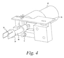
- Figure 4 is a perspective view of a movable portion of the frangible cannula breaking apparatus mounted on the shaft of a rotary drive motor.
- Figure 5 is a perspective view of an alternative drive assembly for rotating the frangible cannula breaking apparatus.
- Figure 6 is a partial front view of the apparatus of Figure 2 , which a fluid bag or pouch mounted in association with the frangible cannula breaking apparatus.
- Figure 7 is an enlarged isolated perspective view of the apparatus of Figure 2 , with a fluid bag or pouch mounted in association with the frangible cannula breaking apparatus.
- Figure 8 is an enlarged isolated perspective view of the apparatus of Figure 1 , with a fluid bag or pouch mounted in association with the frangible cannula breaking apparatus located on the side of the processing apparatus.
- Figure 9 is an enlarged isolated view of the present cannula breaking apparatus showing a container port tube and internal frangible cannula located in an initial loading position in the cannula breaking apparatus.
- Figure 10 is similar to Figure 9 , but illustrates the cannula breaking apparatus in a first position, bending a portion of the frangible cannula through a bending arc X1 relative to the other portion.
- Figure 11 is similar to Figure 10 but illustrates the cannula breaking apparatus in a second position, bending a portion of the frangible cannula in the opposite direction through an opposite bending arc X2 greater than that in Figure 10 .
- Figure 12 is similar to Figure 11 but illustrates the cannula breaking apparatus in a third position, bending a portion of the frangible cannula in the opposite direction of Figure 11 , and through a bending arc X3 approximately the same or greater than in Figure 11 .
- Figure 13 is similar to Figure 12 but illustrates the cannula breaking apparatus in a fourth position, bending a portion of the frangible cannula in the opposite direction of Figure 12 , and through a bending arc X4 approximately the same or greater than in Figure 12 .
- Figure 14 illustrates the frangible cannula in the port tube of Figure 9 after it has been broken and the port tube is open to fluid flow.
- Figure 1 illustrates durable or reusable fluid processing apparatus and more specifically a blood processing device or apparatus 10 for processing a container of blood previously collected from a source such as a human donor or patient, animal (e.g., equine blood), umbilical cord blood, etc.
- a source such as a human donor or patient, animal (e.g., equine blood), umbilical cord blood, etc.
- the illustrated durable processing apparatus 10 is intended to cooperate with a disposable fluid flow or blood processing flow circuit that may include, for example, a primary blood bag or pouch, one or more satellite containers that can be empty or contain a nutritional or other fluid, and associated flow tubing filters and flow control devices, including one or more frangible cannulas.
- the apparatus 10 controls the flow of fluids through the fluid circuit to carry out one or more desired processes such as expression of plasma and/or red cells from a primary container and into a satellite container in combination with, if desired, a preservative.
- the apparatus 10 may include a front loading station 12 where a bag or pouch of blood can be suspended, a user interface 14 for receiving user commands and/or providing information, assorted valves 16, tube sealers/valves 18 and detectors 20, hangers 22 for filters and other hangers for additional bags or pouches, and one or more scales 24 for weighing containers, such as plasma, whole blood and other containers, and such additional features as may be desired.
- a front loading station 12 where a bag or pouch of blood can be suspended
- a user interface 14 for receiving user commands and/or providing information
- assorted valves 16 tube sealers/valves 18 and detectors
- hangers 22 for filters and other hangers for additional bags or pouches
- one or more scales 24 for weighing containers, such as plasma, whole blood and other containers, and such additional features as may be desired.
- the apparatus preferably includes as least one apparatus 26 for breaking and opening a frangible flow control cannula in the fluid flow circuit.
- the processing apparatus 10 includes two frangible cannula breaking devices 26, one on the front panel 28 of the processing apparatus and one on the side panel 30.
- the front panel 28 includes a loading station 12 at which location a bag or pouch of collected blood may be suspended from mounting pins 32 that extend from the front panel.
- the pins may be attached to a scale or weighing apparatus for weighing the suspended bag.
- the pins may be exchangeable to fit bags from different manufacturers and may have tapered or pointed ends for penetration of bags not supplied with pre-arranged eyelets or slits for mounting.
- the frangible cannula breaking apparatus 26 is situated above the bag mounting pins 32.
- the cannula breaking apparatus has two loading or docking areas or stations into which the cannula is to be positioned, a first or lower station has spaced - apart surfaces, preferably spaced pins 34 (e.g., fixation pins) protruding from the front panel, and a second or upper station that has slot or groove between spaced surfaces formed by spaced fingers or wings 36 of a u-shaped channel or saddle 38.
- the pins 34 of the lower station are fixed relative to the front panel and to one another.
- the pins 34 are also preferably interchangeable, such as with the associated bag support pins 32, to accommodate bags of different manufacturers.
- the first or lower station has a fixed position on the processing apparatus.
- the second or upper station is, in contrast to the first station, movable and preferably rotatable relative to the front panel and to the first station pins 34.
- first station rotatable and the second station fixed or both stations could be rotatable relative to one another.
- relative locations may also be reversed (effectively rotated 180 degrees), as may be required or beneficial for different containers/bags.
- the fingers or wings 36 may be of any suitable shape or size and may be configured for the particular frangible cannula to be opened. For example, if a user typically employs the processing apparatus 10 with a fluid circuit or bags from a manufacturer or supplier that uses a frangible cannula of a particular design or material, the fingers or wings may be configured to cooperate most effectively with that particular frangible cannula. Compare, for example, the cross-sectional shapes of the fingers or wings 36 of Figures 3 with those of Figure 7 .
- the fingers or wings may be wider or narrower, have different cross-section shapes, such as round, oval, elliptical or rectangular, straight or curved sides, rounded corners or sharper corners and the like, such as may make the breaker more effective with a particular frangible cannula design or material.
- a selection of saddles could be available to allow the processing apparatus to be customized for use with a particular frangible cannula design or material or, alternatively, the processing apparatus 10 could be provided with a more universally applicable finger/wing shape and size that works with a wide variety of cannula designs or style or materials. This discussion also fully applies the size and shape of stationary pins 34.
- the apparatus 10 also could be programmable to vary the actual cannula breaking action depending on the particular cannula being broken.
- frangible cannula breaking apparatus 26 is situated above the bag mounting pins 32 on the front panel, as can be seen in Figure 1 , the frangible cannula breaker 26, on the side panel 30 is located below bag support or mounting pins 40 and the first and second stations formed by pins 42 and saddle 44 are inverted relative to the respective positions on the front panel 28.
- Additional cannula breaking apparatus can be provided on the apparatus at any suitable location and in any orientation for cooperation with the desired tubing or bag containing the frangible cannula to be broken, such as for use with containers from different manufacturers where a different orientation may be beneficial.
- Additional cannula breaking apparatus in accordance with the subject matter herein could also be provided on ancillary flow control apparatus used with the processing apparatus 10, or could be provided as a freestanding unit for use in a variety of settings not necessarily associated with the processing apparatus 10.
- FIG 4 shows an isolated perspective view of the saddle 38, which defines the spaced apart surfaces of the second cannula docking/loading station on front panel 28.
- saddle 38 is mounted on rotary shaft 46 connected to electrical motor, such as a DC drive motor or stepper motor 48, such as with a position encoder to allow monitoring of the rotational position of the motor.
- Electrical motor such as a DC drive motor or stepper motor 48, such as with a position encoder to allow monitoring of the rotational position of the motor.
- Support frame 50 mounts the motor 48 within the processing apparatus 10 behind front panel 28, and shaft 46 extends through the front panel to position the saddle as shown in Figures 1 - 3 , above an in alignment with first station pins 34.
- the saddle 38 is attached to motor-driven shaft 46.
- Spaced apart fingers or wings 36 extend from diametrically opposed positions on the base, forming u-shaped slot into which part of the frangible cannula is positioned or docked.
- the saddle 38 is mounted in an off-center relation to the shaft, with the center of saddle base being vertically offset from the center (or axis of rotation) of shaft 46. This off-center position has a benefit in breaking the cannula and encouraging separation of the cannula portions after breaking to better assure a fully open fluid flow path. The consequence of this positioning will be more evident from the discussion below.
- FIG. 5 illustrates an alternative drive assembly, generally at 70 for rotating the saddle 38 of the cannula breaking apparatus with increased torque.
- This assembly may be used as needed instead of the direct drive assembly of Figure 4 , for any desired cannula breaker where extra torque is desired.
- This assembly includes a generally L-shaped mounting base 72 for mounting behind the front panel 28 of processing apparatus 10.
- a motor 74 such as an electric, e.g., stepper motor, is mounted to a horizontal leg 76 of the base 72.
- Saddle 38 is mounted on the end of rotary shaft 46, which is rotatably mounted in a vertical leg 78 of base 72 for extension through the front panel 28.
- the assembly includes a power transmission 80.
- the transmission may include gears, belts or pulleys, but is illustrated using a pair of beveled gears 82 and 84 rotationally mounted on the base 72.
- Bevel gear 82 is rotated directly or indirectly by drive motor 74 and bevel gear 84 is attached directly or indirectly to shaft 46.
- the bevel gears are engaged with one another so that rotation of the motor 74 and bevel gear 82 drives bevel gear 84 to rotate shaft 46.
- gear 82 is of smaller diameter that gear 84.
- the rotation speed (RPM) of the larger bevel gear is slower than the rotational speed (RPM) of the smaller bevel gear, and the torque generated by the motor is amplified by the gear train so as to provide increased torque to shaft 46 to better assure sufficient torque for breaking the frangible cannula.
- Figure 6 shows the front panel 28 of processing apparatus 10, with a bag or pouch 52 mounted thereon and with certain portions of the processing apparatus removed for ease of viewing.
- the bag or pouch 52 may contain a quantity of blood previously collected from a donor or patient.
- the blood bag will have previously been subjected to centrifugation to separate the blood cells based on density.
- the bag 52 is suspended on the front panel 28 by inserting mounting pins 32 through matching eyelets 54 in the end perimeter of the bag.
- the particular processing apparatus 10 includes a movable pressure plate P which can be automatically moved by the processing apparatus to contact and compress the bag 52 to express blood or blood components from the bag.
- the plate P and associated apparatus are removed in Figure 5 for ease of viewing.
- the bag includes a port tube 56 that communicates with the interior of the bag for flowing fluid into or from the bag.
- port tube 56 is sealed by an internal frangible cannula 58.
- the port tube 56, internal frangible cannula 58 and breaking apparatus 26 are shown in enlarged isolated detail in Figures 7-14 , and reference should be made to those figures.
- the frangible cannula 58 shown in Figures 9-14 is but one example of frangible cannulas that may be opened using the present apparatus, and the present subject matter is not limited to the particular cannula design details shown.
- the frangible cannula 58 as with most such frangible cannulas in the medical fluid or blood processing fields, has first and second portions 60 and 62, preferably elongated and axially aligned, connected by a breakable junction 64 of relatively thin material.
- the frangible cannula is sealed within the port (or other flow tubing) and initially blocks fluid flow. Flexing of one portion of the cannula relative to the other portion causes the frangible junction to break and opens the lumen of the port tube to flow of fluid therethrough.
- the first portion 60 of cannula 58 is in the form of a hollow tube, sealed at its upper end by the solid second portion 62 which has radially extending ribs or wings 63 to engage the inner surface of the tube when the cannula is broken while allowing fluid to flow past.
- Other manufacturers may use other structures, such as pins or other configurations to frictionally engage the inner surface of the port or other tube, and the present subject matter is not limited to a particular structure.
- the first portion 60 is fixedly attached within the port tube such as by solvent bonding, heat bonding or the like.
- the first and second portions are joined by a relatively thin web of plastic material that breaks reasonably easily when the portions are relatively flexed.
- frangible cannula breaking apparatus when bag 52 is suspended, such as from mounting pins 32, the port tube 56 and frangible cannula 58 within the tube is conveniently mounted proximal to, and preferably in alignment with, the breaking apparatus 26.
- the port tube 56 and frangible cannula 58 are, by reason of the relative location between the bag support (mounting pins 32) and the pins 34 and saddle 38, located so as to be adjacent to and aligned with the breaking apparatus 26 -- with the first portion 60 of the frangible cannula 58 and the portion of the port tube in which it is located being positioned in or proximal to the first docking or loading station between pins 32 and the second portion 62 of the frangible cannula 58 and the portion of the port tube in which it is located being positioned in or proximal to the second docking or loading station between the spaced fingers 36 of saddle 38.
- the operator may then simply confirm proper positioning or, with relative ease, position the port tube and frangible cannula in proper association with the first and second cannula breaker stations.
- the frangible junction 64 of the cannula is located substantially in axial alignment with or in proximity to the axis of the rotary shaft 46, which promotes fracturing when the breaking apparatus is actuated.
- the processing apparatus preferably includes one, two or more sensors, such as an optical sensor "S" in the front panel, to detect the presence of the port tube in the proper position and enable further functioning of the breaker apparatus. Other types of sensors or detectors could also be used.
- Resilient rings 65 on pins 34 assist in holding the port tube 56 between the pins 34 during the cannula breaking, and the port tube can be positioned between the rings 65 and the face of the processing apparatus 10 or the rings can be located between the port tube and the face of the apparatus if desired.
- rings 65 a cylindrical shaft or block with an annular flange at one end could be used. This may find application more particularly with certain containers such as, for example, a whole blood pouch suspend on the side of the process apparatus.
- the actual breaking and opening of the frangible cannula preferably occurs automatically in response to a command from the operator or from the processing control system for the processing apparatus, and preferably only after the sensor S and control system determine that the frangible cannula port tube is properly located with the breaker apparatus.
- the motor 48 rotates or pivots the saddle 38 (and the second part of the frangible cannula) in one direction, such as clockwise about center of rotation C, through a selected angle X1 from a loading position ( Fig 9 ) to a first bent position ( Fig. 10 ).
- Angle X1 may be any suitable amount of angle, and may extend either clockwise or counterclockwise, to fracture or begin to fracture the breakable junction 64 of cannula 58, and the amount and direction of rotation may be different for other cannula configurations or materials or suppliers. Angle X1 will typically be between 0 and 90 degrees and may be less than 60 degrees, such as 45 degrees or less, for example between about 15 and 40 degrees. While the second portion of the cannula is bent to angle X1 relative to the vertical axis, the first portion 60 of the frangible cannula 58 is held sufficiently vertical and stationary by fixed pins 34 to promote fracture of the breakable junction 64.
- the motor 48 reverses direction and pivots the saddle 44 and cannula portion 62 in the reverse direction, e.g. counterclockwise, preferably to a second position at an angle X2 about center C, as shown in Figure 11 , to further induce or cause fracture of the cannula 58.
- This angle X2 may be, for the particular cannula shown herein, preferably greater than the angle X1 in the first position and may be as much as 70-80 degrees.
- the motor then reverses again to rotate the cannula portion 62 to a third position with an angle X3 as shown in Figure 12 , which may be about equal to or greater than angle X2.
- a further rotation counterclockwise to angle X4 is shown in Figure 13 and angle X4 may be about the same as or greater or lesser than X3.
- the motor may repeat this bending back and forth in opposite directions a fixed number of times, as is needed for the particular cannula being broken, returning the cannula eventually to the loading position, but in a fully open condition as shown in Figure 14 .
- one cycle back and forth may be enough to fully open the cannula.
- repeated cycles back and forth may be required. This may be predetermined and the processing apparatus configured for a particular cannula, as described below.
- the cannula may be flexed back and forth until an open flow path is detected by the processing apparatus, such as be detecting fluid flow through the port tube or a change in pressure in the bag 52, or by detecting a change in weight in one of the weight scales which is indicative that the cannula is open and fluid is flowing.
- Figure 14 illustrates how the frangible cannula 58 may appear after repeated flexing of the cannula by the apparatus of the present disclosure, with the frangible or breakable junction 64 broken and portions 60 and 62 separated, thus opening the port tube for flow of blood or other liquid from or into the bag 52 without required manual manipulation by the operator or user.
- Figures 9-14 illustrate the cannula breaker action diagrammatically for purposes of illustration and simplicity.
- the fingers or wings 36 rotate, of course, they actually engage and press against the side of the port tube, and bend the cannula within the port tube. More specifically, with the fingers or wings 36 of the shape shown herein, which are preferably but not exclusively elongated in a vertical direction, opposite corners of the fingers will tend to engage the port tube when rotated.
- upper inside corner C1 of trailing finger 36 and lower inside corner C2 of the lead finger 36 will tend to engage most directly against and depress the wall of the port tube ("trailing" and "leading" are with reference to the direction of rotation).
- the fingers or wings 36 may be pivoted back and forth several cycles, with increasing degrees of rotation up to about 70-80 degrees from vertical in both clockwise and counterclockwise directions.
- Other styles of frangible cannulas or cannulas made of more rigid materials may require only one or two cycles of the fingers to break and separate the cannula to allow flow through the port tube.
- control system of the processing apparatus 10 may be programmable to vary the number of cycles and degree of rotation, depending on the frangible cannula to be broken.
- the control system may include a user selection feature, where the user selects from one or more frangible breaking protocols depending on the type or source of cannula to be broken, or the system may be configured to set the appropriate protocol upon reading a barcode or RFID tag associated with the particular bag or pouch.
- frangible breaking protocols depending on the type or source of cannula to be broken
- the cannula breaking protocol may set at the factory or by service personnel and not routinely changed by the processing center.
- the illustrated apparatus also include one or more frangible cannula breakers on side panel 30 or elsewhere on the processing apparatus 10 or on ancillary equipment used in conjunction with the apparatus that functions substantially as described herein.
- the breaker On the side panel, the breaker is located to be employed with bags or pouches that are suspended in an inverted position relative to the bag 52.
- the cannula breaker functions essentially as described above, but with the relative parts inverted as compared to the front panel. Also, it is similarly positioned to be in proximity to the port tube and frangible cannula of the pouch or bag suspended on the side panel from the respective container mount.
- frangible cannula breaking apparatus although shown in combination with a blood processing apparatus 10, may be freestanding and independent of any other associated processing device or apparatus.
Landscapes
- Health & Medical Sciences (AREA)
- Life Sciences & Earth Sciences (AREA)
- Engineering & Computer Science (AREA)
- Heart & Thoracic Surgery (AREA)
- Mechanical Engineering (AREA)
- Forests & Forestry (AREA)
- Anesthesiology (AREA)
- Hematology (AREA)
- Animal Behavior & Ethology (AREA)
- General Health & Medical Sciences (AREA)
- Public Health (AREA)
- Veterinary Medicine (AREA)
- Biomedical Technology (AREA)
- Pulmonology (AREA)
- Medical Preparation Storing Or Oral Administration Devices (AREA)
- External Artificial Organs (AREA)
Abstract
Description
- The subject matter of this application relates to devices and methods for opening frangible closures or valves within fluid passageways, such as within fluid flow paths associated with blood collection or processing flow circuits or systems.
- It is well known in the medical field and particularly in the blood banking field to employ frangible internal flow control valves in pre-assembled and pre-sterilized fluid flow circuits that are used in the collection and/or processing of human or animal blood or blood components, including without limitation umbilical cord blood (hereinafter "blood"). Such valves are commonly referred to as frangible or breakable valves, closures or cannulas and will referred to as cannulas herein. Numerous patents disclose various configurations of such frangible cannulas. See, for example,
U.S. Patents Nos. 4,181,140 ;4,294,247 ;4,340,049 ;4,386,622 and6,132,413 , all of which are hereby incorporated by reference. - Such frangible cannulas may be located at any suitable location in a fluid flow system, such as within flexible fluid flow tubing for controlling flow through the tubing or within flexible port tubes associated with liquid filled or liquid-receiving containers to control flow into or from the container. Although the particular design can vary, typically such cannulas have two portions separated by a breakable zone or junction formed by an area of reduced or limited thickness. The user can open the cannulas by external manipulation without disturbing the internal sterility of the fluid flow path. For example, by gripping the flexible tubing or port tube and bending or flexing the cannula portions about the breakable junction, the junction can be broken and the portions separated to open the flow path. Although such is routinely done manually, it has been proposed to provide automated frangible cannula breakers, which breakers may be embodied in devices for processing pharmaceutical or biological fluids such as blood.
- The present subject matter is directed to apparatus and method for opening such frangible cannulas.
- In one aspect or implementation of the present subject matter, apparatus is provided for breaking a frangible cannula located inside a flexible flow path. The frangible cannula is of the type including first and second portions with a breakable junction therebetween, which junction may be broken by relative bending of the portions. The breaking apparatus includes a first station in which the portion of the flow path containing the first portion of the frangible cannula is positionable and a second station in which the portion of the flow path containing the second portion of the cannula is positionable. The first and/or second station is movable relative to the other station to bend the flow path and the portion of the cannula therein relative to the other portion of the cannula to break the breakable junction and preferably further separate the portions to open the flow path to flow therethrough.
- In another aspect or implementation of the present subject matter, which may be used with the above aspect or implementation, the first and/or second station is movable to bend the portion of the cannula therein in one direction relative to the other portion and in a direction opposite to the one direction.
- In another aspect or implementation of the present subject matter, which may be used with any one of the above aspects or implementations, the first and/or second station is configured to repeatedly bend the portion therein in opposite directions.
- In another aspect or implementation of the present subject matter, which may be used with any one of the above aspects or implementations, the first and/or second station comprises first spaced apart surfaces for receiving the flow path and a portion of the frangible cannula therebetween.
- In another aspect or implementation of the present subject matter, which may be used with the above aspect or implementation, the spaced apart surfaces of one of the stations comprise fixed projecting members for receiving the flow path and a portion of the frangible cannula between the members.
- In another aspect or implementation of the present subject matter, which may be used with any one of the above aspects or implementations, the first and/or second station is configured for movement through an arc relative to a center of rotation.
- In another aspect or implementation of the present subject matter, which may be used with any one of the above aspects or implementations, the each station includes spaced apart surfaces for receiving the flow path and a portion of the cannula therebetween.
- In another aspect or implementation of the present subject matter, which may be used with any one of the above aspects or implementations, the spaced apart surfaces of the first and/or second stations are off-set relative to a center of the arc of movement of one or both of the stations.
- In another aspect or implementation of the present subject matter, which may be used with any one of the above aspects or implementations, the first and/or second stations are located so that when the frangible cannula is received therein, the breakable portion of the frangible cannula is generally axially aligned with or in proximity to the center of an arc of movement of such station or stations.
- In another aspect or implementation of the present subject matter, which may be used with the apparatus employed for breaking a frangible cannula controlling flow through a port of fluid-containing bag, the apparatus includes a bag support for suspending the bag therefrom. The bag support is located relative to the first and second stations such that when a bag is suspended on the support, the first and second portions of the frangible cannula are located in proximity with the first and second stations for ease of insertion or positioning therein.
- In another aspect or implementation of the present subject matter, which may be used with any one of the above aspects or implementations, the first and/or second station may be mounted on a rotary actuator.
- In another aspect or implementation of the present subject matter, which may be used with any one of the above aspects or implementations, the first and/or second station is operable to bend the second portion through a bending arc in opposite directions relative to an initial loading position to break the cannula and move the portions further apart to open the flow path to fluid flow.
- In another aspect or implementation of the present subject matter, which may be used with any one of the above aspects or implementations, a detector is provided for detecting when the frangible cannula is broken.
- In another aspect or implementation of the present subject matter, which may be used with any one of the above aspects or implementations, the first and/or second station comprises a generally U-shaped recess or saddle for receiving the flow path and a portion of the frangible cannula.
- In accordance with another aspect or implementation of the present subject matter, a method for breaking a frangible cannula located within a flexible flow path comprises mounting the flow path in a cannula breaker device having a first station for receiving a first portion of the cannula and a movable second station for receiving a second portion of the cannula, the frangible cannula having a breakable junction between the first and second portions, and actuating the first and/or second station to cause movement of the one station relative to the other station to break the breakable junction.
- In accordance with another aspect, which may be used with the above aspect, the breaker device includes a detector for detecting whether the frangible cannula is broken, and the method includes detecting whether the cannula is broken.
- In accordance with another aspect which may be used with any one of the above aspects, the first or second station may be in a fixed or stationary position.
- These and other aspects of the present subject matter are shown for purposes of illustration and not limitation in the attached drawings, of which:
-
Figure 1 is a perspective view of blood processing device or apparatus embodying a frangible cannula breaking device and method in accordance with the present subject matter. -
Figure 2 is an elevation view of the front panel of the apparatus ofFigure 1 , with portions removed for ease of viewing. -
Figure 3 is an isolated elevation view enlarged view illustrating the frangible cannula breaking apparatus ofFigure 1 . -
Figure 4 is a perspective view of a movable portion of the frangible cannula breaking apparatus mounted on the shaft of a rotary drive motor. -
Figure 5 is a perspective view of an alternative drive assembly for rotating the frangible cannula breaking apparatus. -
Figure 6 is a partial front view of the apparatus ofFigure 2 , which a fluid bag or pouch mounted in association with the frangible cannula breaking apparatus. -
Figure 7 is an enlarged isolated perspective view of the apparatus ofFigure 2 , with a fluid bag or pouch mounted in association with the frangible cannula breaking apparatus. -
Figure 8 is an enlarged isolated perspective view of the apparatus ofFigure 1 , with a fluid bag or pouch mounted in association with the frangible cannula breaking apparatus located on the side of the processing apparatus. -
Figure 9 is an enlarged isolated view of the present cannula breaking apparatus showing a container port tube and internal frangible cannula located in an initial loading position in the cannula breaking apparatus. -
Figure 10 is similar toFigure 9 , but illustrates the cannula breaking apparatus in a first position, bending a portion of the frangible cannula through a bending arc X1 relative to the other portion. -
Figure 11 is similar toFigure 10 but illustrates the cannula breaking apparatus in a second position, bending a portion of the frangible cannula in the opposite direction through an opposite bending arc X2 greater than that inFigure 10 . -
Figure 12 is similar toFigure 11 but illustrates the cannula breaking apparatus in a third position, bending a portion of the frangible cannula in the opposite direction ofFigure 11 , and through a bending arc X3 approximately the same or greater than inFigure 11 . -
Figure 13 is similar toFigure 12 but illustrates the cannula breaking apparatus in a fourth position, bending a portion of the frangible cannula in the opposite direction ofFigure 12 , and through a bending arc X4 approximately the same or greater than inFigure 12 . -
Figure 14 illustrates the frangible cannula in the port tube ofFigure 9 after it has been broken and the port tube is open to fluid flow. - Turning now to a more detail description,
Figure 1 illustrates durable or reusable fluid processing apparatus and more specifically a blood processing device orapparatus 10 for processing a container of blood previously collected from a source such as a human donor or patient, animal (e.g., equine blood), umbilical cord blood, etc. - In the present embodiment, the illustrated
durable processing apparatus 10 is intended to cooperate with a disposable fluid flow or blood processing flow circuit that may include, for example, a primary blood bag or pouch, one or more satellite containers that can be empty or contain a nutritional or other fluid, and associated flow tubing filters and flow control devices, including one or more frangible cannulas. Theapparatus 10 controls the flow of fluids through the fluid circuit to carry out one or more desired processes such as expression of plasma and/or red cells from a primary container and into a satellite container in combination with, if desired, a preservative. To that end, theapparatus 10 may include afront loading station 12 where a bag or pouch of blood can be suspended, auser interface 14 for receiving user commands and/or providing information, assortedvalves 16, tube sealers/valves 18 anddetectors 20,hangers 22 for filters and other hangers for additional bags or pouches, and one ormore scales 24 for weighing containers, such as plasma, whole blood and other containers, and such additional features as may be desired. - In accordance with the present subject matter the apparatus preferably includes as least one
apparatus 26 for breaking and opening a frangible flow control cannula in the fluid flow circuit. As illustrated, theprocessing apparatus 10 includes two frangible cannulabreaking devices 26, one on thefront panel 28 of the processing apparatus and one on theside panel 30. - As seen in
Figures 1 - 3 , thefront panel 28 includes aloading station 12 at which location a bag or pouch of collected blood may be suspended from mountingpins 32 that extend from the front panel. The pins may be attached to a scale or weighing apparatus for weighing the suspended bag. The pins may be exchangeable to fit bags from different manufacturers and may have tapered or pointed ends for penetration of bags not supplied with pre-arranged eyelets or slits for mounting. - The frangible
cannula breaking apparatus 26 is situated above thebag mounting pins 32. As shown, on the front panel the cannula breaking apparatus has two loading or docking areas or stations into which the cannula is to be positioned, a first or lower station has spaced - apart surfaces, preferably spaced pins 34 (e.g., fixation pins) protruding from the front panel, and a second or upper station that has slot or groove between spaced surfaces formed by spaced fingers orwings 36 of a u-shaped channel orsaddle 38. As illustrated, thepins 34 of the lower station are fixed relative to the front panel and to one another. Thepins 34 are also preferably interchangeable, such as with the associatedbag support pins 32, to accommodate bags of different manufacturers. Thus the first or lower station has a fixed position on the processing apparatus. The second or upper station is, in contrast to the first station, movable and preferably rotatable relative to the front panel and to thefirst station pins 34. Although described herein with reference to the relative positioning and movement shown, it should be understood that the relative position and movement may be reversed, with the first station rotatable and the second station fixed or both stations could be rotatable relative to one another. And the relative locations may also be reversed (effectively rotated 180 degrees), as may be required or beneficial for different containers/bags. - The fingers or
wings 36 may be of any suitable shape or size and may be configured for the particular frangible cannula to be opened. For example, if a user typically employs theprocessing apparatus 10 with a fluid circuit or bags from a manufacturer or supplier that uses a frangible cannula of a particular design or material, the fingers or wings may be configured to cooperate most effectively with that particular frangible cannula. Compare, for example, the cross-sectional shapes of the fingers orwings 36 ofFigures 3 with those ofFigure 7 . Specifically, the fingers or wings may be wider or narrower, have different cross-section shapes, such as round, oval, elliptical or rectangular, straight or curved sides, rounded corners or sharper corners and the like, such as may make the breaker more effective with a particular frangible cannula design or material. A selection of saddles could be available to allow the processing apparatus to be customized for use with a particular frangible cannula design or material or, alternatively, theprocessing apparatus 10 could be provided with a more universally applicable finger/wing shape and size that works with a wide variety of cannula designs or style or materials. This discussion also fully applies the size and shape of stationary pins 34. As discussed in more detail below, theapparatus 10 also could be programmable to vary the actual cannula breaking action depending on the particular cannula being broken. - Although the frangible
cannula breaking apparatus 26 is situated above the bag mounting pins 32 on the front panel, as can be seen inFigure 1 , thefrangible cannula breaker 26, on theside panel 30 is located below bag support or mounting pins 40 and the first and second stations formed by pins 42 andsaddle 44 are inverted relative to the respective positions on thefront panel 28. Additional cannula breaking apparatus can be provided on the apparatus at any suitable location and in any orientation for cooperation with the desired tubing or bag containing the frangible cannula to be broken, such as for use with containers from different manufacturers where a different orientation may be beneficial. Additional cannula breaking apparatus in accordance with the subject matter herein could also be provided on ancillary flow control apparatus used with theprocessing apparatus 10, or could be provided as a freestanding unit for use in a variety of settings not necessarily associated with theprocessing apparatus 10. -
Figure 4 shows an isolated perspective view of thesaddle 38, which defines the spaced apart surfaces of the second cannula docking/loading station onfront panel 28. As shown there,saddle 38 is mounted onrotary shaft 46 connected to electrical motor, such as a DC drive motor orstepper motor 48, such as with a position encoder to allow monitoring of the rotational position of the motor.Support frame 50 mounts themotor 48 within theprocessing apparatus 10 behindfront panel 28, andshaft 46 extends through the front panel to position the saddle as shown inFigures 1 - 3 , above an in alignment with first station pins 34. - As best seen in
Figure 4 , thesaddle 38 is attached to motor-drivenshaft 46. Spaced apart fingers orwings 36 extend from diametrically opposed positions on the base, forming u-shaped slot into which part of the frangible cannula is positioned or docked. Thesaddle 38 is mounted in an off-center relation to the shaft, with the center of saddle base being vertically offset from the center (or axis of rotation) ofshaft 46. This off-center position has a benefit in breaking the cannula and encouraging separation of the cannula portions after breaking to better assure a fully open fluid flow path. The consequence of this positioning will be more evident from the discussion below. -
Figure 5 illustrates an alternative drive assembly, generally at 70 for rotating thesaddle 38 of the cannula breaking apparatus with increased torque. This assembly may be used as needed instead of the direct drive assembly ofFigure 4 , for any desired cannula breaker where extra torque is desired. This assembly includes a generally L-shapedmounting base 72 for mounting behind thefront panel 28 ofprocessing apparatus 10. Amotor 74, such as an electric, e.g., stepper motor, is mounted to ahorizontal leg 76 of thebase 72.Saddle 38 is mounted on the end ofrotary shaft 46, which is rotatably mounted in avertical leg 78 ofbase 72 for extension through thefront panel 28. For connecting thedrive motor 74 to theshaft 46, the assembly includes apower transmission 80. The transmission may include gears, belts or pulleys, but is illustrated using a pair of beveled gears 82 and 84 rotationally mounted on thebase 72.Bevel gear 82 is rotated directly or indirectly bydrive motor 74 andbevel gear 84 is attached directly or indirectly toshaft 46. The bevel gears are engaged with one another so that rotation of themotor 74 andbevel gear 82drives bevel gear 84 to rotateshaft 46. As seen inFigure 5 ,gear 82 is of smaller diameter that gear 84. As a result, the rotation speed (RPM) of the larger bevel gear is slower than the rotational speed (RPM) of the smaller bevel gear, and the torque generated by the motor is amplified by the gear train so as to provide increased torque toshaft 46 to better assure sufficient torque for breaking the frangible cannula. -
Figure 6 shows thefront panel 28 ofprocessing apparatus 10, with a bag orpouch 52 mounted thereon and with certain portions of the processing apparatus removed for ease of viewing. More specifically, the bag orpouch 52 may contain a quantity of blood previously collected from a donor or patient. Typically, the blood bag will have previously been subjected to centrifugation to separate the blood cells based on density. - The
bag 52 is suspended on thefront panel 28 by inserting mountingpins 32 through matchingeyelets 54 in the end perimeter of the bag. Theparticular processing apparatus 10, as seen inFigure 1 , includes a movable pressure plate P which can be automatically moved by the processing apparatus to contact and compress thebag 52 to express blood or blood components from the bag. The plate P and associated apparatus are removed inFigure 5 for ease of viewing. As is common in blood bags, the bag includes aport tube 56 that communicates with the interior of the bag for flowing fluid into or from the bag. As illustrated,port tube 56 is sealed by an internalfrangible cannula 58. Theport tube 56, internalfrangible cannula 58 and breakingapparatus 26 are shown in enlarged isolated detail inFigures 7-14 , and reference should be made to those figures. Thefrangible cannula 58 shown inFigures 9-14 is but one example of frangible cannulas that may be opened using the present apparatus, and the present subject matter is not limited to the particular cannula design details shown. Thefrangible cannula 58, as with most such frangible cannulas in the medical fluid or blood processing fields, has first andsecond portions breakable junction 64 of relatively thin material. Typically made of rigid plastic, the frangible cannula is sealed within the port (or other flow tubing) and initially blocks fluid flow. Flexing of one portion of the cannula relative to the other portion causes the frangible junction to break and opens the lumen of the port tube to flow of fluid therethrough. - As best seen in
Figure 9 , thefirst portion 60 ofcannula 58 is in the form of a hollow tube, sealed at its upper end by the solidsecond portion 62 which has radially extending ribs orwings 63 to engage the inner surface of the tube when the cannula is broken while allowing fluid to flow past. Other manufacturers may use other structures, such as pins or other configurations to frictionally engage the inner surface of the port or other tube, and the present subject matter is not limited to a particular structure. Thefirst portion 60 is fixedly attached within the port tube such as by solvent bonding, heat bonding or the like. The first and second portions are joined by a relatively thin web of plastic material that breaks reasonably easily when the portions are relatively flexed. Flexing of the second portion relative to the first and preferably axial separation of the second from the first opens the port tube to fluid flow. This particular frangible cannula is described in greater detail in priorUS patent no. 6,132,413 , incorporated by reference herein, and is shown only for purposes of illustration. The present breaking apparatus is intended to work with frangible cannulas of various and differing specific designs. - Turning now to a more detailed discussion of the frangible cannula breaking apparatus and its method of use, as will be appreciated from
Figures 6-8 , whenbag 52 is suspended, such as from mountingpins 32, theport tube 56 andfrangible cannula 58 within the tube is conveniently mounted proximal to, and preferably in alignment with, the breakingapparatus 26. More specifically, when a bag is suspended on the front ofapparatus 10, theport tube 56 andfrangible cannula 58 are, by reason of the relative location between the bag support (mounting pins 32) and thepins 34 andsaddle 38, located so as to be adjacent to and aligned with the breakingapparatus 26 -- with thefirst portion 60 of thefrangible cannula 58 and the portion of the port tube in which it is located being positioned in or proximal to the first docking or loading station betweenpins 32 and thesecond portion 62 of thefrangible cannula 58 and the portion of the port tube in which it is located being positioned in or proximal to the second docking or loading station between the spacedfingers 36 ofsaddle 38. The operator may then simply confirm proper positioning or, with relative ease, position the port tube and frangible cannula in proper association with the first and second cannula breaker stations. In this position, thefrangible junction 64 of the cannula is located substantially in axial alignment with or in proximity to the axis of therotary shaft 46, which promotes fracturing when the breaking apparatus is actuated. The processing apparatus preferably includes one, two or more sensors, such as an optical sensor "S" in the front panel, to detect the presence of the port tube in the proper position and enable further functioning of the breaker apparatus. Other types of sensors or detectors could also be used. Resilient rings 65 on pins 34 (seeFigure 8 ) assist in holding theport tube 56 between thepins 34 during the cannula breaking, and the port tube can be positioned between the rings 65 and the face of theprocessing apparatus 10 or the rings can be located between the port tube and the face of the apparatus if desired. Alternatively, in place of rings 65, a cylindrical shaft or block with an annular flange at one end could be used. This may find application more particularly with certain containers such as, for example, a whole blood pouch suspend on the side of the process apparatus. - The actual breaking and opening of the frangible cannula preferably occurs automatically in response to a command from the operator or from the processing control system for the processing apparatus, and preferably only after the sensor S and control system determine that the frangible cannula port tube is properly located with the breaker apparatus. Referring to
Figures 9 and 10 , upon command, themotor 48 rotates or pivots the saddle 38 (and the second part of the frangible cannula) in one direction, such as clockwise about center of rotation C, through a selected angle X1 from a loading position (Fig 9 ) to a first bent position (Fig. 10 ). In this embodiment, as noted earlier, thesaddle 38 andfingers 36 are off-center relative to the axis ofrotary shaft 46, and thefrangible junction 64 is approximately in alignment with or in proximity to the axis ofrotary shaft 46 and center of rotation C. Although such positioning may be beneficial, it is not required for all embodiments. Angle X1 may be any suitable amount of angle, and may extend either clockwise or counterclockwise, to fracture or begin to fracture thebreakable junction 64 ofcannula 58, and the amount and direction of rotation may be different for other cannula configurations or materials or suppliers. Angle X1 will typically be between 0 and 90 degrees and may be less than 60 degrees, such as 45 degrees or less, for example between about 15 and 40 degrees. While the second portion of the cannula is bent to angle X1 relative to the vertical axis, thefirst portion 60 of thefrangible cannula 58 is held sufficiently vertical and stationary byfixed pins 34 to promote fracture of thebreakable junction 64. - After pivoting the
saddle 38 andsecond cannula portion 62 in the first direction as seen inFigure 10 , themotor 48 reverses direction and pivots thesaddle 44 andcannula portion 62 in the reverse direction, e.g. counterclockwise, preferably to a second position at an angle X2 about center C, as shown inFigure 11 , to further induce or cause fracture of thecannula 58. This angle X2 may be, for the particular cannula shown herein, preferably greater than the angle X1 in the first position and may be as much as 70-80 degrees. The motor then reverses again to rotate thecannula portion 62 to a third position with an angle X3 as shown inFigure 12 , which may be about equal to or greater than angle X2. A further rotation counterclockwise to angle X4 is shown inFigure 13 and angle X4 may be about the same as or greater or lesser than X3. - The motor may repeat this bending back and forth in opposite directions a fixed number of times, as is needed for the particular cannula being broken, returning the cannula eventually to the loading position, but in a fully open condition as shown in
Figure 14 . For some cannula of highly rigid materials, one cycle back and forth may be enough to fully open the cannula. For cannulas of somewhat softer material, repeated cycles back and forth may be required. This may be predetermined and the processing apparatus configured for a particular cannula, as described below. Alternatively, the cannula may be flexed back and forth until an open flow path is detected by the processing apparatus, such as be detecting fluid flow through the port tube or a change in pressure in thebag 52, or by detecting a change in weight in one of the weight scales which is indicative that the cannula is open and fluid is flowing.Figure 14 illustrates how thefrangible cannula 58 may appear after repeated flexing of the cannula by the apparatus of the present disclosure, with the frangible orbreakable junction 64 broken andportions bag 52 without required manual manipulation by the operator or user. - It should be noted that
Figures 9-14 illustrate the cannula breaker action diagrammatically for purposes of illustration and simplicity. When the fingers orwings 36 rotate, of course, they actually engage and press against the side of the port tube, and bend the cannula within the port tube. More specifically, with the fingers orwings 36 of the shape shown herein, which are preferably but not exclusively elongated in a vertical direction, opposite corners of the fingers will tend to engage the port tube when rotated. For example, referring tofigure 11 of the panel of the processing apparatus, upper inside corner C1 of trailingfinger 36 and lower inside corner C2 of thelead finger 36 will tend to engage most directly against and depress the wall of the port tube ("trailing" and "leading" are with reference to the direction of rotation). This action, when repeated, assists in breaking the cannula, particularly with the cannula is made of a somewhat softer or more pliable material, and also tends to push or "walk" thesecond cannula portion 62 axially along the inside of the port tube causing it to further separate from the first cannula portion after frangible portion orzone 64 is broken. For the particular cannula shown in the figures, the fingers orwings 36 may be pivoted back and forth several cycles, with increasing degrees of rotation up to about 70-80 degrees from vertical in both clockwise and counterclockwise directions. Other styles of frangible cannulas or cannulas made of more rigid materials may require only one or two cycles of the fingers to break and separate the cannula to allow flow through the port tube. - In this regard, the control system of the
processing apparatus 10 may be programmable to vary the number of cycles and degree of rotation, depending on the frangible cannula to be broken. The control system may include a user selection feature, where the user selects from one or more frangible breaking protocols depending on the type or source of cannula to be broken, or the system may be configured to set the appropriate protocol upon reading a barcode or RFID tag associated with the particular bag or pouch. For those blood processing centers that tend to use disposable bags and blood collection and processing systems from a single source, with a single cannula configuration, the cannula breaking protocol may set at the factory or by service personnel and not routinely changed by the processing center. - As noted earlier, the illustrated apparatus also include one or more frangible cannula breakers on
side panel 30 or elsewhere on theprocessing apparatus 10 or on ancillary equipment used in conjunction with the apparatus that functions substantially as described herein. On the side panel, the breaker is located to be employed with bags or pouches that are suspended in an inverted position relative to thebag 52. The cannula breaker functions essentially as described above, but with the relative parts inverted as compared to the front panel. Also, it is similarly positioned to be in proximity to the port tube and frangible cannula of the pouch or bag suspended on the side panel from the respective container mount. - Although the breaking
apparatus 26 is described as used with a frangible cannula on the port tube of a container, it also has utility for opening frangible cannulas that are in fluid flow tubing not directly associated with a bag or container port. Also, the frangible cannula breaking apparatus, although shown in combination with ablood processing apparatus 10, may be freestanding and independent of any other associated processing device or apparatus. - While described in terms of the illustrated embodiments, it is understand that the features and implementations of the illustrated design may be varied in a manner apparent to those skilled in the field.
Claims (15)
- Apparatus (10) for breaking a frangible cannula (58) located inside a flexible flow path (56), the frangible cannula (58) including first and second portions (60, 62) with a breakable junction (64) therebetween that may be broken by relative bending of the portions, the apparatus (10) comprising: a first station in which the portion of the flow path (56) containing the first portion (60) of the cannula (58) is positionable and a second movable station in which the portion of the flow path (56) containing the second portion (62) of the cannula (58) is positionable; the first and/or second station being movable relative to the other station through an angle (X) relative to a center of bending (C) and being offset from the center of bending (C) as to bend the flow path (56) and one portion (60,62) of the cannula (58) therein relative to the other portion (62, 60) of the flowpath (56) and the other portion of the cannula therein, such as to break the breakable junction (64).
- The apparatus (10) of claim 1 in which the first and/or second station is movable to bend a portion (60, 62) of the cannula (58) in one direction relative to the other portion (62,60) and in a direction opposite to the one direction.
- The apparatus (10) of claim 2 in which the first and/or second station is movable to bend the portion (62) of the cannula (58) through one angle (X1) in the one direction and through a greater angle (X2) in the opposite direction.
- The apparatus (10) of any of the claims 1-4 in which the first and/or second station comprises spaced apart surfaces for receiving the flow path (56) and a portion (60, 62) of the cannula (58) therebetween, and preferably
the spaced apart surfaces comprise projecting members (32, 36) for receiving the flow path (56) and a portion of the cannula (58) between the members (32, 36). - The apparatus (10) of claim 4 in which the spaced apart surfaces engage the flow path (56) during bending to push or walk a portion (62) of the cannula (58) along the flow path (56) to further separate it from the other cannula portion (60).
- The apparatus (10) of any of the claims 1-5 in which the first and/or second stations are located so that when the frangible cannula (58) is received therein, the breakable portion (64) of the frangible cannula (58) is generally axially aligned or in proximity to the center of bending (C).
- The apparatus (10) of any of the claims 1-6 wherein the the first and/or second station being rotatable relative to the other station through an angle (X) relative to a center of rotation (C) and being offset from the center of rotation (C) as to bend the flow path (56) and one portion (60,62) of the cannula (58) therein relative to the other portion (62, 60) of the flowpath (56) and the other portion of the cannula therein, such as to break the breakable junction (64).
- The apparatus (10) of claim 7 wherein the first and/or second station is mounted on a rotary shaft (42) and the apparatus includes an electrical drive motor (74), such as a DC drive or stepper motor, and a power transmission (80) connecting the motor (74) to the shaft (42) for increasing the motor torque applied to the shaft.
- The apparatus (10) of any of the claims 1-8 including a detector for detecting when the frangible cannula (58) is broken.
- The apparatus (10) of any of the claims 1-9 configured to flow blood through the flow path (56) containing the frangible cannula (58).
- A method of breaking a frangible cannula (58) located within a flexible flow path (56) comprising mounting the flow path (56) in a cannula breaker device (26) having a first station for receiving a first portion (60) of the cannula (58) and a second station for receiving a second portion of the cannula, the frangible cannula (58) having a breakable junction (64) between the first and second portions, and actuating the first and/or second stations to cause movement of the second station relative to the first station through an angle (X) relative to a center of bending (C) to break the breakable junction, the first and/or second stations being offset from the center of bending (C).
- The method of claim 11 wherever the breaker device includes a detector for detecting whether the frangible cannula (58) is broken, and the method includes detecting whether the frangible cannula (58) is broken.
- The method of claim 11 or 12 including pushing or walking the portion (62) of the frangible cannula (58) along the flow path (56_ to further separate if from the other cannula portion (60).
- The method of any of the claims 11-13 in which the first and second stations bend the second portion of the cannula in one direction, preferably through a first angle (X1), and in an opposite direction preferably through a second angle (X2) greater than the first angle.
- The method of any of the claims 11-14 actuating the first and/or second stations to cause rotation of the second station relative to the first station through an angle (X) relative to a center of rotation (C) to break the breakable junction, the first and/or second stations being offset from the center of rotation (C).
Priority Applications (1)
| Application Number | Priority Date | Filing Date | Title |
|---|---|---|---|
| EP19165604.0A EP3527253B1 (en) | 2013-03-15 | 2013-11-08 | Automated frangible cannula breaker |
Applications Claiming Priority (1)
| Application Number | Priority Date | Filing Date | Title |
|---|---|---|---|
| US13/833,990 US9895822B2 (en) | 2013-03-15 | 2013-03-15 | Automated frangible cannula breaker |
Related Child Applications (2)
| Application Number | Title | Priority Date | Filing Date |
|---|---|---|---|
| EP19165604.0A Division-Into EP3527253B1 (en) | 2013-03-15 | 2013-11-08 | Automated frangible cannula breaker |
| EP19165604.0A Division EP3527253B1 (en) | 2013-03-15 | 2013-11-08 | Automated frangible cannula breaker |
Publications (2)
| Publication Number | Publication Date |
|---|---|
| EP2777754A1 true EP2777754A1 (en) | 2014-09-17 |
| EP2777754B1 EP2777754B1 (en) | 2019-05-15 |
Family
ID=49584597
Family Applications (2)
| Application Number | Title | Priority Date | Filing Date |
|---|---|---|---|
| EP13192157.9A Active EP2777754B1 (en) | 2013-03-15 | 2013-11-08 | Automated frangible cannula breaker |
| EP19165604.0A Active EP3527253B1 (en) | 2013-03-15 | 2013-11-08 | Automated frangible cannula breaker |
Family Applications After (1)
| Application Number | Title | Priority Date | Filing Date |
|---|---|---|---|
| EP19165604.0A Active EP3527253B1 (en) | 2013-03-15 | 2013-11-08 | Automated frangible cannula breaker |
Country Status (2)
| Country | Link |
|---|---|
| US (1) | US9895822B2 (en) |
| EP (2) | EP2777754B1 (en) |
Cited By (4)
| Publication number | Priority date | Publication date | Assignee | Title |
|---|---|---|---|---|
| EP3002016A1 (en) * | 2014-10-03 | 2016-04-06 | Fenwal, Inc. | Automated system for processing a biological fluid |
| US20180078694A1 (en) * | 2016-09-21 | 2018-03-22 | Fenwal, Inc. | Disposable Fluid Circuits for Extracorporeal Photopheresis with Integrated Source of Photoactive Agent |
| CN108348742A (en) * | 2015-09-14 | 2018-07-31 | 德国费森尤斯卡比有限公司 | Decoupler equipment for being applied on the closure elements of medical catheter |
| BE1029476A1 (en) | 2021-06-09 | 2023-01-10 | Ignore The Box | Sterilizable tubing for a blood bag set or the like and a closing mechanism therefor, as well as a blood bag set equipped therewith |
Families Citing this family (6)
| Publication number | Priority date | Publication date | Assignee | Title |
|---|---|---|---|---|
| FR2968568B1 (en) * | 2010-12-14 | 2013-01-18 | Maco Pharma Sa | DEVICE FOR BREAKING AT LEAST ONE CLOSURE MEMBER WITH A FLEXIBLE TUBE |
| EP3349842B1 (en) | 2015-09-14 | 2019-07-24 | Fresenius Kabi Deutschland GmbH | Breaker device for acting onto a closure element of a medical tubing |
| PL3260162T3 (en) * | 2016-06-23 | 2020-04-30 | Lmb Technologie Gmbh | Automatic valve breaking device with documentation and control of the breaking process |
| EP3856317B1 (en) * | 2018-09-26 | 2025-03-05 | NxStage Medical, Inc. | Configurable fluid channel sealing devices and methods |
| EP3632484A1 (en) | 2018-10-04 | 2020-04-08 | Fenwal, Inc. | Methods and systems for collecting samples in a photopheresis procedure |
| CN115557042B (en) * | 2022-11-24 | 2023-03-07 | 河北大安制药有限公司 | Plasma bag breaking machine |
Citations (2)
| Publication number | Priority date | Publication date | Assignee | Title |
|---|---|---|---|---|
| US20100132512A1 (en) * | 2008-12-03 | 2010-06-03 | Caridianbct, Inc. | Frangible Opener |
| WO2012080664A2 (en) * | 2010-12-14 | 2012-06-21 | Maco Pharma | Device intended to break at least one closure element located inside a flexible tube |
Family Cites Families (26)
| Publication number | Priority date | Publication date | Assignee | Title |
|---|---|---|---|---|
| US2659253A (en) | 1949-12-07 | 1953-11-17 | George H Myrick | Apparatus for breaking frangible suture tubes |
| US3266287A (en) | 1962-03-29 | 1966-08-16 | John B Gill | Apparatus for closing and opening a metal tube |
| US4294247A (en) | 1977-07-25 | 1981-10-13 | Baxter Travenol Laboratories, Inc. | Frangible, resealable closure for a flexible tube |
| US4181140A (en) | 1978-02-10 | 1980-01-01 | Baxter Travenol Laboratories, Inc. | Frangible resealable closure for a flexible tube having hold open means |
| US4386622A (en) | 1979-10-18 | 1983-06-07 | Baxter Travenol Laboratories, Inc. | Breakaway valve |
| US4340049A (en) | 1979-10-18 | 1982-07-20 | Baxter Travenol Laboratories, Inc. | Breakaway valve |
| US4510825A (en) * | 1980-10-30 | 1985-04-16 | Joseph Neron | Multi-position drive ratchet wrench |
| US4586928A (en) | 1984-10-09 | 1986-05-06 | Miles Laboratories, Inc. | Pivoting frangible valve for plastic bags |
| US5427145A (en) | 1993-10-07 | 1995-06-27 | Abbott Laboratories | Connector with integral valve |
| EP0708674B1 (en) | 1994-05-11 | 2001-11-21 | Baxter International Inc. | Blood collection system |
| US5709685A (en) * | 1996-05-21 | 1998-01-20 | Sdgi Holdings, Inc. | Positionable clip for provisionally capturing a component on a spinal rod |
| NL1004059C2 (en) | 1996-09-18 | 1998-03-19 | Plastic Moulding Appliances B | Assembly of container and snap closure and method for the manufacture thereof. |
| US6132413A (en) | 1998-03-06 | 2000-10-17 | Baxter International Inc. | Breakable cannula assemblies and methods for manipulating them |
| SE513522C2 (en) * | 1998-09-10 | 2000-09-25 | Gambro Ab | Device for monitoring a fluid tube |
| IT1309274B1 (en) * | 1999-05-28 | 2002-01-16 | Giben Impianti Spa | PANEL ROTATION DEVICE |
| US6156025A (en) | 1999-06-17 | 2000-12-05 | Bracco Research Usa Inc. | Twist valve |
| US6427893B1 (en) * | 1999-10-05 | 2002-08-06 | Maryland Plastics, Inc. | Method and apparatus for degating plastic members from a runner |
| DE10012886A1 (en) | 2000-03-16 | 2001-09-20 | Transcoject Gmbh | Cannula |
| US7341170B2 (en) * | 2002-03-07 | 2008-03-11 | Georgia-Pacific Consumer Operations Llc | Apparatus and methods usable in connection with dispensing flexible sheet material from a roll |
| AU2003300951A1 (en) | 2002-12-20 | 2004-07-22 | Baxter International Inc. | Fluid treatment method, apparatus and system |
| DE102005019855A1 (en) | 2005-04-28 | 2006-11-09 | Fresenius Hemocare Gmbh | Lead, in particular lead of a blood tubing or blood bag system |
| DE102008051163B4 (en) | 2008-10-10 | 2014-04-24 | Fresenius Kabi Deutschland Gmbh | Device for opening a pipe |
| US8316708B2 (en) * | 2009-04-27 | 2012-11-27 | Jikoh Manufacturing, Inc. | Illuminated sight glass |
| RS20110268A1 (en) | 2011-06-21 | 2013-04-30 | Klaus Dieter Jentsch | Blood bag valve breaker |
| US20130340836A1 (en) * | 2012-06-21 | 2013-12-26 | Daniel Wambold | Overflow protection system for a fluid transfer system |
| ITMI20122028A1 (en) | 2012-11-28 | 2014-05-29 | Delcon S R L | DEVICE FOR THE BREAKING OF CANNULA OF BAGS OF THE BAGS, OR SIMILAR, AND ITS PROCEDURE |
-
2013
- 2013-03-15 US US13/833,990 patent/US9895822B2/en active Active
- 2013-11-08 EP EP13192157.9A patent/EP2777754B1/en active Active
- 2013-11-08 EP EP19165604.0A patent/EP3527253B1/en active Active
Patent Citations (2)
| Publication number | Priority date | Publication date | Assignee | Title |
|---|---|---|---|---|
| US20100132512A1 (en) * | 2008-12-03 | 2010-06-03 | Caridianbct, Inc. | Frangible Opener |
| WO2012080664A2 (en) * | 2010-12-14 | 2012-06-21 | Maco Pharma | Device intended to break at least one closure element located inside a flexible tube |
Cited By (7)
| Publication number | Priority date | Publication date | Assignee | Title |
|---|---|---|---|---|
| EP3002016A1 (en) * | 2014-10-03 | 2016-04-06 | Fenwal, Inc. | Automated system for processing a biological fluid |
| US11566225B2 (en) | 2014-10-03 | 2023-01-31 | Fenwal, Inc. | Automated system for processing a biological fluid |
| CN108348742A (en) * | 2015-09-14 | 2018-07-31 | 德国费森尤斯卡比有限公司 | Decoupler equipment for being applied on the closure elements of medical catheter |
| US20180078694A1 (en) * | 2016-09-21 | 2018-03-22 | Fenwal, Inc. | Disposable Fluid Circuits for Extracorporeal Photopheresis with Integrated Source of Photoactive Agent |
| EP3300748A1 (en) * | 2016-09-21 | 2018-04-04 | Fenwal, Inc. | Disposable fluid circuits for extracorporeal photopheresis with integrated source of photoactive agent |
| EP3939633A1 (en) * | 2016-09-21 | 2022-01-19 | Fenwal, Inc. | Disposable fluid circuits for extracorporeal photopheresis with integrated source of photoactive agent |
| BE1029476A1 (en) | 2021-06-09 | 2023-01-10 | Ignore The Box | Sterilizable tubing for a blood bag set or the like and a closing mechanism therefor, as well as a blood bag set equipped therewith |
Also Published As
| Publication number | Publication date |
|---|---|
| EP2777754B1 (en) | 2019-05-15 |
| US20140263529A1 (en) | 2014-09-18 |
| EP3527253A1 (en) | 2019-08-21 |
| EP3527253B1 (en) | 2022-05-18 |
| US9895822B2 (en) | 2018-02-20 |
Similar Documents
| Publication | Publication Date | Title |
|---|---|---|
| EP3527253B1 (en) | Automated frangible cannula breaker | |
| EP2284397B1 (en) | System for loading of tubing into a pumping device | |
| EP2582413B1 (en) | Multi-unit blood processor with isolated valves for radio frequency sealing | |
| JP5574513B2 (en) | System for automatically connecting fluid bag tubing to a disposable pump cassette | |
| US9192756B2 (en) | Device intended to break at least one closure element located inside a flexible tube | |
| US11642455B2 (en) | Instruments and methods for loading cells into implantable devices | |
| US20210138739A1 (en) | Apparatus and method for mechanically opening a connection site | |
| EP3167960B1 (en) | Biological safety cabinet for the preparation of biological samples, especially faeces, and use of such a cabinet. | |
| JP2017521601A (en) | Rotor device for peristaltic pump | |
| CN216035891U (en) | An automatic feeding device for cotton swabs | |
| CN217745221U (en) | Infusion device convenient for installation of multiple infusion bags | |
| CN217311400U (en) | A radiation-proof constant temperature infusion device | |
| AU2009215644B2 (en) | Method and system for loading of tubing into a pumping device | |
| JP2022518802A (en) | Feed cap, drive head, and drive system | |
| CN114796698A (en) | Radiation-proof constant-temperature infusion device and intelligent control management system thereof |
Legal Events
| Date | Code | Title | Description |
|---|---|---|---|
| PUAI | Public reference made under article 153(3) epc to a published international application that has entered the european phase |
Free format text: ORIGINAL CODE: 0009012 |
|
| 17P | Request for examination filed |
Effective date: 20131125 |
|
| AK | Designated contracting states |
Kind code of ref document: A1 Designated state(s): AL AT BE BG CH CY CZ DE DK EE ES FI FR GB GR HR HU IE IS IT LI LT LU LV MC MK MT NL NO PL PT RO RS SE SI SK SM TR |
|
| AX | Request for extension of the european patent |
Extension state: BA ME |
|
| STAA | Information on the status of an ep patent application or granted ep patent |
Free format text: STATUS: EXAMINATION IS IN PROGRESS |
|
| 17Q | First examination report despatched |
Effective date: 20171115 |
|
| GRAP | Despatch of communication of intention to grant a patent |
Free format text: ORIGINAL CODE: EPIDOSNIGR1 |
|
| STAA | Information on the status of an ep patent application or granted ep patent |
Free format text: STATUS: GRANT OF PATENT IS INTENDED |
|
| INTG | Intention to grant announced |
Effective date: 20181207 |
|
| GRAS | Grant fee paid |
Free format text: ORIGINAL CODE: EPIDOSNIGR3 |
|
| GRAA | (expected) grant |
Free format text: ORIGINAL CODE: 0009210 |
|
| STAA | Information on the status of an ep patent application or granted ep patent |
Free format text: STATUS: THE PATENT HAS BEEN GRANTED |
|
| AK | Designated contracting states |
Kind code of ref document: B1 Designated state(s): AL AT BE BG CH CY CZ DE DK EE ES FI FR GB GR HR HU IE IS IT LI LT LU LV MC MK MT NL NO PL PT RO RS SE SI SK SM TR |
|
| REG | Reference to a national code |
Ref country code: CH Ref legal event code: EP Ref country code: GB Ref legal event code: FG4D |
|
| REG | Reference to a national code |
Ref country code: DE Ref legal event code: R096 Ref document number: 602013055360 Country of ref document: DE |
|
| REG | Reference to a national code |
Ref country code: IE Ref legal event code: FG4D |
|
| REG | Reference to a national code |
Ref country code: NL Ref legal event code: MP Effective date: 20190515 |
|
| REG | Reference to a national code |
Ref country code: LT Ref legal event code: MG4D |
|
| PG25 | Lapsed in a contracting state [announced via postgrant information from national office to epo] |
Ref country code: PT Free format text: LAPSE BECAUSE OF FAILURE TO SUBMIT A TRANSLATION OF THE DESCRIPTION OR TO PAY THE FEE WITHIN THE PRESCRIBED TIME-LIMIT Effective date: 20190915 Ref country code: AL Free format text: LAPSE BECAUSE OF FAILURE TO SUBMIT A TRANSLATION OF THE DESCRIPTION OR TO PAY THE FEE WITHIN THE PRESCRIBED TIME-LIMIT Effective date: 20190515 Ref country code: ES Free format text: LAPSE BECAUSE OF FAILURE TO SUBMIT A TRANSLATION OF THE DESCRIPTION OR TO PAY THE FEE WITHIN THE PRESCRIBED TIME-LIMIT Effective date: 20190515 Ref country code: NL Free format text: LAPSE BECAUSE OF FAILURE TO SUBMIT A TRANSLATION OF THE DESCRIPTION OR TO PAY THE FEE WITHIN THE PRESCRIBED TIME-LIMIT Effective date: 20190515 Ref country code: FI Free format text: LAPSE BECAUSE OF FAILURE TO SUBMIT A TRANSLATION OF THE DESCRIPTION OR TO PAY THE FEE WITHIN THE PRESCRIBED TIME-LIMIT Effective date: 20190515 Ref country code: LT Free format text: LAPSE BECAUSE OF FAILURE TO SUBMIT A TRANSLATION OF THE DESCRIPTION OR TO PAY THE FEE WITHIN THE PRESCRIBED TIME-LIMIT Effective date: 20190515 Ref country code: HR Free format text: LAPSE BECAUSE OF FAILURE TO SUBMIT A TRANSLATION OF THE DESCRIPTION OR TO PAY THE FEE WITHIN THE PRESCRIBED TIME-LIMIT Effective date: 20190515 Ref country code: SE Free format text: LAPSE BECAUSE OF FAILURE TO SUBMIT A TRANSLATION OF THE DESCRIPTION OR TO PAY THE FEE WITHIN THE PRESCRIBED TIME-LIMIT Effective date: 20190515 Ref country code: NO Free format text: LAPSE BECAUSE OF FAILURE TO SUBMIT A TRANSLATION OF THE DESCRIPTION OR TO PAY THE FEE WITHIN THE PRESCRIBED TIME-LIMIT Effective date: 20190815 |
|
| PG25 | Lapsed in a contracting state [announced via postgrant information from national office to epo] |
Ref country code: RS Free format text: LAPSE BECAUSE OF FAILURE TO SUBMIT A TRANSLATION OF THE DESCRIPTION OR TO PAY THE FEE WITHIN THE PRESCRIBED TIME-LIMIT Effective date: 20190515 Ref country code: LV Free format text: LAPSE BECAUSE OF FAILURE TO SUBMIT A TRANSLATION OF THE DESCRIPTION OR TO PAY THE FEE WITHIN THE PRESCRIBED TIME-LIMIT Effective date: 20190515 Ref country code: GR Free format text: LAPSE BECAUSE OF FAILURE TO SUBMIT A TRANSLATION OF THE DESCRIPTION OR TO PAY THE FEE WITHIN THE PRESCRIBED TIME-LIMIT Effective date: 20190816 Ref country code: BG Free format text: LAPSE BECAUSE OF FAILURE TO SUBMIT A TRANSLATION OF THE DESCRIPTION OR TO PAY THE FEE WITHIN THE PRESCRIBED TIME-LIMIT Effective date: 20190815 |
|
| REG | Reference to a national code |
Ref country code: AT Ref legal event code: MK05 Ref document number: 1132722 Country of ref document: AT Kind code of ref document: T Effective date: 20190515 |
|
| PG25 | Lapsed in a contracting state [announced via postgrant information from national office to epo] |
Ref country code: AT Free format text: LAPSE BECAUSE OF FAILURE TO SUBMIT A TRANSLATION OF THE DESCRIPTION OR TO PAY THE FEE WITHIN THE PRESCRIBED TIME-LIMIT Effective date: 20190515 Ref country code: CZ Free format text: LAPSE BECAUSE OF FAILURE TO SUBMIT A TRANSLATION OF THE DESCRIPTION OR TO PAY THE FEE WITHIN THE PRESCRIBED TIME-LIMIT Effective date: 20190515 Ref country code: RO Free format text: LAPSE BECAUSE OF FAILURE TO SUBMIT A TRANSLATION OF THE DESCRIPTION OR TO PAY THE FEE WITHIN THE PRESCRIBED TIME-LIMIT Effective date: 20190515 Ref country code: SK Free format text: LAPSE BECAUSE OF FAILURE TO SUBMIT A TRANSLATION OF THE DESCRIPTION OR TO PAY THE FEE WITHIN THE PRESCRIBED TIME-LIMIT Effective date: 20190515 Ref country code: EE Free format text: LAPSE BECAUSE OF FAILURE TO SUBMIT A TRANSLATION OF THE DESCRIPTION OR TO PAY THE FEE WITHIN THE PRESCRIBED TIME-LIMIT Effective date: 20190515 Ref country code: DK Free format text: LAPSE BECAUSE OF FAILURE TO SUBMIT A TRANSLATION OF THE DESCRIPTION OR TO PAY THE FEE WITHIN THE PRESCRIBED TIME-LIMIT Effective date: 20190515 |
|
| REG | Reference to a national code |
Ref country code: DE Ref legal event code: R097 Ref document number: 602013055360 Country of ref document: DE |
|
| PG25 | Lapsed in a contracting state [announced via postgrant information from national office to epo] |
Ref country code: SM Free format text: LAPSE BECAUSE OF FAILURE TO SUBMIT A TRANSLATION OF THE DESCRIPTION OR TO PAY THE FEE WITHIN THE PRESCRIBED TIME-LIMIT Effective date: 20190515 |
|
| PLBE | No opposition filed within time limit |
Free format text: ORIGINAL CODE: 0009261 |
|
| STAA | Information on the status of an ep patent application or granted ep patent |
Free format text: STATUS: NO OPPOSITION FILED WITHIN TIME LIMIT |
|
| PG25 | Lapsed in a contracting state [announced via postgrant information from national office to epo] |
Ref country code: TR Free format text: LAPSE BECAUSE OF FAILURE TO SUBMIT A TRANSLATION OF THE DESCRIPTION OR TO PAY THE FEE WITHIN THE PRESCRIBED TIME-LIMIT Effective date: 20190515 |
|
| 26N | No opposition filed |
Effective date: 20200218 |
|
| PG25 | Lapsed in a contracting state [announced via postgrant information from national office to epo] |
Ref country code: PL Free format text: LAPSE BECAUSE OF FAILURE TO SUBMIT A TRANSLATION OF THE DESCRIPTION OR TO PAY THE FEE WITHIN THE PRESCRIBED TIME-LIMIT Effective date: 20190515 |
|
| PG25 | Lapsed in a contracting state [announced via postgrant information from national office to epo] |
Ref country code: SI Free format text: LAPSE BECAUSE OF FAILURE TO SUBMIT A TRANSLATION OF THE DESCRIPTION OR TO PAY THE FEE WITHIN THE PRESCRIBED TIME-LIMIT Effective date: 20190515 |
|
| REG | Reference to a national code |
Ref country code: CH Ref legal event code: PL |
|
| PG25 | Lapsed in a contracting state [announced via postgrant information from national office to epo] |
Ref country code: CH Free format text: LAPSE BECAUSE OF NON-PAYMENT OF DUE FEES Effective date: 20191130 Ref country code: LU Free format text: LAPSE BECAUSE OF NON-PAYMENT OF DUE FEES Effective date: 20191108 Ref country code: MC Free format text: LAPSE BECAUSE OF FAILURE TO SUBMIT A TRANSLATION OF THE DESCRIPTION OR TO PAY THE FEE WITHIN THE PRESCRIBED TIME-LIMIT Effective date: 20190515 Ref country code: LI Free format text: LAPSE BECAUSE OF NON-PAYMENT OF DUE FEES Effective date: 20191130 |
|
| REG | Reference to a national code |
Ref country code: BE Ref legal event code: MM Effective date: 20191130 |
|
| PG25 | Lapsed in a contracting state [announced via postgrant information from national office to epo] |
Ref country code: IE Free format text: LAPSE BECAUSE OF NON-PAYMENT OF DUE FEES Effective date: 20191108 |
|
| PG25 | Lapsed in a contracting state [announced via postgrant information from national office to epo] |
Ref country code: BE Free format text: LAPSE BECAUSE OF NON-PAYMENT OF DUE FEES Effective date: 20191130 |
|
| PG25 | Lapsed in a contracting state [announced via postgrant information from national office to epo] |
Ref country code: CY Free format text: LAPSE BECAUSE OF FAILURE TO SUBMIT A TRANSLATION OF THE DESCRIPTION OR TO PAY THE FEE WITHIN THE PRESCRIBED TIME-LIMIT Effective date: 20190515 |
|
| PG25 | Lapsed in a contracting state [announced via postgrant information from national office to epo] |
Ref country code: IS Free format text: LAPSE BECAUSE OF FAILURE TO SUBMIT A TRANSLATION OF THE DESCRIPTION OR TO PAY THE FEE WITHIN THE PRESCRIBED TIME-LIMIT Effective date: 20190915 |
|
| PG25 | Lapsed in a contracting state [announced via postgrant information from national office to epo] |
Ref country code: MT Free format text: LAPSE BECAUSE OF FAILURE TO SUBMIT A TRANSLATION OF THE DESCRIPTION OR TO PAY THE FEE WITHIN THE PRESCRIBED TIME-LIMIT Effective date: 20190515 Ref country code: HU Free format text: LAPSE BECAUSE OF FAILURE TO SUBMIT A TRANSLATION OF THE DESCRIPTION OR TO PAY THE FEE WITHIN THE PRESCRIBED TIME-LIMIT; INVALID AB INITIO Effective date: 20131108 |
|
| PG25 | Lapsed in a contracting state [announced via postgrant information from national office to epo] |
Ref country code: MK Free format text: LAPSE BECAUSE OF FAILURE TO SUBMIT A TRANSLATION OF THE DESCRIPTION OR TO PAY THE FEE WITHIN THE PRESCRIBED TIME-LIMIT Effective date: 20190515 |
|
| P01 | Opt-out of the competence of the unified patent court (upc) registered |
Effective date: 20230515 |
|
| PGFP | Annual fee paid to national office [announced via postgrant information from national office to epo] |
Ref country code: DE Payment date: 20241127 Year of fee payment: 12 |
|
| PGFP | Annual fee paid to national office [announced via postgrant information from national office to epo] |
Ref country code: GB Payment date: 20241127 Year of fee payment: 12 |
|
| PGFP | Annual fee paid to national office [announced via postgrant information from national office to epo] |
Ref country code: FR Payment date: 20241128 Year of fee payment: 12 |
|
| PGFP | Annual fee paid to national office [announced via postgrant information from national office to epo] |
Ref country code: IT Payment date: 20241122 Year of fee payment: 12 |