EP2777748A1 - Catheter-access sheath assembly and a security guide next to the access sheath - Google Patents
Catheter-access sheath assembly and a security guide next to the access sheath Download PDFInfo
- Publication number
- EP2777748A1 EP2777748A1 EP13290064.8A EP13290064A EP2777748A1 EP 2777748 A1 EP2777748 A1 EP 2777748A1 EP 13290064 A EP13290064 A EP 13290064A EP 2777748 A1 EP2777748 A1 EP 2777748A1
- Authority
- EP
- European Patent Office
- Prior art keywords
- catheter
- access sheath
- groove
- security guide
- guide
- Prior art date
- Legal status (The legal status is an assumption and is not a legal conclusion. Google has not performed a legal analysis and makes no representation as to the accuracy of the status listed.)
- Withdrawn
Links
Images


Classifications
-
- A—HUMAN NECESSITIES
- A61—MEDICAL OR VETERINARY SCIENCE; HYGIENE
- A61M—DEVICES FOR INTRODUCING MEDIA INTO, OR ONTO, THE BODY; DEVICES FOR TRANSDUCING BODY MEDIA OR FOR TAKING MEDIA FROM THE BODY; DEVICES FOR PRODUCING OR ENDING SLEEP OR STUPOR
- A61M25/00—Catheters; Hollow probes
- A61M25/01—Introducing, guiding, advancing, emplacing or holding catheters
- A61M25/0172—Exchanging a guidewire while keeping the catheter in place
-
- A—HUMAN NECESSITIES
- A61—MEDICAL OR VETERINARY SCIENCE; HYGIENE
- A61M—DEVICES FOR INTRODUCING MEDIA INTO, OR ONTO, THE BODY; DEVICES FOR TRANSDUCING BODY MEDIA OR FOR TAKING MEDIA FROM THE BODY; DEVICES FOR PRODUCING OR ENDING SLEEP OR STUPOR
- A61M25/00—Catheters; Hollow probes
- A61M25/01—Introducing, guiding, advancing, emplacing or holding catheters
- A61M25/0169—Exchanging a catheter while keeping the guidewire in place
-
- A—HUMAN NECESSITIES
- A61—MEDICAL OR VETERINARY SCIENCE; HYGIENE
- A61M—DEVICES FOR INTRODUCING MEDIA INTO, OR ONTO, THE BODY; DEVICES FOR TRANSDUCING BODY MEDIA OR FOR TAKING MEDIA FROM THE BODY; DEVICES FOR PRODUCING OR ENDING SLEEP OR STUPOR
- A61M25/00—Catheters; Hollow probes
- A61M25/01—Introducing, guiding, advancing, emplacing or holding catheters
- A61M25/06—Body-piercing guide needles or the like
- A61M25/0662—Guide tubes
-
- A—HUMAN NECESSITIES
- A61—MEDICAL OR VETERINARY SCIENCE; HYGIENE
- A61M—DEVICES FOR INTRODUCING MEDIA INTO, OR ONTO, THE BODY; DEVICES FOR TRANSDUCING BODY MEDIA OR FOR TAKING MEDIA FROM THE BODY; DEVICES FOR PRODUCING OR ENDING SLEEP OR STUPOR
- A61M25/00—Catheters; Hollow probes
- A61M25/01—Introducing, guiding, advancing, emplacing or holding catheters
- A61M25/09—Guide wires
- A61M25/09041—Mechanisms for insertion of guide wires
-
- A—HUMAN NECESSITIES
- A61—MEDICAL OR VETERINARY SCIENCE; HYGIENE
- A61M—DEVICES FOR INTRODUCING MEDIA INTO, OR ONTO, THE BODY; DEVICES FOR TRANSDUCING BODY MEDIA OR FOR TAKING MEDIA FROM THE BODY; DEVICES FOR PRODUCING OR ENDING SLEEP OR STUPOR
- A61M25/00—Catheters; Hollow probes
- A61M2025/0008—Catheters; Hollow probes having visible markings on its surface, i.e. visible to the naked eye, for any purpose, e.g. insertion depth markers, rotational markers or identification of type
-
- A—HUMAN NECESSITIES
- A61—MEDICAL OR VETERINARY SCIENCE; HYGIENE
- A61M—DEVICES FOR INTRODUCING MEDIA INTO, OR ONTO, THE BODY; DEVICES FOR TRANSDUCING BODY MEDIA OR FOR TAKING MEDIA FROM THE BODY; DEVICES FOR PRODUCING OR ENDING SLEEP OR STUPOR
- A61M25/00—Catheters; Hollow probes
- A61M25/01—Introducing, guiding, advancing, emplacing or holding catheters
- A61M2025/0188—Introducing, guiding, advancing, emplacing or holding catheters having slitted or breakaway lumens
-
- A—HUMAN NECESSITIES
- A61—MEDICAL OR VETERINARY SCIENCE; HYGIENE
- A61M—DEVICES FOR INTRODUCING MEDIA INTO, OR ONTO, THE BODY; DEVICES FOR TRANSDUCING BODY MEDIA OR FOR TAKING MEDIA FROM THE BODY; DEVICES FOR PRODUCING OR ENDING SLEEP OR STUPOR
- A61M25/00—Catheters; Hollow probes
- A61M25/01—Introducing, guiding, advancing, emplacing or holding catheters
- A61M25/06—Body-piercing guide needles or the like
- A61M25/0662—Guide tubes
- A61M2025/0681—Systems with catheter and outer tubing, e.g. sheath, sleeve or guide tube
Definitions
- the present invention concerns a catheter-access sheath assembly comprising a catheter and an access sheath, said assembly being intended for positioning the access sheath in a working position and a security guide next to the access sheath, wherein the access sheath is adapted to be threaded onto the catheter.
- the present invention also concerns a method for positioning an access sheath and a security guide next to the access sheath, said method using a catheter-access sheath assembly comprising a catheter, said catheter comprising a groove and said access sheath comprising an opening extending longitudinally from a distal end of the access sheath, said access sheath being rotatable around the catheter between an open position in which the opening of the access sheath at least partially coincides with the groove of the catheter and enables the release of the security guide, and a closed position in which the access sheath covers the groove of the catheter and enables to maintain the security guide within the groove.
- That kind of catheter-access sheath assembly is used by surgeons to enable them making an intervention with a tool in areas within the human body which can be difficult to access. These assemblies are used, among others, in urology.
- an access sheath was performed by a quite restrictive method.
- a cystoscope which is a tubular element carrying an optical fiber - it is a bladder endoscope -
- a first radio-opaque guide is driven up to the bladder.
- the urethral meatus is targeted at in order to introduce the guide inside the urethra.
- the guide is a generally sheathed nickel, titanium and/or stainless steel alloy lead.
- a radio-opaque double channel urethral probe or catheter is engaged by one of its both channels onto the guide and it is driven up to the urethra.
- a second guide is introduced till the urethra. Then the urethral probe is removed to let behind only both guides, a working guide and a security guide, this latter being fixed onto the patient.
- the radio-opaque components have been visualized to check their positions.
- the access sheath being threaded into a dilator projecting forwards outside the sheath, the access sheath is engaged into the working guide through the dilator channel, then the sheath end is driven up to a position between the bladder and the kidney, but nearer the bladder.
- the dilator and the working guide are removed to let behind in place only the access sheath, and near it, the security guide that can be used in case of difficulty.
- the invention of the present application relates to a catheter-access sheath assembly enabling an enhanced positioning of an access sheath and a security guide next to the sheath, comprising the steps of positioning a guide and engaging, driving up and setting up a catheter onto the guide.
- the access sheath being mounted onto the catheter also plays a role of dilator, after setting up of the catheter on the guide, the access sheath is driven up onto the catheter in order to set it up, have the guide exit from the catheter and lay it next to the sheath and the catheter-dilator is removed.
- the catheter comprises a setting up channel and a channel for placing a security guide.
- the security guide is engaged by the inner end of the security channel before driving up the access sheath onto the catheter.
- the inner end or distal end of the channel means its end intended, after setting up, to be in an area of the intervention or in the nearest from this area.
- the outer end or proximal end of the channel is that which will be at the entry of the natural route of the body or the nearest one from this natural entry.
- the positioning method used with the catheter-access sheath assembly of the invention can also resort to two different guides, a working guide and a security guide.
- the catheter comprising a setting up channel and a channel for positioning a security guide, for setting up the catheter, a working guide is first engaged through the inner end of the catheter setting up channel. Then, after setting up, a security guide is introduced inside the security channel of the catheter through its outer end. The access sheath is then pulled up on the catheter to have the security guide exit from the catheter and extending it next to the sheath. The catheter and the working guide are then removed.
- This two guide positioning method should be better suitable to less experimented operators.
- the patent application WO 2009/127216 describes a catheter-access sheath assembly enabling to simplify the method for positioning an access sheath to access for example, but not exclusively, to a kidney.
- the catheter-access sheath assembly according to this application comprises means for positioning a security guide next to the sheath.
- the catheter comprises two longitudinal channels, one of them being used as a security channel for receiving a security guide.
- the catheter further comprises an outer hole and an inner hole, the wall of the catheter extending between both holes of the security channel being arranged to open under the action of a peel strength directed from inside to outside of the channel.
- the wall of the security channel between both holes forms lips. These lips are arranged to be closed in the absence of strength applied to them.
- strength is applied on the lips. This strength has the effect of opening the lips and enabling the security guide to exit the security channel of the catheter.
- a first constraint concerns the material. The material of the catheter must be sufficiently flexible to enable the lips to open and close, and sufficiently stiff to maintain the security guide within the security channel.
- a second constraint concerns the relative size of the security guide and of the lips.
- the lips when fully open, must be broader than the diameter of the security guide.
- the lips When closed, the lips must be either fully closed or at least narrower than the diameter of the security guide. This can mean that, for one type of catheter, having one dimension of lips, it is not possible to use several types of security guide having very different diameters.
- the present invention seeks to solve this problem by proposing a catheter-access sheath assembly in which several types of security guides can be used and in which several types of material can also be used.
- a catheter-access sheath assembly such as described in the preamble and characterized in that the catheter comprises at least a groove extending between an outer hole and an inner hole, said groove having a greater width than the width of the security guide, in that the access sheath comprises an opening extending longitudinally from a distal end of the access sheath, in that the access sheath is rotatable around the catheter between an open position in which the opening of the access sheath at least partially coincides with the groove of the catheter and enables the release of the security guide, and a closed position in which the access sheath covers the groove of the catheter and enables to maintain the security guide within the groove.
- the catheter-access sheath assembly can be made of a great range of different materials, without the necessity of being flexible. This opens the door to materials that can be easier to manufacture, to sterilize or to store for example.
- the same catheter and access sheath can accommodate a great variety of diameters for the security guide. This also opens the door to different applications.
- the shape of the groove and opening on the catheter and access sheath can be made to facilitate the manipulation of the assembly.
- a shape of groove that enables easy introduction of the security guide
- a shape of opening that enables an efficient maintenance of the guide It is for example possible to introduce the security guide when the assembly is in an open position and to simply turn the access sheath to bring the assembly in a closed position and to maintain the security guide.
- the catheter-access sheath assembly 20 comprises an access sheath 1 and a catheter 2. This assembly is foreseen to cooperate with a security guide 3.
- the access sheath 1 is provided for accessing to a place to be operated, for example the urinary tract.
- the access sheath 1 is formed of a reinforced tube 4 that is flexible but resistant to collapse, compression and plication.
- the access sheath further comprises a bucket 5 on its proximal end provided for an easy introduction of instruments and tools.
- the access sheath 1 comprises a longitudinal opening 21 extending from the distal end of the access sheath.
- This opening 21 is substantially straight over a given length of the access sheath and ends by a short bend 22 whose function is explained below.
- the catheter 2 is a flexible tube comprising two separate longitudinal hollow channels 6 1 and 6 2 both extending between a proximal end 7 and a distal end 8
- the distal end 8 is slightly frustoconical in direction of a tip 10.
- the catheter 2 comprises one hollow channel 6 1 extending from the proximal end to the distal end.
- the catheter further contains a groove 23 extending from the tip 10 of the catheter or close to it over a given length in direction of the proximal end 7 of the catheter.
- the groove 23 may communicate with one of the hollow channels 6 2 .
- the groove 23 does preferably not communicate with the hollow channel.
- the groove 23 has a width that is sufficiently large to enable an easy insertion and removal of a security guide 3.
- the bend 22 of the opening 21 of the access sheath coincides with the groove 23 of the catheter 2.
- the security guide 3 can enter the groove 23 by an inner hole 11 and exits the groove by an outer hole 12 formed by the superposition of the groove 23 and the bend 22.
- the catheter 2 and the access sheath 1 comprise a marking 26, 26' indicating the open position, the closed position or both.
- the marking could also indicate a direction of rotation to move the access sheath 1 from the open to the closed position or vice versa.
- the catheter 2 or the access sheath 1 may comprise a protrusion (not represented) cooperating with a recess (not represented) in the corresponding part, i.e. either the access sheath 1 or the catheter 2.
- the protrusion and recess are intended to limit the rotation of the access sheath 1 compared to the catheter 2 to reach the open and closed position.
- the security guide 3 is introduced in the place where the operation will take place.
- the catheter can be positioned up to the urethra, after introduction through the natural entry route, using a cystoscope.
- the catheter 2 is engaged onto the guide 3. More specifically, the security guide 3 is positioned into the groove 23 of the catheter.
- the access sheath 1 is placed around the catheter in such a way that the opening 21 of the access sheath 1 coincides with the groove 23 of the catheter 2.
- the access sheath is then rotated in order to imprison the security guide 3 in the groove 23 of the catheter, the access sheath preventing the security guide from leaving this groove.
- the security guide 3 exits the access sheath through the bend 22 of the opening 21, which forms the outer hole 12.
- the security guide 3 can be used as a glider to position the catheter-access sheath assembly 20 to operate in a conventional way.
- the access sheath 1 is rotated with regard to the catheter 2.
- the access sheath is rotated until the longitudinal part of the opening 21 coincides with the groove 23 of the catheter.
- the rotation in closed or open position may be limited by the protrusion and recess on the access sheath and on the catheter.
- the security guide 3 In the closed position, the security guide is squeezed between the groove 23 of the catheter and the bend 22 of the opening 21 of the access sheath.
- the security guide 3 is squeezed between the groove 23 of the catheter 2 and the part of the opening 21 opposite to the bend 22.
- the security guide 3 may exit the groove and it will thus be placed next to the catheter-access sheath assembly.
- the present invention works the same way whether the catheter has one or two hollow channels 6 1 , 6 2 .
- the security guide 3 can be put in place as describe above.
- One channel is dedicated to the security guide and the other channel can be used for other tasks.
- the catheter has only one channel, it does not interfere with the groove 23.
- the material used for manufacturing the catheter does not have to be elastic and the range of usable material is greater.
- the width of the groove and opening does not have to be closely adapted to the diameter of the security guide. The only important thing is that the security guide can be maintained in the groove in closed position and removed from the groove and opening in open position.
Landscapes
- Health & Medical Sciences (AREA)
- Life Sciences & Earth Sciences (AREA)
- Biophysics (AREA)
- Pulmonology (AREA)
- Engineering & Computer Science (AREA)
- Anesthesiology (AREA)
- Biomedical Technology (AREA)
- Heart & Thoracic Surgery (AREA)
- Hematology (AREA)
- Animal Behavior & Ethology (AREA)
- General Health & Medical Sciences (AREA)
- Public Health (AREA)
- Veterinary Medicine (AREA)
- Media Introduction/Drainage Providing Device (AREA)
Abstract
Description
- The present invention concerns a catheter-access sheath assembly comprising a catheter and an access sheath, said assembly being intended for positioning the access sheath in a working position and a security guide next to the access sheath, wherein the access sheath is adapted to be threaded onto the catheter.
- The present invention also concerns a method for positioning an access sheath and a security guide next to the access sheath, said method using a catheter-access sheath assembly comprising a catheter, said catheter comprising a groove and said access sheath comprising an opening extending longitudinally from a distal end of the access sheath, said access sheath being rotatable around the catheter between an open position in which the opening of the access sheath at least partially coincides with the groove of the catheter and enables the release of the security guide, and a closed position in which the access sheath covers the groove of the catheter and enables to maintain the security guide within the groove.
- That kind of catheter-access sheath assembly is used by surgeons to enable them making an intervention with a tool in areas within the human body which can be difficult to access. These assemblies are used, among others, in urology.
- That is in this domain that the problem that has given rise to the invention of the present application has arisen. However, the Applicant does not intend to limit the scope of their rights to this particular application.
- When a surgeon wants to access to a kidney, if the surgical intervention is dismissed, he has, starting from the natural routes of entry, to go up inside the urethra, pass the bladder and then, beyond the urethral meatus, go up inside the urethra to reach the kidney.
- Most often, the positioning of an access sheath was performed by a quite restrictive method. With the aid of a cystoscope, which is a tubular element carrying an optical fiber - it is a bladder endoscope -, previously introduced inside the bladder, a first radio-opaque guide is driven up to the bladder. Then, with the aid of the cystoscope, the urethral meatus is targeted at in order to introduce the guide inside the urethra. The guide is a generally sheathed nickel, titanium and/or stainless steel alloy lead.
- After the setting up of this first guide, a radio-opaque double channel urethral probe or catheter is engaged by one of its both channels onto the guide and it is driven up to the urethra. Through the other channel of the urethral probe, a second guide is introduced till the urethra. Then the urethral probe is removed to let behind only both guides, a working guide and a security guide, this latter being fixed onto the patient.
- During these first steps, the radio-opaque components have been visualized to check their positions.
- The access sheath being threaded into a dilator projecting forwards outside the sheath, the access sheath is engaged into the working guide through the dilator channel, then the sheath end is driven up to a position between the bladder and the kidney, but nearer the bladder. The dilator and the working guide are removed to let behind in place only the access sheath, and near it, the security guide that can be used in case of difficulty.
- The course of all these steps of positioning the access sheath highlights the fundamental problem of the invention: reducing the number of positioning steps in order to save time and reduce the risks for the patient and limiting the number of necessary components (working and security guides, urethral probe for positioning the security guide and the dilator).
- Thus, the invention of the present application relates to a catheter-access sheath assembly enabling an enhanced positioning of an access sheath and a security guide next to the sheath, comprising the steps of positioning a guide and engaging, driving up and setting up a catheter onto the guide. The access sheath being mounted onto the catheter also plays a role of dilator, after setting up of the catheter on the guide, the access sheath is driven up onto the catheter in order to set it up, have the guide exit from the catheter and lay it next to the sheath and the catheter-dilator is removed.
- According to this method, only one guide is used. It is first used as a working guide before being turned into a security guide. The reduction of the number of components is an important advantage as well as the number of placing steps thanks to the double function of the urethral catheter i) for positioning the security guide and ii) as a dilator.
- Preferably, the catheter comprises a setting up channel and a channel for placing a security guide. For setting up the catheter, the security guide is engaged by the inner end of the security channel before driving up the access sheath onto the catheter.
- The inner end or distal end of the channel means its end intended, after setting up, to be in an area of the intervention or in the nearest from this area. Conversely, the outer end or proximal end of the channel is that which will be at the entry of the natural route of the body or the nearest one from this natural entry.
- The positioning method used with the catheter-access sheath assembly of the invention can also resort to two different guides, a working guide and a security guide.
- The catheter comprising a setting up channel and a channel for positioning a security guide, for setting up the catheter, a working guide is first engaged through the inner end of the catheter setting up channel. Then, after setting up, a security guide is introduced inside the security channel of the catheter through its outer end. The access sheath is then pulled up on the catheter to have the security guide exit from the catheter and extending it next to the sheath. The catheter and the working guide are then removed. This two guide positioning method should be better suitable to less experimented operators.
- The patent application
WO 2009/127216 describes a catheter-access sheath assembly enabling to simplify the method for positioning an access sheath to access for example, but not exclusively, to a kidney. The catheter-access sheath assembly according to this application comprises means for positioning a security guide next to the sheath. In this invention, the catheter comprises two longitudinal channels, one of them being used as a security channel for receiving a security guide. The catheter further comprises an outer hole and an inner hole, the wall of the catheter extending between both holes of the security channel being arranged to open under the action of a peel strength directed from inside to outside of the channel. - Although this catheter-access sheath assembly works perfectly well, it has some limitations. In particular, the wall of the security channel between both holes forms lips. These lips are arranged to be closed in the absence of strength applied to them. When the catheter-access sheath assembly is manipulated to remove the catheter and to put the security guide in place, strength is applied on the lips. This strength has the effect of opening the lips and enabling the security guide to exit the security channel of the catheter. This implies several constraints. A first constraint concerns the material. The material of the catheter must be sufficiently flexible to enable the lips to open and close, and sufficiently stiff to maintain the security guide within the security channel.
- A second constraint concerns the relative size of the security guide and of the lips. Of course, the lips, when fully open, must be broader than the diameter of the security guide. When closed, the lips must be either fully closed or at least narrower than the diameter of the security guide. This can mean that, for one type of catheter, having one dimension of lips, it is not possible to use several types of security guide having very different diameters.
- The present invention seeks to solve this problem by proposing a catheter-access sheath assembly in which several types of security guides can be used and in which several types of material can also be used.
- The object of the invention is achieved by a catheter-access sheath assembly such as described in the preamble and characterized in that the catheter comprises at least a groove extending between an outer hole and an inner hole, said groove having a greater width than the width of the security guide, in that the access sheath comprises an opening extending longitudinally from a distal end of the access sheath, in that the access sheath is rotatable around the catheter between an open position in which the opening of the access sheath at least partially coincides with the groove of the catheter and enables the release of the security guide, and a closed position in which the access sheath covers the groove of the catheter and enables to maintain the security guide within the groove.
- The object of the invention is also achieved by a method as described in the preamble and characterized in that it comprises the steps of :
- positioning the security guide in a place where the security guide will be used;
- positioning a portion of the security guide in the groove of the catheter;
- placing the access sheath onto the catheter in a closed position in such a way that said portion of the security guide is maintained between the catheter and the access sheath;
- driving the access sheath and the catheter along the security guide to the place where the access sheath will be used;
- rotating the access sheath with regard to the catheter to reach the open position in which the security guide exits the groove of the catheter;
- removing the catheter.
- According to the present invention, the catheter-access sheath assembly can be made of a great range of different materials, without the necessity of being flexible. This opens the door to materials that can be easier to manufacture, to sterilize or to store for example.
- Moreover, as the invention does not rely on flexibility of material, the same catheter and access sheath can accommodate a great variety of diameters for the security guide. This also opens the door to different applications.
- The shape of the groove and opening on the catheter and access sheath can be made to facilitate the manipulation of the assembly. In particular, it is quite easy to imagine a shape of groove that enables easy introduction of the security guide and a shape of opening that enables an efficient maintenance of the guide It is for example possible to introduce the security guide when the assembly is in an open position and to simply turn the access sheath to bring the assembly in a closed position and to maintain the security guide.
- The present invention and its advantages will be better understood with reference to the enclosed drawings and to the detailed description of a specific embodiment, in which :
-
Fig. 1 is a perspective view of an catheter-access sheath assembly according to the present invention, as well as a security guide used with this assembly; -
Fig 2 is a perspective view of the assembly ofFig. 1 , the access sheath being driven up onto the catheter and the security guide extending next to the sheath; -
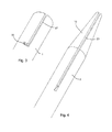
Fig. 3 is a perspective view of the access sheath according to the invention; -
Fig. 4 is a perspective view of the catheter according to the invention; -
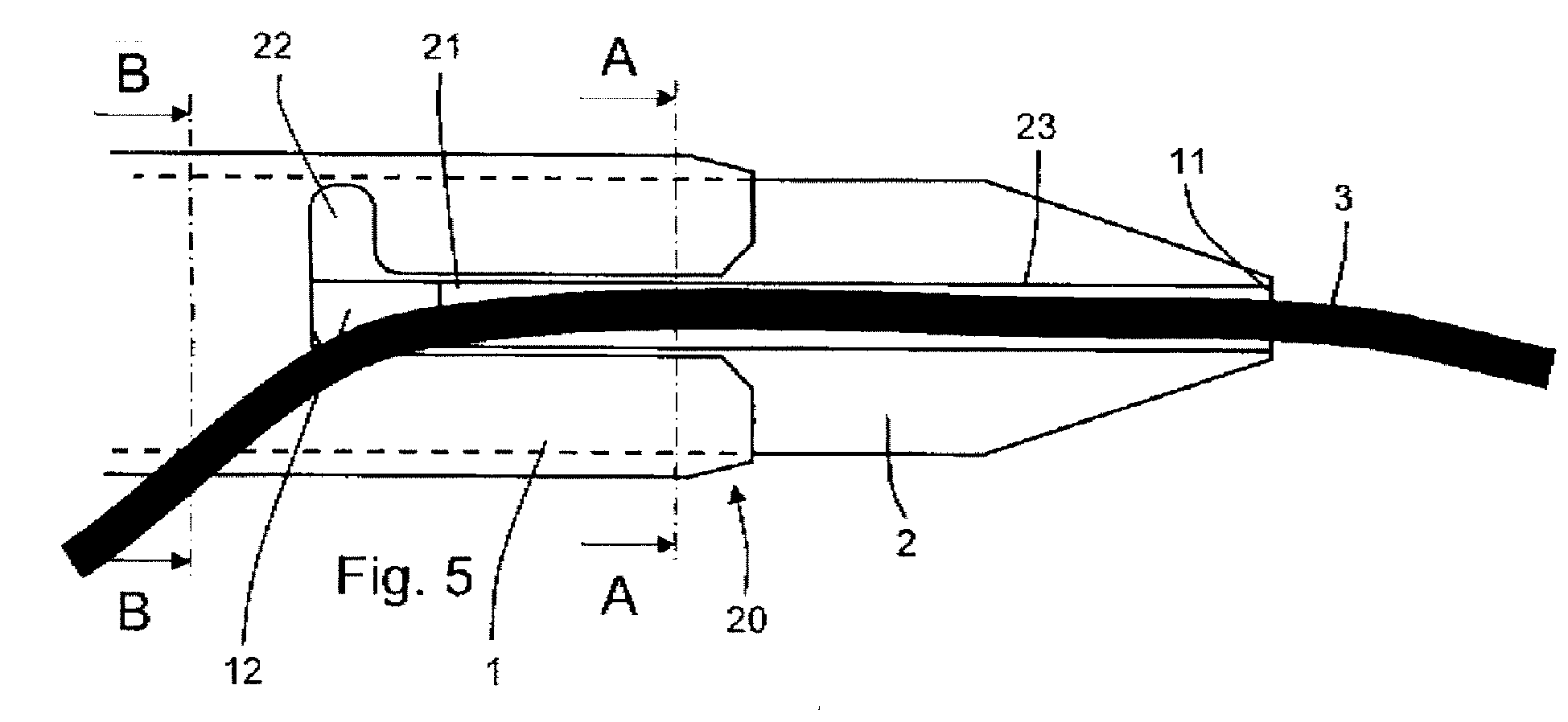
Fig. 5 is a side view of the catheter-access sheath assembly in an open position; -
Fig. 6 is a cross section view along the line A-A of the assembly ofFig. 5 ; -
Fig. 7a shows a first embodiment of a cross section along the line B-B of the assembly ofFig. 5 ; -
Fig. 7b shows a second embodiment of a cross section along the line B-B of the assembly ofFig. 5 ; -
Fig. 8 is a side view of the catheter-access sheath assembly in an closed position; and -
Fig. 9 is a cross section view of the assembly ofFig. 8 . - According to the present invention, the catheter-
access sheath assembly 20 comprises anaccess sheath 1 and acatheter 2. This assembly is foreseen to cooperate with asecurity guide 3. - The
access sheath 1 is provided for accessing to a place to be operated, for example the urinary tract. Theaccess sheath 1 is formed of a reinforced tube 4 that is flexible but resistant to collapse, compression and plication. The access sheath further comprises abucket 5 on its proximal end provided for an easy introduction of instruments and tools. - According to the present invention, the
access sheath 1 comprises alongitudinal opening 21 extending from the distal end of the access sheath. Thisopening 21 is substantially straight over a given length of the access sheath and ends by ashort bend 22 whose function is explained below. - According to a first embodiment, the
catheter 2 is a flexible tube comprising two separate longitudinal hollow channels 61 and 62 both extending between aproximal end 7 and a distal end 8 The distal end 8 is slightly frustoconical in direction of atip 10. According to a second embodiment, thecatheter 2 comprises one hollow channel 61 extending from the proximal end to the distal end. In both embodiments, the catheter further contains agroove 23 extending from thetip 10 of the catheter or close to it over a given length in direction of theproximal end 7 of the catheter. - In the first embodiment, i.e. in the case where the
catheter 2 comprises two hollow channels, thegroove 23 may communicate with one of the hollow channels 62. In the second embodiment, i.e. in the case where thecatheter 2 comprises only one hollow channel 61, thegroove 23 does preferably not communicate with the hollow channel. - The
groove 23 has a width that is sufficiently large to enable an easy insertion and removal of asecurity guide 3. - The
access sheath 1 can move on thecatheter 2 along a longitudinal axis. It can further be rotated on thecatheter 2 around a longitudinal axis between at least two positions. In a first position, called open position and illustrated byFig. 5 and 6 , theopening 21 of theaccess sheath 1 at least partially coincides with thegroove 23 of the catheter and enables the release of thesecurity guide 3. In a second position, called closed position and illustrated byFig. 8 and 9 , theaccess sheath 1 covers thegroove 23 of thecatheter 2 and enables to maintain thesecurity guide 3 within thegroove 23. - In the closed position, the
bend 22 of theopening 21 of the access sheath coincides with thegroove 23 of thecatheter 2. Thus, thesecurity guide 3 can enter thegroove 23 by aninner hole 11 and exits the groove by anouter hole 12 formed by the superposition of thegroove 23 and thebend 22. - According to a preferred embodiment, the
catheter 2 and theaccess sheath 1 comprise a marking 26, 26' indicating the open position, the closed position or both. The marking could also indicate a direction of rotation to move theaccess sheath 1 from the open to the closed position or vice versa. - According to a variant, the
catheter 2 or theaccess sheath 1 may comprise a protrusion (not represented) cooperating with a recess (not represented) in the corresponding part, i.e. either theaccess sheath 1 or thecatheter 2. The protrusion and recess are intended to limit the rotation of theaccess sheath 1 compared to thecatheter 2 to reach the open and closed position. - When the catheter-
access sheath assembly 20 must be used, thesecurity guide 3 is introduced in the place where the operation will take place. For example, the catheter can be positioned up to the urethra, after introduction through the natural entry route, using a cystoscope. - Once the
security guide 3 is positioned, thecatheter 2 is engaged onto theguide 3. More specifically, thesecurity guide 3 is positioned into thegroove 23 of the catheter. Theaccess sheath 1 is placed around the catheter in such a way that theopening 21 of theaccess sheath 1 coincides with thegroove 23 of thecatheter 2. The access sheath is then rotated in order to imprison thesecurity guide 3 in thegroove 23 of the catheter, the access sheath preventing the security guide from leaving this groove. Thesecurity guide 3 exits the access sheath through thebend 22 of theopening 21, which forms theouter hole 12. - The
security guide 3 can be used as a glider to position the catheter-access sheath assembly 20 to operate in a conventional way. When the catheter-access sheath assembly has to be removed, while keeping the security guide in place, theaccess sheath 1 is rotated with regard to thecatheter 2. The access sheath is rotated until the longitudinal part of theopening 21 coincides with thegroove 23 of the catheter. It should be noted that the rotation in closed or open position may be limited by the protrusion and recess on the access sheath and on the catheter. However, it may also be limited only by thesecurity guide 3. In the closed position, the security guide is squeezed between thegroove 23 of the catheter and thebend 22 of theopening 21 of the access sheath. In the open position, thesecurity guide 3 is squeezed between thegroove 23 of thecatheter 2 and the part of theopening 21 opposite to thebend 22. - When the
groove 23 coincides with the longitudinal part of theopening 21, thesecurity guide 3 may exit the groove and it will thus be placed next to the catheter-access sheath assembly. - The present invention works the same way whether the catheter has one or two hollow channels 61, 62. In case it has two channels, one of them ending by the
groove 23, thesecurity guide 3 can be put in place as describe above. One channel is dedicated to the security guide and the other channel can be used for other tasks. In case the catheter has only one channel, it does not interfere with thegroove 23. - Thank to this invention, the material used for manufacturing the catheter does not have to be elastic and the range of usable material is greater. Moreover, the width of the groove and opening does not have to be closely adapted to the diameter of the security guide. The only important thing is that the security guide can be maintained in the groove in closed position and removed from the groove and opening in open position.
Claims (10)
- Catheter-access sheath assembly (20) comprising a catheter (2) and an access sheath (1), said assembly being intended for positioning the access sheath (1) in a working position and a security guide (3) next to the access sheath (1), wherein the access sheath (1) is adapted to be threaded onto the catheter (2), said assembly being characterized in that the catheter (2) comprises at least a groove (23) extending between an outer hole (12) and an inner hole (11), said groove (23) having a greater width than the width of the security guide (3), in that the access sheath (1) comprises an opening (21) extending longitudinally from a distal end of the access sheath (1), in that the access sheath (1) is rotatable around the catheter (2) between an open position in which the opening (21) of the access sheath (1) at least partially coincides with the groove (23) of the catheter and enables the release of the security guide (3), and a closed position in which the access sheath (1) covers the groove (23) of the catheter (2) and enables to maintain the security guide (3) within the groove (23).
- Catheter-access sheath assembly according to claim 1, characterized in that the opening (21) of the access sheath (1) comprises a bend (22) at a proximal end, and in that said bend (22) coincides with the groove (23) in the closed position.
- Catheter-access sheath assembly according to claim 1, characterized in that the catheter (2) and the access sheath (1) comprise at least one marking (26, 26') indicating the open position, said marking being visible while the catheter-access sheath assembly is being used
- Catheter-access sheath assembly according to any of claims 1 to 3, characterized in that the catheter (2) and the access sheath (1) comprise at least one marking (26, 26') indicating the closed position said marking being visible while the catheter-access sheath assembly is being used.
- Catheter-access sheath assembly according to claim 1, characterized in that the access sheath (1) comprises at least one marking (26, 26') indicating the relative rotation direction of the access sheath (1) and of the catheter (2) to reach the open or closed position said marking being visible while the catheter-access sheath assembly is being used.
- Catheter-access sheath assembly according to claim 1, characterized in that the catheter (2) comprises a protrusion cooperating with a recess in the access sheath (1), the protrusion and recess limiting the rotation of the access sheath (1) compared to the catheter (2), to reach the open and closed position.
- Catheter-access sheath assembly according to claim 1, characterized in that the inner hole (11) of the catheter (2) coincides with the distal end of the catheter (2)
- Catheter-access sheath assembly according to claim 1, characterized in that the catheter (2) comprises two hollow channels (61, 62), one of said hollow channels (62) communicating with the groove (23) of the catheter.
- Catheter-access sheath assembly according to claim 1, characterized in that the catheter (2) comprises one hollow channel (61) which do not communicate with the groove (23) of the catheter.
- Method for positioning an access sheath (1) and a security guide (3) next to the access sheath (1), said method using a catheter-access sheath assembly (20) comprising a catheter (2), said catheter (2) comprising a groove (23) and said access sheath (1) comprising an opening (21) extending longitudinally from a distal end of the access sheath (1), said access sheath (1) being rotatable around the catheter (2) between an open position in which the opening (21) of the access sheath (1) at least partially coincides with the groove (23) of the catheter and enables the release of the security guide (3), and a closed position in which the access sheath (1) covers the groove (23) of the catheter (2) and enables to maintain the security guide (3) within the groove (23), said method being characterized in that it comprises the steps of :- positioning the security guide (3) in a place where the security guide (3) will be used;- positioning a portion of the security guide (3) in the groove (23) of the catheter (2);- placing the access sheath (1) onto the catheter (2) in a closed position in such a way that said portion of the security guide (3) is maintained between the catheter (2) and the access sheath (1);- driving the access sheath (1) and the catheter (2) along the security guide (3) to the place where the access sheath (1) will be used;- rotating the access sheath (1) with regard to the catheter (2) to reach the open position in which the security guide (3) exits the groove (23) of the catheter (2);- removing the catheter (2).
Priority Applications (2)
| Application Number | Priority Date | Filing Date | Title |
|---|---|---|---|
| EP13290064.8A EP2777748A1 (en) | 2013-03-15 | 2013-03-15 | Catheter-access sheath assembly and a security guide next to the access sheath |
| US14/205,453 US20140276436A1 (en) | 2013-03-15 | 2014-03-12 | Assembly for positioning a security guide next to an access sheath |
Applications Claiming Priority (1)
| Application Number | Priority Date | Filing Date | Title |
|---|---|---|---|
| EP13290064.8A EP2777748A1 (en) | 2013-03-15 | 2013-03-15 | Catheter-access sheath assembly and a security guide next to the access sheath |
Publications (1)
| Publication Number | Publication Date |
|---|---|
| EP2777748A1 true EP2777748A1 (en) | 2014-09-17 |
Family
ID=48013895
Family Applications (1)
| Application Number | Title | Priority Date | Filing Date |
|---|---|---|---|
| EP13290064.8A Withdrawn EP2777748A1 (en) | 2013-03-15 | 2013-03-15 | Catheter-access sheath assembly and a security guide next to the access sheath |
Country Status (2)
| Country | Link |
|---|---|
| US (1) | US20140276436A1 (en) |
| EP (1) | EP2777748A1 (en) |
Cited By (1)
| Publication number | Priority date | Publication date | Assignee | Title |
|---|---|---|---|---|
| CN108742793A (en) * | 2018-06-07 | 2018-11-06 | 丽水市人民医院 | The special sting device of abdominal operation |
Families Citing this family (4)
| Publication number | Priority date | Publication date | Assignee | Title |
|---|---|---|---|---|
| US11633579B2 (en) * | 2017-03-03 | 2023-04-25 | Sainath Intellectual Properties, Llc | Dilator with slit and slidable sleeve |
| US11471652B2 (en) * | 2018-01-31 | 2022-10-18 | Lake Region Manufacturing, Inc. | Apparatus, system, and method for extending a guidewire |
| CN113616901A (en) * | 2020-05-07 | 2021-11-09 | 巴德阿克塞斯系统股份有限公司 | Enhanced guidewire advancement length |
| WO2026004303A1 (en) * | 2024-06-28 | 2026-01-02 | 朝日インテック株式会社 | Inserter |
Citations (8)
| Publication number | Priority date | Publication date | Assignee | Title |
|---|---|---|---|---|
| DE3347150A1 (en) * | 1983-12-27 | 1985-07-04 | Beiersdorf Ag, 2000 Hamburg | Bladder puncturing set |
| US5667514A (en) * | 1995-12-04 | 1997-09-16 | Cochlear Ltd. | Device and method for inserting a flexible element into soft tissue |
| US20020072712A1 (en) * | 2000-10-12 | 2002-06-13 | Nool Jeffrey A. | Medical wire introducer and protective sheath |
| US20040064147A1 (en) * | 2002-09-30 | 2004-04-01 | Struble Chester L. | Introducer system having a reclosable split sheath for lead replacement |
| US20040143286A1 (en) * | 2003-01-17 | 2004-07-22 | Johnson Eric G. | Catheter with disruptable guidewire channel |
| US20070276288A1 (en) * | 2004-04-05 | 2007-11-29 | Kenneth Khaw | Vascular Access Needle |
| US20090062769A1 (en) * | 2007-04-13 | 2009-03-05 | Boston Scientific Scimed, Inc. | Rapid exchange catheter converter |
| WO2009127216A1 (en) | 2008-04-18 | 2009-10-22 | Coloplast A/S | A method for positioning an access sheath and a security guide, a catheter for positioning an access sheath and a catheter-access sheath assembly |
Family Cites Families (1)
| Publication number | Priority date | Publication date | Assignee | Title |
|---|---|---|---|---|
| DE602004020901D1 (en) * | 2003-07-31 | 2009-06-10 | Wilson Cook Medical Inc | System for the introduction of several medical devices |
-
2013
- 2013-03-15 EP EP13290064.8A patent/EP2777748A1/en not_active Withdrawn
-
2014
- 2014-03-12 US US14/205,453 patent/US20140276436A1/en not_active Abandoned
Patent Citations (8)
| Publication number | Priority date | Publication date | Assignee | Title |
|---|---|---|---|---|
| DE3347150A1 (en) * | 1983-12-27 | 1985-07-04 | Beiersdorf Ag, 2000 Hamburg | Bladder puncturing set |
| US5667514A (en) * | 1995-12-04 | 1997-09-16 | Cochlear Ltd. | Device and method for inserting a flexible element into soft tissue |
| US20020072712A1 (en) * | 2000-10-12 | 2002-06-13 | Nool Jeffrey A. | Medical wire introducer and protective sheath |
| US20040064147A1 (en) * | 2002-09-30 | 2004-04-01 | Struble Chester L. | Introducer system having a reclosable split sheath for lead replacement |
| US20040143286A1 (en) * | 2003-01-17 | 2004-07-22 | Johnson Eric G. | Catheter with disruptable guidewire channel |
| US20070276288A1 (en) * | 2004-04-05 | 2007-11-29 | Kenneth Khaw | Vascular Access Needle |
| US20090062769A1 (en) * | 2007-04-13 | 2009-03-05 | Boston Scientific Scimed, Inc. | Rapid exchange catheter converter |
| WO2009127216A1 (en) | 2008-04-18 | 2009-10-22 | Coloplast A/S | A method for positioning an access sheath and a security guide, a catheter for positioning an access sheath and a catheter-access sheath assembly |
Cited By (1)
| Publication number | Priority date | Publication date | Assignee | Title |
|---|---|---|---|---|
| CN108742793A (en) * | 2018-06-07 | 2018-11-06 | 丽水市人民医院 | The special sting device of abdominal operation |
Also Published As
| Publication number | Publication date |
|---|---|
| US20140276436A1 (en) | 2014-09-18 |
Similar Documents
| Publication | Publication Date | Title |
|---|---|---|
| US9649415B2 (en) | Surgical kits for body cavity drainage and related methods | |
| US9233226B2 (en) | Drainage catheter with pig-tail straightener | |
| EP2777748A1 (en) | Catheter-access sheath assembly and a security guide next to the access sheath | |
| EP3028623B1 (en) | Endoscopic instrument and endoscopic instrument system | |
| US20090318894A1 (en) | Method for positioning an access sheath and a security guide, a catheter for positioning an access sheath and a catheter-access sheath assembly | |
| US11058806B2 (en) | Body cavity drainage devices including drainage tubes having inline portions and related methods | |
| EP2633877B1 (en) | A catheter-access sheath assembly for positioning an access sheath and a security guide | |
| US20150374959A1 (en) | Body cavity drainage devices with locking devices and related methods | |
| US20170281176A1 (en) | Medical clip device, method for producing medical clip device and method for operating thereof | |
| US20090062769A1 (en) | Rapid exchange catheter converter | |
| US20040199048A1 (en) | High flow stone basket system | |
| US11033287B2 (en) | Grasping tool | |
| EP3329858A1 (en) | Tissue recovery tool and tissue recovery system | |
| EP2903494B1 (en) | Disposable endoscopy and biopsy system | |
| EP3618688B1 (en) | Systems and methods for device exchange in an endoscopic procedure | |
| EP2777747B1 (en) | An access sheath | |
| EP2777745B1 (en) | An access sheath | |
| WO2018229219A1 (en) | Carrier of a resectoscope and electrode instrument | |
| EP3238641B1 (en) | Medical instrument | |
| EP2842593A1 (en) | Access sheath | |
| DE102009022867B4 (en) | Minimally invasive medical instrument | |
| EP2842594A1 (en) | Access sheath | |
| WO2015200854A1 (en) | Body cavity drainage devices including drainage tubes having inline portions and related methods | |
| EP2842590A1 (en) | Access sheath |
Legal Events
| Date | Code | Title | Description |
|---|---|---|---|
| PUAI | Public reference made under article 153(3) epc to a published international application that has entered the european phase |
Free format text: ORIGINAL CODE: 0009012 |
|
| 17P | Request for examination filed |
Effective date: 20130315 |
|
| AK | Designated contracting states |
Kind code of ref document: A1 Designated state(s): AL AT BE BG CH CY CZ DE DK EE ES FI FR GB GR HR HU IE IS IT LI LT LU LV MC MK MT NL NO PL PT RO RS SE SI SK SM TR |
|
| AX | Request for extension of the european patent |
Extension state: BA ME |
|
| R17P | Request for examination filed (corrected) |
Effective date: 20150317 |
|
| RBV | Designated contracting states (corrected) |
Designated state(s): AL AT BE BG CH CY CZ DE DK EE ES FI FR GB GR HR HU IE IS IT LI LT LU LV MC MK MT NL NO PL PT RO RS SE SI SK SM TR |
|
| 17Q | First examination report despatched |
Effective date: 20161019 |
|
| STAA | Information on the status of an ep patent application or granted ep patent |
Free format text: STATUS: THE APPLICATION IS DEEMED TO BE WITHDRAWN |
|
| 18D | Application deemed to be withdrawn |
Effective date: 20180605 |