EP2777673A2 - Apparatus and system for turning and positioning a patient - Google Patents
Apparatus and system for turning and positioning a patient Download PDFInfo
- Publication number
- EP2777673A2 EP2777673A2 EP20140159820 EP14159820A EP2777673A2 EP 2777673 A2 EP2777673 A2 EP 2777673A2 EP 20140159820 EP20140159820 EP 20140159820 EP 14159820 A EP14159820 A EP 14159820A EP 2777673 A2 EP2777673 A2 EP 2777673A2
- Authority
- EP
- European Patent Office
- Prior art keywords
- sheet
- bed
- sliding member
- patient
- along
- Prior art date
- Legal status (The legal status is an assumption and is not a legal conclusion. Google has not performed a legal analysis and makes no representation as to the accuracy of the status listed.)
- Granted
Links
- 239000002783 friction material Substances 0.000 claims abstract description 92
- 239000000463 material Substances 0.000 claims description 110
- 238000000034 method Methods 0.000 claims description 71
- 208000004210 Pressure Ulcer Diseases 0.000 description 19
- 239000006261 foam material Substances 0.000 description 14
- 230000002745 absorbent Effects 0.000 description 12
- 239000002250 absorbent Substances 0.000 description 12
- 239000003550 marker Substances 0.000 description 10
- 230000000284 resting effect Effects 0.000 description 10
- 230000008901 benefit Effects 0.000 description 9
- 239000004677 Nylon Substances 0.000 description 7
- 239000000853 adhesive Substances 0.000 description 7
- 230000001070 adhesive effect Effects 0.000 description 7
- 229920001778 nylon Polymers 0.000 description 7
- 238000010008 shearing Methods 0.000 description 7
- 238000000576 coating method Methods 0.000 description 6
- 239000013013 elastic material Substances 0.000 description 6
- 238000005096 rolling process Methods 0.000 description 6
- 239000011248 coating agent Substances 0.000 description 5
- 238000011160 research Methods 0.000 description 5
- 208000027418 Wounds and injury Diseases 0.000 description 4
- 230000006378 damage Effects 0.000 description 4
- 208000014674 injury Diseases 0.000 description 4
- 238000004381 surface treatment Methods 0.000 description 4
- 239000004831 Hot glue Substances 0.000 description 3
- 238000005516 engineering process Methods 0.000 description 3
- 210000004247 hand Anatomy 0.000 description 3
- 238000003780 insertion Methods 0.000 description 3
- 230000037431 insertion Effects 0.000 description 3
- 229920000728 polyester Polymers 0.000 description 3
- 230000002829 reductive effect Effects 0.000 description 3
- 238000005303 weighing Methods 0.000 description 3
- 208000028399 Critical Illness Diseases 0.000 description 2
- 230000009471 action Effects 0.000 description 2
- 230000009286 beneficial effect Effects 0.000 description 2
- 230000000295 complement effect Effects 0.000 description 2
- 238000010276 construction Methods 0.000 description 2
- 239000012530 fluid Substances 0.000 description 2
- 239000006260 foam Substances 0.000 description 2
- 238000004806 packaging method and process Methods 0.000 description 2
- 230000002093 peripheral effect Effects 0.000 description 2
- 230000009467 reduction Effects 0.000 description 2
- 239000000126 substance Substances 0.000 description 2
- 238000012360 testing method Methods 0.000 description 2
- 238000003466 welding Methods 0.000 description 2
- 229920000742 Cotton Polymers 0.000 description 1
- 239000004952 Polyamide Substances 0.000 description 1
- 239000004698 Polyethylene Substances 0.000 description 1
- 239000004721 Polyphenylene oxide Substances 0.000 description 1
- 229920005830 Polyurethane Foam Polymers 0.000 description 1
- 206010068796 Wound contamination Diseases 0.000 description 1
- 230000004888 barrier function Effects 0.000 description 1
- 210000000988 bone and bone Anatomy 0.000 description 1
- 210000000845 cartilage Anatomy 0.000 description 1
- 230000003247 decreasing effect Effects 0.000 description 1
- 230000032798 delamination Effects 0.000 description 1
- 230000001419 dependent effect Effects 0.000 description 1
- 230000002349 favourable effect Effects 0.000 description 1
- 230000036541 health Effects 0.000 description 1
- 230000006872 improvement Effects 0.000 description 1
- 238000012986 modification Methods 0.000 description 1
- 230000004048 modification Effects 0.000 description 1
- 239000005022 packaging material Substances 0.000 description 1
- 239000003973 paint Substances 0.000 description 1
- 230000000737 periodic effect Effects 0.000 description 1
- 239000004033 plastic Substances 0.000 description 1
- 229920003023 plastic Polymers 0.000 description 1
- 229920002647 polyamide Polymers 0.000 description 1
- 229920000570 polyether Polymers 0.000 description 1
- -1 polyethylene Polymers 0.000 description 1
- 229920000573 polyethylene Polymers 0.000 description 1
- 229920000642 polymer Polymers 0.000 description 1
- 239000004810 polytetrafluoroethylene Substances 0.000 description 1
- 229920001343 polytetrafluoroethylene Polymers 0.000 description 1
- 239000011496 polyurethane foam Substances 0.000 description 1
- 230000008092 positive effect Effects 0.000 description 1
- 230000001681 protective effect Effects 0.000 description 1
- 230000002685 pulmonary effect Effects 0.000 description 1
- 230000003014 reinforcing effect Effects 0.000 description 1
- 210000000954 sacrococcygeal region Anatomy 0.000 description 1
- 238000000926 separation method Methods 0.000 description 1
- 210000002832 shoulder Anatomy 0.000 description 1
- 238000005507 spraying Methods 0.000 description 1
- 238000010561 standard procedure Methods 0.000 description 1
- 230000003068 static effect Effects 0.000 description 1
- XLYOFNOQVPJJNP-UHFFFAOYSA-N water Substances O XLYOFNOQVPJJNP-UHFFFAOYSA-N 0.000 description 1
- 238000005493 welding type Methods 0.000 description 1
- 210000000707 wrist Anatomy 0.000 description 1
Images


Classifications
-
- A—HUMAN NECESSITIES
- A61—MEDICAL OR VETERINARY SCIENCE; HYGIENE
- A61G—TRANSPORT, PERSONAL CONVEYANCES, OR ACCOMMODATION SPECIALLY ADAPTED FOR PATIENTS OR DISABLED PERSONS; OPERATING TABLES OR CHAIRS; CHAIRS FOR DENTISTRY; FUNERAL DEVICES
- A61G7/00—Beds specially adapted for nursing; Devices for lifting patients or disabled persons
- A61G7/10—Devices for lifting patients or disabled persons, e.g. special adaptations of hoists thereto
- A61G7/1073—Parts, details or accessories
-
- A—HUMAN NECESSITIES
- A61—MEDICAL OR VETERINARY SCIENCE; HYGIENE
- A61F—FILTERS IMPLANTABLE INTO BLOOD VESSELS; PROSTHESES; DEVICES PROVIDING PATENCY TO, OR PREVENTING COLLAPSING OF, TUBULAR STRUCTURES OF THE BODY, e.g. STENTS; ORTHOPAEDIC, NURSING OR CONTRACEPTIVE DEVICES; FOMENTATION; TREATMENT OR PROTECTION OF EYES OR EARS; BANDAGES, DRESSINGS OR ABSORBENT PADS; FIRST-AID KITS
- A61F13/00—Bandages or dressings; Absorbent pads
- A61F13/15—Absorbent pads, e.g. sanitary towels, swabs or tampons for external or internal application to the body; Supporting or fastening means therefor; Tampon applicators
- A61F13/45—Absorbent pads, e.g. sanitary towels, swabs or tampons for external or internal application to the body; Supporting or fastening means therefor; Tampon applicators characterised by the shape
-
- A—HUMAN NECESSITIES
- A61—MEDICAL OR VETERINARY SCIENCE; HYGIENE
- A61G—TRANSPORT, PERSONAL CONVEYANCES, OR ACCOMMODATION SPECIALLY ADAPTED FOR PATIENTS OR DISABLED PERSONS; OPERATING TABLES OR CHAIRS; CHAIRS FOR DENTISTRY; FUNERAL DEVICES
- A61G7/00—Beds specially adapted for nursing; Devices for lifting patients or disabled persons
- A61G7/001—Beds specially adapted for nursing; Devices for lifting patients or disabled persons with means for turning-over the patient
-
- A—HUMAN NECESSITIES
- A61—MEDICAL OR VETERINARY SCIENCE; HYGIENE
- A61G—TRANSPORT, PERSONAL CONVEYANCES, OR ACCOMMODATION SPECIALLY ADAPTED FOR PATIENTS OR DISABLED PERSONS; OPERATING TABLES OR CHAIRS; CHAIRS FOR DENTISTRY; FUNERAL DEVICES
- A61G7/00—Beds specially adapted for nursing; Devices for lifting patients or disabled persons
- A61G7/05—Parts, details or accessories of beds
- A61G7/0525—Side-bolsters
-
- A—HUMAN NECESSITIES
- A61—MEDICAL OR VETERINARY SCIENCE; HYGIENE
- A61G—TRANSPORT, PERSONAL CONVEYANCES, OR ACCOMMODATION SPECIALLY ADAPTED FOR PATIENTS OR DISABLED PERSONS; OPERATING TABLES OR CHAIRS; CHAIRS FOR DENTISTRY; FUNERAL DEVICES
- A61G7/00—Beds specially adapted for nursing; Devices for lifting patients or disabled persons
- A61G7/05—Parts, details or accessories of beds
- A61G7/057—Arrangements for preventing bed-sores or for supporting patients with burns, e.g. mattresses specially adapted therefor
-
- A—HUMAN NECESSITIES
- A61—MEDICAL OR VETERINARY SCIENCE; HYGIENE
- A61G—TRANSPORT, PERSONAL CONVEYANCES, OR ACCOMMODATION SPECIALLY ADAPTED FOR PATIENTS OR DISABLED PERSONS; OPERATING TABLES OR CHAIRS; CHAIRS FOR DENTISTRY; FUNERAL DEVICES
- A61G7/00—Beds specially adapted for nursing; Devices for lifting patients or disabled persons
- A61G7/10—Devices for lifting patients or disabled persons, e.g. special adaptations of hoists thereto
- A61G7/1025—Lateral movement of patients, e.g. horizontal transfer
- A61G7/1026—Sliding sheets or mats
-
- A—HUMAN NECESSITIES
- A61—MEDICAL OR VETERINARY SCIENCE; HYGIENE
- A61F—FILTERS IMPLANTABLE INTO BLOOD VESSELS; PROSTHESES; DEVICES PROVIDING PATENCY TO, OR PREVENTING COLLAPSING OF, TUBULAR STRUCTURES OF THE BODY, e.g. STENTS; ORTHOPAEDIC, NURSING OR CONTRACEPTIVE DEVICES; FOMENTATION; TREATMENT OR PROTECTION OF EYES OR EARS; BANDAGES, DRESSINGS OR ABSORBENT PADS; FIRST-AID KITS
- A61F13/00—Bandages or dressings; Absorbent pads
- A61F13/15—Absorbent pads, e.g. sanitary towels, swabs or tampons for external or internal application to the body; Supporting or fastening means therefor; Tampon applicators
- A61F2013/15008—Absorbent pads, e.g. sanitary towels, swabs or tampons for external or internal application to the body; Supporting or fastening means therefor; Tampon applicators characterized by the use
- A61F2013/15048—Absorbent pads, e.g. sanitary towels, swabs or tampons for external or internal application to the body; Supporting or fastening means therefor; Tampon applicators characterized by the use for protection against contamination, or protection in using body disinfecting wipes
-
- A—HUMAN NECESSITIES
- A61—MEDICAL OR VETERINARY SCIENCE; HYGIENE
- A61F—FILTERS IMPLANTABLE INTO BLOOD VESSELS; PROSTHESES; DEVICES PROVIDING PATENCY TO, OR PREVENTING COLLAPSING OF, TUBULAR STRUCTURES OF THE BODY, e.g. STENTS; ORTHOPAEDIC, NURSING OR CONTRACEPTIVE DEVICES; FOMENTATION; TREATMENT OR PROTECTION OF EYES OR EARS; BANDAGES, DRESSINGS OR ABSORBENT PADS; FIRST-AID KITS
- A61F13/00—Bandages or dressings; Absorbent pads
- A61F13/15—Absorbent pads, e.g. sanitary towels, swabs or tampons for external or internal application to the body; Supporting or fastening means therefor; Tampon applicators
- A61F2013/15008—Absorbent pads, e.g. sanitary towels, swabs or tampons for external or internal application to the body; Supporting or fastening means therefor; Tampon applicators characterized by the use
- A61F2013/15154—Absorbent pads, e.g. sanitary towels, swabs or tampons for external or internal application to the body; Supporting or fastening means therefor; Tampon applicators characterized by the use for hospitalised patients
Abstract
Description
- The present application claims priority to and is a continuation-in-part of
U.S. Patent Application No. 13/014,497 andU.S. Patent Application No. 13/014,500, both filed January 6, 2011 , both of which applications are incorporated by reference herein in their entireties. - The present invention generally relates to an apparatus, system, and method for turning and positioning a person supine on a bed or the like, and, more particularly, to a sheet having a gripping surface, a slipping surface, an absorbent pad, and/or a wedge for use in turning and positioning a supine person, as well as systems and methods including one or more of such apparatuses.
- Nurses and other caregivers at hospitals, assisted living facilities, and other locations often care for bedridden patients that have limited or no mobility, many of whom are critically ill or injured. These immobile patients are at risk for forming pressure ulcers (bed sores). Pressure ulcers are typically formed by one or more of several factors. Pressure on a patient's skin, particularly for extended periods of time and in areas where bone or cartilage protrudes close to the surface of the skin, can cause pressure ulcers. Frictional forces and shearing forces from the patient's skin rubbing or pulling against a resting surface can also cause pressure ulcers. Excessive heat and moisture can cause the skin to be more fragile and increase the risk for pressure ulcers. One area in which pressure ulcers frequently form is on the sacrum, because a patient lying on his/her back puts constant pressure on the sacrum, and sliding of the patient in a bed can also cause friction and shearing at the sacrum. Additionally, some patients need to rest with their heads inclined for pulmonary reasons, which can cause patients to slip downward in the bed and cause further friction or shearing at the sacrum and other areas. Existing devices and methods often do not adequately protect against pressure ulcers in bedridden patients, particularly pressure ulcers in the sacral region.
- One effective way to combat sacral pressure ulcers is frequent turning of the patient, so that the patient is resting on one side or the other, and pressure is taken off of the sacrum. Pillows that are stuffed partially under the patient are often use to support the patient's body in resting on their left or right sides. A protocol is often used for scheduled turning of bedridden patients, and dictates that patients should be turned Q2, or every two hours, either from resting at a 30° angle on one side to a 30° angle on the other side, or from 30° on one side to 0°/supine (lying on his/her back) to 30° on the other side. However, turning patients is difficult and time consuming, typically requiring two or more caregivers, and can result in injury to caregivers from pushing and pulling the patient's weight during such turning. As a result, ensuring compliance with turning protocols, Q2 or otherwise, is often difficult. Additionally, the pillows used in turning and supporting the patient are non-uniform and can pose difficulties in achieving consistent turning angles, as well as occasionally slipping out from underneath the patient.
- The present invention seeks to overcome certain of these limitations and other drawbacks of existing devices, systems, and methods, and to provide new features not heretofore available.
- The present invention relates generally to systems for turning and positioning persons in a supine position, such as a patient in a hospital bed. Aspects of the invention relate to a device or system for use with a bed having a frame and a supporting surface supported by the frame. The system includes a sheet having a bottom surface adapted to be placed above the supporting surface of the bed and a top surface opposite the bottom surface, and a plurality of tether straps connected to the sheet and extending from the sheet, each tether strap being configured for connection to the bed. The bottom surface is at least partially formed of a first material having a first coefficient of friction, and the top surface is at least partially formed of a second material having a second coefficient of friction, and wherein the second coefficient of friction is higher than the first coefficient of friction such that the top surface provides greater slipping resistance than the bottom surface. The plurality of tether straps include at least first and second pairs of tether straps, the first pair of tether straps connected proximate a top edge of the sheet and the second pair of tether straps connected proximate a bottom edge of the sheet opposite the top edge.
- According to one aspect, the system further includes a wedge having a base wall, a ramp surface, and a back wall, with the ramp surface being positioned at an angle to the base wall. The wedge is configured to be positioned under the sheet such that the base wall confronts the supporting surface of the bed and the ramp surface confronts the bottom surface of the sheet. The wedge may further include a wedge body formed at least partially of a compressible material and defining the base wall, the ramp surface, and the back wall, and the wedge may have a low friction material positioned on the ramp surface and a high friction foam material positioned on the base wall. The high friction foam material is adapted to resist sliding of the base wall with respect to the supporting surface of the bed. The system may further include a second, similarly configured wedge.
- According to another aspect, each tether strap comprises an elastic portion forming at least a portion of a length of the tether strap. Each tether strap may also include a non-elastic portion forming a portion of the length of the tether strap. In this configuration, the elastic portion may be connected at one end to the sheet and at the other end to the non-elastic portion, and the non-elastic portion is configured for connection to the bed. The non-elastic portion may have a hook-and-loop connecting structure configured to permit the non-elastic portion to connect to itself in a loop, such that a connecting member on the bed is received in the loop to connect the tether strap to the bed.
- According to a further aspect, the system may include a fastener configured for attachment to the bed, where the fastener includes an engagement member configured to be engaged by one of the tether straps to connect the tether strap to the bed.
- According to yet another aspect, the system also includes a sliding member formed of a low friction material and connected to the bottom surface of the sheet to assist in lateral sliding of the sheet. The sliding member has a fixed portion that is fixed to the bottom surface of the sheet and a free portion that is moveable over a range of movement with respect to the bottom surface of the sheet along a lateral direction extending between side edges of the sheet. At least a portion of the bottom surface of the sheet is configured to slide against the sliding member within the range of movement of the sliding member when the sheet is moved along the lateral direction. The low friction material of the sliding member may be the same as the first material of the sheet.
- According to still further aspects, the first pair of tether straps are connected to opposed side edges of the sheet proximate the top edge, and the second pair of tether straps are connected to the opposed side edges of the sheet proximate the bottom edge.
- Additional aspects of the invention relate to a device or system for use with a bed having a frame and a supporting surface supported by the frame. The system includes a sheet having a bottom surface adapted to be placed above the supporting surface of the bed and a top surface opposite the bottom surface, and a sliding member formed of a low friction material and connected to the bottom surface of the sheet. The bottom surface of the sheet has a low friction surface forming at least a portion of the bottom surface, and the top surface has a high friction surface forming at least a portion of the top surface, such that the top surface provides greater slipping resistance than the bottom surface. The sheet further has a top edge configured to be positioned proximate a head of the bed, a bottom edge configured to be positioned proximate a foot of the bed, and opposed side edges located between the top and bottom edges. The sliding member has a fixed portion that is fixed to the bottom surface of the sheet and a free portion that is moveable over a range of movement with respect to the bottom surface of the sheet along a lateral direction extending between the side edges. At least a portion of the bottom surface of the sheet is configured to slide against the sliding member within the range of movement of the sliding member when the sheet is moved along the lateral direction, to facilitate lateral movement of the sheet.
- According to one aspect, the sliding member is formed of a sheet of flexible material connected to the bottom surface of the sheet along a longitudinal direction extending between the top and bottom edges. The sheet of flexible sheet material may be formed in a tubular structure, where the tubular structure has a central passage aligned with the longitudinal direction. The sliding member may be connected to the bottom surface of the sheet along at least one connection line extending along the longitudinal direction. For example, the sliding member may be connected to the bottom surface of the sheet along a first connection line and a second connection line spaced from the first connection line, where the first and second connection lines extend along the longitudinal direction.
- According to another aspect, the low friction surface on the bottom surface of the sheet is formed of the same low friction material as the sliding member.
- According to a further aspect, a plurality of tether straps may be connected to the sheet and extend from the sheet, each tether strap being configured for connection to the bed. The plurality of tether straps include at least first and second pairs of tether straps, the first pair of tether straps connected proximate the top edge and the second pair of tether straps connected proximate the bottom edge.
- According to yet another aspect, the system also includes a second sliding member that may have a similar construction to the sliding member described above. The two sliding members may be substantially parallel to each other. The first and second sheets of flexible material may each be formed in a tubular structure having a central passage aligned with the longitudinal direction, such that the central passages of the two sliding members are substantially parallel. Additionally, the sliding member may be connected to the bottom surface of the sheet along at least one first connection line extending along the longitudinal direction, and the second sliding member is connected to the bottom surface of the sheet along at least one second connection line extending along the longitudinal direction, such that the first and second central connection lines are substantially parallel.
- Further aspects of the invention relate to a method of using a system as described above, with a sheet including a plurality of tether straps for connection to the bed. The sheet is placed on the bed, and the straps are connected, then an absorbent pad is placed into contact with the top surface of the sheet, wheree the second material resists sliding of the pad with respect to the top surface, due to the second coefficient of friction being higher. A patient is then positioned above the supporting surface of the mattress, such that the supporting surface supports the patient and at least a portion of the patient rests on the absorbent pad. Both pairs of tether strap are connected to the bed proximate the head of the bed and connecting the second pair of tether straps to the bed proximate the foot of the bed. Additionally, a wedge is placed at least partially underneath the sheet, the wedge having a base wall, a ramp surface positioned at an angle to the base wall to form an apex, and a back wall opposite the apex, by inserting the apex of the wedge underneath an edge of the sheet from the first side of the bed such that the base wall confronts the supporting surface of the mattress and the ramp surface confronts the bottom surface of the sheet. The sheet is then moved toward the back wall of the wedge to slide the patient and at least a portion of the sheet at least partially up the ramp surface of the wedge, such that the ramp surface of the wedge partially supports the patient, to cause the patient to lie in an angled position. A second wedge configured similarly to the original wedge would work as well.
- According to one aspect, each of the tether straps includes an elastic portion forming at least a portion of a length of the tether strap. Each of the tether straps may also include a non-elastic portion forming a portion of the length of the tether strap, where the elastic portion is connected at one end to the sheet and the elastic portion is connected at the other end to the non-elastic portion, and the non-elastic portion is connected to the bed. The non-elastic portion may have a hook-and-loop connecting structure that permits the non-elastic portion to connect to itself in a loop, and each of the tether straps is connected to the bed such that a connecting member on the bed is received in the loop.
- According to another aspect, the method includes connecting a fastener to the bed, wherein the fastener includes an engagement member, and one of the tether straps is connected to the bed by engaging the one of the tether straps the engagement member of the fastener.
- According to a further aspect, the method may utilize a sliding member formed of a low friction material and connected to the bottom surface of the sheet, with the sliding member having a fixed portion that is fixed to the bottom surface of the sheet and a free portion that is moveable over a range of movement with respect to the bottom surface of the sheet along a lateral direction extending between side edges of the sheet. When the sheet is moved toward the back wall of the wedge, at least a portion of the bottom surface of the sheet slides against the sliding member within the range of movement of the sliding member to reduce the friction of the sliding member.
- According to yet another aspect, the first pair of tether straps are connected to opposed side edges of the sheet proximate the top edge, and the second pair of tether straps are connected to the opposed side edges of the sheet proximate the bottom edge. The first pair of tether straps may also be connected to the first and second sides of the bed proximate the head, and the second pair of tether straps are connected to the first and second sides the bed proximate the bottom edge.
- Still further aspects of the invention relate to a method for use with a bed and a sheet as described above. The sheet is placed on the bed, and the sheet includes a sliding member formed of a low friction material connected to the bottom surface of the sheet. The sliding member has a fixed portion that is fixed to the bottom surface of the sheet and a free portion that is moveable over a range of movement with respect to the bottom surface of the sheet along a lateral direction extending between the side edges. The patient is positioned above the supporting surface of the bed, such that at least a portion of the patient rests above the sheet. The first side edge of the sheet is then moved toward the first side of the bed along the lateral direction, such that at least a portion of the bottom surface of the sheet slides against the sliding member within the range of movement of the sliding member when the sheet is moved toward the first side of the bed along the lateral direction.
- According to one aspect, a support device is placed at least partially underneath the sheet, by inserting the support device underneath the first side edge of the sheet from the first side of the bed. Moving the first side edge of the sheet toward the first side of the bed along the lateral direction slides the patient and at least a portion of the sheet at least partially up on top of the support device, such that the support device at least partially supports one side of the patient to cause the patient to lie in an angled position. The sliding member includes a sheet of flexible material connected to the bottom surface of the sheet along a longitudinal direction extending between the top and bottom edges. The sheet of flexible sheet material may be formed in a tubular structure, where the tubular structure has a central passage aligned with the longitudinal direction. The sliding member may be connected to the bottom surface of the sheet along at least one connection line extending along the longitudinal direction.
- According to another aspect, a plurality of tether straps connected to the sheet and extending from the sheet are also connected to the bed. The tether straps include at least first and second pairs of tether straps, where the first pair of tether straps are connected proximate the top edge and the second pair of tether straps are connected proximate the bottom edge.
- According to another aspect, the sheet further includes a second sliding member similar to the first sliding member, which functions in a similar manner when the sheet is moved. Each sliding member may include a sheet of flexible material connected to the bottom surface of the sheet along a longitudinal direction extending between the top and bottom edges, such that the sliding members are substantially parallel to each other. The sliding members may each be formed in a tubular structure with a central passage aligned with the longitudinal direction, such that the central passages of the two sliding members are substantially parallel. Further, each sliding member may be connected to the bottom surface of the sheet along at least one connection line extending along the longitudinal direction, such that the connection lines of the two sliding members are substantially parallel.
- Other features and advantages of the invention will be apparent from the following specification taken in conjunction with the following drawings.
-
-
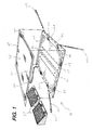
FIG. 1 is an exploded perspective view of one embodiment of a system for use in turning and positioning a patient, according to aspects of the invention; -
FIG. 2 is a top elevation view of a flexible sheet of the system ofFIG. 1 ; -
FIG. 3 is a bottom perspective view of the flexible sheet ofFIG. 2 , with hands illustrating gripping of the flexible sheet; -
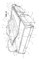
FIG. 4 is a top perspective view of a wedge of the system ofFIG. 1 ; -
FIG. 5 is a bottom perspective view of the wedge of the system ofFIG. 1 ; -
FIG. 6 is a perspective view of the system ofFIG. 1 positioned on a bed; -
FIGS. 7a-d are a sequential series of views illustrating a method of placing the flexible sheet and an absorbent pad of the system ofFIG. 1 on a bed; -
FIGS. 8a-d are a sequential series of views illustrating a method of removing and replacing the absorbent pad ofFIGS. 7a-d on the bed; -
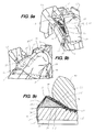
FIGS. 9a-c are a sequential series of views illustrating a method of turning a patient to an angled resting position utilizing the system ofFIG. 1 , according to aspects of the invention; -
FIGS. 10a-c are a sequential series of views illustrating a cross-section of a portion of the system ofFIG. 6 during lateral movement on the bed; -
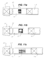
FIGS. 11a-c are a sequential series of views illustrating stretching of a tether strap of the system ofFIG. 1 ; -
FIG. 12 is a front view of a fastener that is usable with the tether straps of the system ofFIG. 1 ; and -
FIG. 13 is a perspective view of the fastener ofFIG. 12 used to connect a tether strap of the system ofFIG. 1 to the bed. - While this invention is susceptible of embodiment in many different forms, there are shown in the drawings, and will herein be described in detail, preferred embodiments of the invention with the understanding that the present disclosure is to be considered as an exemplification of the principles of the invention and is not intended to limit the broad aspects of the invention to the embodiments illustrated and described.
- In general, the invention relates to one or more apparatuses or devices, including a sheet having a high friction or gripping surface and a low friction or slipping surface, an absorbent body pad configured to be placed over the sheet, and one or more wedges configured to be placed underneath the sheet to support the patient in an angled position, as well as systems including one or more of such devices and methods utilizing one or more of such systems and/or devices. Various embodiments of the invention are described below.
- Referring now to the figures, and initially to
FIGS. 1-6 , there is shown an exemplary embodiment of asystem 10 for use in turning and positioning a person in a supine position, such as a patient lying on a hospital bed. As shown inFIG. 1 , thesystem 10 includes asheet 20, anabsorbent body pad 40 configured to be placed over thesheet 20, and one ormore wedges 50 configured to be placed under thesheet 20. The patient can be positioned on top of thebody pad 40, with thebody pad 40 lying on thesheet 20, and one ormore wedges 50 optionally positioned underneath thesheet 20. - As shown in
FIG. 6 , thesystem 10 is configured to be placed on abed 12 or other support apparatus for supporting a person in a supine position. Thebed 12 generally includes aframe 14 and a supportingsurface 16 supported by theframe 14, as shown inFIG. 6 , and has ahead 13, afoot 17 opposite thehead 13, and opposed sides oredges 19 extending between thehead 13 and thefoot 17. The supportingsurface 16 can be provided by amattress 18 or similar structure, and in various embodiments, themattress 18 can incorporate air pressure support, alternating air pressure support and/or low-air-loss (LAL) technology. These technologies are known in the art, and utilize a pump motor or motors (not shown) to effectuate airflow into, over and/or through themattress 18. The air aids in supporting the patient, and the top of themattress 18 may be breathable so that the airflow can pull heat and moisture vapor away from the patient. Thebed 12 may also include one or more bed sheets 15 (such as a fitted sheet or flat sheet), as shown inFIGS. 9a-c and10a-c , as well as pillows, blankets, additional sheets, and other components known in the art. Further, thebed 12 may be an adjustable bed, such as a typical hospital-type bed, where the head 13 (or other parts) of thebed 12 can be raised and lowered, such as to incline the patient's upper body. It is understood that thesystem 10 and the components thereof can be used with other types ofbeds 12 as well. - An example embodiment of the
sheet 20 is shown in greater detail inFIGS. 2-3 . In general, thesheet 20 is flexible and foldable, and has atop surface 21 and abottom surface 22 defined by a plurality ofperipheral edges 23. Thesheet 20 is configured to be positioned on thebed 12 so that thebottom surface 22 is above the supportingsurface 16 of thebed 12 and faces or confronts the supportingsurface 16, and is supported by the supportingsurface 16. As used herein, "above," "below," "over," and "under" do not imply direct contact or engagement. For example, thebottom surface 22 being above the supportingsurface 16 means that that thebottom surface 22 may be in contact with the supportingsurface 16, or may face or confront the supportingsurface 16 and/or be supported by the supportingsurface 16 with one or more structures located between thebottom surface 22 and the supportingsurface 16, such as abed sheet 15 as described above. Likewise, "facing" or "confronting" does not imply direct contact or engagement, and may include one or more structures located between the surface and the structure it is confronting or facing. - As seen in
FIGS. 2-3 , thesheet 20 in this embodiment is rectangular, having fourperipheral edges 23, but could be a different shape in other embodiments. Thetop surface 21 has at least a portion formed of a high-friction or grippingmaterial 24, and thebottom surface 22 has at least a portion formed of a low-friction or slidingmaterial 25. In this embodiment, the sheet includes afirst piece 26 of sheet material that is formed partially or entirely of the low-friction material 25, with asecond piece 27 of sheet material that is formed partially or entirely of the high-friction material 24, with thesecond piece 27 connected to thefirst piece 26 in a surface-to-surface, confronting relation to form a layered structure. As illustrated inFIGS. 2-3 , thefirst piece 26 is larger than thesecond piece 27, so that thefirst piece 26 forms theentire bottom surface 22 of thesheet 20, and thesecond piece 27 forms at least a majority portion of thetop surface 21, with the edges of thesecond piece 27 being recessed from theedges 23 of thesheet 20. In other words, in this embodiment, thesheet 20 is primarily formed by thefirst piece 26, with thesecond piece 27 connected to thefirst piece 26 to form at least a part of thetop surface 21. In another embodiment, thefirst piece 26 forms at least a majority portion of thebottom surface 22, and thesecond piece 27 forms at least a majority portion of thetop surface 21. Thepieces friction material 25 and/or the high-friction material 24 may be formed by multiple pieces in other embodiments. For example, thefirst piece 26 made of the low-friction material 25 may have a plurality of strips or patches of the high-friction material 24 connected on thetop surface 21 in one embodiment. In a further embodiment, thehigh friction material 24 may be or include a coating applied to thelow friction piece 26, such as a spray coating. In yet another embodiment, the high-friction material 24 may be formed of a directional glide material that permits gliding freely in one direction, such as toward thehead 13 of thebed 12, and resists gliding in the opposite direction, such as toward thefoot 17 of thebed 12. For example, a directional glide material may be formed by a stitched material with a directional stitching pattern or a material having a directionally oriented texture, such as by having a ridged or other textured structure. It is understood that a confronting surface (e.g., the underside of the pad 40) may have a complementary material that works with the directional glide material to limit sliding in one direction. As described in greater detail below, the low-friction material 25 permits sliding of thesheet 20 in contact with the supportingsurface 16 of thebed 12, which may include a fittedbed sheet 15 or other sheet, and the high-friction material 24 provides increased resistance to slipping or sliding of the patient and/or thebody pad 40 on which the patient may be lying, in contact with thesheet 20. - As shown in the embodiment in
FIGS. 1-6 , thefirst piece 26 is made substantially entirely of the low-friction material 25. In one embodiment, the low-friction material 25 is at least partially made from polyester and/or nylon (polyamide), although other materials can be used in addition to or instead of these materials. In one embodiment, thehigh friction material 24 is a warp knit tricot material that may be brushed, napped, and/or sanded to raise its pile, which can enhance comfort, and may be made of polyester and/or another suitable material. The material 24 can then be treated with a high friction substance, such as a hot melt adhesive or appropriate plastic, which can be applied as a discontinuous coating to promote breathability. The material 24 can also be treated with a water repellant, such as PTFE. In other embodiments, the high-friction material 24 may include any combination of these components, and may contain other components in addition to or instead of these components. Additionally, both the first andsecond pieces - Generally, the
high friction material 24 has a coefficient of friction that is higher than the coefficient of friction of thelow friction material 25. In one embodiment, the coefficient of friction for thehigh friction material 24 is about 8-10 times higher than the coefficient of friction of thelow friction material 25. In another embodiment, the coefficient of friction for thehigh friction material 24 is between 5 and 10 times higher, or at least 5 times higher, than the coefficient of friction of thelow friction material 25. The coefficient of friction, as defined herein, can be measured as a direct proportion to the pull force necessary to move either of thematerials high friction material 24 is about 8-10 times greater than the pull force for thelow friction material 25, with the same contact material and normal loading, the coefficients of friction will also be 8-10 times different. It is understood that the coefficient of friction may vary by the direction of the pull force, and that the coefficient of friction measured may be measured in a single direction. For example, in one embodiment, the above differentials in the coefficients of friction of thehigh friction material 24 and thelow friction material 25 may be measured as the coefficient of friction of thelow friction material 25 based on a pull force normal to the side edges 23 (i.e. proximate the handles 28) and the coefficient of friction of thehigh friction material 24 based on a pull force normal to the top and bottom edges 23 (i.e. parallel to the side edges 23). - Additionally, the coefficient of friction of the interface between the high-
friction material 24 and thepad 40 is greater than the coefficient of friction of the interface between thelow friction material 25 and thebed sheet 15 or supportingsurface 16. It is understood that the coefficients of friction for the interfaces may also be measured in a directional orientation, as described above. In one embodiment, the coefficient of friction for the interface of thehigh friction material 24 is about 8-10 times higher than the coefficient of friction of the interface of thelow friction material 25. In another embodiment, the coefficient of friction for the interface of thehigh friction material 24 is between 5 and 10 times higher, or at least 5 times higher, than the coefficient of friction of the interface of thelow friction material 25. It is understood that the coefficient of friction for the interface could be modified to at least some degree by modifying factors other than thesheet 20. For example, a high-friction substance or surface treatment may be applied to the bottom surface 44 of thepad 40, to increase the coefficient of friction of the interface. An example of a calculation of the coefficients of friction for these interfaces is described below, including a rip-stop nylon material as thelow friction material 25 and a warp knit tricot material that was brushed, napped, and/or sanded and treated with a hot melt adhesive as thehigh friction material 24. - A 20" x 20" section of bed linen (60% cotton, 40% polyester, 200 threads/inch) was taped without slack to a table top. A 10" x 10" section of blue ripstop nylon was placed on top of the section of bed linen, then a 5 lb., 8" diameter weight was centered on top of the ripstop nylon. A force gauge (Extech 475044, 44 lb.max, digital) was attached to the ripstop nylon and was used to pull/slide the weighted ripstop nylon across the surface of the bed linen. The peak force to slide was recorded. Similarly, a 20" x 20" section of tricot (warp knit tricot material that was brushed, napped, and/or sanded and treated with a hot melt adhesive) was taped without slack to a table top. A 10" x 10" section of an absorbent body pad was placed on top of the section of the tricot material (patient side facing up), then the 5 lb., 8" diameter weight was centered on top of the body pad. The force gauge was attached to the body pad and was used to pull/slide the weighted body pad across the surface of the tricot material. The peak force to slide was recorded. The table below illustrates the results.
Data Point Pull Force (lb) to Induce Sliding (Material A / Material B) Ripstop Nylon / Bed Linen Body Pad / Tricot Material 1 1.68 13.74 2 1.56 13.85 3 1.50 12.91 4 1.43 12.86 5 1.55 13.14 6 1.67 12.63 Ave 1.57 13.19 SD 0.10 0.50 - As illustrated by the above data, the average pulling force required was approximately 8.4 times greater for the underpad-tricot interface than for the ripstop nylon-bed linen interface. Dividing the average required pull force by the 51b normal force gives a coefficient of friction for the interface of ripstop nylon-bed linen of 0.314 and a coefficient of friction for the interface of underpad-tricot of 2.638, which is approximately 8.4 times higher than the coefficient of friction for the ripstop nylon-bed linen interface.
- In the embodiment of
FIGS. 1-6 , thesheet 20 also includes one or more slidingmembers 80 connected to thebottom surface 22 of thesheet 20, which is/are configured to assist with lateral sliding of thesheet 20 across the supportingsurface 16 of thebed 12. The sliding member(s) 80 of the embodiment ofFIGS. 1-6 and their functioning are shown in closer detail inFIGS. 10a-c . In one embodiment, the sliding member has a fixedportion 81 that is fixed to thebottom surface 22 of thesheet 20 at one or more connection points 83 and afree portion 82 that is moveable over a range of movement with respect to thebottom surface 22 of thesheet 20 along a lateral direction L extending between the side edges 23 of thesheet 20 and/or between thesides 19 of thebed 12. The lateral direction of movement L as shown inFIGS. 2 and10a-c is parallel to thetop edge 23 and perpendicular to the side edges 23 of thesheet 20. At least a portion of thebottom surface 22 of thesheet 20 is configured to slide against the slidingmember 80 within the range of movement of the sliding member when thesheet 20 is moved along the lateral direction L, as described in greater detail below. - The sliding
member 80 may be at least partially formed of a low-friction material that has a lower coefficient of friction than thehigh friction material 24, in order to facilitate sliding of the slidingmember 80, and in one embodiment, the slidingmember 80 may be made of the samelow friction material 25 used for thesheet 20. In this configuration, thebottom surface 22 of thesheet 20 slides more easily against the slidingmember 80 than against the confronting surface of thebed 12, which reduces the force necessary to slide thesheet 20 in the lateral direction L, at least within the range of movement of the slidingmember 80. This reduced coefficient of friction may be particularly useful for assisting in overcoming inertial and/or static friction resistance to initial movement of thesheet 20. The low friction material of the slidingmember 80 may also have a lower coefficient of friction than the confronting surface of thebed 12, such as thebed sheet 15, in one embodiment. In another embodiment, the slidingmember 80 may have a lower coefficient of friction on at least one surface as compared to at least one other surface thereof. For example, in atubular sliding member 80 as shown inFIGS. 1-6 and10a-c , the inner surfaces of the sliding member may have a lower coefficient of friction than the outer surfaces (i.e., the surfaces that contact the confronting surface of thebed 12. This configuration further aids sliding of thebottom surface 22 of thesheet 20 against the inner surfaces of the slidingmember 80. The outer surfaces of the slidingmember 80 may have a higher coefficient of friction than the inner surfaces, and may have a coefficient of friction that is higher than that of the confronting surface of thebed 12 in one embodiment. In this configuration, lateral sliding of thebottom surface 22 of thesheet 20 against the low-friction inner surfaces of the slidingmember 80 is facilitated, while the higher-friction outer surfaces resist sliding of thesheet 20 in the longitudinal direction. Such differences in frictional properties between the opposing surfaces may be accomplished by the use of laminate construction, coatings, different stitching patterns, surface treatments and textures, and other techniques. The slidingmembers 80 are positioned proximate the area where the center of mass of the patient would be, in order to provide friction resistance in one of the highest friction areas of thesystem 10. Further, in one embodiment, the slidingmember 80 is configured such that the range of movement of the slidingmember 80 in the longitudinal direction (i.e. between the top andbottom edges 23 and/or between thehead 17 andfoot 19 of thebed 12 when positioned as shown inFIG. 6 ) is significantly smaller than the range of movement in the lateral direction L, and in some configurations, the range of movement in the longitudinal direction may be minimal. Accordingly, the slidingmember 80 provides little or no assistance in moving thesheet 20 in the longitudinal direction, and does not encourage thesheet 20 to slide toward thefoot 19 of thebed 12 when placed under a patient in an inclined position. Further, as described above, the slidingmember 80 may have a higher-friction outer surface that resists sliding in the longitudinal direction. - In the embodiment of
FIGS. 1-6 and10a-c , thesheet 20 includes two slidingmembers 80 that are positioned in substantially parallel and spaced relation on thebottom surface 22 of thesheet 20. Each of the slidingmembers 80 is a piece of flexible sheet material or other flexible material connected to thebottom surface 22 of the sheet at one or more connection points 83. As described above, the flexible material may also be a low friction material. In the embodiment ofFIGS. 1-6 and10a-c , each of the slidingmembers 80 is an 8-inch wide piece of sheet material connected to thesheet 20 at two linear connection points 83 that are 4 inches apart, and each of the connection points 83 is a line extending longitudinally (i.e., in a direction between the top and bottom edges 23), formed by stitching. The slidingmember 80 may be connected to thesheet 20 by additional or alternate methods in other embodiments, including by use of bonding materials, various types of welding, fasteners, and other connection techniques. The linear connection points 83 for the individual slidingmember 80 are parallel to each other and also parallel to the linear connection points 83 of the other slidingmember 80, in this embodiment. It is noted that the ends of the sheet material of the slidingmember 80 are connected at the connection points 83 in this embodiment, however in other configurations, the connection points 83 may be connected inward from the ends, and may leave loose ends that may or may not also be connected to thesheet 20. Additionally, in the embodiment ofFIGS. 1-6 and10a-c , each slidingmember 80 is formed as a loop or tube of material that has two fixedportions 81 connected at the two connection points/lines 83. Thecentral passage 85 of each tube-shaped slidingmember 80 is aligned with the longitudinal direction, and thepassages 85 of the two slidingmembers 80 are substantially parallel to each other. In this configuration, when force is applied to move thesheet 20 along the lateral direction L, the portions of thebottom surface 22 of thesheet 20 located around the slidingmember 80 slide against theloop sliding member 80, reducing the friction during movement, as shown inFIGS. 10a-c and described in greater detail below. It is understood that when the slidingmember 80 is a loop of material, portions of the inner surface of the slidingmember 80 may also slide against itself. In another embodiment (not shown), the sliding member may instead be configured as a loose flap of material having a fixed portion connected at a connection point (which may be linear and longitudinal) and a free portion extending from the connection point. In other embodiments, thesheet 20 may include a greater or smaller number of slidingmembers 80, and may include slidingmembers 80 that are differently configured and/or positioned. For example, in one embodiment, thesheet 20 may include one or more slidingmembers 80 configured to assist movement in the longitudinal direction or in one or more other directions. It is understood that a slidingmember 80 configured for assisting movement in another direction may be oriented substantially perpendicular to such direction. For example, for assisting movement in the longitudinal direction, the slidingmember 80 may be rotated 90° from the orientation depicted inFIGS. 1-6 , so that the slidingmember 80 extends in the lateral direction L, rather than the longitudinal direction. - The sliding
member 80 has a range of movement in the lateral direction L with respect to thebottom surface 22 of thesheet 20 that is dependent upon the lateral width of the slidingmember 80. The range of movement may alternately be expressed as the maximum distance that a point on thesheet 20 can move without any sliding occurring between the slidingmember 80 and the confronting surface of thebed 12, or in other words, the maximum distance that thesheet 20 and the slidingmember 80 can slide against each other.FIGS. 10a-c illustrate the range of movement of the slidingmember 80 of the embodiment inFIGS. 1-6 .FIG. 10a illustrates the maximum leftward position of thesheet 20 with respect to the slidingmember 80, and any further leftward movement will result in sliding of the slidingmember 80 against thebed sheet 15.FIG. 10c likewise represents the maximum rightward position of thesheet 20 with respect to the slidingmember 80, and any further rightward movement will result in sliding of the slidingmember 80 against thebed sheet 15. In the embodiment ofFIGS. 1-6 and10a-c , both slidingmembers 80 have similar or identical ranges of movement, and in another embodiment, two or more slidingmembers 80 may have different ranges of movement. The range of movement of the slidingmember 80 is the distance that thesheet 20 moves between the position inFIG. 10a and the position inFIG. 10c. FIG. 10b illustrates a midpoint between the two extremes ofFIGS. 10a and 10c . The range of movement R of the slidingmember 80 in the embodiment ofFIGS. 1-6 and10a-c (a loop connected to the bottom surface of thesheet 20 at two connection points 83) may be defined or estimated using the following equation:
where W represents the total lateral width of material between the two connection points 83 (which is the total width of the material if connected at the ends), and where D represents the distance between the two connection points 83. In the embodiment ofFIGS. 1-6 and10a-c , where the lateral width W of the material of the slidingmember 80 is 8 inches and the spacing D between the connection points 83 is 4 inches, the total range of motion R is 4 inches. It is noted that a loop of material connected along a single stitching line would be considered to be connected at two points separated by D=0. In another embodiment, where the slidingmember 80 is a flap connected at a single connection point, the range of movement R is equal to twice the lateral width W of the flap. - Additionally, each sliding
member 80 provides an area of contact between thelow friction material 25 of thesheet 20 and the low friction material of the sliding member 80 (and contact of the low friction material of the slidingmember 80 upon itself) that has a lateral width A corresponding to the equation A = (W + D)/2. For example, in the embodiment ofFIGS. 1-6 and10a-c , where the lateral width W of the material of the slidingmember 80 is 8 inches and the spacing D between the connection points 83 is 4 inches, the total width A of the area of contact is 6 inches. The total area of contact would equal the width multiplied by the longitudinal length of the slidingmember 80 in this embodiment. Increased area of contact between the low friction materials may further reduce the force necessary for initial movement. - In the embodiment of
FIGS. 1-6 , thesheet 20 also includes a plurality of elongated tether straps 30 connected to thesheet 20 and extending from thesheet 20 to connect to thebed 10 to secure thesheet 20 in place. As shown inFIG. 6 , the tether straps 30 are connected to the side edges 23 of thesheet 20 and extend to connect thestrap 30 to thebed 12, such as by connection to aconnection member 31 on thebed 12. Theconnection member 31 may be an existing structure on thebed 12, such as brackets/slots for fastening of restraints or strapping down themattress 18, as illustrated inFIG. 6 , or may alternately be aseparate fastener 36 connected to thebed 12 to create a connection member for one ormore straps 30, as described below. Thestraps 30 are configured for being releasably connected to thebed 12, and may include a releasable connectingstructure 33, such as a hook-and-loop connecting structure as shown inFIGS. 1-3 and6 , as well as other types of releasable or non-releasable connections, e.g., clips, hooks, clasps, buckles, ties, etc. Additionally, the hook andloop connecting structure 33 allows for adjustability in the tightness of the connection of thestrap 30 to thebed 12. In another embodiment, thestraps 30 may include a different type of adjustable connectingstructure 33, such as an adjustable buckle. In a further embodiment, two ormore straps 30 may connect to each other, such as by clips, hooks, buckles, clasps, ties, etc., to connect thestraps 30 to thebed 12. - The
sheet 20 in the embodiment ofFIGS. 1-6 includes four tether straps 30. A first pair ofstraps 30 extends from the left andright sides 23 of thesheet 20 proximate thetop edge 23 of thesheet 20, which are configured for connection to thesides 19 of thebed 12 proximate thehead 13. A second pair ofstraps 30 extends from the left andright sides 23 of thesheet 20 proximate thebottom edge 23 of thesheet 20, which are configured for connection to thesides 19 of thebed 12 proximate thefoot 17. Thestraps 30 shown inFIG. 6 may alternately connect to a different area on thebed 12, such as thehead 13 and/or thefoot 17. In other embodiments, thesheet 20 may contain a different number ofstraps 30 and/or may contain straps in additional or different locations from the locations shown inFIGS. 1 and6 . For example, thestraps 30 illustrated inFIGS. 1-6 are located near, but not at, the corners of thesheet 20, and in another embodiment, at least some of thestraps 30 may be located at the corners, or on the top and/orbottom edges 23 of thesheet 20 near the corners. As another example, thesheet 30 may include a single tether strap, and/or the one or more tether straps 30 may have elastic and non-elastic portions that are releasably connected to each other (e.g., via hook-and-loop structure), as shown and described in parentU.S. Patent Application No. 13/014,497 andU.S. Patent Application No. 13/014,500 . - In the configuration shown in
FIGS. 1-3 and6 , thestraps 30 proximate thehead 13 of thebed 12 assist in resisting slipping of thesheet 20 toward thefoot 17 of thebed 12, which tends to occur particularly when thehead 13 of thebed 12 is inclined. It is understood that some degree of downward slippage may occur, and caregivers may "boost" thesheet 20 toward thehead 13 of thebed 12 to counteract past slippage. Thestraps 30 proximate thefoot 17 of thebed 12 assist in preventing "over-boosting" and in keeping thesheet 20 in the proper position on thebed 12. Over-boosting can create additional and unnecessary shear forces on the patient and/or can make the patient more likely to slip downward on thebed 12. In further embodiments, thesheet 20 may not include thestraps 30 at the bottom of thesheet 20, or thesheet 20 may not include thestraps 30 near the top of thesheet 20. - Each
strap 30 may be made from a single piece or multiple pieces. In the embodiment ofFIGS. 1-6 , eachstrap 30 includes anelastic portion 32 that is flexible and stretchable and anon-elastic portion 34 that has little to no stretchability. Theelastic portion 32 may be made from an elastic material that allows a stretch ratio of about 2-3 times its initial length in one embodiment, or may be made from other elastic materials in another embodiment. The elastic andnon-elastic portions strap 30, as shown inFIGS. 1-3 and6 , and are connected at proximate ends. As shown inFIGS. 1-3 and6 , theelastic portion 32 is stitched to thesheet 20, and thenon-elastic portion 34 is stitched to the free end of theelastic portion 32 and is connected to the connectingstructure 33 for connection to thebed 12. In one embodiment, thenon-elastic portion 34 may include a hook-and-loop connecting structure 33, which includes a patch of hook material and a patch of loop material. In another embodiment, thenon-elastic portion 34 may include only a patch of hook material and may be formed of a material that is able to constitute a loop structure to form a hook-and-loop connection for the connectingstructure 33. As shown inFIG. 6 , thenon-elastic portion 34 can be looped through theconnection member 31 on thebed 12, and then attached to itself using the hook-and-loop connecting structure 33, such that theconnection member 31 on thebed 12 is received in the loop to connect thetether strap 30 to thebed 12. Once connected to thebed 12, thestraps 30 resist or thesheet 20 from sliding downward or otherwise out of position, particularly when thehead 13 of thebed 12 is inclined. Theelastic portion 32 provides for slight freedom of movement in this situation. In one embodiment, thestraps 30 near thetop edge 23 of thesheet 20 may have a longerelastic portion 32 as compared to thestraps 30 near thebottom edge 23 of thesheet 20, which gives the top straps 30 a slightly larger degree of stretching and movement. Further, thereleasable connecting structure 33 on eachstrap 30 permits easier disconnection of the tether straps 30 for circumstances in which it is necessary to disconnect thestraps 30 to move or reposition the patient, as the connection member(s) 31 on thebed 12 may not be able to be repositioned. In one embodiment, where thehead 13 of thebed 12 can be raised and lowered, anystraps 30 near thehead 13 may be connected toconnection members 31 that raise and lower with thehead 13, so thestraps 30 do not need to be disconnected in order to raise thehead 13. In alternate embodiments, thestraps 30 may each be made entirely of an elastic material or a non-elastic material, may have additional portions made of additional materials, or may have multiple portions made of an elastic material, non-elastic material, and/or other material. - The
elastic portions 32 of thestraps 30 as shown inFIGS. 1-3 and6 permit the straps to be fastened tightly to thebed 12, while still maintaining some elasticity to permit some degree of movement of thesheet 20. Fastening thestraps 30 too tightly may reduce this freedom of movement, and fastening thestraps 30 too loosely may leave too much freedom of movement. It is understood that some freedom of movement may be necessary in order to insert awedge 50 underneath thesheet 20, as shown inFIGS. 9a-c and described below. In one embodiment, theelastic portion 32 of eachtether strap 30 may have anindicator 35 that indicates the appropriate amount of stretching of theelastic portion 32 during fastening to reach the desired tautness or tightness of thestrap 30, as illustrated inFIGS. 11a-c . Theindicator 35 in this embodiment is formed by a marking (e.g., paint, dye, ink, etc.) on theelastic portion 32 in the shape of a rectangle that expands in width as theelastic portion 32 is stretched.FIG. 11a illustrates the appearance of theindicator 35 when thestrap 30 is not stretched, giving the indicator 35 a rectangular appearance with a small width.FIG. 11b illustrates the appearance of theindicator 35 when theelastic portion 32 is stretched to an appropriate amount, giving the indicator 35 a square shape to indicate the correct tightness.FIG. 11c illustrates the appearance of theindicator 35 when theelastic portion 32 is stretched too far, giving the indicator 35 a rectangular appearance with a large width. In other embodiments, thestrap 30 may use a different type ofindicator 35. Theelastic portions 32 of thestraps 30 also provide some freedom of movement for caregivers to lift the side edges 23 of thesheet 20, e.g., for lifting and/or moving the patient, for insertingwedges 50 or other support devices beneath thesheet 20, etc. Ensuring that thestraps 20 have the appropriate tautness ensures that this freedom of movement is sufficiently provided. - The
sheet 20 may also include one ormore handles 28 to facilitate pulling, lifting, and moving thesheet 20. As shown inFIGS. 2-3 , thesheet 20 hashandles 28 formed bystrips 29 of a strong material that are stitched in periodic fashion to thebottom surface 22 at or aroundopposite edges 23 of thesheet 20. The non-stitched portions can be separated slightly from thesheet 20 to allow a user'shands 76 to slip underneath, and thereby form thehandles 28, as shown inFIG. 3 . Other types of handles may be utilized in other embodiments. - In further embodiments, the
sheet 20 and the components thereof may have different configurations, such as being made of different materials or having different shapes and relative sizes. For example, in one embodiment, the low-friction material 25 and the high-friction material 24 may be made out of pieces of the same size. In another embodiment, the low-friction material 25 and the high-friction material 24 may be part of a single piece that has a portion that is processed or treated to create a surface with a different coefficient of friction. As an example, a single sheet of material could be treated with a non-stick coating or other low-friction coating or surface treatment on one side, and/or an adhesive or other high-friction coating or surface treatment on the other side. Still other embodiments are contemplated within the scope of the invention. - In an alternate embodiment, the
sheet 20 may not utilize a high friction surface, and instead may utilize a releasable connection to secure thepad 40 in place with respect to thesheet 20. For example, thesheet 20 andpad 40 may include complementary connections, such as hook-and-loop connectors, buttons, snaps, or other connectors. In another alternate embodiment, thesheet 20 may not utilize astrap 30, and may resist sliding in another way. In a further embodiment, thesheet 20 may be used without apad 40, with the patient directly in contact with thetop surface 21 of the sheet, and the high-friction material 24 can still resist sliding of the patient on thesheet 20. - The
sheet 20 may further include apositioning marker 84 to assist in properly positioning thesheet 20 beneath the patient. In the embodiment illustrated inFIG. 3 , thepositioning marker 84 is located along thetop edge 23 of thesheet 20, on thebottom surface 22 of thesheet 20. Thispositioning marker 84 may be brightly colored in one embodiment. Apositioning marker 84 in this position assists with positioning thesheet 20 beneath the patient when thesheet 20 is rolled or folded up, such as inFIG. 7a , where thebottom surface 22 of thesheet 20 will be visible. Thepositioning marker 84 indicates whichedge 23 of the sheet is the top, to avoid thesheet 20 being placed on thebed 12 upside down or sideways. Additionally, thepositioning marker 84 is in position to be aligned with the shoulders of the patient to assist in proper positioning. Other types of positioning markers may be used in other embodiments, including additional markers or other markers that take the place of thepositioning marker 84 shown inFIG. 3 . - The
system 10 can also include afastener 36 that is connectable to thebed 12, to provide aconnection member 31 for connecting one or more tether straps 30 to thebed 12. One embodiment of such afastener 36 is illustrated inFIGS. 12-13 . Thefastener 36 may be connected to thebed frame 14, such as by adhesive or similar technique as shown inFIG. 13 , or to another part of thebed 12, such as to themattress 18. Additionally, thefastener 36 may be connectable to thestrap 30 by a releasable connecting structure. In the embodiment ofFIGS. 12-13 , thefastener 36 may include afastener body 37 having anengagement member 38 configured to be engaged by thestrap 30 and anadhesive portion 39 configured for connecting thefastener body 37 to thebed 12. Theengagement member 38 in the embodiment ofFIGS. 12-13 is a hole that passes through thefastener body 37. It is understood that theadhesive portion 39 may have removable protective backing. Astrap 30 of the embodiment ofFIGS. 1-6 can be releasably connected to thefastener 36 by placing the end of thestrap 30 through thehole 38 and then fastening the hook-and-loop connecting structure 33 as shown inFIG. 13 . In another embodiment, other types of fasteners may be mounted to thebed 12 for connection of thestraps 30, such as ties, snaps, buckles, adhesives, or other releasable or non-releasable fastener configurations. - The
body pad 40 is typically made from a different material than thesheet 20 and contains an absorbent material, along with possibly other materials as well. Thepad 40 provides a resting surface for the patient, and can absorb fluids that may be generated by the patient. Thepad 40 may also be a low-lint pad, for less risk of wound contamination, and is typically disposable and replaceable, such as when soiled. The top and bottom surfaces 42, 44 may have the same or different coefficients of friction. Additionally, thepad 40 illustrated in the embodiments ofFIGS. 1 and6 is approximately the same size as thesheet 20, and both thesheet 20 and thepad 40 are approximately the same width as thebed 12 so that theedges 23 of thesheet 20 and the edges of thepad 40 are proximate the side edges of thebed 12, but may be a different size in other embodiments. - In one embodiment, the
pad 40 may form an effective barrier to fluid passage on one side, in order to prevent thesheet 20 from being soiled, and may also be breathable, in order to permit flow of air, heat, and moisture vapor away from the patient and lessen the risk of pressure ulcers (bed sores). Thesheet 20 may also be breathable to perform the same function, as described above. Abreathable sheet 20 used in conjunction with abreathable pad 40 can also benefit from use with aLAL bed 12, to allow air, heat, and moisture vapor to flow away from the patient more effectively, and to enable creation of an optimal microclimate around the patient.FIG. 9c illustrates the breathability of thesheet 20 and thepad 40. Thepad 40 may have differently configured top and bottom surfaces 42, 44, with the top surface 42 being configured for contact with the patient and the bottom surface 44 being configured for contact with thesheet 20. - The
system 10 may include one ormore wedges 50 that can be positioned under thesheet 20 to provide a ramp and support to slide and position the patient slightly on his/her side, as described below.FIGS. 4-5 illustrate an example embodiment of awedge 50 that can be used in conjunction with thesystem 10. Thewedge 50 has abody 56 that can be triangular in shape, having a base wall orbase surface 51, aramp surface 52 that is positioned at an oblique angle to thebase wall 51, aback wall 53, andside walls 54. In this embodiment, thebase wall 51 and theramp surface 52 meet at an oblique angle to form an apex 55, and theback wall 53 is positioned opposite the apex 55 and approximately perpendicular to theramp surface 52. Theside walls 54 in this embodiment are triangular in shape and join at approximately perpendicular angles to thebase wall 51, theramp surface 52, and theback wall 53. In this embodiment, thesurfaces wedge body 56 are all approximately planar when not subjected to stress, but in other embodiments, one or more of thesurfaces surfaces wedge body 56 may likewise be curved or rounded, including the apex 55. - The
wedge body 56 in this embodiment is at least somewhat compressible, in order to provide greater patient comfort and ease of use. Any appropriate compressible material may be used for thewedge body 56, including various polymer foam materials, such as a polyethylene and/or polyether foam. A particular compressible material may be selected for its specific firmness and/or compressibility, and in one embodiment, thewedge body 56 is made of a foam that has relatively uniform compressibility. - The
wedge 50 is configured to be positioned under thesheet 20 and the patient, to position the patient at an angle, as described in greater detail below. In this position, thebase wall 51 of thewedge 50 faces downward and engages or confronts the supportingsurface 16 of thebed 12, and theramp surface 52 faces toward thesheet 20 and the patient and partially supports at least a portion of the weight of the patient. The angle of the apex 55 between thebase wall 51 and theramp surface 52 influences the angle at which the patient is positioned when thewedge 50 is used. In one embodiment, the angle between thebase wall 51 and theramp surface 52 may be up to 45°, or between 15° and 35° in another embodiment, or about 30° in a further embodiment. Positioning a patient at an angle of approximately 30° is clinically recommended, and thus, awedge 50 having an angle of approximately 30° may be the most effective for use in positioning most immobile patients. Thewedge 50 may be constructed with a different angle as desired in other embodiments. It is understood that thesheet 20 may be usable without thewedges 50, or with another type of wedge, including any commercially available wedges, or with pillows in a traditional manner. For example, thesheet 20 may be usable with asingle wedge 50 having a greater length, or a number ofsmaller wedges 50, rather than twowedges 50, in one embodiment. As another example, twowedges 50 may be connected together by a narrow bridge section or similar structure in another embodiment. It is also understood that the wedge(s) 50 may have utility for positioning a patient independently and apart from thesheet 20 or other components of thesystem 10, and may be used in different positions and locations than those described and illustrated herein. - In the embodiment illustrated in
FIGS. 4-5 , thewedge 50 has a high-friction or grippingmaterial 57 positioned on thebase wall 51 and a low-friction or slidingmaterial 58 positioned on theramp surface 52. The high-friction material 57 and the low-friction material 58 may be any material described above with respect to thesheet 20, and in one embodiment, the high-friction material 57 of thewedge 50 is a high-friction foam material, and the low-friction material 58 of thewedge 50 may be the same as the low-friction material 25 of thesheet 20. The high-friction foam material may be an open-cell polyurethane foam in one embodiment. In another embodiment, the high-friction material 57 of thewedge 50 may be the same as the high-friction material 24 of thesheet 20. Thematerials wedge body 56 using an adhesive in the embodiment shown inFIGS. 1-6 , and other connection techniques can be used in other embodiments. In this embodiment, the high-friction material 57 resists sliding of thewedge 50 along the supportingsurface 16 of thebed 12 once in position under the patient, and the low-friction material 58 eases insertion of the wedge under thesheet 20 and the patient (over or beneath a bed sheet 15) and eases movement of the patient up theramp surface 52 as described below and shown inFIG. 10b . As shown inFIG. 5 , the low-friction material 58 is wrapped partially around the apex 55 in this embodiment, in order to ease insertion of thewedge 50 and resist separation or delamination of thematerials wedge body 56 upon inserting thewedge 50. - All or some of the components of the
system 10 can be provided in a kit, which may be in a pre-packaged arrangement, as described inU.S. Patent Application Nos. 13/014,497 , published asU.S. Patent Application Publication No.2012/0186012 , and13/014,500 U.S. Patent Application Publication No. 2012/0186587 , which are incorporated by reference herein. For example, thesheet 20 and thepad 40 may be provided in a pre-folded arrangement or assembly, with thepad 40 positioned in confronting relation with thetop surface 21 of thesheet 20, in approximately the same position that they would be positioned in use, and thesheet 20 andpad 40 can be pre-folded to form a pre-folded assembly 62, as illustrated inFIG. 7a . The pre-folded assembly 62 can be unfolded when placed beneath a patient, as shown inFIGS. 7a-d . It is understood that different folding patterns can be used. Thepre-folded sheet 20 andpad 40 can then be unfolded together on thebed 12, as described below, in order to facilitate use of thesystem 10. Additionally, thesheet 20 and thepad 40 can be packaged together, by wrapping with a packaging material to form a package, and may be placed in the pre-folded assembly 62 before packaging. The one ormore wedges 50 may also be included in the package, in one embodiment. Other packaging arrangements may be used in other embodiments.. - Exemplary embodiments of methods for utilizing the
system 10 are illustrated inFIGS. 7-9 .FIGS. 7a-d illustrate an example embodiment of a method for placing thesheet 20 andpad 40 under apatient 70, which utilizes a pre-folded assembly 62 of thesheet 20 andpad 40. The method is used with a patient 70 lying on abed 12 as described above, and begins with thesheet 20 andpad 40 unfolded length-wise in a partially-folded configuration. As shown inFIG. 7a , thepatient 70 is rolled to one side, and the pre-folded assembly 62 is placed proximate thepatient 70, so that afirst side 71 of the assembly 62 is ready for unfolding, and thesecond side 73 is bunched under and against the back of thepatient 70. Thesheet 20 andpad 40 should be properly positioned at this time, to avoid the necessity of properly positioning thesheet 20 andpad 40 after thepatient 70 is lying on top of them. In this embodiment, thesheet 20 is properly positioned when thepositioning marker 84 is positioned near thehead 13 of thebed 12 and approximately aligned with the shoulders of thepatient 70, with the patient 70 positioned with his/her sacral area at the joint 72 where thebed 12 inclines (seeFIG. 7d ). In another embodiment, thesheet 20 may have another type of positioning indicator (not shown), such as a mark that is configured to be aligned with a marker (not shown) on thebed 12, which marker may be aligned with where the patient's sacral area should be positioned, such as at the joint 72 in thebed 12. Thepad 40 is properly positioned in the pre-folded assembly 62, but may require positioning relative to thesheet 20 if thepad 40 is instead provided separately. - After positioning the
second side 73 of thesheet 20 andpad 40 under or proximate the patient's back, thefirst side 71 of thesheet 20 andpad 40 assembly 62 (on the left inFIGS. 7a-b ) is unfolded onto thebed 12. This creates a folded portion that is bunched under thepatient 70 and an unfolded portion that is unfolded on thebed 12. Thepatient 70 is then rolled in the opposite direction, so that thesecond side 73 of thesheet 20 andpad 40 can be unfolded on thebed 12, as shown inFIG. 7b . Thesheet 20 andpad 40 may be provided in a folded arrangement where the first andsecond sides sheet 20 andpad 40 can be unfolded away from the center. The patient 70 can then be rolled onto his/her back on top of thesheet 20 andpad 40, and the tether straps 30 can be connected to thebed 12, as described above. The patient 70 may be moved slightly to ensure proper positioning before connecting thestraps 30, such as moving the patient 70 upward or toward the head of thebed 12, which can be accomplished by sliding thesheet 20 using thehandles 28. After connection of thestraps 30, thebed 12 can then be inclined if desired. The method illustrated inFIGS. 7a-d typically requires two or more caregivers for performance, but is less physically stressful and time consuming for the caregivers than existing methods. -
FIGS. 8a-d illustrate an example embodiment of a method for removing and replacing thepad 40, while thesheet 20 remains under thepatient 70. The method is used with a patient 70 lying on abed 12 as described above. As shown inFIG. 8a , thepatient 70 is first rolled to one side, and the uncovered portion of thepad 40 can be rolled or folded up. Then, as shown inFIG. 8b , the patient 70 can be rolled the opposite direction, and thepad 40 can be removed. A new pad 40' can then be positioned under the patient and partially unfolded, similarly to the unfolding of the pre-folded assembly 62, as shown inFIG. 8c . Next, thepatient 70 is rolled again to allow for complete unfolding of the pad 40', as shown inFIG. 8d , after which thepatient 70 can be returned to his/her back. In one embodiment, the new pad 40' can be unrolled immediately following the rolling up of theold pad 40, before the patient is turned, thus requiring the patient 70 to only be turned two times instead of three. The method illustrated inFIGS. 8a-d typically requires two caregivers for performance, but is less physically stressful and time consuming for the caregivers than existing methods. -
FIGS. 9a-c illustrate an example embodiment of a method for placing the patient in an angled resting position by placing one or more support devices at least partially under thepatient 70. In the method illustrated inFIGS. 9a-c , the support device(s) are in the form of twowedges 50 as described above, but one or more different support devices may be used in another embodiment, such as a single wedge, one or more pillows, etc. The method is used with a patient 70 lying on abed 12 as described above, having abed sheet 15 on the supportingsurface 16, with thesheet 20 andpad 40 of thesystem 10 lying on top of thebed sheet 15, with thestraps 30 connected to thebed 12, and the patient 70 lying on thepad 40. In this embodiment, thewedges 50 are positioned under the bed sheet 15 (shown as a fitted sheet), so that thebed sheet 15 is between theramp surface 52 of thewedge 50 and thesheet 20, and thebase wall 51 of thewedge 50 is in contact with themattress 18. In another embodiment, thewedges 50 may be positioned directly under thesheet 20 and over thebed sheet 15, to be in contact with thebottom surface 22 of thesheet 20. It is understood that nobed sheet 15 or other cover for themattress 18 may be present in some embodiments, in which case thewedges 50 can be placed directly under thesheet 20. As shown inFIG. 9a , the edge of thebed sheet 15 and theedge 23 of thesheet 20 are lifted, and thewedges 50 are inserted from the side of thebed 12 under thebed sheet 15 and thesheet 20 toward thepatient 70. At this point, at least the apex 55 of eachwedge 50 may be pushed toward, next to, or at least partially under thepatient 70. Thelow friction material 58 of thewedge 50 can facilitate such insertion. In one embodiment, thewedges 50 should be aligned so that the wedges are spaced apart with onewedge 50 positioned at the upper body of thepatient 70 and theother wedge 50 positioned at the lower body of thepatient 70, with the patient's sacral area positioned in the space between thewedges 50. It has been shown that positioning thewedges 50 in this arrangement can result in lower pressure in the sacral area, which can reduce the occurrence of pressure ulcers in thepatient 70. The greatest comfort was reported when thewedges 50 were positioned approximately 10cm apart. - Once the
wedges 50 have been inserted, the user 74 (such as a caregiver) can pull the patient 70 toward thewedge 70 and toward theuser 74, such as by gripping thehandles 28 on thesheet 20, as shown inFIG. 9b . This moves the proximate edge of thesheet 20 toward theback walls 53 of thewedges 50 and toward theuser 74, and slides thepatient 70 and at least a portion of thesheet 20 up theramp surface 52, such that theramp surface 52 partially supports the patient 70 to cause the patient 70 to lie in an angled position. During this pulling motion, thelow friction materials sheet 20 and thewedges 50 provide ease of motion, thehigh friction surface 57 of thewedge 50 resists movement of thewedge 50, and thehigh friction surface 24 of thesheet 20 resists movement of thepad 40 and/or the patient 70 with respect to thesheet 20. Additionally, theelastic portions 32 of thestraps 30 permit sufficient freedom of movement of thesheet 20 to move thesheet 20 and the patient 70 onto thewedges 50.FIG. 9c illustrates the positioning of thesheet 20, thepad 40, thewedge 50, thebed sheet 15, and the patient 70 after the action shown inFIG. 9b . - When the
patient 70 is to be returned to lying on his/her back, thewedges 50 can be removed from under thepatient 70. Thesheet 20 may be pulled in the opposite direction in order to facilitate removal of thewedges 50 and/or position the patient 70 closer to the center of thebed 12. The patient can be turned in the opposite direction by inserting thewedges 50 under the opposite side of thebed sheet 15, from the opposite side of thebed 12, and pulling thesheet 20 in the opposite direction to move the patient 70 up the ramp surfaces 52 of thewedges 50, in the same manner described above. - As described above, in some embodiments, the
wedges 50 may have an angle of up to approximately 45°, or from approximately 15-35°, or approximately 30°. Thus, when these embodiments ofwedges 50 are used in connection with the method as shown inFIGS. 9a-c , the patient 70 need not be rotated or angled more than 45°,35°, or 30°, depending on thewedge 50 configuration. The degree of rotation can be determined by the rotation or angle from the horizontal (supine) position of a line extending through the shoulders of thepatient 70. Existing methods of turning and positioning patients to relieve sacral pressure often require rolling a patient to 90° or more to insert pillows or other supporting devices underneath. Rolling patients to these great angles can cause stress and destabilize some patients, particularly in patients with critical illnesses or injuries, and some critical patients cannot be rolled to such great angles, making turning of the patient difficult. Accordingly, thesystem 10 and method described above can have a positive effect on patient health and comfort. Additionally, the angled nature of thewedges 50 can allow for more accurate positioning of the patient 70 to a given resting angle, as compared to existing, imprecise techniques such as using pillows for support. For example, the recommended resting angle of 30° can be more successfully achieved with awedge 50 that has an angle of approximately 30°, and thehigh friction material 57 on thebase wall 51 resists sliding of thewedge 50 and aids in maintaining the same turning angle. Pillows, as currently used, provide inconsistent support and can slip out from underneath a patient more easily. - Research has shown that the use of the
system 10 and methods described above can result in a significantly decreased number of pressure ulcers in patients. Thesystem 10 reduces pressure ulcers in a variety of manners, including reducing pressure on sensitive areas, reducing shearing and friction on the patient's skin, and managing heat and moisture at the patient's skin. Thesystem 10 can reduce pressure on the patient's skin by facilitating frequent turning of the patient and providing consistent support for accurate resting angles for the patient upon turning. Thesystem 10 can reduce friction and shearing on the patient's skin by resisting sliding of the patient along thebed 12, including resisting sliding of the patient downward after thehead 13 of thebed 12 is inclined, as well as by permitting the patient to be moved by sliding thesheet 20 against thebed 12 instead of sliding the patient. Thesystem 10 can provide effective heat and moisture management for the patient by the use of the absorbent body pad. The breathable properties of thesheet 20 andpad 40, are particularly beneficial when used in conjunction with an LAL bed system. When used properly, pressure ulcers can be further reduced or eliminated. For example, in trials where a similar system was used for 1000 patients, no pressure ulcers were reported, whereas typically about 7% to 20% of patients develop pressure ulcers. Subsequent testing has confirmed such benefits in reducing pressure ulcers. - The use of the
system 10 and methods described above can also have beneficial effects for nurses or other caregivers who turn and position patients. Such caregivers frequently report injuries to the hands, wrists, shoulders, back, and other areas that are incurred due to the weight of patients they are moving. Use of thesystem 10, including thesheet 20 and thewedges 50, can reduce the strain on caregivers when turning and positioning patients. For example, existing methods for turning and positioning apatient 70, such as methods including the use of a folded-up bed sheet for moving thepatient 70, typically utilize lifting and rolling to move thepatient 70, rather than sliding. Protocols for these existing techniques encourage lifting to move the patient and actively discourage sliding the patient, as sliding the patient using existing systems and apparatuses can cause friction and shearing on the patient's skin. The ease of motion and reduction in shearing and friction forces on the patient 70 provided by thesystem 10 allows sliding of thepatient 70, which greatly reduces stress and fatigue on caregivers. Studies with respect to the system described inU.S. Patent Application No. 13/014,497 andU.S. Patent Application No. 13/014,500 reported an 85-88% reduction in employee injury claims through use of the system. Similar results are possible with the system as described herein. - As another example, the act of pulling and sliding the
sheet 20 andpatient 70 toward thecaregiver 74 to turn the patient 70 to an angled position, as shown inFIG. 9b , creates an ergonomically favorable position for movement, which does not put excessive stress on thecaregiver 74. In particular, thecaregiver 74 does not need to lift the patient 70 at all, and may turn the patient 70 simply by pulling on thehandles 28 to allow the mechanical advantage of theramp surface 52 to turn thepatient 70. Additionally, it allows the patient 70 to be turned between the angled and non-angled positions (e.g. 30°-0°-30°) by only a single caregiver. Prior methods often require two or more caregivers. Research data indicates that utilizing thesystem 10, including thesheet 20, thepad 40, and thewedges 50 as shown inFIG. 9 requires between 54% and 84% less work (depending on the type of bed and material of the bed sheet), with an average of 71 % less work, to turn the patient, as compared to the current standard technique of sliding the patient 70 to the middle of the bed on a folded flat sheet, rolling thepatient 70, inserting pillows under thepatient 70, and then rolling the patient 70 back onto the pillows. For subjects weighing approximately 136 lb., between 43% and 66% less work (average 57% less) was required. For subjects weighing approximately 200 lb., between 61 and 78% less work (average 6% less) was required. For subjects weighing approximately 336 lb., between 55% and 94% less work (average 79% less) was required. Additional research data indicates that 93% of over 100 nurses surveyed reported greater compliance with Q2 turning protocols when using a low friction sheet and wedges as described in parentsU.S. Patent Application No. 13/014,497 andU.S. Patent Application No. 13/014,500 . This high level of increased compliance was unexpected, and illustrates the advantages of the system and methods described above for caregivers in ergonomics, time savings, and other areas. Further research, in the form of anecdotal evidence, indicates that using the system makes turning and positioning the patient easier and results in significantly less stress on the caregiver, to an unexpectedly successful level. Similar or better levels of success are possible with thesystem 10 described herein. The slidingmembers 80 may further reduce such stress. The anecdotal evidence also indicated that strong compliance with turning protocols was more likely while using thesystem 10, reinforcing the research data previously mentioned. - As further examples, the
low friction material 25 on thebottom surface 22 of thesheet 20 facilitates all movement of the patient 70 on thebed 12, and the slidingmembers 80 further facilitate lateral movement of thepatient 70, such as when moving the patient 70 up on thewedges 50 or other supporting device. Testing indicates that the peak force required for initial movement of the patient is significantly and noticeably reduced through use of the slidingmembers 80 as shown inFIGS. 1-6 and10 . In one example, an improvement of 25% was recorded. Additionally, thehigh friction material 24 on thesheet 20 reduces movement of thebody pad 40, and may also reduce movement of thepatient 70, thereby reducing the necessity for the caregiver to reposition thepatient 70. The use of the tether straps 30 more securely positions thesheet 20 on thebed 12 and also reduces or eliminates sliding of the patient 70 when the bed is inclined, as well as resists over-boosting of the patient 70 if some downward sliding does occur. The high-friction foam material 57 on thewedges 50 is more durable and retains its frictional properties over longer periods of time as compared to most high-friction materials. - Still other benefits and advantages over existing technology are provided by the
system 10 and methods described herein, and those skilled in the art will recognize such benefits and advantages. - Several alternative embodiments and examples have been described and illustrated herein. A person of ordinary skill in the art would appreciate the features of the individual embodiments, and the possible combinations and variations of the components. A person of ordinary skill in the art would further appreciate that any of the embodiments could be provided in any combination with the other embodiments disclosed herein. It is understood that the invention may be embodied in other specific forms without departing from the spirit or central characteristics thereof. The present examples and embodiments, therefore, are to be considered in all respects as illustrative and not restrictive, and the invention is not to be limited to the details given herein. The terms "first," "second," "top," "bottom," etc., as used herein, are intended for illustrative purposes only and do not limit the embodiments in any way. Additionally, the term "plurality," as used herein, indicates any number greater than one, either disjunctively or conjunctively, as necessary, up to an infinite number. Further, "providing" an article or apparatus, as used herein, refers broadly to making the article available or accessible for future actions to be performed on the article, and does not connote that the party providing the article has manufactured, produced, or supplied the article or that the party providing the article has ownership or control of the article. Accordingly, while specific embodiments have been illustrated and described, numerous modifications come to mind without significantly departing from the spirit of the invention and the scope of protection is only limited by the scope of the accompanying Claims.
- For the avoidance of doubt, the present application extends to the subject-matter described in the following numbered paragraphs (referred to as "Para" or "Paras"):
- 1. A system for use with a bed having a frame and a supporting surface supported by the frame, the system comprising:
- a sheet having a bottom surface adapted to be placed above the supporting surface of the bed and a top surface opposite the bottom surface, wherein the bottom surface is at least partially formed of a first material having a first coefficient of friction, and the top surface is at least partially formed of a second material having a second coefficient of friction, and wherein the second coefficient of friction is higher than the first coefficient of friction such that the top surface provides greater slipping resistance than the bottom surface; and
- a plurality of tether straps connected to the sheet and extending from the sheet, each tether strap being configured for connection to the bed, wherein the plurality of tether straps comprise at least a first pair of tether straps connected proximate at least one of a top edge of the sheet and a bottom edge of the sheet opposite the top edge.
- 2. The system of Para 1, further comprising a wedge comprising a base wall, a ramp surface, and a back wall, the ramp surface being positioned at an angle to the base wall, wherein the wedge is configured to be positioned under the sheet such that the base wall confronts the supporting surface of the bed and the ramp surface confronts the bottom surface of the sheet.
- 3. The system of
Para 2, wherein the wedge further comprises a wedge body formed at least partially of a compressible material and defining the base wall, the ramp surface, and the back wall, the wedge having a low friction material positioned on the ramp surface and a high friction foam material positioned on the base wall, the high friction foam material adapted to resist sliding of the base wall with respect to the supporting surface of the bed. - 4. The system of Para 3, further comprising a second wedge comprising a second wedge body formed at least partially of the compressible material and defining a second base wall, a second ramp surface, and a second back wall, the second wedge having the low friction material positioned on the second ramp surface and the high friction foam material positioned on the second base wall, the high friction foam material adapted to resist sliding of the second base wall with respect to the supporting surface of the bed.
- 5. The system of Para 1, wherein each tether strap comprises an elastic portion forming at least a portion of a length of the tether strap.
- 6. The system of Para 5, wherein each tether strap further comprises a non-elastic portion forming a portion of the length of the tether strap, wherein the elastic portion is connected at one end to the sheet and the elastic portion is connected at another end to the non-elastic portion, and the non-elastic portion is configured for connection to the bed.
- 7. The system of
Para 6, wherein the non-elastic portion has hook-and-loop connecting structure configured to permit the non-elastic portion to connect to itself in a loop, such that a connecting member on the bed is received in the loop to connect the tether strap to the bed. - 8. The system of Para 1, further comprising a fastener configured for attachment to the bed, wherein the fastener includes an engagement member configured to be engaged by one of the tether straps to connect the tether strap to the bed.
- 9. The system of Para 1, further comprising a sliding member formed of a low friction material and connected to the bottom surface of the sheet, the sliding member having a fixed portion that is fixed to the bottom surface of the sheet and a free portion that is moveable over a range of movement with respect to the bottom surface of the sheet along a lateral direction extending between side edges of the sheet, wherein at least a portion of the bottom surface of the sheet is configured to slide against the sliding member within the range of movement of the sliding member when the sheet is moved along the lateral direction.
- 10. The system of Para 9, wherein the low friction material of the sliding member is the same as the first material of the sheet.
- 11. The system of Para 1, wherein the first pair of tether straps is connected proximate the top edge of the sheet, further comprising a second pair of tether straps connected proximate the bottom edge of the sheet.
- 12. The system of Para 11, wherein the first pair of tether straps are connected to opposed side edges of the sheet proximate the top edge, and the second pair of tether straps are connected to the opposed side edges of the sheet proximate the bottom edge.
- 13. A system for use with a bed having a frame and a supporting surface supported by the frame, the system comprising:
- a sheet having a bottom surface adapted to be placed above the supporting surface of the bed and a top surface opposite the bottom surface, wherein the bottom surface has a low friction surface forming at least a portion of the bottom surface, and the top surface has a high friction surface forming at least a portion of the top surface, such that the top surface provides greater slipping resistance than the bottom surface, the sheet having a top edge configured to be positioned proximate a head of the bed, a bottom edge configured to be positioned proximate a foot of the bed, and opposed side edges located between the top and bottom edges; and
- a sliding member formed of a low friction material and connected to the bottom surface of the sheet, the sliding member having a fixed portion that is fixed to the bottom surface of the sheet and a free portion that is moveable over a range of movement with respect to the bottom surface of the sheet along a lateral direction extending between the side edges,
- wherein at least a portion of the bottom surface of the sheet is configured to slide against the sliding member within the range of movement of the sliding member when the sheet is moved along the lateral direction.
- 14. The system of
Para 13, wherein the sliding member comprises a sheet of flexible material connected to the bottom surface of the sheet along a longitudinal direction extending between the top and bottom edges. - 15. The system of
Para 14, wherein the sheet of flexible sheet material is formed in a tubular structure, wherein the tubular structure has a central passage aligned with the longitudinal direction. - 16. The system of
Para 15, wherein the sliding member is connected to the bottom surface of the sheet along at least one connection line extending along the longitudinal direction. - 17. The system of
Para 15, wherein the sliding member is connected to the bottom surface of the sheet along a first connection line and a second connection line spaced from the first connection line, wherein the first and second connection lines extend along the longitudinal direction. - 18. The system of
Para 13, wherein the low friction surface on the bottom surface of the sheet is formed of the low friction material of the sliding member. - 19. The system of
Para 13, further comprising a plurality of tether straps connected to the sheet and extending from the sheet, each tether strap being configured for connection to the bed, wherein the plurality of tether straps comprise at least first and second pairs of tether straps, the first pair of tether straps connected proximate the top edge and the second pair of tether straps connected proximate the bottom edge. - 20. The system of
Para 13, further comprising a second sliding member formed of the low friction material and connected to the bottom surface of the sheet, the second sliding member having a second fixed portion that is fixed to the bottom surface of the sheet and a second free portion that is moveable over a second range of movement with respect to the bottom surface of the sheet along the lateral direction. - 21. The system of
Para 20, wherein the sliding member comprises a first sheet of flexible material connected to the bottom surface of the sheet along a longitudinal direction extending between the top and bottom edges, and wherein the second sliding member comprises a second sheet of the flexible material connected to the bottom surface of the sheet along the longitudinal direction, such that the sliding member is substantially parallel to the second sliding member. - 22. The system of
Para 21, wherein the first sheet of flexible material is formed in a first tubular structure, wherein the first tubular structure has a first central passage aligned with the longitudinal direction, and wherein the second sheet of flexible material is formed in a second tubular structure, wherein the second tubular structure has a second central passage aligned with the longitudinal direction, such that the first and second central passages are substantially parallel. - 23. The system of
Para 22, wherein the sliding member is connected to the bottom surface of the sheet along at least one first connection line extending along the longitudinal direction, and the second sliding member is connected to the bottom surface of the sheet along at least one second connection line extending along the longitudinal direction, such that the first and second central connection lines are substantially parallel. - 24. A method comprising:
- providing a bed comprising a frame and a mattress supported by the frame, the bed having a head, a foot, and first and second opposed sides;
- placing a sheet on the bed, the sheet having a bottom surface that is placed above the supporting surface of the bed and a top surface opposite the bottom surface, wherein the bottom surface is at least partially formed of a first material having a first coefficient of friction, and the top surface is at least partially formed of a second material having a second coefficient of friction, and wherein the second coefficient of friction is higher than the first coefficient of friction such that the top surface provides greater slipping resistance than the bottom surface, the sheet further having a plurality of tether straps connected to the sheet and extending from the sheet, wherein the plurality of tether straps comprise at least a first pair of tether straps connected proximate a top edge of the sheet or a bottom edge of the sheet opposite the top edge;
- placing an absorbent pad into contact with the top surface of the sheet, wherein the second material resists sliding of the pad with respect to the top surface, due to the second coefficient of friction being higher;
- positioning a patient above the supporting surface of the mattress, such that the supporting surface supports the patient and at least a portion of the patient rests on the absorbent pad;
- connecting the first pair of tether straps to the bed;
- placing a wedge at least partially underneath the sheet, the wedge having a base wall, a ramp surface positioned at an angle to the base wall to form an apex, and a back wall opposite the apex, by inserting the apex of the wedge underneath an edge of the sheet from the first side of the bed such that the base wall confronts the supporting surface of the mattress and the ramp surface confronts the bottom surface of the sheet; and
- moving the sheet toward the back wall of the wedge to slide the patient and at least a portion of the sheet at least partially up the ramp surface of the wedge, such that the ramp surface of the wedge partially supports the patient, to cause the patient to lie in an angled position.
- 25. The method of
Para 24, further comprising placing a second wedge at least partially underneath the sheet, the second wedge having a second base wall, a second ramp surface positioned at a second angle to the second base wall to form a second apex, and a second back wall opposite the second apex, by inserting the second apex of the second wedge underneath the edge of the sheet from the first side of the bed such that the second base wall confronts the supporting surface of the mattress and the second ramp surface confronts the bottom surface of the sheet. - 26. The method of
Para 24, wherein each of the tether straps comprises an elastic portion forming at least a portion of a length of the tether strap. - 27. The method of
Para 26, wherein each of the tether straps further comprises a non-elastic portion forming a portion of the length of the tether strap, wherein the elastic portion is connected at one end to the sheet and the elastic portion is connected at another end to the non-elastic portion, and the non-elastic portion is connected to the bed. - 28. The method of
Para 27, wherein the non-elastic portion has hook-and-loop connecting structure configured to permit the non-elastic portion to connect to itself in a loop, and each of the tether straps is connected to the bed such that a connecting member on the bed is received in the loop. - 29. The method of
Para 24, further comprising connecting a fastener to the bed, wherein the fastener includes an engagement member, and wherein one of the tether straps is connected to the bed by engaging the one of the tether straps the engagement member of the fastener. - 30. The method of
Para 24, further comprising a sliding member formed of a low friction material and connected to the bottom surface of the sheet, the sliding member having a fixed portion that is fixed to the bottom surface of the sheet and a free portion that is moveable over a range of movement with respect to the bottom surface of the sheet along a lateral direction extending between side edges of the sheet, wherein when the sheet is moved toward the back wall of the wedge, at least a portion of the bottom surface of the sheet slides against the sliding member within the range of movement of the sliding member to reduce the friction of the sliding member. - 31. The method of
Para 24, wherein the first pair of tether straps is connected proximate the top edge of the sheet and are connected to the bed proximate the head, and wherein the sheet further comprises a second pair of tether straps connected proximate the bottom edge of the sheet, the method further comprising connecting the second pair of tether straps to the bed proximate the foot. - 32. The method of
Para 31, wherein the first pair of tether straps are connected to opposed side edges of the sheet proximate the top edge, and the second pair of tether straps are connected to the opposed side edges of the sheet proximate the bottom edge. - 33. The method of
Para 31, wherein the first pair of tether straps are connected to the first and second sides of the bed proximate the head, and the second pair of tether straps are connected to the first and second sides the bed proximate the bottom edge. - 34. A method comprising:
- providing a bed comprising a frame and a mattress supported by the frame, the bed having a head, a foot, and first and second opposed sides;
- placing a sheet on the bed, the sheet having a bottom surface that is placed above the supporting surface of the bed and a top surface opposite the bottom surface, wherein the bottom surface has a low friction surface forming at least a portion of the bottom surface, and the top surface has a high friction surface forming at least a portion of the top surface, such that the top surface provides greater slipping resistance than the bottom surface, the sheet having a top edge positioned proximate a head of the bed, a bottom edge positioned proximate a foot of the bed, and first and second side edges located between the top and bottom edges, the sheet further having a sliding member formed of a low friction material connected to the bottom surface of the sheet, the sliding member having a fixed portion that is fixed to the bottom surface of the sheet and a free portion that is moveable over a range of movement with respect to the bottom surface of the sheet along a lateral direction extending between the side edges;
- positioning the patient above the supporting surface of the bed, such that at least a portion of the patient rests above the sheet; and
- moving the first side edge of the sheet toward the first side of the bed along the lateral direction, wherein at least a portion of the bottom surface of the sheet slides against the sliding member within the range of movement of the sliding member when the sheet is moved toward the first side of the bed along the lateral direction.
- 35. The method of
Para 34, further comprising:- placing a support device at least partially underneath the sheet, by inserting the support device underneath the first side edge of the sheet from the first side of the bed,
- wherein moving the first side edge of the sheet toward the first side of the bed along the lateral direction slides the patient and at least a portion of the sheet at least partially up on top of the support device, such that the support device at least partially supports one side of the patient to cause the patient to lie in an angled position.
- 36. The method of
Para 34, wherein the sliding member comprises a sheet of flexible material connected to the bottom surface of the sheet along a longitudinal direction extending between the top and bottom edges. - 37. The method of
Para 36, wherein the sheet of flexible sheet material is formed in a tubular structure, wherein the tubular structure has a central passage aligned with the longitudinal direction. - 38. The method of
Para 37, wherein the sliding member is connected to the bottom surface of the sheet along at least one connection line extending along the longitudinal direction. - 39. The method of
Para 34, further comprising connecting a plurality of tether straps to the bed, the plurality of tether straps being connected to the sheet and extending from the sheet, wherein the plurality of tether straps comprise at least first and second pairs of tether straps, the first pair of tether straps connected proximate the top edge and the second pair of tether straps connected proximate the bottom edge. - 40. The method of
Para 34, wherein the sheet further comprises a second sliding member formed of the low friction material and connected to the bottom surface of the sheet, the second sliding member having a second fixed portion that is fixed to the bottom surface of the sheet and a second free portion that is moveable over a second range of movement with respect to the bottom surface of the sheet along the lateral direction, wherein at least a second portion of the bottom surface of the sheet slides against the second sliding member within the second range of movement of the second sliding member when the sheet is moved toward the first side of the bed along the lateral direction. - 41. The method of
Para 40, wherein the sliding member comprises a first sheet of flexible material connected to the bottom surface of the sheet along a longitudinal direction extending between the top and bottom edges, and wherein the second sliding member comprises a second sheet of the flexible material connected to the bottom surface of the sheet along the longitudinal direction, such that the sliding member is substantially parallel to the second sliding member. - 42. The method of Para 41, wherein the first sheet of flexible material is formed in a first tubular structure, wherein the first tubular structure has a first central passage aligned with the longitudinal direction, and wherein the second sheet of flexible material is formed in a second tubular structure, wherein the second tubular structure has a second central passage aligned with the longitudinal direction, such that the first and second central passages are substantially parallel.
- 43. The method of Para 42, wherein the sliding member is connected to the bottom surface of the sheet along at least one first connection line extending along the longitudinal direction, and the second sliding member is connected to the bottom surface of the sheet along at least one second connection line extending along the longitudinal direction, such that the connection, such that the first and second connection lines are substantially parallel.
- 44. A system for use with a bed having a frame and a supporting surface supported by the frame, the system comprising:
- a sheet having a bottom surface adapted to be placed above the supporting surface of the bed and a top surface opposite the bottom surface, wherein the bottom surface is at least partially formed of a first material having a first coefficient of friction, and the top surface is at least partially formed of a second material having a second coefficient of friction, and wherein the second coefficient of friction is higher than the first coefficient of friction such that the top surface provides greater slipping resistance than the bottom surface; and
- at least one tether strap connected to the sheet and extending from the sheet, each tether strap being configured for connection to the bed, wherein each tether strap comprises an elastic portion and a non-elastic portion each forming portions of a length of the tether strap, wherein the elastic portion is connected at one end to the sheet and the elastic portion is connected at another end to the non-elastic portion, and the non-elastic portion is configured for connection to the bed;
- a wedge comprising a wedge body formed at least partially of a compressible material and defining a base wall, a ramp surface, and a back wall, the wedge having a low friction material positioned on the ramp surface and a high friction foam material positioned on the base wall, the high friction foam material adapted to resist sliding of the base wall with respect to the supporting surface of the bed;
- a second wedge comprising a second wedge body formed at least partially of the compressible material and defining a second base wall, a second ramp surface, and a second back wall, the second wedge having the low friction material positioned on the second ramp surface and the high friction foam material positioned on the second base wall, the high friction foam material adapted to resist sliding of the second base wall with respect to the supporting surface of the bed;
- a sliding member formed of a sheet of flexible, low friction material and connected to the bottom surface of the sheet, the sliding member having a fixed portion that is fixed to the bottom surface of the sheet along a longitudinal direction extending between top and bottom edges of the sheet and a free portion that is moveable over a range of movement with respect to the bottom surface of the sheet along a lateral direction extending between side edges of the sheet,
- wherein at least a portion of the bottom surface of the sheet is configured to slide against the sliding member within the range of movement of the sliding member when the sheet is moved along the lateral direction.
- 45. The system of Para 44, further comprising a second sliding member formed of a second sheet of the flexible, low friction material and connected to the bottom surface of the sheet, the second sliding member having a second fixed portion that is fixed to the bottom surface of the sheet along the longitudinal direction and a second free portion that is moveable over a second range of movement with respect to the bottom surface of the sheet along the lateral direction.
- 46. The system of Para 45, wherein the sheet of flexible material is formed in a first tubular structure, wherein the first tubular structure has a first central passage aligned with the longitudinal direction, and wherein the second sheet of flexible material is formed in a second tubular structure, wherein the second tubular structure has a second central passage aligned with the longitudinal direction, such that the first and second central passages are substantially parallel, and wherein the sliding member is connected to the bottom surface of the sheet along at least one first connection line extending along the longitudinal direction, and the second sliding member is connected to the bottom surface of the sheet along at least one second connection line extending along the longitudinal direction, such that the first and second connection lines are substantially parallel.
- 47. The system of Para 44, wherein the at least one tether strap comprises at least first and second pairs of tether straps, the first pair of tether straps connected proximate the top edge of the sheet and the second pair of tether straps connected proximate the bottom edge of the sheet opposite the top edge.
Claims (15)
- A system for use with a bed having a frame and a supporting surface supported by the frame, the system comprising:a sheet having a bottom surface adapted to be placed above the supporting surface of the bed and a top surface opposite the bottom surface, wherein the bottom surface has a low friction surface forming at least a portion of the bottom surface, and the top surface has a high friction surface forming at least a portion of the top surface, such that the top surface provides greater slipping resistance than the bottom surface, the sheet having a top edge configured to be positioned proximate a head of the bed, a bottom edge configured to be positioned proximate a foot of the bed, and opposed side edges located between the top and bottom edges; anda sliding member formed of a low friction material and connected to the bottom surface of the sheet, the sliding member having a fixed portion that is fixed to the bottom surface of the sheet and a free portion that is moveable over a range of movement with respect to the bottom surface of the sheet along a lateral direction extending between the side edges,wherein at least a portion of the bottom surface of the sheet is configured to slide against the sliding member within the range of movement of the sliding member when the sheet is moved along the lateral direction.
- The system of claim 1, wherein the sliding member comprises a sheet of flexible material connected to the bottom surface of the sheet along a longitudinal direction extending between the top and bottom edges.
- The system of claim 2, wherein the sheet of flexible sheet material is formed in a tubular structure, wherein the tubular structure has a central passage aligned with the longitudinal direction.
- The system of claim 3, wherein:(a) the sliding member is connected to the bottom surface of the sheet along at least one connection line extending along the longitudinal direction; or(b) the sliding member is connected to the bottom surface of the sheet along a first connection line and a second connection line spaced from the first connection line, wherein the first and second connection lines extend along the longitudinal direction.
- The system of any of preceding claim, wherein:(a) the low friction surface on the bottom surface of the sheet is formed of the low friction material of the sliding member; or(b) the system further comprises a plurality of tether straps connected to the sheet and extending from the sheet, each tether strap being configured for connection to the bed, wherein the plurality of tether straps comprise at least first and second pairs of tether straps, the first pair of tether straps connected proximate the top edge and the second pair of tether straps connected proximate the bottom edge.
- The system of any preceding claim, further comprising a second sliding member formed of the low friction material and connected to the bottom surface of the sheet, the second sliding member having a second fixed portion that is fixed to the bottom surface of the sheet and a second free portion that is moveable over a second range of movement with respect to the bottom surface of the sheet along the lateral direction.
- The system of claim 6, wherein the sliding member comprises a first sheet of flexible material connected to the bottom surface of the sheet along a longitudinal direction extending between the top and bottom edges, and wherein the second sliding member comprises a second sheet of the flexible material connected to the bottom surface of the sheet along the longitudinal direction, such that the sliding member is substantially parallel to the second sliding member.
- The system of claim 7, wherein the first sheet of flexible material is formed in a first tubular structure, wherein the first tubular structure has a first central passage aligned with the longitudinal direction, and wherein the second sheet of flexible material is formed in a second tubular structure, wherein the second tubular structure has a second central passage aligned with the longitudinal direction, such that the first and second central passages are substantially parallel, and, optionally, wherein the sliding member is connected to the bottom surface of the sheet along at least one first connection line extending along the longitudinal direction, and the second sliding member is connected to the bottom surface of the sheet along at least one second connection line extending along the longitudinal direction, such that the first and second central connection lines are substantially parallel.
- A method comprising:providing a bed comprising a frame and a mattress supported by the frame, the bed having a head, a foot, and first and second opposed sides;placing a sheet on the bed, the sheet having a bottom surface that is placed above the supporting surface of the bed and a top surface opposite the bottom surface, wherein the bottom surface has a low friction surface forming at least a portion of the bottom surface, and the top surface has a high friction surface forming at least a portion of the top surface, such that the top surface provides greater slipping resistance than the bottom surface, the sheet having a top edge positioned proximate a head of the bed, a bottom edge positioned proximate a foot of the bed, and first and second side edges located between the top and bottom edges, the sheet further having a sliding member formed of a low friction material connected to the bottom surface of the sheet, the sliding member having a fixed portion that is fixed to the bottom surface of the sheet and a free portion that is moveable over a range of movement with respect to the bottom surface of the sheet along a lateral direction extending between the side edges;positioning the patient above the supporting surface of the bed, such that at least a portion of the patient rests above the sheet; andmoving the first side edge of the sheet toward the first side of the bed along the lateral direction, wherein at least a portion of the bottom surface of the sheet slides against the sliding member within the range of movement of the sliding member when the sheet is moved toward the first side of the bed along the lateral direction.
- The method of claim 9, further comprising:placing a support device at least partially underneath the sheet, by inserting the support device underneath the first side edge of the sheet from the first side of the bed,wherein moving the first side edge of the sheet toward the first side of the bed along the lateral direction slides the patient and at least a portion of the sheet at least partially up on top of the support device, such that the support device at least partially supports one side of the patient to cause the patient to lie in an angled position.
- The method of claim 9 or 10, wherein the sliding member comprises a sheet of flexible material connected to the bottom surface of the sheet along a longitudinal direction extending between the top and bottom edges.
- The method of claim 11, wherein the sheet of flexible sheet material is formed in a tubular structure, wherein the tubular structure has a central passage aligned with the longitudinal direction, and, optionally, wherein the sliding member is connected to the bottom surface of the sheet along at least one connection line extending along the longitudinal direction.
- The method of any of claims 9-13, wherein the sheet further comprises a second sliding member formed of the low friction material and connected to the bottom surface of the sheet, the second sliding member having a second fixed portion that is fixed to the bottom surface of the sheet and a second free portion that is moveable over a second range of movement with respect to the bottom surface of the sheet along the lateral direction, wherein at least a second portion of the bottom surface of the sheet slides against the second sliding member within the second range of movement of the second sliding member when the sheet is moved toward the first side of the bed along the lateral direction.
- The method of claim 13, wherein the sliding member comprises a first sheet of flexible material connected to the bottom surface of the sheet along a longitudinal direction extending between the top and bottom edges, and wherein the second sliding member comprises a second sheet of the flexible material connected to the bottom surface of the sheet along the longitudinal direction, such that the sliding member is substantially parallel to the second sliding member.
- The method of claim 14, wherein the first sheet of flexible material is formed in a first tubular structure, wherein the first tubular structure has a first central passage aligned with the longitudinal direction, and wherein the second sheet of flexible material is formed in a second tubular structure, wherein the second tubular structure has a second central passage aligned with the longitudinal direction, such that the first and second central passages are substantially parallel, and optionally, wherein the sliding member is connected to the bottom surface of the sheet along at least one first connection line extending along the longitudinal direction, and the second sliding member is connected to the bottom surface of the sheet along at least one second connection line extending along the longitudinal direction, such that the connection, such that the first and second connection lines are substantially parallel.
Applications Claiming Priority (1)
| Application Number | Priority Date | Filing Date | Title |
|---|---|---|---|
| US13/838,952 US9414977B2 (en) | 2011-01-26 | 2013-03-15 | Apparatus and system for turning and positioning a patient |
Publications (3)
| Publication Number | Publication Date |
|---|---|
| EP2777673A2 true EP2777673A2 (en) | 2014-09-17 |
| EP2777673A3 EP2777673A3 (en) | 2014-12-31 |
| EP2777673B1 EP2777673B1 (en) | 2016-10-19 |
Family
ID=50287920
Family Applications (1)
| Application Number | Title | Priority Date | Filing Date |
|---|---|---|---|
| EP14159820.1A Active EP2777673B1 (en) | 2013-03-15 | 2014-03-14 | Apparatus and system for turning and positioning a patient |
Country Status (2)
| Country | Link |
|---|---|
| EP (1) | EP2777673B1 (en) |
| CA (1) | CA2846941C (en) |
Cited By (4)
| Publication number | Priority date | Publication date | Assignee | Title |
|---|---|---|---|---|
| EP3075286A1 (en) * | 2015-03-30 | 2016-10-05 | Johnson Outdoors Inc. | Camp sleep system comprising component with anti-slip zone |
| US10154741B2 (en) | 2015-08-26 | 2018-12-18 | Medline Industries, Inc. | Bed-based patient care apparatus |
| GB2572691A (en) * | 2019-03-12 | 2019-10-09 | Patricia Anne Obrien | Patient care product and method |
| CN110916926A (en) * | 2019-12-04 | 2020-03-27 | 河南省肿瘤医院 | Prevent pressing sore device |
Citations (2)
| Publication number | Priority date | Publication date | Assignee | Title |
|---|---|---|---|---|
| US20120186587A1 (en) | 2011-01-26 | 2012-07-26 | Sage Products, Inc. | Method for turning and positioning a patient |
| US20120186012A1 (en) | 2011-01-26 | 2012-07-26 | Sage Products, Inc. | Apparatus and system for turning and positioning a patient |
Family Cites Families (3)
| Publication number | Priority date | Publication date | Assignee | Title |
|---|---|---|---|---|
| US4675925A (en) * | 1986-04-03 | 1987-06-30 | Henrietta Littleton | Device for manipulating bedridden patients |
| GB0103963D0 (en) * | 2001-02-17 | 2001-04-04 | Welch Robert J D | A sliding mattress cover |
| DE102010007457B4 (en) * | 2010-02-10 | 2019-10-10 | Marion Mohr | Transfer systems and transfer procedures |
-
2014
- 2014-03-13 CA CA2846941A patent/CA2846941C/en active Active
- 2014-03-14 EP EP14159820.1A patent/EP2777673B1/en active Active
Patent Citations (2)
| Publication number | Priority date | Publication date | Assignee | Title |
|---|---|---|---|---|
| US20120186587A1 (en) | 2011-01-26 | 2012-07-26 | Sage Products, Inc. | Method for turning and positioning a patient |
| US20120186012A1 (en) | 2011-01-26 | 2012-07-26 | Sage Products, Inc. | Apparatus and system for turning and positioning a patient |
Cited By (8)
| Publication number | Priority date | Publication date | Assignee | Title |
|---|---|---|---|---|
| EP3075286A1 (en) * | 2015-03-30 | 2016-10-05 | Johnson Outdoors Inc. | Camp sleep system comprising component with anti-slip zone |
| US10154741B2 (en) | 2015-08-26 | 2018-12-18 | Medline Industries, Inc. | Bed-based patient care apparatus |
| US10314417B2 (en) | 2015-08-26 | 2019-06-11 | Medline Industries, Inc. | Bed-based patient care apparatus |
| US10980364B2 (en) | 2015-08-26 | 2021-04-20 | Medline Industries, Inc. | Bed-based patient care apparatus |
| GB2572691A (en) * | 2019-03-12 | 2019-10-09 | Patricia Anne Obrien | Patient care product and method |
| GB2572691B (en) * | 2019-03-12 | 2020-05-06 | Patricia Anne Obrien | Patient care product and method |
| CN110916926A (en) * | 2019-12-04 | 2020-03-27 | 河南省肿瘤医院 | Prevent pressing sore device |
| CN110916926B (en) * | 2019-12-04 | 2021-08-10 | 河南省肿瘤医院 | Prevent pressing sore device |
Also Published As
| Publication number | Publication date |
|---|---|
| EP2777673B1 (en) | 2016-10-19 |
| CA2846941A1 (en) | 2014-09-15 |
| CA2846941C (en) | 2021-07-13 |
| EP2777673A3 (en) | 2014-12-31 |
Similar Documents
| Publication | Publication Date | Title |
|---|---|---|
| US11744752B2 (en) | Apparatus and system for turning and positioning a patient | |
| US9820903B2 (en) | Method and system for turning and positioning a patient | |
| US8850634B2 (en) | Apparatus and system for turning and positioning a patient | |
| US8984681B2 (en) | Apparatus and system for turning and positioning a patient | |
| US20220117815A1 (en) | Apparatus and system for turning and positioning a patient | |
| CA2779725C (en) | Apparatus and system for turning and positioning a patient | |
| US20190380899A1 (en) | Apparatus and system for lifting, moving, turning, and positioning a patient | |
| US20170049646A1 (en) | Apparatus and System for Boosting, Transferring, Turning and Positioning a Patient | |
| CA3045317C (en) | Apparatus, system, and method for turning and positioning a patient | |
| EP2777673B1 (en) | Apparatus and system for turning and positioning a patient |
Legal Events
| Date | Code | Title | Description |
|---|---|---|---|
| 17P | Request for examination filed |
Effective date: 20140314 |
|
| AK | Designated contracting states |
Kind code of ref document: A2 Designated state(s): AL AT BE BG CH CY CZ DE DK EE ES FI FR GB GR HR HU IE IS IT LI LT LU LV MC MK MT NL NO PL PT RO RS SE SI SK SM TR |
|
| AX | Request for extension of the european patent |
Extension state: BA ME |
|
| PUAI | Public reference made under article 153(3) epc to a published international application that has entered the european phase |
Free format text: ORIGINAL CODE: 0009012 |
|
| PUAL | Search report despatched |
Free format text: ORIGINAL CODE: 0009013 |
|
| AK | Designated contracting states |
Kind code of ref document: A3 Designated state(s): AL AT BE BG CH CY CZ DE DK EE ES FI FR GB GR HR HU IE IS IT LI LT LU LV MC MK MT NL NO PL PT RO RS SE SI SK SM TR |
|
| AX | Request for extension of the european patent |
Extension state: BA ME |
|
| RIC1 | Information provided on ipc code assigned before grant |
Ipc: A61G 7/00 20060101ALI20141124BHEP Ipc: A47C 20/02 20060101ALI20141124BHEP Ipc: A61G 7/05 20060101ALI20141124BHEP Ipc: A61F 5/48 20060101ALI20141124BHEP Ipc: A61G 7/10 20060101AFI20141124BHEP Ipc: A61G 7/057 20060101ALI20141124BHEP Ipc: A47C 21/06 20060101ALI20141124BHEP |
|
| R17P | Request for examination filed (corrected) |
Effective date: 20150630 |
|
| RBV | Designated contracting states (corrected) |
Designated state(s): AL AT BE BG CH CY CZ DE DK EE ES FI FR GB GR HR HU IE IS IT LI LT LU LV MC MK MT NL NO PL PT RO RS SE SI SK SM TR |
|
| GRAP | Despatch of communication of intention to grant a patent |
Free format text: ORIGINAL CODE: EPIDOSNIGR1 |
|
| INTG | Intention to grant announced |
Effective date: 20160414 |
|
| GRAS | Grant fee paid |
Free format text: ORIGINAL CODE: EPIDOSNIGR3 |
|
| GRAJ | Information related to disapproval of communication of intention to grant by the applicant or resumption of examination proceedings by the epo deleted |
Free format text: ORIGINAL CODE: EPIDOSDIGR1 |
|
| GRAL | Information related to payment of fee for publishing/printing deleted |
Free format text: ORIGINAL CODE: EPIDOSDIGR3 |
|
| GRAR | Information related to intention to grant a patent recorded |
Free format text: ORIGINAL CODE: EPIDOSNIGR71 |
|
| GRAA | (expected) grant |
Free format text: ORIGINAL CODE: 0009210 |
|
| INTC | Intention to grant announced (deleted) | ||
| INTG | Intention to grant announced |
Effective date: 20160907 |
|
| AK | Designated contracting states |
Kind code of ref document: B1 Designated state(s): AL AT BE BG CH CY CZ DE DK EE ES FI FR GB GR HR HU IE IS IT LI LT LU LV MC MK MT NL NO PL PT RO RS SE SI SK SM TR |
|
| REG | Reference to a national code |
Ref country code: GB Ref legal event code: FG4D |
|
| REG | Reference to a national code |
Ref country code: CH Ref legal event code: EP |
|
| REG | Reference to a national code |
Ref country code: AT Ref legal event code: REF Ref document number: 837689 Country of ref document: AT Kind code of ref document: T Effective date: 20161115 |
|
| REG | Reference to a national code |
Ref country code: IE Ref legal event code: FG4D |
|
| REG | Reference to a national code |
Ref country code: DE Ref legal event code: R096 Ref document number: 602014004285 Country of ref document: DE |
|
| REG | Reference to a national code |
Ref country code: NL Ref legal event code: FP |
|
| REG | Reference to a national code |
Ref country code: LT Ref legal event code: MG4D |
|
| PG25 | Lapsed in a contracting state [announced via postgrant information from national office to epo] |
Ref country code: LV Free format text: LAPSE BECAUSE OF FAILURE TO SUBMIT A TRANSLATION OF THE DESCRIPTION OR TO PAY THE FEE WITHIN THE PRESCRIBED TIME-LIMIT Effective date: 20161019 |
|
| REG | Reference to a national code |
Ref country code: AT Ref legal event code: MK05 Ref document number: 837689 Country of ref document: AT Kind code of ref document: T Effective date: 20161019 |
|
| REG | Reference to a national code |
Ref country code: FR Ref legal event code: PLFP Year of fee payment: 4 |
|
| PG25 | Lapsed in a contracting state [announced via postgrant information from national office to epo] |
Ref country code: LT Free format text: LAPSE BECAUSE OF FAILURE TO SUBMIT A TRANSLATION OF THE DESCRIPTION OR TO PAY THE FEE WITHIN THE PRESCRIBED TIME-LIMIT Effective date: 20161019 Ref country code: GR Free format text: LAPSE BECAUSE OF FAILURE TO SUBMIT A TRANSLATION OF THE DESCRIPTION OR TO PAY THE FEE WITHIN THE PRESCRIBED TIME-LIMIT Effective date: 20170120 Ref country code: NO Free format text: LAPSE BECAUSE OF FAILURE TO SUBMIT A TRANSLATION OF THE DESCRIPTION OR TO PAY THE FEE WITHIN THE PRESCRIBED TIME-LIMIT Effective date: 20170119 Ref country code: SE Free format text: LAPSE BECAUSE OF FAILURE TO SUBMIT A TRANSLATION OF THE DESCRIPTION OR TO PAY THE FEE WITHIN THE PRESCRIBED TIME-LIMIT Effective date: 20161019 |
|
| PG25 | Lapsed in a contracting state [announced via postgrant information from national office to epo] |
Ref country code: PT Free format text: LAPSE BECAUSE OF FAILURE TO SUBMIT A TRANSLATION OF THE DESCRIPTION OR TO PAY THE FEE WITHIN THE PRESCRIBED TIME-LIMIT Effective date: 20170220 Ref country code: HR Free format text: LAPSE BECAUSE OF FAILURE TO SUBMIT A TRANSLATION OF THE DESCRIPTION OR TO PAY THE FEE WITHIN THE PRESCRIBED TIME-LIMIT Effective date: 20161019 Ref country code: BE Free format text: LAPSE BECAUSE OF FAILURE TO SUBMIT A TRANSLATION OF THE DESCRIPTION OR TO PAY THE FEE WITHIN THE PRESCRIBED TIME-LIMIT Effective date: 20161019 Ref country code: ES Free format text: LAPSE BECAUSE OF FAILURE TO SUBMIT A TRANSLATION OF THE DESCRIPTION OR TO PAY THE FEE WITHIN THE PRESCRIBED TIME-LIMIT Effective date: 20161019 Ref country code: PL Free format text: LAPSE BECAUSE OF FAILURE TO SUBMIT A TRANSLATION OF THE DESCRIPTION OR TO PAY THE FEE WITHIN THE PRESCRIBED TIME-LIMIT Effective date: 20161019 Ref country code: RS Free format text: LAPSE BECAUSE OF FAILURE TO SUBMIT A TRANSLATION OF THE DESCRIPTION OR TO PAY THE FEE WITHIN THE PRESCRIBED TIME-LIMIT Effective date: 20161019 Ref country code: FI Free format text: LAPSE BECAUSE OF FAILURE TO SUBMIT A TRANSLATION OF THE DESCRIPTION OR TO PAY THE FEE WITHIN THE PRESCRIBED TIME-LIMIT Effective date: 20161019 Ref country code: AT Free format text: LAPSE BECAUSE OF FAILURE TO SUBMIT A TRANSLATION OF THE DESCRIPTION OR TO PAY THE FEE WITHIN THE PRESCRIBED TIME-LIMIT Effective date: 20161019 Ref country code: IS Free format text: LAPSE BECAUSE OF FAILURE TO SUBMIT A TRANSLATION OF THE DESCRIPTION OR TO PAY THE FEE WITHIN THE PRESCRIBED TIME-LIMIT Effective date: 20170219 |
|
| REG | Reference to a national code |
Ref country code: DE Ref legal event code: R097 Ref document number: 602014004285 Country of ref document: DE |
|
| PG25 | Lapsed in a contracting state [announced via postgrant information from national office to epo] |
Ref country code: CZ Free format text: LAPSE BECAUSE OF FAILURE TO SUBMIT A TRANSLATION OF THE DESCRIPTION OR TO PAY THE FEE WITHIN THE PRESCRIBED TIME-LIMIT Effective date: 20161019 Ref country code: RO Free format text: LAPSE BECAUSE OF FAILURE TO SUBMIT A TRANSLATION OF THE DESCRIPTION OR TO PAY THE FEE WITHIN THE PRESCRIBED TIME-LIMIT Effective date: 20161019 Ref country code: DK Free format text: LAPSE BECAUSE OF FAILURE TO SUBMIT A TRANSLATION OF THE DESCRIPTION OR TO PAY THE FEE WITHIN THE PRESCRIBED TIME-LIMIT Effective date: 20161019 Ref country code: SK Free format text: LAPSE BECAUSE OF FAILURE TO SUBMIT A TRANSLATION OF THE DESCRIPTION OR TO PAY THE FEE WITHIN THE PRESCRIBED TIME-LIMIT Effective date: 20161019 Ref country code: EE Free format text: LAPSE BECAUSE OF FAILURE TO SUBMIT A TRANSLATION OF THE DESCRIPTION OR TO PAY THE FEE WITHIN THE PRESCRIBED TIME-LIMIT Effective date: 20161019 |
|
| PLBE | No opposition filed within time limit |
Free format text: ORIGINAL CODE: 0009261 |
|
| STAA | Information on the status of an ep patent application or granted ep patent |
Free format text: STATUS: NO OPPOSITION FILED WITHIN TIME LIMIT |
|
| PG25 | Lapsed in a contracting state [announced via postgrant information from national office to epo] |
Ref country code: SM Free format text: LAPSE BECAUSE OF FAILURE TO SUBMIT A TRANSLATION OF THE DESCRIPTION OR TO PAY THE FEE WITHIN THE PRESCRIBED TIME-LIMIT Effective date: 20161019 Ref country code: BG Free format text: LAPSE BECAUSE OF FAILURE TO SUBMIT A TRANSLATION OF THE DESCRIPTION OR TO PAY THE FEE WITHIN THE PRESCRIBED TIME-LIMIT Effective date: 20170119 Ref country code: IT Free format text: LAPSE BECAUSE OF FAILURE TO SUBMIT A TRANSLATION OF THE DESCRIPTION OR TO PAY THE FEE WITHIN THE PRESCRIBED TIME-LIMIT Effective date: 20161019 |
|
| 26N | No opposition filed |
Effective date: 20170720 |
|
| REG | Reference to a national code |
Ref country code: CH Ref legal event code: PL |
|
| PG25 | Lapsed in a contracting state [announced via postgrant information from national office to epo] |
Ref country code: MC Free format text: LAPSE BECAUSE OF FAILURE TO SUBMIT A TRANSLATION OF THE DESCRIPTION OR TO PAY THE FEE WITHIN THE PRESCRIBED TIME-LIMIT Effective date: 20161019 Ref country code: SI Free format text: LAPSE BECAUSE OF FAILURE TO SUBMIT A TRANSLATION OF THE DESCRIPTION OR TO PAY THE FEE WITHIN THE PRESCRIBED TIME-LIMIT Effective date: 20161019 |
|
| REG | Reference to a national code |
Ref country code: IE Ref legal event code: MM4A |
|
| PG25 | Lapsed in a contracting state [announced via postgrant information from national office to epo] |
Ref country code: LU Free format text: LAPSE BECAUSE OF NON-PAYMENT OF DUE FEES Effective date: 20170314 |
|
| REG | Reference to a national code |
Ref country code: FR Ref legal event code: PLFP Year of fee payment: 5 |
|
| PG25 | Lapsed in a contracting state [announced via postgrant information from national office to epo] |
Ref country code: CH Free format text: LAPSE BECAUSE OF NON-PAYMENT OF DUE FEES Effective date: 20170331 Ref country code: LI Free format text: LAPSE BECAUSE OF NON-PAYMENT OF DUE FEES Effective date: 20170331 Ref country code: IE Free format text: LAPSE BECAUSE OF NON-PAYMENT OF DUE FEES Effective date: 20170314 |
|
| PG25 | Lapsed in a contracting state [announced via postgrant information from national office to epo] |
Ref country code: MT Free format text: LAPSE BECAUSE OF NON-PAYMENT OF DUE FEES Effective date: 20170314 |
|
| PG25 | Lapsed in a contracting state [announced via postgrant information from national office to epo] |
Ref country code: HU Free format text: LAPSE BECAUSE OF FAILURE TO SUBMIT A TRANSLATION OF THE DESCRIPTION OR TO PAY THE FEE WITHIN THE PRESCRIBED TIME-LIMIT; INVALID AB INITIO Effective date: 20140314 |
|
| PG25 | Lapsed in a contracting state [announced via postgrant information from national office to epo] |
Ref country code: CY Free format text: LAPSE BECAUSE OF NON-PAYMENT OF DUE FEES Effective date: 20161019 |
|
| PG25 | Lapsed in a contracting state [announced via postgrant information from national office to epo] |
Ref country code: MK Free format text: LAPSE BECAUSE OF FAILURE TO SUBMIT A TRANSLATION OF THE DESCRIPTION OR TO PAY THE FEE WITHIN THE PRESCRIBED TIME-LIMIT Effective date: 20161019 |
|
| PG25 | Lapsed in a contracting state [announced via postgrant information from national office to epo] |
Ref country code: TR Free format text: LAPSE BECAUSE OF FAILURE TO SUBMIT A TRANSLATION OF THE DESCRIPTION OR TO PAY THE FEE WITHIN THE PRESCRIBED TIME-LIMIT Effective date: 20161019 |
|
| PG25 | Lapsed in a contracting state [announced via postgrant information from national office to epo] |
Ref country code: AL Free format text: LAPSE BECAUSE OF FAILURE TO SUBMIT A TRANSLATION OF THE DESCRIPTION OR TO PAY THE FEE WITHIN THE PRESCRIBED TIME-LIMIT Effective date: 20161019 |
|
| REG | Reference to a national code |
Ref country code: DE Ref legal event code: R082 Ref document number: 602014004285 Country of ref document: DE Representative=s name: HL KEMPNER PATENTANWAELTE, SOLICITORS (ENGLAND, DE Ref country code: DE Ref legal event code: R082 Ref document number: 602014004285 Country of ref document: DE Representative=s name: HL KEMPNER PATENTANWALT, RECHTSANWALT, SOLICIT, DE |
|
| PGFP | Annual fee paid to national office [announced via postgrant information from national office to epo] |
Ref country code: FR Payment date: 20230110 Year of fee payment: 10 |
|
| PGFP | Annual fee paid to national office [announced via postgrant information from national office to epo] |
Ref country code: GB Payment date: 20230119 Year of fee payment: 10 Ref country code: DE Payment date: 20230117 Year of fee payment: 10 |
|
| P01 | Opt-out of the competence of the unified patent court (upc) registered |
Effective date: 20230522 |
|
| PGFP | Annual fee paid to national office [announced via postgrant information from national office to epo] |
Ref country code: NL Payment date: 20230113 Year of fee payment: 10 |
|
| PGFP | Annual fee paid to national office [announced via postgrant information from national office to epo] |
Ref country code: NL Payment date: 20240108 Year of fee payment: 11 |