EP2777641A1 - Braided flow diverter using flat-round technology - Google Patents
Braided flow diverter using flat-round technology Download PDFInfo
- Publication number
- EP2777641A1 EP2777641A1 EP14159051.3A EP14159051A EP2777641A1 EP 2777641 A1 EP2777641 A1 EP 2777641A1 EP 14159051 A EP14159051 A EP 14159051A EP 2777641 A1 EP2777641 A1 EP 2777641A1
- Authority
- EP
- European Patent Office
- Prior art keywords
- elongate members
- generally tubular
- flow diverting
- elongate
- diverting stent
- Prior art date
- Legal status (The legal status is an assumption and is not a legal conclusion. Google has not performed a legal analysis and makes no representation as to the accuracy of the status listed.)
- Granted
Links
Images
Classifications
-
- A—HUMAN NECESSITIES
- A61—MEDICAL OR VETERINARY SCIENCE; HYGIENE
- A61F—FILTERS IMPLANTABLE INTO BLOOD VESSELS; PROSTHESES; DEVICES PROVIDING PATENCY TO, OR PREVENTING COLLAPSING OF, TUBULAR STRUCTURES OF THE BODY, e.g. STENTS; ORTHOPAEDIC, NURSING OR CONTRACEPTIVE DEVICES; FOMENTATION; TREATMENT OR PROTECTION OF EYES OR EARS; BANDAGES, DRESSINGS OR ABSORBENT PADS; FIRST-AID KITS
- A61F2/00—Filters implantable into blood vessels; Prostheses, i.e. artificial substitutes or replacements for parts of the body; Appliances for connecting them with the body; Devices providing patency to, or preventing collapsing of, tubular structures of the body, e.g. stents
- A61F2/82—Devices providing patency to, or preventing collapsing of, tubular structures of the body, e.g. stents
- A61F2/86—Stents in a form characterised by the wire-like elements; Stents in the form characterised by a net-like or mesh-like structure
- A61F2/88—Stents in a form characterised by the wire-like elements; Stents in the form characterised by a net-like or mesh-like structure the wire-like elements formed as helical or spiral coils
- A61F2/885—Stents in a form characterised by the wire-like elements; Stents in the form characterised by a net-like or mesh-like structure the wire-like elements formed as helical or spiral coils comprising a coil including a plurality of spiral or helical sections with alternate directions around a central axis
-
- A—HUMAN NECESSITIES
- A61—MEDICAL OR VETERINARY SCIENCE; HYGIENE
- A61F—FILTERS IMPLANTABLE INTO BLOOD VESSELS; PROSTHESES; DEVICES PROVIDING PATENCY TO, OR PREVENTING COLLAPSING OF, TUBULAR STRUCTURES OF THE BODY, e.g. STENTS; ORTHOPAEDIC, NURSING OR CONTRACEPTIVE DEVICES; FOMENTATION; TREATMENT OR PROTECTION OF EYES OR EARS; BANDAGES, DRESSINGS OR ABSORBENT PADS; FIRST-AID KITS
- A61F2/00—Filters implantable into blood vessels; Prostheses, i.e. artificial substitutes or replacements for parts of the body; Appliances for connecting them with the body; Devices providing patency to, or preventing collapsing of, tubular structures of the body, e.g. stents
- A61F2/82—Devices providing patency to, or preventing collapsing of, tubular structures of the body, e.g. stents
- A61F2/86—Stents in a form characterised by the wire-like elements; Stents in the form characterised by a net-like or mesh-like structure
- A61F2/90—Stents in a form characterised by the wire-like elements; Stents in the form characterised by a net-like or mesh-like structure characterised by a net-like or mesh-like structure
-
- A—HUMAN NECESSITIES
- A61—MEDICAL OR VETERINARY SCIENCE; HYGIENE
- A61B—DIAGNOSIS; SURGERY; IDENTIFICATION
- A61B90/00—Instruments, implements or accessories specially adapted for surgery or diagnosis and not covered by any of the groups A61B1/00 - A61B50/00, e.g. for luxation treatment or for protecting wound edges
- A61B90/39—Markers, e.g. radio-opaque or breast lesions markers
-
- A—HUMAN NECESSITIES
- A61—MEDICAL OR VETERINARY SCIENCE; HYGIENE
- A61F—FILTERS IMPLANTABLE INTO BLOOD VESSELS; PROSTHESES; DEVICES PROVIDING PATENCY TO, OR PREVENTING COLLAPSING OF, TUBULAR STRUCTURES OF THE BODY, e.g. STENTS; ORTHOPAEDIC, NURSING OR CONTRACEPTIVE DEVICES; FOMENTATION; TREATMENT OR PROTECTION OF EYES OR EARS; BANDAGES, DRESSINGS OR ABSORBENT PADS; FIRST-AID KITS
- A61F2/00—Filters implantable into blood vessels; Prostheses, i.e. artificial substitutes or replacements for parts of the body; Appliances for connecting them with the body; Devices providing patency to, or preventing collapsing of, tubular structures of the body, e.g. stents
- A61F2/82—Devices providing patency to, or preventing collapsing of, tubular structures of the body, e.g. stents
- A61F2/86—Stents in a form characterised by the wire-like elements; Stents in the form characterised by a net-like or mesh-like structure
- A61F2/88—Stents in a form characterised by the wire-like elements; Stents in the form characterised by a net-like or mesh-like structure the wire-like elements formed as helical or spiral coils
-
- D—TEXTILES; PAPER
- D04—BRAIDING; LACE-MAKING; KNITTING; TRIMMINGS; NON-WOVEN FABRICS
- D04C—BRAIDING OR MANUFACTURE OF LACE, INCLUDING BOBBIN-NET OR CARBONISED LACE; BRAIDING MACHINES; BRAID; LACE
- D04C1/00—Braid or lace, e.g. pillow-lace; Processes for the manufacture thereof
- D04C1/06—Braid or lace serving particular purposes
-
- A—HUMAN NECESSITIES
- A61—MEDICAL OR VETERINARY SCIENCE; HYGIENE
- A61B—DIAGNOSIS; SURGERY; IDENTIFICATION
- A61B90/00—Instruments, implements or accessories specially adapted for surgery or diagnosis and not covered by any of the groups A61B1/00 - A61B50/00, e.g. for luxation treatment or for protecting wound edges
- A61B90/39—Markers, e.g. radio-opaque or breast lesions markers
- A61B2090/3966—Radiopaque markers visible in an X-ray image
-
- A—HUMAN NECESSITIES
- A61—MEDICAL OR VETERINARY SCIENCE; HYGIENE
- A61F—FILTERS IMPLANTABLE INTO BLOOD VESSELS; PROSTHESES; DEVICES PROVIDING PATENCY TO, OR PREVENTING COLLAPSING OF, TUBULAR STRUCTURES OF THE BODY, e.g. STENTS; ORTHOPAEDIC, NURSING OR CONTRACEPTIVE DEVICES; FOMENTATION; TREATMENT OR PROTECTION OF EYES OR EARS; BANDAGES, DRESSINGS OR ABSORBENT PADS; FIRST-AID KITS
- A61F2/00—Filters implantable into blood vessels; Prostheses, i.e. artificial substitutes or replacements for parts of the body; Appliances for connecting them with the body; Devices providing patency to, or preventing collapsing of, tubular structures of the body, e.g. stents
- A61F2/82—Devices providing patency to, or preventing collapsing of, tubular structures of the body, e.g. stents
- A61F2002/823—Stents, different from stent-grafts, adapted to cover an aneurysm
-
- A—HUMAN NECESSITIES
- A61—MEDICAL OR VETERINARY SCIENCE; HYGIENE
- A61F—FILTERS IMPLANTABLE INTO BLOOD VESSELS; PROSTHESES; DEVICES PROVIDING PATENCY TO, OR PREVENTING COLLAPSING OF, TUBULAR STRUCTURES OF THE BODY, e.g. STENTS; ORTHOPAEDIC, NURSING OR CONTRACEPTIVE DEVICES; FOMENTATION; TREATMENT OR PROTECTION OF EYES OR EARS; BANDAGES, DRESSINGS OR ABSORBENT PADS; FIRST-AID KITS
- A61F2230/00—Geometry of prostheses classified in groups A61F2/00 - A61F2/26 or A61F2/82 or A61F9/00 or A61F11/00 or subgroups thereof
- A61F2230/0002—Two-dimensional shapes, e.g. cross-sections
- A61F2230/0004—Rounded shapes, e.g. with rounded corners
- A61F2230/0006—Rounded shapes, e.g. with rounded corners circular
-
- A—HUMAN NECESSITIES
- A61—MEDICAL OR VETERINARY SCIENCE; HYGIENE
- A61F—FILTERS IMPLANTABLE INTO BLOOD VESSELS; PROSTHESES; DEVICES PROVIDING PATENCY TO, OR PREVENTING COLLAPSING OF, TUBULAR STRUCTURES OF THE BODY, e.g. STENTS; ORTHOPAEDIC, NURSING OR CONTRACEPTIVE DEVICES; FOMENTATION; TREATMENT OR PROTECTION OF EYES OR EARS; BANDAGES, DRESSINGS OR ABSORBENT PADS; FIRST-AID KITS
- A61F2230/00—Geometry of prostheses classified in groups A61F2/00 - A61F2/26 or A61F2/82 or A61F9/00 or A61F11/00 or subgroups thereof
- A61F2230/0002—Two-dimensional shapes, e.g. cross-sections
- A61F2230/0004—Rounded shapes, e.g. with rounded corners
- A61F2230/0008—Rounded shapes, e.g. with rounded corners elliptical or oval
-
- A—HUMAN NECESSITIES
- A61—MEDICAL OR VETERINARY SCIENCE; HYGIENE
- A61F—FILTERS IMPLANTABLE INTO BLOOD VESSELS; PROSTHESES; DEVICES PROVIDING PATENCY TO, OR PREVENTING COLLAPSING OF, TUBULAR STRUCTURES OF THE BODY, e.g. STENTS; ORTHOPAEDIC, NURSING OR CONTRACEPTIVE DEVICES; FOMENTATION; TREATMENT OR PROTECTION OF EYES OR EARS; BANDAGES, DRESSINGS OR ABSORBENT PADS; FIRST-AID KITS
- A61F2230/00—Geometry of prostheses classified in groups A61F2/00 - A61F2/26 or A61F2/82 or A61F9/00 or A61F11/00 or subgroups thereof
- A61F2230/0002—Two-dimensional shapes, e.g. cross-sections
- A61F2230/0017—Angular shapes
- A61F2230/0019—Angular shapes rectangular
-
- A—HUMAN NECESSITIES
- A61—MEDICAL OR VETERINARY SCIENCE; HYGIENE
- A61F—FILTERS IMPLANTABLE INTO BLOOD VESSELS; PROSTHESES; DEVICES PROVIDING PATENCY TO, OR PREVENTING COLLAPSING OF, TUBULAR STRUCTURES OF THE BODY, e.g. STENTS; ORTHOPAEDIC, NURSING OR CONTRACEPTIVE DEVICES; FOMENTATION; TREATMENT OR PROTECTION OF EYES OR EARS; BANDAGES, DRESSINGS OR ABSORBENT PADS; FIRST-AID KITS
- A61F2250/00—Special features of prostheses classified in groups A61F2/00 - A61F2/26 or A61F2/82 or A61F9/00 or A61F11/00 or subgroups thereof
- A61F2250/0014—Special features of prostheses classified in groups A61F2/00 - A61F2/26 or A61F2/82 or A61F9/00 or A61F11/00 or subgroups thereof having different values of a given property or geometrical feature, e.g. mechanical property or material property, at different locations within the same prosthesis
- A61F2250/0028—Special features of prostheses classified in groups A61F2/00 - A61F2/26 or A61F2/82 or A61F9/00 or A61F11/00 or subgroups thereof having different values of a given property or geometrical feature, e.g. mechanical property or material property, at different locations within the same prosthesis differing in fibre orientations
-
- A—HUMAN NECESSITIES
- A61—MEDICAL OR VETERINARY SCIENCE; HYGIENE
- A61F—FILTERS IMPLANTABLE INTO BLOOD VESSELS; PROSTHESES; DEVICES PROVIDING PATENCY TO, OR PREVENTING COLLAPSING OF, TUBULAR STRUCTURES OF THE BODY, e.g. STENTS; ORTHOPAEDIC, NURSING OR CONTRACEPTIVE DEVICES; FOMENTATION; TREATMENT OR PROTECTION OF EYES OR EARS; BANDAGES, DRESSINGS OR ABSORBENT PADS; FIRST-AID KITS
- A61F2250/00—Special features of prostheses classified in groups A61F2/00 - A61F2/26 or A61F2/82 or A61F9/00 or A61F11/00 or subgroups thereof
- A61F2250/0014—Special features of prostheses classified in groups A61F2/00 - A61F2/26 or A61F2/82 or A61F9/00 or A61F11/00 or subgroups thereof having different values of a given property or geometrical feature, e.g. mechanical property or material property, at different locations within the same prosthesis
- A61F2250/0036—Special features of prostheses classified in groups A61F2/00 - A61F2/26 or A61F2/82 or A61F9/00 or A61F11/00 or subgroups thereof having different values of a given property or geometrical feature, e.g. mechanical property or material property, at different locations within the same prosthesis differing in thickness
-
- D—TEXTILES; PAPER
- D10—INDEXING SCHEME ASSOCIATED WITH SUBLASSES OF SECTION D, RELATING TO TEXTILES
- D10B—INDEXING SCHEME ASSOCIATED WITH SUBLASSES OF SECTION D, RELATING TO TEXTILES
- D10B2509/00—Medical; Hygiene
- D10B2509/06—Vascular grafts; stents
Definitions
- This invention relates generally to a vascular implant that can be used for treatment of aneurysms, and more particularly concerns a braided flow diverter using flat-round technology to divert flow away from an entrance or neck of an intracranial aneurysm or to define a new luminal flow path through a fusiform aneurysm, as an alternative or supplement to delivery of an embolic coil within such an aneurysm.
- Braided stents are typically formed from a plurality of elongate members, such as two or more metal wires, or polymeric fibers or strands of material, for example, and can be very useful in treatment of neurovascular defects.
- Braided flow diverting stents are commonly constructed from round wires. While the use of round wires in forming such braided flow diverting stents typically provide a maximal wall-thickness for their construction, the amount of vessel area coverage provided by such braided flow diverting stents is not maximized.
- Braided stents constructed of all rectangular cross-section wires can maximize vessel wall area coverage, but minimize wall thickness.
- Braided stents made of all rectangular cross-section wires also typically have a more limiting minimum crimped diameter for delivery than a comparable braided flow diverting stent constructed from round wires, since rectangular cross-section wires typically slide less easily past each other than comparable round wires.
- the present invention provides for a generally tubular braided flow diverting stent formed of alternating round and rectangular elongated members, for treatment of aneurysms.
- the generally tubular braided flow diverting stent can be utilized to redirect blood flow away from a neck of an intracranial aneurysm, or to define a new luminal flow path through a fusiform aneurysm.
- the generally tubular braided flow diverting stent maintains a significant wall thickness while increasing area coverage of a vessel wall.
- the sliding of round elongated members over rectangular elongated members also provides very low crimped diameters to allow delivery of the braided flow diverting stent in narrow portions of the vasculature. Total wall thickness is reduced compared to a braided stent having a similar vessel wall coverage using only round wires. Axial flow disruption is improved compared to a braid of similar vessel wall coverage using only flat wires.
- the present invention accordingly provides for a generally tubular braided flow diverting stent for treatment of aneurysms, including one or more first elongate members having a substantially round cross-sectional shape and helically wound in a first helical direction in a generally tubular shape, and one or more second elongate members having a substantially flat radially outer surface and helically wound in a second helical direction counter to the first helical direction and braided with the one or more first elongate members in the generally tubular shape.
- the one or more first elongate members have a substantially circular cross-sectional shape.
- the one or more second elongate members have a cross-sectional thickness in a first direction and a cross-sectional thickness in a second direction perpendicular to the first direction that is substantially greater than the cross-sectional thickness in the first direction.
- the one or more second elongate members have a rectangular cross-sectional shape.
- a plurality of first elongate members are provided, such as a plurality of first wires, for example, and a plurality of second elongate members are provided, such as a plurality of second wires.
- the one or more first elongate members and the one or more second elongate members may be formed of a material such as stainless steel, nickel-titanium alloy, tantalum, cobalt-chromium alloy, platinum, or combinations thereof.
- at least a portion of the plurality of first elongate members is formed of a bioabsorbable material.
- at least a portion of the plurality of second elongate members comprises a bioabsorbable material.
- At least a portion of the one or more first elongate members and the one or more second elongate members may be formed of a bioabsorbable material such as poly(D,L-lactic acid-co-glycolic acid), polycaprolactone, magnesium, or combinations thereof.
- some of the first and second elongate members optionally may be made of a radio-opaque material to facilitate guidance under imaging methods like fluoroscopy.
- the present invention provides for a generally tubular braided flow diverting stent for treatment of aneurysms, including a plurality of first elongate members having a substantially round cross-sectional shape and helically wound in a first helical direction in a generally tubular shape, a plurality of second elongate members having a substantially flat radially outer surface and helically wound in the first helical direction in the generally tubular shape alternatingly between the plurality of first elongate members, respectively, a plurality of third elongate members having a substantially round cross-sectional shape and helically wound in a second helical direction counter to the first helical direction and braided with the plurality of first elongate members and the plurality of second elongate members in the generally tubular shape, and a plurality of fourth elongate members having a substantially flat radially outer surface and helically wound in a second helical direction counter to the first helical direction and
- the plurality of first elongate members and the plurality of third elongate members each have a substantially circular cross-sectional shape.
- the plurality of second elongate members and the plurality of fourth elongate members each have a cross-sectional thickness in a first direction and a cross-sectional thickness in a second direction perpendicular to the first direction substantially greater than the cross-sectional thickness in the first direction.
- the plurality of second elongate members and the plurality of fourth elongate members each have a rectangular cross-sectional shape.
- the pluralities of first, second, third and fourth elongate members may be formed of stainless steel, nickel-titanium alloy, tantalum, cobalt-chromium alloy, platinum, or combinations thereof.
- at least a portion of the pluralities of first, second, third and fourth elongate members may be formed of a bioabsorbable material selected from the group consisting of poly(D,L-lactic acid-co-glycolic acid), polycaprolactone, magnesium, or combinations thereof.
- some of the first, second, third and fourth elongate members optionally may be made of a radio-opaque material to facilitate guidance under imaging methods like fluoroscopy.
- the present invention provides for a generally tubular braided flow diverting stent 10 for treatment of aneurysms, having a proximal end 12, a distal end 14, and an inner lumen (not shown).
- the generally tubular braided flow diverting stent is preferably formed from a plurality of elongate members, is typically formed from two or more metal wires, or polymeric fibers or strands of material, for example.
- the tubular braided stent optionally may be a self-expanding stent, formed to have a compressed configuration and an expanded configuration.
- the tubular braided stent optionally may be formed of a shape memory material such as a nickel-titanium alloy, for example, having a shape memory position in the expanded configuration.
- the tubular braided stent may be appropriately heat treated so that the tubular braided stent forms in the desired shape of the expanded shape memory position.
- the generally tubular braided flow diverting stent includes one or more first elongate members 18 helically wound in a first helical direction in a generally tubular shape, and one or more second elongate members 20, helically wound in a second helical direction counter to the first helical direction and braided with the one or more first elongate members in the generally tubular shape.
- the one or more first elongate members preferably have a substantially round cross-sectional shape, such as a substantially circular cross-sectional shape, for example, although the one or more first elongate members may optionally have a substantially oval cross-sectional shape.
- the one or more first elongate members preferably also are formed of a plurality of first elongate members, such as a plurality of first wires, for example.
- the generally tubular braided flow diverting stent can be formed with round wires wound helically in a right handed helical direction, and rectangular wires wound helically in a left handed helical direction.
- the one or more second elongate members preferably have a substantially flat radially outer surface.
- the one or more second elongate members typically have a cross-sectional height or thickness H in a first direction and a cross-sectional width or thickness W in a second direction perpendicular to the first direction substantially greater than the cross-sectional height or thickness in the first direction, and typically have a generally rectangular or flattened aspect, for example.
- the one or more second elongate members preferably also are formed of a plurality of second elongate members, such as a plurality of second wires, for example.
- the one or more first elongate members and the one or more second elongate members are preferably formed of a material such as stainless steel, nickel-titanium alloy, tantalum, cobalt-chromium alloy, platinum, or the like, or of a polymer, such as a shape memory polymer, or a bioabsorbable material such as poly(D,L-lactic acid-co-glycolic acid) (PGLA), polycaprolactone (PCL), or the like, or combinations thereof.
- PGLA poly(D,L-lactic acid-co-glycolic acid)
- PCL polycaprolactone
- some or all of the elongated members used are composed of a bioabsorbable material.
- some or all of the elongate members optionally may be made of a radio-opaque material to facilitate guidance under imaging methods like fluoroscopy.
- the total wall thickness of a generally tubular braided flow diverting stent according to the invention formed utilizing one or more first elongate members having a substantially round cross-sectional shape, and one or more second elongate members having a substantially flat radially outer surface, illustrated in Fig. 5 is reduced compared to a buildup of thickness of the wall of a generally tubular braided flow diverting stent, having a similar vessel wall coverage and formed of all round wires, illustrated in Fig. 6 .
- a braider machine can be loaded with bobbins of round wire in all right handed helical locations, and rectangular wire in all left handed helical locations. Conversely, a braider machine can be loaded with bobbins of round wire in all left handed helical locations, and rectangular wire in all right handed helical locations, for example.
- the present invention provides for a generally tubular braided flow diverting stent 30 for treatment of aneurysms.
- the tubular braided flow diverting stent has a proximal end 32, a distal end 34, and an inner lumen (not shown), and is preferably formed from a plurality of elongate members, typically formed from two or more metal wires, or polymeric fibers or strands of material, for example.
- the tubular braided stent optionally may be a self-expanding stent, formed to have a compressed configuration and an expanded configuration.
- the tubular braided flow diverting stent can be formed of a shape memory material such as a nickel-titanium alloy, for example, having a shape memory position in the expanded configuration.
- the tubular braided flow diverting stent may be appropriately heat treated so that the tubular braided flow diverting stent forms in the desired shape of the expanded shape memory position.
- the generally tubular braided flow diverting stent of the second embodiment preferably includes a plurality of first elongate members 38 helically wound in a first helical direction in a generally tubular shape, a plurality of second elongate members 40 helically wound in the first helical direction in the generally tubular shape alternatingly between the plurality of first elongate members, a plurality of third elongate members 42 helically wound in a second helical direction counter to the first helical direction and braided with the plurality of first elongate members and the plurality of second elongate members in the generally tubular shape, and a plurality of fourth elongate members 44 helically wound in a second helical direction counter to the first helical direction and braided with the plurality of first elongate members and the plurality of second elongate members in the generally tubular shape alternatingly between the plurality of third elongate members.
- first elongate members 38
- the plurality of first elongate members preferably have a substantially round cross-sectional shape, such as a substantially circular cross-sectional shape, for example, although the one or more first elongate members may optionally have a substantially oval cross-sectional shape, and can be formed by a plurality of first wires, for example.
- the plurality of second elongate members preferably have a substantially flat radially outer surface.
- the one or more second elongate members typically have a cross-sectional height or thickness H in a first direction and a cross-sectional width or thickness W in a second direction perpendicular to the first direction substantially greater than the cross-sectional height or thickness in the first direction, and typically have a generally rectangular or flattened aspect, and can be formed by a plurality of wires, for example.
- the plurality of third elongate members preferably have a substantially round cross-sectional shape, such as a substantially circular cross-sectional shape, for example, although the one or more first elongate members may optionally have a substantially oval cross-sectional shape, and can be formed by a plurality of wires, for example.
- the plurality of fourth elongate members preferably have a substantially flat radially outer surface.
- the one or more fourth elongate members typically have a cross-sectional height or thickness H in a first direction and a cross-sectional width or thickness W in a second direction perpendicular to the first direction substantially greater than the cross-sectional height or thickness in the first direction, and typically have a generally rectangular or flattened aspect, and can be formed by a plurality of wires, for example.
- the pluralities of first, second, third and fourth elongate members are preferably formed of a material selected from the group consisting of stainless steel, nickel-titanium alloy, tantalum, cobalt-chromium alloy, platinum, and the like, or of a polymer, such as a shape memory polymer, or a bioabsorbable material such as poly(D,L-lactic acid-co-glycolic acid) (PGLA), polycaprolactone (PCL), or the like, and combinations thereof.
- PGLA poly(D,L-lactic acid-co-glycolic acid)
- PCL polycaprolactone
- some or all of the elongated members used are composed of a bioabsorbable material.
- some or all of the elongate members optionally may be made of a radio-opaque material to facilitate guidance under imaging methods like fluoroscopy.
- a braider machine can be loaded with alternating bobbins of round and rectangular wire in both the right handed and left handed helical locations.
Landscapes
- Health & Medical Sciences (AREA)
- Engineering & Computer Science (AREA)
- Biomedical Technology (AREA)
- Life Sciences & Earth Sciences (AREA)
- General Health & Medical Sciences (AREA)
- Veterinary Medicine (AREA)
- Oral & Maxillofacial Surgery (AREA)
- Heart & Thoracic Surgery (AREA)
- Public Health (AREA)
- Animal Behavior & Ethology (AREA)
- Transplantation (AREA)
- Vascular Medicine (AREA)
- Cardiology (AREA)
- Surgery (AREA)
- Manufacturing & Machinery (AREA)
- Textile Engineering (AREA)
- Nuclear Medicine, Radiotherapy & Molecular Imaging (AREA)
- Pathology (AREA)
- Medical Informatics (AREA)
- Molecular Biology (AREA)
- Media Introduction/Drainage Providing Device (AREA)
- Prostheses (AREA)
- Surgical Instruments (AREA)
Abstract
Description
- This invention relates generally to a vascular implant that can be used for treatment of aneurysms, and more particularly concerns a braided flow diverter using flat-round technology to divert flow away from an entrance or neck of an intracranial aneurysm or to define a new luminal flow path through a fusiform aneurysm, as an alternative or supplement to delivery of an embolic coil within such an aneurysm.
- Braided stents are typically formed from a plurality of elongate members, such as two or more metal wires, or polymeric fibers or strands of material, for example, and can be very useful in treatment of neurovascular defects. Braided flow diverting stents are commonly constructed from round wires. While the use of round wires in forming such braided flow diverting stents typically provide a maximal wall-thickness for their construction, the amount of vessel area coverage provided by such braided flow diverting stents is not maximized. Braided stents constructed of all rectangular cross-section wires can maximize vessel wall area coverage, but minimize wall thickness. Braided stents made of all rectangular cross-section wires also typically have a more limiting minimum crimped diameter for delivery than a comparable braided flow diverting stent constructed from round wires, since rectangular cross-section wires typically slide less easily past each other than comparable round wires.
- It would be desirable to provide a braided flow diverting stent with an improved overall combination of axial flow disruption characteristics, wall coverage and wall thickness, compared to a braided flow diverting stent formed of all rectangular cross-section wires or formed of all round wires. It also would be desirable to provide a braided flow diverting stent that can be crimped to minimum crimped diameters for delivery, comparable to that achievable with braided flow diverting stents constructed from round wires. The present invention meets these and other needs.
- Briefly and in general terms, the present invention provides for a generally tubular braided flow diverting stent formed of alternating round and rectangular elongated members, for treatment of aneurysms. The generally tubular braided flow diverting stent can be utilized to redirect blood flow away from a neck of an intracranial aneurysm, or to define a new luminal flow path through a fusiform aneurysm. The generally tubular braided flow diverting stent maintains a significant wall thickness while increasing area coverage of a vessel wall. The sliding of round elongated members over rectangular elongated members also provides very low crimped diameters to allow delivery of the braided flow diverting stent in narrow portions of the vasculature. Total wall thickness is reduced compared to a braided stent having a similar vessel wall coverage using only round wires. Axial flow disruption is improved compared to a braid of similar vessel wall coverage using only flat wires.
- The present invention accordingly provides for a generally tubular braided flow diverting stent for treatment of aneurysms, including one or more first elongate members having a substantially round cross-sectional shape and helically wound in a first helical direction in a generally tubular shape, and one or more second elongate members having a substantially flat radially outer surface and helically wound in a second helical direction counter to the first helical direction and braided with the one or more first elongate members in the generally tubular shape. In a presently preferred aspect, the one or more first elongate members have a substantially circular cross-sectional shape. In another presently preferred aspect, the one or more second elongate members have a cross-sectional thickness in a first direction and a cross-sectional thickness in a second direction perpendicular to the first direction that is substantially greater than the cross-sectional thickness in the first direction. In another presently preferred aspect, the one or more second elongate members have a rectangular cross-sectional shape. In another presently preferred aspect, a plurality of first elongate members are provided, such as a plurality of first wires, for example, and a plurality of second elongate members are provided, such as a plurality of second wires.
- In another presently preferred aspect, the one or more first elongate members and the one or more second elongate members may be formed of a material such as stainless steel, nickel-titanium alloy, tantalum, cobalt-chromium alloy, platinum, or combinations thereof. In another presently preferred aspect, at least a portion of the plurality of first elongate members is formed of a bioabsorbable material. In another presently preferred aspect, at least a portion of the plurality of second elongate members comprises a bioabsorbable material. In another presently preferred aspect, at least a portion of the one or more first elongate members and the one or more second elongate members may be formed of a bioabsorbable material such as poly(D,L-lactic acid-co-glycolic acid), polycaprolactone, magnesium, or combinations thereof. In another presently preferred aspect, some of the first and second elongate members optionally may be made of a radio-opaque material to facilitate guidance under imaging methods like fluoroscopy.
- In another embodiment, the present invention provides for a generally tubular braided flow diverting stent for treatment of aneurysms, including a plurality of first elongate members having a substantially round cross-sectional shape and helically wound in a first helical direction in a generally tubular shape, a plurality of second elongate members having a substantially flat radially outer surface and helically wound in the first helical direction in the generally tubular shape alternatingly between the plurality of first elongate members, respectively, a plurality of third elongate members having a substantially round cross-sectional shape and helically wound in a second helical direction counter to the first helical direction and braided with the plurality of first elongate members and the plurality of second elongate members in the generally tubular shape, and a plurality of fourth elongate members having a substantially flat radially outer surface and helically wound in a second helical direction counter to the first helical direction and braided with the plurality of first elongate members and the plurality of second elongate members in the generally tubular shape alternatingly between the plurality of third elongate members.
- In a presently preferred aspect, the plurality of first elongate members and the plurality of third elongate members each have a substantially circular cross-sectional shape. In another presently preferred aspect, the plurality of second elongate members and the plurality of fourth elongate members each have a cross-sectional thickness in a first direction and a cross-sectional thickness in a second direction perpendicular to the first direction substantially greater than the cross-sectional thickness in the first direction. In another presently preferred aspect, the plurality of second elongate members and the plurality of fourth elongate members each have a rectangular cross-sectional shape.
- In another presently preferred aspect, the pluralities of first, second, third and fourth elongate members may be formed of stainless steel, nickel-titanium alloy, tantalum, cobalt-chromium alloy, platinum, or combinations thereof. In another presently preferred aspect, at least a portion of the pluralities of first, second, third and fourth elongate members may be formed of a bioabsorbable material selected from the group consisting of poly(D,L-lactic acid-co-glycolic acid), polycaprolactone, magnesium, or combinations thereof. In another presently preferred aspect, some of the first, second, third and fourth elongate members optionally may be made of a radio-opaque material to facilitate guidance under imaging methods like fluoroscopy.
- Other features and advantages of the present invention will become more apparent from the following detailed description of the preferred embodiments in conjunction with the accompanying drawings, which illustrate, by way of example, the operation of the invention.
-
-
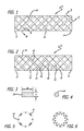
Figure 1 is a cross-sectional elevational schematic diagram of a first embodiment of a braided flow diverting stent according to the invention. -
Fig. 2 is a cross-sectional elevational schematic diagram of a second embodiment of a braided flow diverting stent according to the invention. -
Fig. 3 is a cross-sectional view taken along line 3-3 ofFig. 1 . -
Fig. 4 is a cross-sectional view taken along line 4-4 ofFig. 1 . -
Fig. 5 is a cross-sectional view taken along line 5-5 ofFig. 1 . -
Fig. 6 is a cross-sectional view similar toFig. 5 of an exemplary braided flow diverting stent constructed substantially only from round wires for purposes of comparison. - Referring to the drawings, which are provided by way of example, and not by way of limitation, in a first embodiment, illustrated in
Fig. 1 , the present invention provides for a generally tubular braidedflow diverting stent 10 for treatment of aneurysms, having aproximal end 12, adistal end 14, and an inner lumen (not shown). The generally tubular braided flow diverting stent is preferably formed from a plurality of elongate members, is typically formed from two or more metal wires, or polymeric fibers or strands of material, for example. In a presently preferred aspect, the tubular braided stent optionally may be a self-expanding stent, formed to have a compressed configuration and an expanded configuration. In another presently preferred aspect, the tubular braided stent optionally may be formed of a shape memory material such as a nickel-titanium alloy, for example, having a shape memory position in the expanded configuration. For example, the tubular braided stent may be appropriately heat treated so that the tubular braided stent forms in the desired shape of the expanded shape memory position. - The generally tubular braided flow diverting stent includes one or more first
elongate members 18 helically wound in a first helical direction in a generally tubular shape, and one or more secondelongate members 20, helically wound in a second helical direction counter to the first helical direction and braided with the one or more first elongate members in the generally tubular shape. - Referring to
Fig. 4 , the one or more first elongate members preferably have a substantially round cross-sectional shape, such as a substantially circular cross-sectional shape, for example, although the one or more first elongate members may optionally have a substantially oval cross-sectional shape. The one or more first elongate members preferably also are formed of a plurality of first elongate members, such as a plurality of first wires, for example. As is illustrated inFig. 1 , the generally tubular braided flow diverting stent can be formed with round wires wound helically in a right handed helical direction, and rectangular wires wound helically in a left handed helical direction. - Referring to
Fig. 3 , the one or more second elongate members preferably have a substantially flat radially outer surface. In another presently preferred aspect, the one or more second elongate members typically have a cross-sectional height or thickness H in a first direction and a cross-sectional width or thickness W in a second direction perpendicular to the first direction substantially greater than the cross-sectional height or thickness in the first direction, and typically have a generally rectangular or flattened aspect, for example. The one or more second elongate members preferably also are formed of a plurality of second elongate members, such as a plurality of second wires, for example. The one or more first elongate members and the one or more second elongate members are preferably formed of a material such as stainless steel, nickel-titanium alloy, tantalum, cobalt-chromium alloy, platinum, or the like, or of a polymer, such as a shape memory polymer, or a bioabsorbable material such as poly(D,L-lactic acid-co-glycolic acid) (PGLA), polycaprolactone (PCL), or the like, or combinations thereof. In a presently preferred aspect, some or all of the elongated members used are composed of a bioabsorbable material. In another presently preferred aspect, some or all of the elongate members optionally may be made of a radio-opaque material to facilitate guidance under imaging methods like fluoroscopy. - Referring to
Figs. 5 and 6 , the total wall thickness of a generally tubular braided flow diverting stent according to the invention formed utilizing one or more first elongate members having a substantially round cross-sectional shape, and one or more second elongate members having a substantially flat radially outer surface, illustrated inFig. 5 , is reduced compared to a buildup of thickness of the wall of a generally tubular braided flow diverting stent, having a similar vessel wall coverage and formed of all round wires, illustrated inFig. 6 . - In the method of making the generally tubular braided flow diverting stent of the first embodiment, a braider machine can be loaded with bobbins of round wire in all right handed helical locations, and rectangular wire in all left handed helical locations. Conversely, a braider machine can be loaded with bobbins of round wire in all left handed helical locations, and rectangular wire in all right handed helical locations, for example.
- In a second embodiment, illustrated in
Fig. 2 , in which like elements are indicated by like reference numbers, the present invention provides for a generally tubular braidedflow diverting stent 30 for treatment of aneurysms. The tubular braided flow diverting stent has aproximal end 32, adistal end 34, and an inner lumen (not shown), and is preferably formed from a plurality of elongate members, typically formed from two or more metal wires, or polymeric fibers or strands of material, for example. In one presently preferred aspect, the tubular braided stent optionally may be a self-expanding stent, formed to have a compressed configuration and an expanded configuration. The tubular braided flow diverting stent can be formed of a shape memory material such as a nickel-titanium alloy, for example, having a shape memory position in the expanded configuration. For example, the tubular braided flow diverting stent may be appropriately heat treated so that the tubular braided flow diverting stent forms in the desired shape of the expanded shape memory position. - The generally tubular braided flow diverting stent of the second embodiment preferably includes a plurality of first
elongate members 38 helically wound in a first helical direction in a generally tubular shape, a plurality of secondelongate members 40 helically wound in the first helical direction in the generally tubular shape alternatingly between the plurality of first elongate members, a plurality of thirdelongate members 42 helically wound in a second helical direction counter to the first helical direction and braided with the plurality of first elongate members and the plurality of second elongate members in the generally tubular shape, and a plurality of fourthelongate members 44 helically wound in a second helical direction counter to the first helical direction and braided with the plurality of first elongate members and the plurality of second elongate members in the generally tubular shape alternatingly between the plurality of third elongate members. For example, as is illustrated inFig. 2 , the generally tubular braided flow diverting stent can be formed with alternating round wires and rectangular wires wound helically in both right handed and left handed helical directions. - Referring to
Fig. 4 , the plurality of first elongate members preferably have a substantially round cross-sectional shape, such as a substantially circular cross-sectional shape, for example, although the one or more first elongate members may optionally have a substantially oval cross-sectional shape, and can be formed by a plurality of first wires, for example. - Referring to
Fig. 3 , the plurality of second elongate members preferably have a substantially flat radially outer surface. In another presently preferred aspect, the one or more second elongate members typically have a cross-sectional height or thickness H in a first direction and a cross-sectional width or thickness W in a second direction perpendicular to the first direction substantially greater than the cross-sectional height or thickness in the first direction, and typically have a generally rectangular or flattened aspect, and can be formed by a plurality of wires, for example. - Referring to
Fig. 4 , the plurality of third elongate members preferably have a substantially round cross-sectional shape, such as a substantially circular cross-sectional shape, for example, although the one or more first elongate members may optionally have a substantially oval cross-sectional shape, and can be formed by a plurality of wires, for example. - Referring to
Fig. 3 , the plurality of fourth elongate members preferably have a substantially flat radially outer surface. In another presently preferred aspect, the one or more fourth elongate members typically have a cross-sectional height or thickness H in a first direction and a cross-sectional width or thickness W in a second direction perpendicular to the first direction substantially greater than the cross-sectional height or thickness in the first direction, and typically have a generally rectangular or flattened aspect, and can be formed by a plurality of wires, for example. - The pluralities of first, second, third and fourth elongate members are preferably formed of a material selected from the group consisting of stainless steel, nickel-titanium alloy, tantalum, cobalt-chromium alloy, platinum, and the like, or of a polymer, such as a shape memory polymer, or a bioabsorbable material such as poly(D,L-lactic acid-co-glycolic acid) (PGLA), polycaprolactone (PCL), or the like, and combinations thereof. In a presently preferred aspect, some or all of the elongated members used are composed of a bioabsorbable material. In another presently preferred aspect, some or all of the elongate members optionally may be made of a radio-opaque material to facilitate guidance under imaging methods like fluoroscopy.
- In the method of making the generally tubular braided flow diverting stent of the second embodiment, a braider machine can be loaded with alternating bobbins of round and rectangular wire in both the right handed and left handed helical locations.
- It will be apparent from the foregoing that while particular forms of the invention have been illustrated and described, various modifications can be made without departing from the spirit and scope of the invention. Accordingly, it is not intended that the invention be limited, except as by the appended claims.
Claims (18)
- A generally tubular braided flow diverting stent for treatment of aneurysms, comprising:at least one first elongate member helically wound in a first helical direction in a generally tubular shape, said at least one first elongate member having a substantially round cross-sectional shape; andat least one second elongate member helically wound in a second helical direction counter to said first helical direction and braided with said at least one first elongate member in said generally tubular shape, said at least one second elongate member having a substantially flat radially outer surface.
- The generally tubular braided flow diverting stent of Claim 1, wherein said at least one first elongate member has a substantially circular cross-sectional shape.
- The generally tubular braided flow diverting stent of Claim 1, wherein said at least one first elongate member comprises a plurality of first elongate members, or a plurality of first wires.
- The generally tubular braided flow diverting stent of Claim 1, wherein said at least one second elongate member has a cross-sectional thickness in a first direction and a cross-sectional thickness in a second direction perpendicular to said first direction substantially greater than said cross-sectional thickness in said first direction.
- The generally tubular braided flow diverting stent of Claim 1, wherein said at least one second elongate member has a rectangular cross-sectional shape.
- The generally tubular braided flow diverting stent of Claim 1, wherein said at least one second elongate member comprises a plurality of second elongate members, or a plurality of second wires.
- The generally tubular braided flow diverting stent of Claim 1, wherein said at least one first elongate member and/or said at least one second elongate member is formed of a material selected from the group consisting of stainless steel, nickel-titanium alloy, tantalum, cobalt-chromium alloy, platinum, and combinations thereof.
- The generally tubular braided flow diverting stent of Claim 1, wherein said at least one first elongate member and/or said at least one second elongate member is formed of a bioabsorbable material selected from the group consisting ofpoly(D,L-lactic acid-co-glycolic acid), polycaprolactone, magnesium, and combinations thereof.
- The generally tubular braided flow diverting stent of Claim 3, wherein at least a portion of said plurality of first elongate members comprises a bioabsorbable material.
- The generally tubular braided flow diverting stent of Claim 6 when the at least one second elongate member comprises a plurality of second elongate members, wherein at least a portion of said plurality of second elongate members comprises a bioabsorbable material.
- The generally tubular braided flow diverting stent of Claim 1, wherein said at least one first elongate member and/or said at least one second elongate member is formed of a radio-opaque material.
- A generally tubular braided flow diverting stent for treatment of aneurysms, comprising:a plurality of first elongate members helically wound in a first helical direction in a generally tubular shape, said plurality of first elongate members having a substantially round cross-sectional shape;a plurality of second elongate members helically wound in said first helical direction in said generally tubular shape alternatingly between said plurality of first elongate members, respectively, said plurality of second elongate members having a substantially flat radially outer surface;a plurality of third elongate members helically wound in a second helical direction counter to said first helical direction and braided with said plurality of first elongate members and said plurality of second elongate members in said generally tubular shape, said plurality of third elongate members having a substantially round cross-sectional shape; anda plurality of fourth elongate members helically wound in a second helical direction counter to said first helical direction and braided with said plurality of first elongate members and said plurality of second elongate members in said generally tubular shape alternatingly between said plurality of third elongate members, said plurality of fourth elongate members having a substantially flat radially outer surface.
- The generally tubular braided flow diverting stent of Claim 12, wherein said plurality of first elongate members and said plurality of third elongate members each have a substantially circular cross-sectional shape.
- The generally tubular braided flow diverting stent of Claim 12, wherein said plurality of second elongate members and said plurality of fourth elongate members each have a cross-sectional thickness in a first direction and a cross-sectional thickness in a second direction perpendicular to said first direction substantially greater than said cross-sectional thickness in said first direction.
- The generally tubular braided flow diverting stent of Claim 13, wherein said plurality of second elongate members and said plurality of fourth elongate members each have a rectangular cross-sectional shape.
- The generally tubular braided flow diverting stent of Claim 12, wherein said pluralities of first, second, third and fourth elongate members are formed of a material selected from the group consisting of stainless steel, nickel-titanium alloy, tantalum, cobalt-chromium alloy, platinum, and combinations thereof.
- The generally tubular braided flow diverting stent of Claim 12, wherein at least a portion of said pluralities of first, second, third and fourth elongate members are formed of a bioabsorbable material selected from the group consisting ofpoly(D,L-lactic acid-co-glycolic acid), polycaprolactone, magnesium, and combinations thereof.
- The generally tubular braided flow diverting stent of Claim 12, wherein at least a portion of said pluralities of first, second, third and fourth elongate members are formed of a radio-opaque material.
Applications Claiming Priority (1)
| Application Number | Priority Date | Filing Date | Title |
|---|---|---|---|
| US13/802,225 US20140277386A1 (en) | 2013-03-13 | 2013-03-13 | Braided flow diverter using flat-round technology |
Publications (2)
| Publication Number | Publication Date |
|---|---|
| EP2777641A1 true EP2777641A1 (en) | 2014-09-17 |
| EP2777641B1 EP2777641B1 (en) | 2017-08-02 |
Family
ID=50280156
Family Applications (1)
| Application Number | Title | Priority Date | Filing Date |
|---|---|---|---|
| EP14159051.3A Active EP2777641B1 (en) | 2013-03-13 | 2014-03-12 | Braided flow diverter using flat-round technology |
Country Status (10)
| Country | Link |
|---|---|
| US (2) | US20140277386A1 (en) |
| EP (1) | EP2777641B1 (en) |
| JP (1) | JP6444602B2 (en) |
| KR (1) | KR102213982B1 (en) |
| CN (1) | CN104042297B (en) |
| AU (2) | AU2014201192A1 (en) |
| BR (1) | BR102014005968A2 (en) |
| CA (1) | CA2843912C (en) |
| DK (1) | DK2777641T3 (en) |
| IN (1) | IN2014DE00463A (en) |
Families Citing this family (6)
| Publication number | Priority date | Publication date | Assignee | Title |
|---|---|---|---|---|
| CN105982712B (en) * | 2015-01-28 | 2018-01-30 | 上海交通大学 | Blood flow guider and its implementation |
| CN109833066B (en) * | 2017-11-24 | 2021-02-23 | 先健科技(深圳)有限公司 | occluder |
| WO2019173912A1 (en) * | 2018-03-12 | 2019-09-19 | Fluid Biotech Inc. | Bioabsorbable flow diverting scaffold |
| CN114515375A (en) * | 2022-03-23 | 2022-05-20 | 环心医疗科技(苏州)有限公司 | Medical catheter with composite property |
| EP4311527A1 (en) * | 2022-07-29 | 2024-01-31 | Intressa Vascular S.A. | Implantable 3d braided endovascular prosthesis for remodeling of dissected aorta |
| CN115844605B (en) * | 2023-02-17 | 2023-05-16 | 太原理工大学 | Arterial vessel stent |
Citations (4)
| Publication number | Priority date | Publication date | Assignee | Title |
|---|---|---|---|---|
| US20020179166A1 (en) * | 2001-06-05 | 2002-12-05 | Houston John Graeme | Flow means |
| US20050165470A1 (en) * | 2004-01-22 | 2005-07-28 | Jan Weber | Medical devices |
| WO2010120926A1 (en) * | 2004-05-25 | 2010-10-21 | Chestnut Medical Technologies, Inc. | Vascular stenting for aneurysms |
| EP2510907A1 (en) * | 2011-04-14 | 2012-10-17 | Asahi Intecc Co., Ltd. | Stent |
Family Cites Families (11)
| Publication number | Priority date | Publication date | Assignee | Title |
|---|---|---|---|---|
| SE453258B (en) * | 1986-04-21 | 1988-01-25 | Medinvent Sa | ELASTIC, SELF-EXPANDING PROTEST AND PROCEDURE FOR ITS MANUFACTURING |
| US5019057A (en) * | 1989-10-23 | 1991-05-28 | Cordis Corporation | Catheter having reinforcing strands |
| US5951599A (en) * | 1997-07-09 | 1999-09-14 | Scimed Life Systems, Inc. | Occlusion system for endovascular treatment of an aneurysm |
| US6626939B1 (en) * | 1997-12-18 | 2003-09-30 | Boston Scientific Scimed, Inc. | Stent-graft with bioabsorbable structural support |
| US6063111A (en) | 1998-03-31 | 2000-05-16 | Cordis Corporation | Stent aneurysm treatment system and method |
| US8628564B2 (en) * | 2004-05-25 | 2014-01-14 | Covidien Lp | Methods and apparatus for luminal stenting |
| US7628807B2 (en) * | 2004-11-04 | 2009-12-08 | Boston Scientific Scimed, Inc. | Stent for delivering a therapeutic agent having increased body tissue contact surface |
| DE102007012964A1 (en) * | 2007-03-06 | 2008-09-11 | Phenox Gmbh | Implant for influencing blood flow |
| US20110009941A1 (en) * | 2009-07-08 | 2011-01-13 | Concentric Medical, Inc. | Vascular and bodily duct treatment devices and methods |
| US20110054589A1 (en) | 2009-08-27 | 2011-03-03 | Boston Scientific Scimed, Inc. | Stent with variable cross section braiding filament and method for making same |
| WO2012078955A1 (en) * | 2010-12-10 | 2012-06-14 | Micropen Technologies Corporation | Stents and methods of making stents |
-
2013
- 2013-03-13 US US13/802,225 patent/US20140277386A1/en not_active Abandoned
-
2014
- 2014-02-18 IN IN463DE2014 patent/IN2014DE00463A/en unknown
- 2014-02-26 CA CA2843912A patent/CA2843912C/en not_active Expired - Fee Related
- 2014-03-05 AU AU2014201192A patent/AU2014201192A1/en not_active Abandoned
- 2014-03-06 KR KR1020140026442A patent/KR102213982B1/en not_active Expired - Fee Related
- 2014-03-12 DK DK14159051.3T patent/DK2777641T3/en active
- 2014-03-12 EP EP14159051.3A patent/EP2777641B1/en active Active
- 2014-03-12 JP JP2014048626A patent/JP6444602B2/en active Active
- 2014-03-13 BR BR102014005968A patent/BR102014005968A2/en not_active Application Discontinuation
- 2014-03-13 CN CN201410091592.2A patent/CN104042297B/en active Active
-
2015
- 2015-06-29 US US14/754,125 patent/US11389311B2/en active Active
-
2018
- 2018-09-03 AU AU2018226374A patent/AU2018226374B2/en not_active Expired - Fee Related
Patent Citations (4)
| Publication number | Priority date | Publication date | Assignee | Title |
|---|---|---|---|---|
| US20020179166A1 (en) * | 2001-06-05 | 2002-12-05 | Houston John Graeme | Flow means |
| US20050165470A1 (en) * | 2004-01-22 | 2005-07-28 | Jan Weber | Medical devices |
| WO2010120926A1 (en) * | 2004-05-25 | 2010-10-21 | Chestnut Medical Technologies, Inc. | Vascular stenting for aneurysms |
| EP2510907A1 (en) * | 2011-04-14 | 2012-10-17 | Asahi Intecc Co., Ltd. | Stent |
Also Published As
| Publication number | Publication date |
|---|---|
| US11389311B2 (en) | 2022-07-19 |
| JP6444602B2 (en) | 2018-12-26 |
| KR102213982B1 (en) | 2021-02-09 |
| JP2014176656A (en) | 2014-09-25 |
| DK2777641T3 (en) | 2017-10-02 |
| CN104042297A (en) | 2014-09-17 |
| AU2018226374A1 (en) | 2018-09-27 |
| CA2843912A1 (en) | 2014-09-13 |
| US20150297374A1 (en) | 2015-10-22 |
| AU2014201192A1 (en) | 2014-10-02 |
| CN104042297B (en) | 2020-01-10 |
| US20140277386A1 (en) | 2014-09-18 |
| CA2843912C (en) | 2021-05-25 |
| IN2014DE00463A (en) | 2015-06-12 |
| BR102014005968A2 (en) | 2015-10-06 |
| EP2777641B1 (en) | 2017-08-02 |
| AU2018226374B2 (en) | 2020-01-23 |
| KR20140112403A (en) | 2014-09-23 |
Similar Documents
| Publication | Publication Date | Title |
|---|---|---|
| AU2018226374B2 (en) | Braided flow diverter using flat-round technology | |
| US11819217B2 (en) | Embolic devices and methods of manufacturing same | |
| US11376012B2 (en) | Devices, systems, and methods for treatment of vascular defects | |
| US20210137710A1 (en) | Method of making a multi-strand implant with enhanced radiopacity | |
| US20230329888A1 (en) | Stent Delivery System And Method | |
| AU2018253740B2 (en) | Braid expansion ring with markers | |
| EP4194020B1 (en) | Implantable medical device | |
| US20260090806A1 (en) | Vaso-occlusive devices | |
| CN113995551A (en) | Blood flow guide support and system | |
| JP6425981B2 (en) | Self-expanding stent | |
| JP2016013285A (en) | Medical tube body |
Legal Events
| Date | Code | Title | Description |
|---|---|---|---|
| 17P | Request for examination filed |
Effective date: 20140312 |
|
| AK | Designated contracting states |
Kind code of ref document: A1 Designated state(s): AL AT BE BG CH CY CZ DE DK EE ES FI FR GB GR HR HU IE IS IT LI LT LU LV MC MK MT NL NO PL PT RO RS SE SI SK SM TR |
|
| AX | Request for extension of the european patent |
Extension state: BA ME |
|
| PUAI | Public reference made under article 153(3) epc to a published international application that has entered the european phase |
Free format text: ORIGINAL CODE: 0009012 |
|
| R17P | Request for examination filed (corrected) |
Effective date: 20140910 |
|
| RBV | Designated contracting states (corrected) |
Designated state(s): AL AT BE BG CH CY CZ DE DK EE ES FI FR GB GR HR HU IE IS IT LI LT LU LV MC MK MT NL NO PL PT RO RS SE SI SK SM TR |
|
| 17Q | First examination report despatched |
Effective date: 20151207 |
|
| GRAP | Despatch of communication of intention to grant a patent |
Free format text: ORIGINAL CODE: EPIDOSNIGR1 |
|
| INTG | Intention to grant announced |
Effective date: 20170208 |
|
| RIN1 | Information on inventor provided before grant (corrected) |
Inventor name: LORENZO, JUAN A. Inventor name: SLAZAS, ROBERT |
|
| GRAS | Grant fee paid |
Free format text: ORIGINAL CODE: EPIDOSNIGR3 |
|
| GRAA | (expected) grant |
Free format text: ORIGINAL CODE: 0009210 |
|
| AK | Designated contracting states |
Kind code of ref document: B1 Designated state(s): AL AT BE BG CH CY CZ DE DK EE ES FI FR GB GR HR HU IE IS IT LI LT LU LV MC MK MT NL NO PL PT RO RS SE SI SK SM TR |
|
| REG | Reference to a national code |
Ref country code: CH Ref legal event code: EP Ref country code: CH Ref legal event code: NV Representative=s name: E. BLUM AND CO. AG PATENT- UND MARKENANWAELTE , CH Ref country code: AT Ref legal event code: REF Ref document number: 913638 Country of ref document: AT Kind code of ref document: T Effective date: 20170815 |
|
| REG | Reference to a national code |
Ref country code: IE Ref legal event code: FG4D |
|
| REG | Reference to a national code |
Ref country code: DE Ref legal event code: R096 Ref document number: 602014012407 Country of ref document: DE |
|
| REG | Reference to a national code |
Ref country code: DK Ref legal event code: T3 Effective date: 20170928 |
|
| REG | Reference to a national code |
Ref country code: NL Ref legal event code: MP Effective date: 20170802 |
|
| REG | Reference to a national code |
Ref country code: AT Ref legal event code: MK05 Ref document number: 913638 Country of ref document: AT Kind code of ref document: T Effective date: 20170802 |
|
| REG | Reference to a national code |
Ref country code: LT Ref legal event code: MG4D |
|
| PG25 | Lapsed in a contracting state [announced via postgrant information from national office to epo] |
Ref country code: LT Free format text: LAPSE BECAUSE OF FAILURE TO SUBMIT A TRANSLATION OF THE DESCRIPTION OR TO PAY THE FEE WITHIN THE PRESCRIBED TIME-LIMIT Effective date: 20170802 Ref country code: SE Free format text: LAPSE BECAUSE OF FAILURE TO SUBMIT A TRANSLATION OF THE DESCRIPTION OR TO PAY THE FEE WITHIN THE PRESCRIBED TIME-LIMIT Effective date: 20170802 Ref country code: NL Free format text: LAPSE BECAUSE OF FAILURE TO SUBMIT A TRANSLATION OF THE DESCRIPTION OR TO PAY THE FEE WITHIN THE PRESCRIBED TIME-LIMIT Effective date: 20170802 Ref country code: NO Free format text: LAPSE BECAUSE OF FAILURE TO SUBMIT A TRANSLATION OF THE DESCRIPTION OR TO PAY THE FEE WITHIN THE PRESCRIBED TIME-LIMIT Effective date: 20171102 Ref country code: FI Free format text: LAPSE BECAUSE OF FAILURE TO SUBMIT A TRANSLATION OF THE DESCRIPTION OR TO PAY THE FEE WITHIN THE PRESCRIBED TIME-LIMIT Effective date: 20170802 Ref country code: HR Free format text: LAPSE BECAUSE OF FAILURE TO SUBMIT A TRANSLATION OF THE DESCRIPTION OR TO PAY THE FEE WITHIN THE PRESCRIBED TIME-LIMIT Effective date: 20170802 Ref country code: AT Free format text: LAPSE BECAUSE OF FAILURE TO SUBMIT A TRANSLATION OF THE DESCRIPTION OR TO PAY THE FEE WITHIN THE PRESCRIBED TIME-LIMIT Effective date: 20170802 |
|
| REG | Reference to a national code |
Ref country code: FR Ref legal event code: PLFP Year of fee payment: 5 |
|
| PG25 | Lapsed in a contracting state [announced via postgrant information from national office to epo] |
Ref country code: IS Free format text: LAPSE BECAUSE OF FAILURE TO SUBMIT A TRANSLATION OF THE DESCRIPTION OR TO PAY THE FEE WITHIN THE PRESCRIBED TIME-LIMIT Effective date: 20171202 Ref country code: PL Free format text: LAPSE BECAUSE OF FAILURE TO SUBMIT A TRANSLATION OF THE DESCRIPTION OR TO PAY THE FEE WITHIN THE PRESCRIBED TIME-LIMIT Effective date: 20170802 Ref country code: ES Free format text: LAPSE BECAUSE OF FAILURE TO SUBMIT A TRANSLATION OF THE DESCRIPTION OR TO PAY THE FEE WITHIN THE PRESCRIBED TIME-LIMIT Effective date: 20170802 Ref country code: RS Free format text: LAPSE BECAUSE OF FAILURE TO SUBMIT A TRANSLATION OF THE DESCRIPTION OR TO PAY THE FEE WITHIN THE PRESCRIBED TIME-LIMIT Effective date: 20170802 Ref country code: BG Free format text: LAPSE BECAUSE OF FAILURE TO SUBMIT A TRANSLATION OF THE DESCRIPTION OR TO PAY THE FEE WITHIN THE PRESCRIBED TIME-LIMIT Effective date: 20171102 Ref country code: LV Free format text: LAPSE BECAUSE OF FAILURE TO SUBMIT A TRANSLATION OF THE DESCRIPTION OR TO PAY THE FEE WITHIN THE PRESCRIBED TIME-LIMIT Effective date: 20170802 Ref country code: GR Free format text: LAPSE BECAUSE OF FAILURE TO SUBMIT A TRANSLATION OF THE DESCRIPTION OR TO PAY THE FEE WITHIN THE PRESCRIBED TIME-LIMIT Effective date: 20171103 |
|
| PG25 | Lapsed in a contracting state [announced via postgrant information from national office to epo] |
Ref country code: CZ Free format text: LAPSE BECAUSE OF FAILURE TO SUBMIT A TRANSLATION OF THE DESCRIPTION OR TO PAY THE FEE WITHIN THE PRESCRIBED TIME-LIMIT Effective date: 20170802 Ref country code: RO Free format text: LAPSE BECAUSE OF FAILURE TO SUBMIT A TRANSLATION OF THE DESCRIPTION OR TO PAY THE FEE WITHIN THE PRESCRIBED TIME-LIMIT Effective date: 20170802 |
|
| REG | Reference to a national code |
Ref country code: DE Ref legal event code: R097 Ref document number: 602014012407 Country of ref document: DE |
|
| PG25 | Lapsed in a contracting state [announced via postgrant information from national office to epo] |
Ref country code: SK Free format text: LAPSE BECAUSE OF FAILURE TO SUBMIT A TRANSLATION OF THE DESCRIPTION OR TO PAY THE FEE WITHIN THE PRESCRIBED TIME-LIMIT Effective date: 20170802 Ref country code: EE Free format text: LAPSE BECAUSE OF FAILURE TO SUBMIT A TRANSLATION OF THE DESCRIPTION OR TO PAY THE FEE WITHIN THE PRESCRIBED TIME-LIMIT Effective date: 20170802 Ref country code: SM Free format text: LAPSE BECAUSE OF FAILURE TO SUBMIT A TRANSLATION OF THE DESCRIPTION OR TO PAY THE FEE WITHIN THE PRESCRIBED TIME-LIMIT Effective date: 20170802 |
|
| PLBE | No opposition filed within time limit |
Free format text: ORIGINAL CODE: 0009261 |
|
| STAA | Information on the status of an ep patent application or granted ep patent |
Free format text: STATUS: NO OPPOSITION FILED WITHIN TIME LIMIT |
|
| 26N | No opposition filed |
Effective date: 20180503 |
|
| PG25 | Lapsed in a contracting state [announced via postgrant information from national office to epo] |
Ref country code: SI Free format text: LAPSE BECAUSE OF FAILURE TO SUBMIT A TRANSLATION OF THE DESCRIPTION OR TO PAY THE FEE WITHIN THE PRESCRIBED TIME-LIMIT Effective date: 20170802 |
|
| PG25 | Lapsed in a contracting state [announced via postgrant information from national office to epo] |
Ref country code: MC Free format text: LAPSE BECAUSE OF FAILURE TO SUBMIT A TRANSLATION OF THE DESCRIPTION OR TO PAY THE FEE WITHIN THE PRESCRIBED TIME-LIMIT Effective date: 20170802 |
|
| REG | Reference to a national code |
Ref country code: BE Ref legal event code: MM Effective date: 20180331 |
|
| REG | Reference to a national code |
Ref country code: IE Ref legal event code: MM4A |
|
| PG25 | Lapsed in a contracting state [announced via postgrant information from national office to epo] |
Ref country code: LU Free format text: LAPSE BECAUSE OF NON-PAYMENT OF DUE FEES Effective date: 20180312 |
|
| PG25 | Lapsed in a contracting state [announced via postgrant information from national office to epo] |
Ref country code: IE Free format text: LAPSE BECAUSE OF NON-PAYMENT OF DUE FEES Effective date: 20180312 |
|
| PG25 | Lapsed in a contracting state [announced via postgrant information from national office to epo] |
Ref country code: IT Free format text: LAPSE BECAUSE OF NON-PAYMENT OF DUE FEES Effective date: 20180312 Ref country code: BE Free format text: LAPSE BECAUSE OF NON-PAYMENT OF DUE FEES Effective date: 20180331 |
|
| PG25 | Lapsed in a contracting state [announced via postgrant information from national office to epo] |
Ref country code: MT Free format text: LAPSE BECAUSE OF NON-PAYMENT OF DUE FEES Effective date: 20180312 |
|
| PG25 | Lapsed in a contracting state [announced via postgrant information from national office to epo] |
Ref country code: TR Free format text: LAPSE BECAUSE OF FAILURE TO SUBMIT A TRANSLATION OF THE DESCRIPTION OR TO PAY THE FEE WITHIN THE PRESCRIBED TIME-LIMIT Effective date: 20170802 |
|
| PGFP | Annual fee paid to national office [announced via postgrant information from national office to epo] |
Ref country code: DK Payment date: 20200310 Year of fee payment: 7 |
|
| PG25 | Lapsed in a contracting state [announced via postgrant information from national office to epo] |
Ref country code: HU Free format text: LAPSE BECAUSE OF FAILURE TO SUBMIT A TRANSLATION OF THE DESCRIPTION OR TO PAY THE FEE WITHIN THE PRESCRIBED TIME-LIMIT; INVALID AB INITIO Effective date: 20140312 Ref country code: PT Free format text: LAPSE BECAUSE OF FAILURE TO SUBMIT A TRANSLATION OF THE DESCRIPTION OR TO PAY THE FEE WITHIN THE PRESCRIBED TIME-LIMIT Effective date: 20170802 |
|
| PGFP | Annual fee paid to national office [announced via postgrant information from national office to epo] |
Ref country code: CH Payment date: 20200313 Year of fee payment: 7 |
|
| PG25 | Lapsed in a contracting state [announced via postgrant information from national office to epo] |
Ref country code: CY Free format text: LAPSE BECAUSE OF FAILURE TO SUBMIT A TRANSLATION OF THE DESCRIPTION OR TO PAY THE FEE WITHIN THE PRESCRIBED TIME-LIMIT Effective date: 20170802 Ref country code: MK Free format text: LAPSE BECAUSE OF NON-PAYMENT OF DUE FEES Effective date: 20170802 |
|
| PG25 | Lapsed in a contracting state [announced via postgrant information from national office to epo] |
Ref country code: AL Free format text: LAPSE BECAUSE OF FAILURE TO SUBMIT A TRANSLATION OF THE DESCRIPTION OR TO PAY THE FEE WITHIN THE PRESCRIBED TIME-LIMIT Effective date: 20170802 |
|
| REG | Reference to a national code |
Ref country code: CH Ref legal event code: PL |
|
| REG | Reference to a national code |
Ref country code: DK Ref legal event code: EBP Effective date: 20210331 |
|
| PG25 | Lapsed in a contracting state [announced via postgrant information from national office to epo] |
Ref country code: CH Free format text: LAPSE BECAUSE OF NON-PAYMENT OF DUE FEES Effective date: 20210331 Ref country code: LI Free format text: LAPSE BECAUSE OF NON-PAYMENT OF DUE FEES Effective date: 20210331 |
|
| PG25 | Lapsed in a contracting state [announced via postgrant information from national office to epo] |
Ref country code: DK Free format text: LAPSE BECAUSE OF NON-PAYMENT OF DUE FEES Effective date: 20210331 |
|
| PGFP | Annual fee paid to national office [announced via postgrant information from national office to epo] |
Ref country code: GB Payment date: 20220203 Year of fee payment: 9 |
|
| PGFP | Annual fee paid to national office [announced via postgrant information from national office to epo] |
Ref country code: FR Payment date: 20230208 Year of fee payment: 10 |
|
| GBPC | Gb: european patent ceased through non-payment of renewal fee |
Effective date: 20230312 |
|
| PG25 | Lapsed in a contracting state [announced via postgrant information from national office to epo] |
Ref country code: GB Free format text: LAPSE BECAUSE OF NON-PAYMENT OF DUE FEES Effective date: 20230312 |
|
| PG25 | Lapsed in a contracting state [announced via postgrant information from national office to epo] |
Ref country code: GB Free format text: LAPSE BECAUSE OF NON-PAYMENT OF DUE FEES Effective date: 20230312 |
|
| PG25 | Lapsed in a contracting state [announced via postgrant information from national office to epo] |
Ref country code: FR Free format text: LAPSE BECAUSE OF NON-PAYMENT OF DUE FEES Effective date: 20240331 |
|
| PG25 | Lapsed in a contracting state [announced via postgrant information from national office to epo] |
Ref country code: FR Free format text: LAPSE BECAUSE OF NON-PAYMENT OF DUE FEES Effective date: 20240331 |
|
| PGFP | Annual fee paid to national office [announced via postgrant information from national office to epo] |
Ref country code: DE Payment date: 20260204 Year of fee payment: 13 |