EP2777626B1 - System for implanting a secondary glenoid prosthesis - Google Patents
System for implanting a secondary glenoid prosthesis Download PDFInfo
- Publication number
- EP2777626B1 EP2777626B1 EP14157143.0A EP14157143A EP2777626B1 EP 2777626 B1 EP2777626 B1 EP 2777626B1 EP 14157143 A EP14157143 A EP 14157143A EP 2777626 B1 EP2777626 B1 EP 2777626B1
- Authority
- EP
- European Patent Office
- Prior art keywords
- component
- glenoid
- scapula
- glenoid component
- patient
- Prior art date
- Legal status (The legal status is an assumption and is not a legal conclusion. Google has not performed a legal analysis and makes no representation as to the accuracy of the status listed.)
- Active
Links
- 241001653121 Glenoides Species 0.000 title claims description 155
- 210000001991 scapula Anatomy 0.000 claims description 78
- 238000001356 surgical procedure Methods 0.000 claims description 17
- 210000004095 humeral head Anatomy 0.000 claims description 6
- 210000000988 bone and bone Anatomy 0.000 description 45
- 239000011800 void material Substances 0.000 description 33
- 238000000034 method Methods 0.000 description 26
- 239000007943 implant Substances 0.000 description 16
- 238000002513 implantation Methods 0.000 description 11
- 230000003019 stabilising effect Effects 0.000 description 9
- 230000006835 compression Effects 0.000 description 8
- 238000007906 compression Methods 0.000 description 8
- 239000000463 material Substances 0.000 description 7
- 239000004698 Polyethylene Substances 0.000 description 6
- -1 polyethylene Polymers 0.000 description 6
- 229920000573 polyethylene Polymers 0.000 description 6
- 229910052751 metal Inorganic materials 0.000 description 5
- 239000002184 metal Substances 0.000 description 5
- 210000003484 anatomy Anatomy 0.000 description 4
- 210000002758 humerus Anatomy 0.000 description 4
- 229910000531 Co alloy Inorganic materials 0.000 description 3
- 229910001069 Ti alloy Inorganic materials 0.000 description 3
- 229910000883 Ti6Al4V Inorganic materials 0.000 description 3
- RTAQQCXQSZGOHL-UHFFFAOYSA-N Titanium Chemical compound [Ti] RTAQQCXQSZGOHL-UHFFFAOYSA-N 0.000 description 3
- 229920010741 Ultra High Molecular Weight Polyethylene (UHMWPE) Polymers 0.000 description 3
- WAIPAZQMEIHHTJ-UHFFFAOYSA-N [Cr].[Co] Chemical class [Cr].[Co] WAIPAZQMEIHHTJ-UHFFFAOYSA-N 0.000 description 3
- 229910045601 alloy Inorganic materials 0.000 description 3
- 239000000956 alloy Substances 0.000 description 3
- 229910017052 cobalt Inorganic materials 0.000 description 3
- 239000010941 cobalt Substances 0.000 description 3
- GUTLYIVDDKVIGB-UHFFFAOYSA-N cobalt atom Chemical compound [Co] GUTLYIVDDKVIGB-UHFFFAOYSA-N 0.000 description 3
- 229910001220 stainless steel Inorganic materials 0.000 description 3
- 239000010936 titanium Substances 0.000 description 3
- 229910052719 titanium Inorganic materials 0.000 description 3
- 239000002639 bone cement Substances 0.000 description 2
- 229910052588 hydroxylapatite Inorganic materials 0.000 description 2
- 150000002739 metals Chemical class 0.000 description 2
- 230000000149 penetrating effect Effects 0.000 description 2
- XYJRXVWERLGGKC-UHFFFAOYSA-D pentacalcium;hydroxide;triphosphate Chemical compound [OH-].[Ca+2].[Ca+2].[Ca+2].[Ca+2].[Ca+2].[O-]P([O-])([O-])=O.[O-]P([O-])([O-])=O.[O-]P([O-])([O-])=O XYJRXVWERLGGKC-UHFFFAOYSA-D 0.000 description 2
- 229920000642 polymer Polymers 0.000 description 2
- 238000004381 surface treatment Methods 0.000 description 2
- 208000006820 Arthralgia Diseases 0.000 description 1
- 206010065687 Bone loss Diseases 0.000 description 1
- 208000005137 Joint instability Diseases 0.000 description 1
- 238000011882 arthroplasty Methods 0.000 description 1
- 230000000295 complement effect Effects 0.000 description 1
- 210000000852 deltoid muscle Anatomy 0.000 description 1
- 201000010099 disease Diseases 0.000 description 1
- 208000037265 diseases, disorders, signs and symptoms Diseases 0.000 description 1
- 239000012634 fragment Substances 0.000 description 1
- 208000014674 injury Diseases 0.000 description 1
- 238000003780 insertion Methods 0.000 description 1
- 230000037431 insertion Effects 0.000 description 1
- 210000003205 muscle Anatomy 0.000 description 1
- 238000007493 shaping process Methods 0.000 description 1
- 210000004872 soft tissue Anatomy 0.000 description 1
- 230000008733 trauma Effects 0.000 description 1
Images


Classifications
-
- A—HUMAN NECESSITIES
- A61—MEDICAL OR VETERINARY SCIENCE; HYGIENE
- A61F—FILTERS IMPLANTABLE INTO BLOOD VESSELS; PROSTHESES; DEVICES PROVIDING PATENCY TO, OR PREVENTING COLLAPSING OF, TUBULAR STRUCTURES OF THE BODY, e.g. STENTS; ORTHOPAEDIC, NURSING OR CONTRACEPTIVE DEVICES; FOMENTATION; TREATMENT OR PROTECTION OF EYES OR EARS; BANDAGES, DRESSINGS OR ABSORBENT PADS; FIRST-AID KITS
- A61F2/00—Filters implantable into blood vessels; Prostheses, i.e. artificial substitutes or replacements for parts of the body; Appliances for connecting them with the body; Devices providing patency to, or preventing collapsing of, tubular structures of the body, e.g. stents
- A61F2/02—Prostheses implantable into the body
- A61F2/30—Joints
- A61F2/40—Joints for shoulders
- A61F2/4081—Glenoid components, e.g. cups
-
- A—HUMAN NECESSITIES
- A61—MEDICAL OR VETERINARY SCIENCE; HYGIENE
- A61F—FILTERS IMPLANTABLE INTO BLOOD VESSELS; PROSTHESES; DEVICES PROVIDING PATENCY TO, OR PREVENTING COLLAPSING OF, TUBULAR STRUCTURES OF THE BODY, e.g. STENTS; ORTHOPAEDIC, NURSING OR CONTRACEPTIVE DEVICES; FOMENTATION; TREATMENT OR PROTECTION OF EYES OR EARS; BANDAGES, DRESSINGS OR ABSORBENT PADS; FIRST-AID KITS
- A61F2/00—Filters implantable into blood vessels; Prostheses, i.e. artificial substitutes or replacements for parts of the body; Appliances for connecting them with the body; Devices providing patency to, or preventing collapsing of, tubular structures of the body, e.g. stents
- A61F2/02—Prostheses implantable into the body
- A61F2/30—Joints
- A61F2/40—Joints for shoulders
-
- A—HUMAN NECESSITIES
- A61—MEDICAL OR VETERINARY SCIENCE; HYGIENE
- A61F—FILTERS IMPLANTABLE INTO BLOOD VESSELS; PROSTHESES; DEVICES PROVIDING PATENCY TO, OR PREVENTING COLLAPSING OF, TUBULAR STRUCTURES OF THE BODY, e.g. STENTS; ORTHOPAEDIC, NURSING OR CONTRACEPTIVE DEVICES; FOMENTATION; TREATMENT OR PROTECTION OF EYES OR EARS; BANDAGES, DRESSINGS OR ABSORBENT PADS; FIRST-AID KITS
- A61F2/00—Filters implantable into blood vessels; Prostheses, i.e. artificial substitutes or replacements for parts of the body; Appliances for connecting them with the body; Devices providing patency to, or preventing collapsing of, tubular structures of the body, e.g. stents
- A61F2/02—Prostheses implantable into the body
- A61F2/30—Joints
- A61F2/46—Special tools or methods for implanting or extracting artificial joints, accessories, bone grafts or substitutes, or particular adaptations therefor
- A61F2/4603—Special tools or methods for implanting or extracting artificial joints, accessories, bone grafts or substitutes, or particular adaptations therefor for insertion or extraction of endoprosthetic joints or of accessories thereof
- A61F2/4612—Special tools or methods for implanting or extracting artificial joints, accessories, bone grafts or substitutes, or particular adaptations therefor for insertion or extraction of endoprosthetic joints or of accessories thereof of shoulders
-
- A—HUMAN NECESSITIES
- A61—MEDICAL OR VETERINARY SCIENCE; HYGIENE
- A61F—FILTERS IMPLANTABLE INTO BLOOD VESSELS; PROSTHESES; DEVICES PROVIDING PATENCY TO, OR PREVENTING COLLAPSING OF, TUBULAR STRUCTURES OF THE BODY, e.g. STENTS; ORTHOPAEDIC, NURSING OR CONTRACEPTIVE DEVICES; FOMENTATION; TREATMENT OR PROTECTION OF EYES OR EARS; BANDAGES, DRESSINGS OR ABSORBENT PADS; FIRST-AID KITS
- A61F2/00—Filters implantable into blood vessels; Prostheses, i.e. artificial substitutes or replacements for parts of the body; Appliances for connecting them with the body; Devices providing patency to, or preventing collapsing of, tubular structures of the body, e.g. stents
- A61F2/02—Prostheses implantable into the body
- A61F2/30—Joints
- A61F2/30721—Accessories
- A61F2/30749—Fixation appliances for connecting prostheses to the body
-
- A—HUMAN NECESSITIES
- A61—MEDICAL OR VETERINARY SCIENCE; HYGIENE
- A61F—FILTERS IMPLANTABLE INTO BLOOD VESSELS; PROSTHESES; DEVICES PROVIDING PATENCY TO, OR PREVENTING COLLAPSING OF, TUBULAR STRUCTURES OF THE BODY, e.g. STENTS; ORTHOPAEDIC, NURSING OR CONTRACEPTIVE DEVICES; FOMENTATION; TREATMENT OR PROTECTION OF EYES OR EARS; BANDAGES, DRESSINGS OR ABSORBENT PADS; FIRST-AID KITS
- A61F2/00—Filters implantable into blood vessels; Prostheses, i.e. artificial substitutes or replacements for parts of the body; Appliances for connecting them with the body; Devices providing patency to, or preventing collapsing of, tubular structures of the body, e.g. stents
- A61F2/02—Prostheses implantable into the body
- A61F2/30—Joints
- A61F2002/30001—Additional features of subject-matter classified in A61F2/28, A61F2/30 and subgroups thereof
- A61F2002/30316—The prosthesis having different structural features at different locations within the same prosthesis; Connections between prosthetic parts; Special structural features of bone or joint prostheses not otherwise provided for
- A61F2002/30329—Connections or couplings between prosthetic parts, e.g. between modular parts; Connecting elements
- A61F2002/30476—Connections or couplings between prosthetic parts, e.g. between modular parts; Connecting elements locked by an additional locking mechanism
- A61F2002/30484—Mechanically expandable devices located on the first prosthetic part for locking into or onto the second prosthetic part
-
- A—HUMAN NECESSITIES
- A61—MEDICAL OR VETERINARY SCIENCE; HYGIENE
- A61F—FILTERS IMPLANTABLE INTO BLOOD VESSELS; PROSTHESES; DEVICES PROVIDING PATENCY TO, OR PREVENTING COLLAPSING OF, TUBULAR STRUCTURES OF THE BODY, e.g. STENTS; ORTHOPAEDIC, NURSING OR CONTRACEPTIVE DEVICES; FOMENTATION; TREATMENT OR PROTECTION OF EYES OR EARS; BANDAGES, DRESSINGS OR ABSORBENT PADS; FIRST-AID KITS
- A61F2/00—Filters implantable into blood vessels; Prostheses, i.e. artificial substitutes or replacements for parts of the body; Appliances for connecting them with the body; Devices providing patency to, or preventing collapsing of, tubular structures of the body, e.g. stents
- A61F2/02—Prostheses implantable into the body
- A61F2/30—Joints
- A61F2002/30001—Additional features of subject-matter classified in A61F2/28, A61F2/30 and subgroups thereof
- A61F2002/30667—Features concerning an interaction with the environment or a particular use of the prosthesis
- A61F2002/3069—Revision endoprostheses
-
- A—HUMAN NECESSITIES
- A61—MEDICAL OR VETERINARY SCIENCE; HYGIENE
- A61F—FILTERS IMPLANTABLE INTO BLOOD VESSELS; PROSTHESES; DEVICES PROVIDING PATENCY TO, OR PREVENTING COLLAPSING OF, TUBULAR STRUCTURES OF THE BODY, e.g. STENTS; ORTHOPAEDIC, NURSING OR CONTRACEPTIVE DEVICES; FOMENTATION; TREATMENT OR PROTECTION OF EYES OR EARS; BANDAGES, DRESSINGS OR ABSORBENT PADS; FIRST-AID KITS
- A61F2/00—Filters implantable into blood vessels; Prostheses, i.e. artificial substitutes or replacements for parts of the body; Appliances for connecting them with the body; Devices providing patency to, or preventing collapsing of, tubular structures of the body, e.g. stents
- A61F2/02—Prostheses implantable into the body
- A61F2/30—Joints
- A61F2/30721—Accessories
- A61F2/30734—Modular inserts, sleeves or augments, e.g. placed on proximal part of stem for fixation purposes or wedges for bridging a bone defect
- A61F2002/30736—Augments or augmentation pieces, e.g. wedges or blocks for bridging a bone defect
-
- A—HUMAN NECESSITIES
- A61—MEDICAL OR VETERINARY SCIENCE; HYGIENE
- A61F—FILTERS IMPLANTABLE INTO BLOOD VESSELS; PROSTHESES; DEVICES PROVIDING PATENCY TO, OR PREVENTING COLLAPSING OF, TUBULAR STRUCTURES OF THE BODY, e.g. STENTS; ORTHOPAEDIC, NURSING OR CONTRACEPTIVE DEVICES; FOMENTATION; TREATMENT OR PROTECTION OF EYES OR EARS; BANDAGES, DRESSINGS OR ABSORBENT PADS; FIRST-AID KITS
- A61F2/00—Filters implantable into blood vessels; Prostheses, i.e. artificial substitutes or replacements for parts of the body; Appliances for connecting them with the body; Devices providing patency to, or preventing collapsing of, tubular structures of the body, e.g. stents
- A61F2/02—Prostheses implantable into the body
- A61F2/30—Joints
- A61F2/40—Joints for shoulders
- A61F2/4081—Glenoid components, e.g. cups
- A61F2002/4085—Glenoid components, e.g. cups having a convex shape, e.g. hemispherical heads
Definitions
- the present invention relates generally to orthopaedic implants, and more particularly to, a system for implanting a secondary glenoid prosthesis.
- a humeral prosthesis is used to replace the natural head of the patient's humerus.
- the humeral prosthesis typically includes an elongated stem component that is implanted into the intramedullary canal of the patient's humerus and a hemispherically-shaped prosthetic head component that is secured to the stem component.
- the natural glenoid surface of the scapula is resurfaced or otherwise replaced with a glenoid component that provides a bearing surface upon which the prosthetic head component of the humeral prosthesis articulates.
- a reverse shoulder implant reverses the anatomy, or structure, of the healthy shoulder.
- a reverse shoulder implant is designed such that the prosthetic head (i.e. the "ball” in the ball-and-socket joint) known as a glenosphere component is secured to the patient's scapula, with the corresponding concave bearing (i.e.
- the "socket" in the ball-and-socket joint known as a humeral cup being secured to the patient's humerus.
- a humeral cup being secured to the patient's humerus.
- US-A-2012/253467 discloses a shoulder arthroplasty system which includes a baseplate for fastening to a patient's scapula, and first and second glenoid components which can be attached to the baseplate.
- a first glenoid component has a concave surface for articulation with a humeral component.
- a second glenoid component is a glenosphere component which has a convex surface for articulation with a socket component on the patient's humerus.
- the invention provides a system for implanting a shoulder prosthesis in a scapula of a patient, as defined in claim 1.
- the system includes an anatomic bearing and also a glenosphere component, in which each of them individually is suitable for use in the secondary glenoid component.
- the system can be used in a method of implanting a shoulder prosthesis in a scapula of a patient includes the step of placing a guide over a primary glenoid component previously implanted within the scapula of the patient.
- the method can include removing the primary glenoid component from the scapula and preparing the scapula for implantation of a secondary glenoid component, in which the removing and preparing steps occur simultaneously.
- the removing step may include using a tool to penetrate the primary glenoid and into the glenoid surface of the scapula.
- the removing step may further include creating a void in the bone tissue of the scapula that is at least as large as and occupies at least as much space as an anchor extending from the primary glenoid component and which implants the primary glenoid component within the bone tissue of the scapula, thereby eliminating the anchor.
- the removing step may include the step of removing unanchored primary glenoid component from the bone tissue of the scapula.
- the scapula may be prepared for implantation of the secondary glenoid component by creation of the void in the bone surface of the scapula.
- the method may further include the steps of providing a secondary glenoid component comprising an anchor having a geometry that generally conforms to a geometry of the void in the bone tissue of the scapula and implanting the anchor of the secondary glenoid component within the void.
- the method may further include the step of assessing the extent of damage to the shoulder of the patient. If the extent of damage is at a first level, the method may include the step of implanting an anchor of an anatomic secondary glenoid component within the void. Alternatively, if the extent of the damage is at a second level, the method may include the step of implanting an anchor of a reverse secondary glenoid component within the void.
- the method further includes the steps of removing fragments of the primary glenoid component that are no longer anchored to the bone tissue of the scapula after the step of creating a void and implanting a secondary glenoid component within the void.
- the secondary component may include a platform having a lateral surface and an opposite medial surface and adapted to contact the scapula of the patient.
- the platform may further include at least one anchor extending from the medial surface of the platform, in which the anchor is adapted to be implanted within the void.
- the anchor may be in the form of a peg extending outwardly from a central portion of the medial surface of the platform.
- the anchor may be in the form of a keel extending outwardly from the medial surface of the platform.
- the method may further include assessing the extent of damage to the shoulder of the patient during surgery. If the extent of the damage is at a first level, the method may further include implanting an anchor of an anatomic secondary glenoid component within the void. Alternatively, if the extent of the damage is at a second level, the method may further include implanting an anchor of a reverse secondary glenoid component within the void.
- the anchor of anatomic secondary glenoid component and the anchor of the reverse secondary glenoid have geometries that generally conform to a geometry of the void.
- the assessing step allows a surgeon to change plans intra-operatively between anatomic and reverse secondary glenoid components.
- the step of creating the void further includes the steps of placing a guide over a primary glenoid component previously implanted within the scapula of the patient and removing the primary glenoid component from the scapula.
- the step of creating the void still further may include the step of preparing the scapula for implantation of a secondary glenoid component, in which the removing and preparing steps occur simultaneously.
- the scapula is prepared for implantation of the secondary glenoid component by creation of the void in the glenoid surface of the scapula.
- the method further includes the steps of providing the secondary glenoid component comprising an anchor having dimensions that conform to dimensions of the void in the glenoid surface of the scapula and implanting the anchor of the secondary glenoid component within the void.
- the first anchor of the anatomic glenoid component and the second anchor of the reverse secondary glenoid have geometries that conform generally conform to a geometry of the void.
- the method further includes the steps of placing a guide over a primary glenoid component previously implanted within the scapula of the patient and removing the primary glenoid component from the scapula.
- the method further includes the step of preparing the scapula for implantation of a secondary glenoid component, in which the removing and preparing steps occur simultaneously.
- the anatomic glenoid component and the reverse glenoid component may be part of a platform system.
- the platform system may include a platform having an anchor extending therefrom and a bearing attachable to the platform and having a bearing surface that forms an articulation surface for articulation of a humeral head, in which the bearing forms the anatomic glenoid component.
- the platform system may further include a glenosphere component attachable to the platform and having a surface that articulates upon a bearing surface of a humeral cup.
- the method may further include the step of determining intra-operatively whether to implant an anatomic secondary glenoid component or a reverse anatomic glenoid component.
- the determining step may be undertaken after implanting the anchor of the platform within the bone tissue of the scapula and, once the determining step is completed, either the bearing or the glenosphere component may be attached to the platform.
- Terms representing anatomical references such as anterior, posterior, medial, lateral, superior and inferior, may be used throughout this document to refer to both the orthopaedic implants and instruments described herein and a patient's natural anatomy. Such terms have well-understood meanings in both the study of anatomy and the field of orthopaedics. Use of such anatomical reference terms in this document is intended to be consistent with their well-understood meanings unless noted otherwise.
- FIGS. 1 and 2 show a primary polymer glenoid component 20 which includes a body 22 having a first generally convex surface 24 and a second generally concave surface 26 opposite the convex surface 24.
- the convex surface 24 of the body 22 is configured to abut or otherwise contact a prepared glenoid surface 28 of a patient's scapula 30, as will be discussed below.
- the concave surface 26 of the body 22 provides a smooth bearing surface upon which a natural or prosthetic humeral head (not shown) articulates.
- the glenoid component 20 also includes an anchor peg 40 and a number of stabilising pegs 42 secured to and extending generally orthogonal to the convex surface 24 of the body 22.
- the anchor peg 40 includes a tapered head 48 that functions as a lead-in to facilitate insertion into a hole drilled or otherwise formed in a glenoid surface 28.
- the anchor peg 40 also includes a plurality of flexible radial fins 50 extending outwardly from a top end 52 of the anchor peg 40.
- the glenoid component 20 is discussed in US-6699289 and US-6911047 .
- the glenoid component 20 may be constructed of a polymeric material, for example, a polyethylene.
- a polyethylene is ultrahigh molecular weight polyethylene (UHMWPE).
- the glenoid surface 28 of the patient's scapula 30 is prepared and bores are drilled into the prepared glenoid surface 28 of the patient's scapula 30.
- the primary glenoid component 20 is thereafter implanted within the bone tissue of the scapula 30 with the convex surface 24 of the body 22 abutting or otherwise contacting the prepared glenoid surface 28, with the anchor peg 40 and stabilising pegs 42 extending into the bores. While the radial fins 50 aid in retaining the anchor peg 40 within a respective bore, bone cement may alternatively or additionally be used.
- the installed glenoid component 20 is shown in FIG. 1 .
- the glenoid component 20 may alternatively be implanted in any suitable manner.
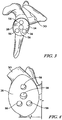
- a drill guide 54 is placed over the concave surface 26 of the glenoid component 20, as seen in FIG. 3 .
- Holes 56 in the drill guide 54 are positioned in alignment with the anchor peg 40 and the stabilising pegs 42.
- a drill is then aligned with the holes 56 in the drill guide 54 to drill out the anchor peg 40 and the stabilising pegs 42.
- the anchor peg 40 and the stabilising pegs 42 are removed by the drill, leaving the body 22 of the glenoid component 20 and bores 58 where the anchor peg 40 and stabilising pegs 42 were implanted during the primary surgical procedure.
- the body 22 of the glenoid component 20 may be removed, leaving the bores 58 in the bone tissue of the patient's scapula 30, as seen in FIG. 4 .
- a secondary glenoid component in the form of a metaglene component 60 may be implanted within the bone tissue of the patient's scapula, as shown in FIG. 5 , during a revision surgical procedure.
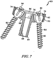
- the metaglene component 60 includes a platform 62 having a stem 64 extending outwardly from its medial surface 66.
- the stem 64 of the metaglene component 60 is configured to be implanted into the surgically-prepared bone tissue of the patient's scapula 30.
- the stem 64 has a bore 68 formed therein.
- the bore 68 extends through the entire length of the stem 64, although it could be embodied as a blind bore.
- An outer annular surface 70 of the platform 62 is tapered inwardly between a lateral surface 76 and the medial surface 66 of the platform 62, the function of which will be described below.
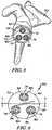
- a number of screw holes 74 extend through the platform 62 of the metaglene component 60.
- the platform 62 shown in FIGS. 6 and 7 has three screw holes 74 extending through the platform 62 which are adapted to be aligned with the bores 58 in the glenoid surface 28.
- Each of the screw holes 74 opens into the medial surface 66 of the platform 62, with its other end opening into the lateral surface 76 of the platform 62.
- Each of the screw holes 74 may be counterbored to accommodate screw heads of compression screws 80 used to secure the metaglene component 60 to the bone tissue of the patient's scapula 30.
- the bore 68 may also be capable of accepting a compression screw 80 in alignment with a bore 58 that was previously occupied by the anchor peg 40 of the primary glenoid component 20.
- each of the screw holes 74 is spaced outwardly from a centre of the platform 62 of the metaglene component 60 at a position between the bore 68 and its tapered outer annular surface 70.
- Each of the screw holes 74 is depicted as being positioned about 120 degrees from an adjacent screw hole 74, but the screw holes 74 may be positioned in any location that corresponds to the placement of the stabilising pegs 42 of the primary glenoid component 20. Still optionally, if the primary glenoid component 20 does not include stabilising pegs 42, the metaglene component 60 need not include screw holes 74.
- the compression screws 80 may be positioned in some or all of the screw holes 74 and/or the bore 68 to secure the metaglene component 60 to the bone tissue of the patient's scapula 30.
- Each of the screws 80 includes a threaded shank 82 having a screw head 84 on an end thereof.
- a diameter of the threaded shank 82 is smaller than a diameter of the lower end of the counterbored screw holes 74 of the metaglene component 60 so that the threaded shank 82 may pass through the entire length of the screw holes 74.
- the screw head 84 has a diameter smaller than the upper end of the counterbored screw holes 74, but larger than the lower end of the counterbored screw holes 74. As such, the screw heads 84 of the compression screws 80 are contained in the upper end of the counterbored screw holes 74 when installed in the metaglene component 60.
- the metaglene component 60 may be constructed with an implant-grade biocompatible metal, although other materials may also be used.
- metals include cobalt, including cobalt alloys such as a cobalt chromium alloy, titanium, including titanium alloys such as a Ti6Al4V alloy, and certain stainless steels.
- Such a metallic metaglene component 60 may also be coated with a surface treatment, such as hydroxyapatite, to enhance biocompatibility.
- the surfaces of the metaglene component 60 that engage the natural bone, such as the medial surface 66 of platform 62 and an outer surface of the stem 64 may be textured to facilitate securing the component to the bone.
- Such surfaces may also be porous coated to promote bone ingrowth for permanent fixation.
- the compression screws 80 may be constructed with an implant-grade biocompatible metal, although other materials may also be used.
- examples of such materials include cobalt, including cobalt alloys such as a cobalt chromium alloy, titanium, including titanium alloys such as a Ti6Al4V alloy, and certain stainless steels.
- the metaglene component 60 is implanted within the bone tissue of the scapula 30 by positioning the stem 64 of the metaglene component 60 within the bore 58 previously occupied by the anchor peg 40 of the primary glenoid component 20, and thereafter fixing the metaglene component 60 in place by inserting one or more compression screws 80 through the screw holes 74 and driving them into the bone tissue of the patient's scapula 30.
- the screws 80 may be inserted into the screw holes 74 and thereafter implanted within the bores 58 formed in the scapula 30, which were previously occupied by the stabilising pegs 42 of the primary glenoid component 20.
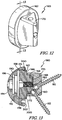
- the reverse shoulder orthopaedic implant includes the metaglene component 60 and a glenosphere component 190, as seen in FIG. 12 .
- the glenosphere component 190 is secured to the glenoid surface 28 of the patient's scapula 30 by the metaglene component 60, which is implanted in the bone tissue of the scapula 30.
- the glenosphere component 190 articulates on a bearing surface of a humeral cup of a humeral prosthesis (not shown).
- the glenosphere component 190 may be similar to that discussed below in relation to FIG. 12 .
- an anatomic bearing similar to the anatomic bearing 220 depicted in FIG. 14 may be secured to the glenoid surface 28 of the patient's scapula 30 by the metaglene component 60, which is implanted in the bone tissue of the scapula 30.
- the anatomic bearing 220 provides a smooth bearing surface upon which a natural or prosthetic humeral head (not shown) articulates.
- the anatomic bearing 220 may be similar to that discussed below in relation to FIG. 14 , or may be any other suitable anatomic bearing.
- An anatomic bearing for use with the metaglene component may be may be constructed with a polymeric material, for example, a polyethylene.
- UHMWPE ultrahigh molecular weight polyethylene
- the metaglene component 60 might optionally be provided in a single "universal" size that accommodates glenosphere components of various sizes.
- a metaglene component 60 may be provided in a single size to accommodate both a 38 mm glenosphere component 190 and a 42 mm glenosphere component 190.
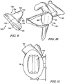
- FIGS. 9 and 10 show a primary polymer keeled glenoid component 120 which includes a body 122 having a first generally convex surface 124 and a second generally concave surface 126 opposite the convex surface 124.
- the convex surface 124 of the body 122 is configured to abut or otherwise contact a prepared glenoid surface 28 of a patient's scapula 30.
- the concave surface 126 of the body 122 provides a smooth bearing surface upon which a natural or prosthetic humeral head (not shown) articulates.
- the keeled glenoid component 120 further includes an anchor or keel 130 extending from the convex surface 124.
- the keel 130 may have a shape that is generally triangular with a base 132 integrally connected to the convex surface 124 and angled sides 134, 136 extending from ends of the base 132 and terminating in a rounded end 138.
- a width of the keel 130 at the base 132 is greater than a width of the keel 130 at the rounded end 138.
- the keel 130 is depicted as having a particular shape, the keel 130 could have any suitable shape.
- the keel 130 is disclosed as being integral with the convex surface 124, the keel 130 may optionally be a separate component that is secured to the convex surface 124.
- the body 122 and the keel 130 may be constructed with a polymeric material, for example, a polyethylene.
- a polymeric material for example, a polyethylene.
- a polyethylene is an ultrahigh molecular weight polyethylene (UHMWPE).
- the glenoid surface 28 of the patient's scapula 30 is prepared and bone shaping tools, such as reamers, saws, drills, burrs, rasps, and the like, are used to shape the glenoid surface 28 to form a cavity that is complementary to the keel 130 of the keeled glenoid component 120.
- the keeled glenoid component 120 may then be implanted within the cavity using bone cement or the like.
- the implanted keeled glenoid component 120 is shown in FIG. 10 .
- a guide having saw slots is positioned over the concave surface 126 of the keeled glenoid component 120, as seen in FIG. 10 .
- a micro saw blade or other appropriate tool may thereafter be positioned within the saw slots, in which the saw removes a portion of the body 122 of the keeled glenoid component 120 and the keel 130 by boring through the keeled glenoid component 120 and the bone tissue of the patient's scapula 30. Only non-affixed portions of the body 122 remain, which can be removed to leave a central void 142 within the glenoid surface 28 of the scapula 30, as seen in FIG. 11 .
- a vaulted component 160 may be implanted within the bone tissue of the patient's scapula 30 during a revision surgical procedure.
- the vaulted component 160 includes a platform 162 having a stem 164 extending outwardly from its medial surface 166.
- the stem 164 of the vaulted component 160 is configured to be secured within a cavity 168 in a vaulted baseplate 170, which is configured to be implanted within the surgically-prepared bone tissue of the patient's scapula 30.
- the stem 164 has a threaded bore 172 formed therein.
- An outer annular surface 174 of the platform 162 is tapered, the function of which will be described below. While the metaglene component 160 and the vaulted baseplate 170 are shown as being separate components, the platform 162 and the vaulted baseplate 170 may be formed integrally as a single piece.
- the vaulted baseplate 170 has a geometry that conforms to the central void 142 formed within the glenoid surface 28 of the scapula 30 during preparation of the glenoid surface 28.
- a number of screw holes 180 extend through the vaulted baseplate 170.
- Each of the screw holes opens into the cavity 168 in the vaulted baseplate 170 and may be counterbored to accommodate screw heads of compression screws 182 used to secure the vaulted component 160 to the bone tissue of the patient's scapula 30.
- upper ends of the screw holes 180 would have a larger diameter than lower ends of the screw holes 180.
- the screw holes 180 and screws 182 are similar to the screw holes 74 and screws 80 of FIGS. 5 to 7 .
- the platform 162 and the vaulted baseplate 170 may be constructed with an implant-grade biocompatible metal, although other materials may also be used.
- metals include cobalt, including cobalt alloys such as a cobalt chromium alloy, titanium, including titanium alloys such as a Ti6Al4V alloy, and certain stainless steels.
- Such a metallic vaulted component 160 may also be coated with a surface treatment, such as hydroxyapatite, to enhance biocompatibility.
- the surfaces of the vaulted component 160 that engage the natural bone, such as the medial surface 166 of platform 162 and the vaulted baseplate 170 may be textured to facilitate securing the component to the bone.
- Such surfaces may also be porous coated to promote bone ingrowth for permanent fixation.
- a glenosphere component 190 may be secured to the platform 162 of the vaulted component 160 in the case when a reverse shoulder orthopaedic implant is necessary, as discussed above.
- the glenosphere component 190 includes a body 192 having a curved lateral surface 194.
- the curved lateral surface 194 of the body 192 provides a smooth bearing surface upon which a bearing surface of a humeral cup (not shown) articulates.
- the lateral bearing surface 194 may be hemi-ellipsoidal in shape. That is, the lateral bearing surface 194 defines the general shape of ellipsoid sliced in half along its longitudinal plane.
- the glenosphere component 190 also includes a substantially flat medial surface 196 opposite its lateral bearing surface 194.
- the medial surface 196 has a tapered bore 198 formed therein.
- Tapered sidewalls 200 defining the bore 198 extend laterally away from the medial surface 196 to a bottom wall 202.
- the tapered outer annular surface 174 of the platform 162 of the vaulted component 160 may be inserted into the tapered bore 198 to engage the sidewalls 200, thereby taper locking the glenosphere component 190 to the vaulted component 160.
- the same or a similar glenosphere component 190 may similarly be secured to the platform 62 of the metaglene component 60 of FIGS. 5 to 7 .
- the metaglene component 60 includes a tapered outer annular surface 70 that forms a taper locking with the tapered bore 198 in the same manner as the tapered outer annular surface 174 of FIG. 13 .
- an anatomic bearing 220 may be secured to the platform 162 of the vaulted component 160 in the case when a reverse shoulder orthopaedic implant is not necessary. Similar to the glenosphere component 190, the anatomic bearing 220 generally includes a tapered bore in a medial surface thereof, in which tapered sidewalls defining the bore engage the tapered outer annular surface 174 of the platform 162 of the vaulted component 160, thereby taper locking the glenosphere anatomic bearing 220 to the vaulted component 160. The anatomic bearing 220 further includes a bearing surface 220 upon which the natural or prosthetic humeral head articulates.
- metaglene components 60, vaulted component 160, a particular glenosphere component 190, and a particular anatomic bearing 220 are depicted, the metaglene components, vaulted components, glenosphere components, and/or anatomic bearings can be varied, and these components can be used with any suitable primary and/or secondary glenoid components.
- revision of a glenoid implant involves both surgical steps related to removal of the primary component and preparation of the bone tissue for implantation of the secondary component.
- the methods disclosed herein provide a system in which removal of a primary glenoid component simultaneously prepares the glenoid surface and the bone tissue of the patient's scapula for re-implantation of a secondary glenoid component.
- the simultaneous removal and preparation may reduce the time necessary to perform the surgical procedure and reduce the number of instruments necessary for the surgical procedure.
- the simultaneous removal and preparation may reduce bone loss because the same voids (e.g. holes or cavities) for a revision procedure, rather than creating new voids.
- the methods may generally include the steps of positioning a tool guide atop an implanted primary glenoid component and penetrating the primary glenoid component with a tool.
- the tool guide provides the surgeon with a guide for the tool such that the tool penetrates and bores through the primary glenoid component and the glenoid surface 28 of the scapula 30 to remove portions of the primary glenoid component that are implanted within the bone tissue of the scapula 30.
- the portions of the primary glenoid component that were implanted within the bone tissue of the scapula 30 have been removed and a remainder of the primary glenoid component, which is unattached, may be removed, thereby leaving a void within the glenoid surface 28 of the scapula 30.
- the void may be formed by any suitable tool, such as for example, a saw or a drill, and may have any geometry, shape, and/or dimension, for example, a cylindrical hole or any other shape that conforms to a geometry, shape, and/or dimension of an anchor within the secondary glenoid component.
- the method further includes the step of implanting a secondary glenoid component within the void.
- a platform system is provided such that the surgeon may determine intra-operatively whether to implant an anatomic secondary glenoid component or a reverse secondary glenoid component regardless of the surgeon's plan prior to the surgical procedure.
- the surgeon may perform trialing to determine whether an anatomic or a reverse secondary glenoid component is necessary.
- the surgeon may additionally or alternatively make this decision based on the extent of damage to the shoulder (e.g. the cuff). For example, if the extent of damage of the shoulder is minimal, the surgeon may decide to implant an anatomic secondary glenoid component. Conversely, if the extent of damage of the shoulder is greater, the surgeon may decide intra-operatively to implant a reverse secondary glenoid component.
- the anatomic and reverse secondary glenoid components may include a single platform including a platform with an anchor that generally conforms in size, shape, and/or dimension to a size, shape, and/or dimension of the void remaining after removal of the primary glenoid component.
- the anchor may be similar in geometry, shape, and/or dimension to the anchor of the primary glenoid component.
- placing the stem 64 of the metaglene component 60 uses the same anatomic landmarks and instrumentation regardless of whether an anatomic or reverse prosthesis is used. As noted above, this provides a common surgical approach (with the possibility of adapting the approach during surgery), a more efficient surgical process, reduces the length of the surgical procedure, and reduces the number of necessary instruments in the operating room (and the chances of a missing instrument).
Description
- The present invention relates generally to orthopaedic implants, and more particularly to, a system for implanting a secondary glenoid prosthesis.
- During the lifetime of a patient, it may be necessary to perform a total shoulder replacement procedure on the patient as a result of, for example, disease or trauma. In a total shoulder replacement procedure, a humeral prosthesis is used to replace the natural head of the patient's humerus. The humeral prosthesis typically includes an elongated stem component that is implanted into the intramedullary canal of the patient's humerus and a hemispherically-shaped prosthetic head component that is secured to the stem component. In such a total shoulder replacement procedure, the natural glenoid surface of the scapula is resurfaced or otherwise replaced with a glenoid component that provides a bearing surface upon which the prosthetic head component of the humeral prosthesis articulates.
- However, in some cases the patient's natural shoulder, including its soft tissue, has degenerated to a severe degree of joint instability and pain. In many such cases, it may be necessary to change the mechanics of the shoulder. Reverse shoulder implants are used to do so. As its name suggests, a reverse shoulder implant reverses the anatomy, or structure, of the healthy shoulder. In particular, a reverse shoulder implant is designed such that the prosthetic head (i.e. the "ball" in the ball-and-socket joint) known as a glenosphere component is secured to the patient's scapula, with the corresponding concave bearing (i.e. the "socket" in the ball-and-socket joint) known as a humeral cup being secured to the patient's humerus. Such a reverse configuration allows the patient's deltoid muscle, which is one of the larger and stronger shoulder muscles, to raise the arm.
-
US-A-2012/253467 discloses a shoulder arthroplasty system which includes a baseplate for fastening to a patient's scapula, and first and second glenoid components which can be attached to the baseplate. A first glenoid component has a concave surface for articulation with a humeral component. A second glenoid component is a glenosphere component which has a convex surface for articulation with a socket component on the patient's humerus. - The invention provides a system for implanting a shoulder prosthesis in a scapula of a patient, as defined in claim 1.
- Optionally, the system includes an anatomic bearing and also a glenosphere component, in which each of them individually is suitable for use in the secondary glenoid component.
- The system can be used in a method of implanting a shoulder prosthesis in a scapula of a patient includes the step of placing a guide over a primary glenoid component previously implanted within the scapula of the patient. The method can include removing the primary glenoid component from the scapula and preparing the scapula for implantation of a secondary glenoid component, in which the removing and preparing steps occur simultaneously.
- Optionally, the removing step may include using a tool to penetrate the primary glenoid and into the glenoid surface of the scapula. The removing step may further include creating a void in the bone tissue of the scapula that is at least as large as and occupies at least as much space as an anchor extending from the primary glenoid component and which implants the primary glenoid component within the bone tissue of the scapula, thereby eliminating the anchor. Still further, the removing step may include the step of removing unanchored primary glenoid component from the bone tissue of the scapula.
- Optionally, the scapula may be prepared for implantation of the secondary glenoid component by creation of the void in the bone surface of the scapula.
- Optionally, the method may further include the steps of providing a secondary glenoid component comprising an anchor having a geometry that generally conforms to a geometry of the void in the bone tissue of the scapula and implanting the anchor of the secondary glenoid component within the void.
- Optionally, the method may further include the step of assessing the extent of damage to the shoulder of the patient. If the extent of damage is at a first level, the method may include the step of implanting an anchor of an anatomic secondary glenoid component within the void. Alternatively, if the extent of the damage is at a second level, the method may include the step of implanting an anchor of a reverse secondary glenoid component within the void. The anchor of the anatomic secondary glenoid component and the anchor
- of the reverse secondary glenoid have geometries that generally conform to a geometry of the void.
- The system can be used in a method of implanting a shoulder prosthesis in a scapula of a patient includes the step of creating a void in the scapula of the patient by penetrating the primary glenoid component, in which the void encompasses an area within the bone tissue of the scapula occupied by an anchor extending from the primary glenoid component and implanted within the scapula of the patient. The method further includes the steps of removing fragments of the primary glenoid component that are no longer anchored to the bone tissue of the scapula after the step of creating a void and implanting a secondary glenoid component within the void.
- Optionally, the secondary component may include a platform having a lateral surface and an opposite medial surface and adapted to contact the scapula of the patient. The platform may further include at least one anchor extending from the medial surface of the platform, in which the anchor is adapted to be implanted within the void.
- Optionally, the anchor may be in the form of a peg extending outwardly from a central portion of the medial surface of the platform. Alternatively, the anchor may be in the form of a keel extending outwardly from the medial surface of the platform.
- Optionally, the method may further include assessing the extent of damage to the shoulder of the patient during surgery. If the extent of the damage is at a first level, the method may further include implanting an anchor of an anatomic secondary glenoid component within the void. Alternatively, if the extent of the damage is at a second level, the method may further include implanting an anchor of a reverse secondary glenoid component within the void. The anchor of anatomic secondary glenoid component and the anchor of the reverse secondary glenoid have geometries that generally conform to a geometry of the void. In addition, the assessing step allows a surgeon to change plans intra-operatively between anatomic and reverse secondary glenoid components.
- The step of creating the void further includes the steps of placing a guide over a primary glenoid component previously implanted within the scapula of the patient and removing the primary glenoid component from the scapula. The step of creating the void still further may include the step of preparing the scapula for implantation of a secondary glenoid component, in which the removing and preparing steps occur simultaneously.
- The scapula is prepared for implantation of the secondary glenoid component by creation of the void in the glenoid surface of the scapula.
- The method further includes the steps of providing the secondary glenoid component comprising an anchor having dimensions that conform to dimensions of the void in the glenoid surface of the scapula and implanting the anchor of the secondary glenoid component within the void.
- The system can be used in a method of implanting a shoulder prosthesis in a scapula of a patient includes the steps of accessing the bone tissue of the patient's scapula, creating a void within the bone tissue of the patient's scapula, and assessing the extent of damage to the shoulder of the patient. If the extent of the damage is at a first level, the method may further include the step of implanting a first anchor of an anatomic glenoid component within the void. If the extent of the damage is at a second level, the method may further include the step of implanting a second anchor of a reverse glenoid component within the void. The first anchor of the anatomic glenoid component and the second anchor of the reverse secondary glenoid have geometries that conform generally conform to a geometry of the void.
- The method further includes the steps of placing a guide over a primary glenoid component previously implanted within the scapula of the patient and removing the primary glenoid component from the scapula. The method further includes the step of preparing the scapula for implantation of a secondary glenoid component, in which the removing and preparing steps occur simultaneously.
- Optionally, the anatomic glenoid component and the reverse glenoid component may be part of a platform system. The platform system may include a platform having an anchor extending therefrom and a bearing attachable to the platform and having a bearing surface that forms an articulation surface for articulation of a humeral head, in which the bearing forms the anatomic glenoid component. The platform system may further include a glenosphere component attachable to the platform and having a surface that articulates upon a bearing surface of a humeral cup.
- Optionally, the method may further include the step of determining intra-operatively whether to implant an anatomic secondary glenoid component or a reverse anatomic glenoid component.
- Optionally, the determining step may be undertaken after implanting the anchor of the platform within the bone tissue of the scapula and, once the determining step is completed, either the bearing or the glenosphere component may be attached to the platform.
- The invention is described below by way of example with reference to the accompanying drawings, in which:
-
FIG. 1 is a perspective view of a primary glenoid component implanted within bone tissue of a patient's scapula. -
FIG. 2 is a perspective view of a primary glenoid component in the form of a pegged glenoid component for implantation within the bone tissue of the patient's scapula. -
FIG. 3 is a perspective view similar to the view ofFIG. 1 with a drill guide positioned on top of a concave bearing surface of the primary glenoid component ofFIGS. 1 and 2 . -
FIG. 4 is an enlarged perspective view of the glenoid surface of the patient's scapula after pegs of the primary glenoid component have been drilled out, leaving bores in the bone tissue of the patient's scapula, and after a remainder of the primary glenoid component has been removed. -
FIG. 5 is a perspective view of a metaglene component of a secondary glenoid component implanted within the bone tissue of the patient's scapula. -
FIG. 6 is a top elevational view of the metaglene component ofFIG. 5 . -
FIG. 7 is a cross-sectional view taken generally along the lines 7-7 ofFIG. 6 , showing a central bore extending through a stem of the metaglene component and compression screws extending through a platform of the metaglene component. -
FIG. 8 is a partial cross-sectional view similar to the view ofFIG. 7 , depicting the metaglene component implanted within the bone tissue of the patient's scapula. -
FIG. 9 is a perspective view of a primary glenoid component in the form of a keeled glenoid component for implantation within the bone tissue of a patient's scapula. -
FIG. 10 is a perspective view of the primary glenoid component ofFIG. 9 implanted within the bone tissue of the patient's scapula and a saw guide positioned on top of a concave bearing surface of the primary glenoid component. -
FIG. 11 is a perspective view of the glenoid surface of the patient's scapula after a keel of the primary glenoid component has been sawed out, leaving a void in the bone tissue of the patient's scapula, and after a reminder of the primary glenoid component has been removed. -
FIG. 12 is a perspective view of a vaulted component of a secondary glenoid component for implantation within the void ofFIG. 11 . -
FIG. 13 is a cross-sectional view taken generally along the lines 13-13 ofFIG. 12 and showing a glenosphere component secured to the vaulted component ofFIG. 12 . -
FIG. 14 is a secondary glenoid component having an anatomic bearing secured to the vaulted component. - Terms representing anatomical references, such as anterior, posterior, medial, lateral, superior and inferior, may be used throughout this document to refer to both the orthopaedic implants and instruments described herein and a patient's natural anatomy. Such terms have well-understood meanings in both the study of anatomy and the field of orthopaedics. Use of such anatomical reference terms in this document is intended to be consistent with their well-understood meanings unless noted otherwise.
- Referring now to the drawings,
FIGS. 1 and 2 show a primarypolymer glenoid component 20 which includes abody 22 having a first generallyconvex surface 24 and a second generally concavesurface 26 opposite theconvex surface 24. Theconvex surface 24 of thebody 22 is configured to abut or otherwise contact a preparedglenoid surface 28 of a patient'sscapula 30, as will be discussed below. Theconcave surface 26 of thebody 22 provides a smooth bearing surface upon which a natural or prosthetic humeral head (not shown) articulates. - The
glenoid component 20 also includes ananchor peg 40 and a number of stabilising pegs 42 secured to and extending generally orthogonal to theconvex surface 24 of thebody 22. As shown inFIGS. 1 and 2 , theanchor peg 40 includes a taperedhead 48 that functions as a lead-in to facilitate insertion into a hole drilled or otherwise formed in aglenoid surface 28. The anchor peg 40 also includes a plurality of flexibleradial fins 50 extending outwardly from atop end 52 of theanchor peg 40. Theglenoid component 20 is discussed inUS-6699289 andUS-6911047 . - The
glenoid component 20 may be constructed of a polymeric material, for example, a polyethylene. One example of a suitable polyethylene is ultrahigh molecular weight polyethylene (UHMWPE). - During a primary surgical procedure, the
glenoid surface 28 of the patient'sscapula 30 is prepared and bores are drilled into the preparedglenoid surface 28 of the patient'sscapula 30. Theprimary glenoid component 20 is thereafter implanted within the bone tissue of thescapula 30 with theconvex surface 24 of thebody 22 abutting or otherwise contacting the preparedglenoid surface 28, with theanchor peg 40 and stabilising pegs 42 extending into the bores. While theradial fins 50 aid in retaining theanchor peg 40 within a respective bore, bone cement may alternatively or additionally be used. The installedglenoid component 20 is shown inFIG. 1 . Theglenoid component 20 may alternatively be implanted in any suitable manner. - During a revision surgical procedure, a
drill guide 54 is placed over theconcave surface 26 of theglenoid component 20, as seen inFIG. 3 .Holes 56 in thedrill guide 54 are positioned in alignment with theanchor peg 40 and the stabilising pegs 42. A drill is then aligned with theholes 56 in thedrill guide 54 to drill out theanchor peg 40 and the stabilising pegs 42. In this manner, theanchor peg 40 and the stabilising pegs 42 are removed by the drill, leaving thebody 22 of theglenoid component 20 and bores 58 where theanchor peg 40 and stabilising pegs 42 were implanted during the primary surgical procedure. Thebody 22 of theglenoid component 20 may be removed, leaving thebores 58 in the bone tissue of the patient'sscapula 30, as seen inFIG. 4 . - A secondary glenoid component in the form of a
metaglene component 60, as shown inFIGS. 6 and7 , may be implanted within the bone tissue of the patient's scapula, as shown inFIG. 5 , during a revision surgical procedure. Themetaglene component 60 includes aplatform 62 having astem 64 extending outwardly from itsmedial surface 66. Thestem 64 of themetaglene component 60 is configured to be implanted into the surgically-prepared bone tissue of the patient'sscapula 30. Thestem 64 has abore 68 formed therein. Thebore 68 extends through the entire length of thestem 64, although it could be embodied as a blind bore. An outerannular surface 70 of theplatform 62 is tapered inwardly between alateral surface 76 and themedial surface 66 of theplatform 62, the function of which will be described below. - As shown in
FIGS. 6 and7 , a number of screw holes 74 extend through theplatform 62 of themetaglene component 60. For example, theplatform 62 shown inFIGS. 6 and7 has threescrew holes 74 extending through theplatform 62 which are adapted to be aligned with thebores 58 in theglenoid surface 28. Each of the screw holes 74 opens into themedial surface 66 of theplatform 62, with its other end opening into thelateral surface 76 of theplatform 62. Each of the screw holes 74 may be counterbored to accommodate screw heads of compression screws 80 used to secure themetaglene component 60 to the bone tissue of the patient'sscapula 30. As such, upper ends of the screw holes 74 would have a larger diameter than lower ends of the screw holes 74. Thebore 68 may also be capable of accepting acompression screw 80 in alignment with abore 58 that was previously occupied by theanchor peg 40 of theprimary glenoid component 20. - In the device shown in
FIGS. 6 and7 , each of the screw holes 74 is spaced outwardly from a centre of theplatform 62 of themetaglene component 60 at a position between thebore 68 and its tapered outerannular surface 70. Each of the screw holes 74 is depicted as being positioned about 120 degrees from anadjacent screw hole 74, but the screw holes 74 may be positioned in any location that corresponds to the placement of the stabilising pegs 42 of theprimary glenoid component 20. Still optionally, if theprimary glenoid component 20 does not include stabilisingpegs 42, themetaglene component 60 need not include screw holes 74. - As shown in
FIGS 5 to 8 , the compression screws 80 may be positioned in some or all of the screw holes 74 and/or thebore 68 to secure themetaglene component 60 to the bone tissue of the patient'sscapula 30. Each of thescrews 80 includes a threadedshank 82 having ascrew head 84 on an end thereof. A diameter of the threadedshank 82 is smaller than a diameter of the lower end of the counterbored screw holes 74 of themetaglene component 60 so that the threadedshank 82 may pass through the entire length of the screw holes 74. Thescrew head 84, on the other hand, has a diameter smaller than the upper end of the counterbored screw holes 74, but larger than the lower end of the counterbored screw holes 74. As such, the screw heads 84 of the compression screws 80 are contained in the upper end of the counterbored screw holes 74 when installed in themetaglene component 60. - The
metaglene component 60 may be constructed with an implant-grade biocompatible metal, although other materials may also be used. Examples of such metals include cobalt, including cobalt alloys such as a cobalt chromium alloy, titanium, including titanium alloys such as a Ti6Al4V alloy, and certain stainless steels. Such ametallic metaglene component 60 may also be coated with a surface treatment, such as hydroxyapatite, to enhance biocompatibility. Moreover, the surfaces of themetaglene component 60 that engage the natural bone, such as themedial surface 66 ofplatform 62 and an outer surface of thestem 64 may be textured to facilitate securing the component to the bone. Such surfaces may also be porous coated to promote bone ingrowth for permanent fixation. - Like the
metaglene component 60, the compression screws 80 may be constructed with an implant-grade biocompatible metal, although other materials may also be used. Examples of such materials include cobalt, including cobalt alloys such as a cobalt chromium alloy, titanium, including titanium alloys such as a Ti6Al4V alloy, and certain stainless steels. - As seen in
FIG. 5 , themetaglene component 60 is implanted within the bone tissue of thescapula 30 by positioning thestem 64 of themetaglene component 60 within thebore 58 previously occupied by theanchor peg 40 of theprimary glenoid component 20, and thereafter fixing themetaglene component 60 in place by inserting one or more compression screws 80 through the screw holes 74 and driving them into the bone tissue of the patient'sscapula 30. In particular, thescrews 80 may be inserted into the screw holes 74 and thereafter implanted within thebores 58 formed in thescapula 30, which were previously occupied by the stabilising pegs 42 of theprimary glenoid component 20. - Depending on the extent of damage to the shoulder, for example, the cuff, bone tissue, etc. a reverse shoulder orthopaedic implant may be necessary. The reverse shoulder orthopaedic implant includes the
metaglene component 60 and aglenosphere component 190, as seen inFIG. 12 . Theglenosphere component 190 is secured to theglenoid surface 28 of the patient'sscapula 30 by themetaglene component 60, which is implanted in the bone tissue of thescapula 30. Theglenosphere component 190 articulates on a bearing surface of a humeral cup of a humeral prosthesis (not shown). Theglenosphere component 190 may be similar to that discussed below in relation toFIG. 12 . - In other instances, during a revision surgical procedure, the damage to the shoulder, for example, the cuff, bone tissue, etc. may not require a reverse shoulder orthopaedic implant. As such, an anatomic bearing similar to the
anatomic bearing 220 depicted inFIG. 14 , may be secured to theglenoid surface 28 of the patient'sscapula 30 by themetaglene component 60, which is implanted in the bone tissue of thescapula 30. Theanatomic bearing 220 provides a smooth bearing surface upon which a natural or prosthetic humeral head (not shown) articulates. Theanatomic bearing 220 may be similar to that discussed below in relation toFIG. 14 , or may be any other suitable anatomic bearing. An anatomic bearing for use with the metaglene component may be may be constructed with a polymeric material, for example, a polyethylene. One example of a suitable polyethylene is ultrahigh molecular weight polyethylene (UHMWPE). - Unlike the
glenosphere component 190 and theanatomic bearing 220 that may be provided in various sizes to provide the flexibility necessary to conform to varying anatomies from patient to patient, themetaglene component 60 might optionally be provided in a single "universal" size that accommodates glenosphere components of various sizes. For example, ametaglene component 60 may be provided in a single size to accommodate both a 38mm glenosphere component 190 and a 42mm glenosphere component 190. -
FIGS. 9 and 10 show a primary polymer keeledglenoid component 120 which includes abody 122 having a first generallyconvex surface 124 and a second generallyconcave surface 126 opposite theconvex surface 124. Theconvex surface 124 of thebody 122 is configured to abut or otherwise contact a preparedglenoid surface 28 of a patient'sscapula 30. Theconcave surface 126 of thebody 122 provides a smooth bearing surface upon which a natural or prosthetic humeral head (not shown) articulates. - The keeled
glenoid component 120 further includes an anchor orkeel 130 extending from theconvex surface 124. Thekeel 130 may have a shape that is generally triangular with a base 132 integrally connected to theconvex surface 124 andangled sides base 132 and terminating in arounded end 138. A width of thekeel 130 at thebase 132 is greater than a width of thekeel 130 at therounded end 138. While thekeel 130 is depicted as having a particular shape, thekeel 130 could have any suitable shape. While thekeel 130 is disclosed as being integral with theconvex surface 124, thekeel 130 may optionally be a separate component that is secured to theconvex surface 124. - The
body 122 and thekeel 130 may be constructed with a polymeric material, for example, a polyethylene. One example of a suitable polyethylene is an ultrahigh molecular weight polyethylene (UHMWPE). - During a primary surgical procedure, the
glenoid surface 28 of the patient'sscapula 30 is prepared and bone shaping tools, such as reamers, saws, drills, burrs, rasps, and the like, are used to shape theglenoid surface 28 to form a cavity that is complementary to thekeel 130 of the keeledglenoid component 120. The keeledglenoid component 120 may then be implanted within the cavity using bone cement or the like. The implanted keeledglenoid component 120 is shown inFIG. 10 . - During a revision surgical procedure, a guide having saw slots is positioned over the
concave surface 126 of the keeledglenoid component 120, as seen inFIG. 10 . A micro saw blade or other appropriate tool may thereafter be positioned within the saw slots, in which the saw removes a portion of thebody 122 of the keeledglenoid component 120 and thekeel 130 by boring through the keeledglenoid component 120 and the bone tissue of the patient'sscapula 30. Only non-affixed portions of thebody 122 remain, which can be removed to leave acentral void 142 within theglenoid surface 28 of thescapula 30, as seen inFIG. 11 . - A vaulted
component 160, as seen inFIGS. 12 and 13 may be implanted within the bone tissue of the patient'sscapula 30 during a revision surgical procedure. The vaultedcomponent 160 includes aplatform 162 having astem 164 extending outwardly from itsmedial surface 166. Thestem 164 of the vaultedcomponent 160 is configured to be secured within acavity 168 in a vaultedbaseplate 170, which is configured to be implanted within the surgically-prepared bone tissue of the patient'sscapula 30. Thestem 164 has a threadedbore 172 formed therein. An outerannular surface 174 of theplatform 162 is tapered, the function of which will be described below. While themetaglene component 160 and the vaultedbaseplate 170 are shown as being separate components, theplatform 162 and the vaultedbaseplate 170 may be formed integrally as a single piece. - The vaulted
baseplate 170 has a geometry that conforms to thecentral void 142 formed within theglenoid surface 28 of thescapula 30 during preparation of theglenoid surface 28. As shown inFIGS. 12 and 13 , a number of screw holes 180 extend through the vaultedbaseplate 170. Each of the screw holes opens into thecavity 168 in the vaultedbaseplate 170 and may be counterbored to accommodate screw heads ofcompression screws 182 used to secure the vaultedcomponent 160 to the bone tissue of the patient'sscapula 30. As such, upper ends of the screw holes 180 would have a larger diameter than lower ends of the screw holes 180. The screw holes 180 andscrews 182 are similar to the screw holes 74 and screws 80 ofFIGS. 5 to 7 . - The
platform 162 and the vaultedbaseplate 170 may be constructed with an implant-grade biocompatible metal, although other materials may also be used. Examples of such metals include cobalt, including cobalt alloys such as a cobalt chromium alloy, titanium, including titanium alloys such as a Ti6Al4V alloy, and certain stainless steels. Such a metallic vaultedcomponent 160 may also be coated with a surface treatment, such as hydroxyapatite, to enhance biocompatibility. Moreover, the surfaces of the vaultedcomponent 160 that engage the natural bone, such as themedial surface 166 ofplatform 162 and the vaultedbaseplate 170 may be textured to facilitate securing the component to the bone. Such surfaces may also be porous coated to promote bone ingrowth for permanent fixation. - A
glenosphere component 190 may be secured to theplatform 162 of the vaultedcomponent 160 in the case when a reverse shoulder orthopaedic implant is necessary, as discussed above. Theglenosphere component 190 includes abody 192 having a curvedlateral surface 194. The curvedlateral surface 194 of thebody 192 provides a smooth bearing surface upon which a bearing surface of a humeral cup (not shown) articulates. Thelateral bearing surface 194 may be hemi-ellipsoidal in shape. That is, thelateral bearing surface 194 defines the general shape of ellipsoid sliced in half along its longitudinal plane. - The
glenosphere component 190 also includes a substantially flatmedial surface 196 opposite itslateral bearing surface 194. Themedial surface 196 has a taperedbore 198 formed therein.Tapered sidewalls 200 defining thebore 198 extend laterally away from themedial surface 196 to abottom wall 202. The tapered outerannular surface 174 of theplatform 162 of the vaultedcomponent 160 may be inserted into the tapered bore 198 to engage thesidewalls 200, thereby taper locking theglenosphere component 190 to the vaultedcomponent 160. - The same or a
similar glenosphere component 190 may similarly be secured to theplatform 62 of themetaglene component 60 ofFIGS. 5 to 7 . As noted above, themetaglene component 60 includes a tapered outerannular surface 70 that forms a taper locking with thetapered bore 198 in the same manner as the tapered outerannular surface 174 ofFIG. 13 . - Referring to
FIG. 14 , ananatomic bearing 220 may be secured to theplatform 162 of the vaultedcomponent 160 in the case when a reverse shoulder orthopaedic implant is not necessary. Similar to theglenosphere component 190, theanatomic bearing 220 generally includes a tapered bore in a medial surface thereof, in which tapered sidewalls defining the bore engage the tapered outerannular surface 174 of theplatform 162 of the vaultedcomponent 160, thereby taper locking the glenosphereanatomic bearing 220 to the vaultedcomponent 160. Theanatomic bearing 220 further includes abearing surface 220 upon which the natural or prosthetic humeral head articulates. - While a
particular metaglene component 60, a particular vaultedcomponent 160, aparticular glenosphere component 190, and a particularanatomic bearing 220 are depicted, the metaglene components, vaulted components, glenosphere components, and/or anatomic bearings can be varied, and these components can be used with any suitable primary and/or secondary glenoid components. - Typically, revision of a glenoid implant involves both surgical steps related to removal of the primary component and preparation of the bone tissue for implantation of the secondary component. The methods disclosed herein provide a system in which removal of a primary glenoid component simultaneously prepares the glenoid surface and the bone tissue of the patient's scapula for re-implantation of a secondary glenoid component. The simultaneous removal and preparation may reduce the time necessary to perform the surgical procedure and reduce the number of instruments necessary for the surgical procedure. In addition, the simultaneous removal and preparation may reduce bone loss because the same voids (e.g. holes or cavities) for a revision procedure, rather than creating new voids.
- The methods, as disclosed above, may generally include the steps of positioning a tool guide atop an implanted primary glenoid component and penetrating the primary glenoid component with a tool. The tool guide provides the surgeon with a guide for the tool such that the tool penetrates and bores through the primary glenoid component and the
glenoid surface 28 of thescapula 30 to remove portions of the primary glenoid component that are implanted within the bone tissue of thescapula 30. As such, once the surgeon has finished, the portions of the primary glenoid component that were implanted within the bone tissue of thescapula 30 have been removed and a remainder of the primary glenoid component, which is unattached, may be removed, thereby leaving a void within theglenoid surface 28 of thescapula 30. When a void is referenced with respect to removing the primary glenoid component, it should be understood that the void may be formed by any suitable tool, such as for example, a saw or a drill, and may have any geometry, shape, and/or dimension, for example, a cylindrical hole or any other shape that conforms to a geometry, shape, and/or dimension of an anchor within the secondary glenoid component. - The method further includes the step of implanting a secondary glenoid component within the void. During the surgical procedure, a platform system is provided such that the surgeon may determine intra-operatively whether to implant an anatomic secondary glenoid component or a reverse secondary glenoid component regardless of the surgeon's plan prior to the surgical procedure.
- After the primary glenoid component is removed, the surgeon may perform trialing to determine whether an anatomic or a reverse secondary glenoid component is necessary. The surgeon may additionally or alternatively make this decision based on the extent of damage to the shoulder (e.g. the cuff). For example, if the extent of damage of the shoulder is minimal, the surgeon may decide to implant an anatomic secondary glenoid component. Conversely, if the extent of damage of the shoulder is greater, the surgeon may decide intra-operatively to implant a reverse secondary glenoid component.
- As noted above, a platform system is provided that allows a surgeon to determine intra-operatively between implantation of an anatomic glenoid and a reverse glenoid. In particular, the anatomic and reverse secondary glenoid components may include a single platform including a platform with an anchor that generally conforms in size, shape, and/or dimension to a size, shape, and/or dimension of the void remaining after removal of the primary glenoid component. Further, the anchor may be similar in geometry, shape, and/or dimension to the anchor of the primary glenoid component. As shown in
FIGS. 7 and8 , placing thestem 64 of themetaglene component 60 uses the same anatomic landmarks and instrumentation regardless of whether an anatomic or reverse prosthesis is used. As noted above, this provides a common surgical approach (with the possibility of adapting the approach during surgery), a more efficient surgical process, reduces the length of the surgical procedure, and reduces the number of necessary instruments in the operating room (and the chances of a missing instrument). - While particular primary and secondary glenoid components are depicted, these components can be varied. Examples of suitable secondary glenoid components are disclosed in
US-8231683 andUS-A-2012/0239156 .
Claims (2)
- A system for implanting a shoulder prosthesis in a scapula of a patient, comprising:(a) a primary glenoid component (20; 120) including an anchor (40; 130) adapted to be implanted within the scapula of the patient in a primary surgical procedure,(b) a second glenoid component (60; 160) adapted to be implanted within the scapula of the patient and including:characterised in that the second glenoid component is a secondary glenoid component which is adapted to be implanted within the scapula of the patient in a revision surgical procedure, and the system includes a tool guide (54) which can be positioned over the primary glenoid component when it is implanted in a patient's glenoid, for guiding a tool to penetrate and bore through the primary glenoid component and the glenoid surface of the scapula to remove the anchor portion of the primary glenoid component which is implanted in the patient's glenoid,a platform (62; 162) having an anchor (64; 164) extending therefrom, andat least one of an anatomic bearing (220) and a glenosphere component (190) which can be attached to the platform, the anatomic bearing having a smooth bearing surface upon which a natural or prosthetic humeral head can articulate, and the glenosphere component having a surface that articulates upon a bearing surface of a humeral cup and which forms a reverse glenoid component, in which the geometry and shape of the anchor of the second glenoid component are similar to the geometry and shape of the anchor of the primary glenoid component,
in which the similarities between the geometry and shape of the anchor of the second glenoid component and the geometry and shape of the anchor of the primary glenoid component are such that the anchor of the second glenoid component can be received in the cavity within the patient's glenoid which results from the removal of the anchor portion of the primary glenoid component when performed using the tool guide. - The system of claim 1, in which the system includes an anatomic bearing (220) and also a glenosphere component (190), in which each of them individually is suitable for use in the second glenoid component (60; 160).
Applications Claiming Priority (1)
| Application Number | Priority Date | Filing Date | Title |
|---|---|---|---|
| US13/796,793 US9044330B2 (en) | 2013-03-12 | 2013-03-12 | System and method for implanting a secondary glenoid prosthesis |
Publications (2)
| Publication Number | Publication Date |
|---|---|
| EP2777626A1 EP2777626A1 (en) | 2014-09-17 |
| EP2777626B1 true EP2777626B1 (en) | 2017-02-08 |
Family
ID=50235938
Family Applications (1)
| Application Number | Title | Priority Date | Filing Date |
|---|---|---|---|
| EP14157143.0A Active EP2777626B1 (en) | 2013-03-12 | 2014-02-28 | System for implanting a secondary glenoid prosthesis |
Country Status (6)
| Country | Link |
|---|---|
| US (4) | US9044330B2 (en) |
| EP (1) | EP2777626B1 (en) |
| JP (1) | JP6529717B2 (en) |
| CN (1) | CN104042367B (en) |
| AU (1) | AU2014201048B2 (en) |
| IN (1) | IN2014DE00466A (en) |
Families Citing this family (28)
| Publication number | Priority date | Publication date | Assignee | Title |
|---|---|---|---|---|
| US20230080207A1 (en) | 2005-02-25 | 2023-03-16 | Shoulder Innovations, Inc. | Methods and devices for less invasive glenoid replacement |
| US9662126B2 (en) | 2009-04-17 | 2017-05-30 | Arthrosurface Incorporated | Glenoid resurfacing system and method |
| WO2012058355A1 (en) * | 2010-10-29 | 2012-05-03 | The Cleveland Clinic Foundation | System of preoperative planning and provision of patient-specific surgical aids |
| FR2971144A1 (en) * | 2011-02-08 | 2012-08-10 | Tornier Sa | GLENOIDAL IMPLANT FOR SHOULDER PROSTHESIS AND SURGICAL KIT |
| GB201105243D0 (en) | 2011-03-29 | 2011-05-11 | Depuy Ireland | An implant |
| EP2630935B1 (en) * | 2012-02-27 | 2014-12-31 | Arthrex, Inc. | Glenoid extension block |
| US9398928B2 (en) | 2012-09-28 | 2016-07-26 | DePuy Synthes Products, Inc. | Adjustable height arthroplasty plate |
| US9044330B2 (en) | 2013-03-12 | 2015-06-02 | DePuy Synthes Products, Inc. | System and method for implanting a secondary glenoid prosthesis |
| CA2906631C (en) * | 2013-03-15 | 2018-05-01 | Robert Craig COHEN | Unicondylar tibial knee implant |
| US9962266B2 (en) | 2015-09-11 | 2018-05-08 | Deltoid, Llc | Arthroplasty components |
| US10433969B2 (en) | 2013-12-30 | 2019-10-08 | United Orthopedic Corp. | Arthroplasty implants and methods for orienting joint prosthesis |
| US9681960B2 (en) | 2014-05-16 | 2017-06-20 | Howmedica Osteonics Corp. | Guides for fracture system |
| US10575968B2 (en) | 2014-05-16 | 2020-03-03 | Howmedica Osteonics Corp. | Guides for fracture system |
| US9597190B2 (en) | 2015-01-15 | 2017-03-21 | DePuy Synthes Products, Inc. | Modular reverse shoulder orthopaedic implant and method of implanting the same |
| USD835276S1 (en) | 2015-09-11 | 2018-12-04 | United Orthopedic Corporation | Keeled glenoid |
| JP6703144B2 (en) | 2016-02-28 | 2020-06-03 | コンソーシアム オブ フォーカスド オーソペディスツ, エルエルシー | Shoulder arthroplasty implant system |
| US11833055B2 (en) | 2016-02-28 | 2023-12-05 | Integrated Shoulder Collaboration, Inc. | Shoulder arthroplasty implant system |
| CA3032645A1 (en) * | 2016-08-01 | 2018-02-08 | Exactech, Inc. | Platform rtsa glenoid prosthesis with modular attachments capable of improving initial fixation, fracture reconstructions, and joint biomechanics |
| US11510785B2 (en) | 2017-04-25 | 2022-11-29 | Biomet Manufacturing, Llc | Augmented glenoid with groove |
| CN207648424U (en) * | 2017-07-17 | 2018-07-24 | 手持产品公司 | Equipment holding mechanism |
| US10813769B2 (en) | 2018-07-24 | 2020-10-27 | DePuy Synthes Products, Inc. | Baseplate of a modular shoulder joint prosthesis and related methods for implanting the same |
| JP2022526241A (en) | 2019-03-11 | 2022-05-24 | ショルダー・イノベーションズ・インコーポレイテッド | All reverse shoulder system and method |
| GB2596006B (en) | 2019-03-12 | 2022-11-30 | Arthrosurface Inc | Humeral and glenoid articular surface implant systems and methods |
| US11571310B2 (en) | 2019-04-03 | 2023-02-07 | Catalyst Orthoscience Inc. | Stemmed implant |
| AU2020328486B2 (en) | 2019-08-09 | 2024-01-25 | Howmedica Osteonics Corp. | Apparatuses and methods for implanting glenoid prostheses |
| US20230096120A1 (en) * | 2020-03-02 | 2023-03-30 | Raphael S.F. Longobardi, Llc | Universal shoulder prosthesis system and tools |
| CN111281620A (en) * | 2020-03-30 | 2020-06-16 | 北京市春立正达医疗器械股份有限公司 | Glenoid prosthesis applied to total shoulder joint replacement |
| US11918476B1 (en) * | 2022-09-14 | 2024-03-05 | ARCA By OrthoAgile, LLC | Glenoid replacement system and methods of implanting said glenoid replacement |
Family Cites Families (36)
| Publication number | Priority date | Publication date | Assignee | Title |
|---|---|---|---|---|
| FR2652498B1 (en) * | 1989-10-04 | 1997-12-26 | Medinov | MODULAR ASSEMBLY FOR SHOULDER PROSTHESIS. |
| US6503253B1 (en) | 1993-11-16 | 2003-01-07 | Synvasive Technology, Inc. | Surgical saw blade |
| US5163964A (en) * | 1991-06-26 | 1992-11-17 | Zimmer, Inc. | Orthopaedic prosthesis with access in collar |
| US5961555A (en) | 1998-03-17 | 1999-10-05 | Huebner; Randall J. | Modular shoulder prosthesis |
| US5593448A (en) | 1995-11-14 | 1997-01-14 | Osteonics Corp. | Glenoid component for shoulder prosthesis and implant method |
| US6379386B1 (en) | 1997-09-09 | 2002-04-30 | Stryker Technologies Corporation | Anatomic glenoid shoulder prosthesis together with methods and tools for implanting same |
| JP4633212B2 (en) * | 1998-11-13 | 2011-02-16 | アキュームド・インク | Shoulder joint prosthesis |
| FR2802799B1 (en) | 1999-12-23 | 2002-08-16 | Depuy France | SHOULDER PROSTHESIS KIT |
| US6364910B1 (en) * | 2001-07-11 | 2002-04-02 | Biomet, Inc. | Method and apparatus for use of a glenoid component |
| US7867236B2 (en) | 2003-12-30 | 2011-01-11 | Zimmer, Inc. | Instruments and methods for preparing a joint articulation surface for an implant |
| ATE503442T1 (en) * | 2004-05-19 | 2011-04-15 | Zimmer Gmbh | GLENOID ANCHORAGE |
| US7806898B2 (en) | 2004-07-09 | 2010-10-05 | Zimmer, Inc. | Modular guide systems and related rasps and methods for resecting a joint articulation surface |
| US7892287B2 (en) | 2004-09-27 | 2011-02-22 | Depuy Products, Inc. | Glenoid augment and associated method |
| US7927335B2 (en) | 2004-09-27 | 2011-04-19 | Depuy Products, Inc. | Instrument for preparing an implant support surface and associated method |
| EP1940322A2 (en) | 2005-10-26 | 2008-07-09 | Exactech, Inc. | Apparatus and method to obtain bone fixation |
| US9339278B2 (en) | 2006-02-27 | 2016-05-17 | Biomet Manufacturing, Llc | Patient-specific acetabular guides and associated instruments |
| US8425614B2 (en) | 2006-03-20 | 2013-04-23 | Biomet Manufacturing Corp. | Modular center pegged glenoid |
| CN101442961B (en) * | 2006-03-23 | 2012-11-07 | 精密技术公司 | Reverse shoulder prosthesis |
| US7604665B2 (en) * | 2006-09-20 | 2009-10-20 | Depuy Products, Inc. | Glenoid component for shoulder arthroplasty |
| FR2911773B1 (en) | 2007-01-30 | 2009-03-27 | Tornier Sas | METHOD AND ASSEMBLY OF SURGICAL INSTRUMENTATION FOR POSITIONING A TOTAL REVERSE SHOULDER PROSTHESIS, AND CORRESPONDING PROSTHESIS |
| DE102008021110A1 (en) * | 2008-04-28 | 2009-10-29 | Smith & Nephew Orthopaedics Ag | Scapular component of a shoulder joint prosthesis |
| US20100161066A1 (en) | 2008-12-23 | 2010-06-24 | Depuy Products, Inc. | Shoulder Prosthesis having Augmented Metaglene Component for Use in Rotator Cuff Deficient Shoulder |
| AU2010236182A1 (en) | 2009-04-17 | 2011-11-24 | Arthrosurface Incorporated | Glenoid resurfacing system and method |
| US8702717B2 (en) | 2009-07-31 | 2014-04-22 | Zimmer Gmbh | Glenoid alignment tool |
| US8523867B2 (en) | 2009-07-31 | 2013-09-03 | Zimmer Gmbh | Orthopaedic reamer |
| US8231683B2 (en) * | 2009-12-08 | 2012-07-31 | Depuy Products, Inc. | Shoulder prosthesis assembly having glenoid rim replacement structure |
| US8506569B2 (en) | 2009-12-31 | 2013-08-13 | DePuy Synthes Products, LLC | Reciprocating rasps for use in an orthopaedic surgical procedure |
| US8556901B2 (en) | 2009-12-31 | 2013-10-15 | DePuy Synthes Products, LLC | Reciprocating rasps for use in an orthopaedic surgical procedure |
| KR101711972B1 (en) | 2010-08-26 | 2017-03-06 | 삼성전자주식회사 | Method and apparatus for managing a contact list of a portable terminal |
| US8454702B2 (en) * | 2011-01-20 | 2013-06-04 | Biomet Manufacturing Corp. | Reverse shoulder prosthetic |
| US8486076B2 (en) | 2011-01-28 | 2013-07-16 | DePuy Synthes Products, LLC | Oscillating rasp for use in an orthopaedic surgical procedure |
| US20120253467A1 (en) | 2011-02-13 | 2012-10-04 | Mark Frankle | Shoulder Arthroplasty Systems and Configurations for Components Thereof |
| US8551177B2 (en) * | 2011-03-18 | 2013-10-08 | DePuy Synthes Products, LLC | Revision glenoid kit |
| US8449617B1 (en) * | 2011-11-16 | 2013-05-28 | Biomet Manufacturing Corp. | Convertible glenoid implant |
| US8945229B2 (en) | 2012-03-27 | 2015-02-03 | DePuy Synthes Products, LLC | Reverse shoulder orthopaedic implant having a metaglene component with a screw locking cap |
| US9044330B2 (en) | 2013-03-12 | 2015-06-02 | DePuy Synthes Products, Inc. | System and method for implanting a secondary glenoid prosthesis |
-
2013
- 2013-03-12 US US13/796,793 patent/US9044330B2/en active Active
-
2014
- 2014-02-18 IN IN466DE2014 patent/IN2014DE00466A/en unknown
- 2014-02-27 AU AU2014201048A patent/AU2014201048B2/en active Active
- 2014-02-28 EP EP14157143.0A patent/EP2777626B1/en active Active
- 2014-03-11 JP JP2014047351A patent/JP6529717B2/en active Active
- 2014-03-12 CN CN201410088948.7A patent/CN104042367B/en active Active
-
2015
- 2015-05-05 US US14/704,607 patent/US9763798B2/en active Active
-
2017
- 2017-08-29 US US15/689,111 patent/US10980640B2/en active Active
-
2021
- 2021-04-20 US US17/235,185 patent/US20210236292A1/en active Pending
Non-Patent Citations (1)
| Title |
|---|
| None * |
Also Published As
| Publication number | Publication date |
|---|---|
| US9763798B2 (en) | 2017-09-19 |
| AU2014201048A1 (en) | 2014-10-02 |
| CN104042367A (en) | 2014-09-17 |
| US20170354508A1 (en) | 2017-12-14 |
| US20210236292A1 (en) | 2021-08-05 |
| IN2014DE00466A (en) | 2015-06-19 |
| EP2777626A1 (en) | 2014-09-17 |
| JP6529717B2 (en) | 2019-06-12 |
| US20150230928A1 (en) | 2015-08-20 |
| US9044330B2 (en) | 2015-06-02 |
| CN104042367B (en) | 2017-11-21 |
| US20140277520A1 (en) | 2014-09-18 |
| US10980640B2 (en) | 2021-04-20 |
| AU2014201048B2 (en) | 2018-10-04 |
| JP2014171902A (en) | 2014-09-22 |
Similar Documents
| Publication | Publication Date | Title |
|---|---|---|
| US20210236292A1 (en) | System and method for implanting a secondary glenoid prosthesis | |
| US11696772B2 (en) | Methods for less invasive glenoid replacement | |
| US20230338153A1 (en) | Partial joint resurfacing implant, instrumentation, and method | |
| US9265611B2 (en) | Partial joint resurfacing implant, instrumentation, and method | |
| EP3146919A2 (en) | Orthopaedic surgical instrument system | |
| EP2777553A2 (en) | Instrument assembly for implanting a stem component of a knee prosthesis | |
| AU2012204090A1 (en) | Shoulder implant for glenoid replacement and methods of use thereof |
Legal Events
| Date | Code | Title | Description |
|---|---|---|---|
| PUAI | Public reference made under article 153(3) epc to a published international application that has entered the european phase |
Free format text: ORIGINAL CODE: 0009012 |
|
| 17P | Request for examination filed |
Effective date: 20140228 |
|
| AK | Designated contracting states |
Kind code of ref document: A1 Designated state(s): AL AT BE BG CH CY CZ DE DK EE ES FI FR GB GR HR HU IE IS IT LI LT LU LV MC MK MT NL NO PL PT RO RS SE SI SK SM TR |
|
| AX | Request for extension of the european patent |
Extension state: BA ME |
|
| R17P | Request for examination filed (corrected) |
Effective date: 20150305 |
|
| RBV | Designated contracting states (corrected) |
Designated state(s): AL AT BE BG CH CY CZ DE DK EE ES FI FR GB GR HR HU IE IS IT LI LT LU LV MC MK MT NL NO PL PT RO RS SE SI SK SM TR |
|
| GRAP | Despatch of communication of intention to grant a patent |
Free format text: ORIGINAL CODE: EPIDOSNIGR1 |
|
| RIC1 | Information provided on ipc code assigned before grant |
Ipc: A61F 2/40 20060101AFI20160614BHEP |
|
| INTG | Intention to grant announced |
Effective date: 20160630 |
|
| GRAJ | Information related to disapproval of communication of intention to grant by the applicant or resumption of examination proceedings by the epo deleted |
Free format text: ORIGINAL CODE: EPIDOSDIGR1 |
|
| GRAP | Despatch of communication of intention to grant a patent |
Free format text: ORIGINAL CODE: EPIDOSNIGR1 |
|
| INTC | Intention to grant announced (deleted) | ||
| INTG | Intention to grant announced |
Effective date: 20161005 |
|
| GRAS | Grant fee paid |
Free format text: ORIGINAL CODE: EPIDOSNIGR3 |
|
| GRAA | (expected) grant |
Free format text: ORIGINAL CODE: 0009210 |
|
| AK | Designated contracting states |
Kind code of ref document: B1 Designated state(s): AL AT BE BG CH CY CZ DE DK EE ES FI FR GB GR HR HU IE IS IT LI LT LU LV MC MK MT NL NO PL PT RO RS SE SI SK SM TR |
|
| REG | Reference to a national code |
Ref country code: GB Ref legal event code: FG4D |
|
| REG | Reference to a national code |
Ref country code: CH Ref legal event code: EP Ref country code: CH Ref legal event code: NV Representative=s name: E. BLUM AND CO. AG PATENT- UND MARKENANWAELTE , CH Ref country code: AT Ref legal event code: REF Ref document number: 866555 Country of ref document: AT Kind code of ref document: T Effective date: 20170215 |
|
| REG | Reference to a national code |
Ref country code: IE Ref legal event code: FG4D |
|
| REG | Reference to a national code |
Ref country code: FR Ref legal event code: PLFP Year of fee payment: 4 |
|
| REG | Reference to a national code |
Ref country code: DE Ref legal event code: R096 Ref document number: 602014006673 Country of ref document: DE |
|
| REG | Reference to a national code |
Ref country code: LT Ref legal event code: MG4D |
|
| REG | Reference to a national code |
Ref country code: NL Ref legal event code: MP Effective date: 20170208 |
|
| REG | Reference to a national code |
Ref country code: AT Ref legal event code: MK05 Ref document number: 866555 Country of ref document: AT Kind code of ref document: T Effective date: 20170208 |
|
| PG25 | Lapsed in a contracting state [announced via postgrant information from national office to epo] |
Ref country code: GR Free format text: LAPSE BECAUSE OF FAILURE TO SUBMIT A TRANSLATION OF THE DESCRIPTION OR TO PAY THE FEE WITHIN THE PRESCRIBED TIME-LIMIT Effective date: 20170509 Ref country code: NO Free format text: LAPSE BECAUSE OF FAILURE TO SUBMIT A TRANSLATION OF THE DESCRIPTION OR TO PAY THE FEE WITHIN THE PRESCRIBED TIME-LIMIT Effective date: 20170508 Ref country code: FI Free format text: LAPSE BECAUSE OF FAILURE TO SUBMIT A TRANSLATION OF THE DESCRIPTION OR TO PAY THE FEE WITHIN THE PRESCRIBED TIME-LIMIT Effective date: 20170208 Ref country code: LT Free format text: LAPSE BECAUSE OF FAILURE TO SUBMIT A TRANSLATION OF THE DESCRIPTION OR TO PAY THE FEE WITHIN THE PRESCRIBED TIME-LIMIT Effective date: 20170208 Ref country code: HR Free format text: LAPSE BECAUSE OF FAILURE TO SUBMIT A TRANSLATION OF THE DESCRIPTION OR TO PAY THE FEE WITHIN THE PRESCRIBED TIME-LIMIT Effective date: 20170208 |
|
| PG25 | Lapsed in a contracting state [announced via postgrant information from national office to epo] |
Ref country code: RS Free format text: LAPSE BECAUSE OF FAILURE TO SUBMIT A TRANSLATION OF THE DESCRIPTION OR TO PAY THE FEE WITHIN THE PRESCRIBED TIME-LIMIT Effective date: 20170208 Ref country code: BG Free format text: LAPSE BECAUSE OF FAILURE TO SUBMIT A TRANSLATION OF THE DESCRIPTION OR TO PAY THE FEE WITHIN THE PRESCRIBED TIME-LIMIT Effective date: 20170508 Ref country code: ES Free format text: LAPSE BECAUSE OF FAILURE TO SUBMIT A TRANSLATION OF THE DESCRIPTION OR TO PAY THE FEE WITHIN THE PRESCRIBED TIME-LIMIT Effective date: 20170208 Ref country code: AT Free format text: LAPSE BECAUSE OF FAILURE TO SUBMIT A TRANSLATION OF THE DESCRIPTION OR TO PAY THE FEE WITHIN THE PRESCRIBED TIME-LIMIT Effective date: 20170208 Ref country code: NL Free format text: LAPSE BECAUSE OF FAILURE TO SUBMIT A TRANSLATION OF THE DESCRIPTION OR TO PAY THE FEE WITHIN THE PRESCRIBED TIME-LIMIT Effective date: 20170208 Ref country code: LV Free format text: LAPSE BECAUSE OF FAILURE TO SUBMIT A TRANSLATION OF THE DESCRIPTION OR TO PAY THE FEE WITHIN THE PRESCRIBED TIME-LIMIT Effective date: 20170208 Ref country code: PT Free format text: LAPSE BECAUSE OF FAILURE TO SUBMIT A TRANSLATION OF THE DESCRIPTION OR TO PAY THE FEE WITHIN THE PRESCRIBED TIME-LIMIT Effective date: 20170608 Ref country code: SE Free format text: LAPSE BECAUSE OF FAILURE TO SUBMIT A TRANSLATION OF THE DESCRIPTION OR TO PAY THE FEE WITHIN THE PRESCRIBED TIME-LIMIT Effective date: 20170208 |
|
| PG25 | Lapsed in a contracting state [announced via postgrant information from national office to epo] |
Ref country code: CZ Free format text: LAPSE BECAUSE OF FAILURE TO SUBMIT A TRANSLATION OF THE DESCRIPTION OR TO PAY THE FEE WITHIN THE PRESCRIBED TIME-LIMIT Effective date: 20170208 Ref country code: EE Free format text: LAPSE BECAUSE OF FAILURE TO SUBMIT A TRANSLATION OF THE DESCRIPTION OR TO PAY THE FEE WITHIN THE PRESCRIBED TIME-LIMIT Effective date: 20170208 Ref country code: RO Free format text: LAPSE BECAUSE OF FAILURE TO SUBMIT A TRANSLATION OF THE DESCRIPTION OR TO PAY THE FEE WITHIN THE PRESCRIBED TIME-LIMIT Effective date: 20170208 Ref country code: SK Free format text: LAPSE BECAUSE OF FAILURE TO SUBMIT A TRANSLATION OF THE DESCRIPTION OR TO PAY THE FEE WITHIN THE PRESCRIBED TIME-LIMIT Effective date: 20170208 Ref country code: IT Free format text: LAPSE BECAUSE OF FAILURE TO SUBMIT A TRANSLATION OF THE DESCRIPTION OR TO PAY THE FEE WITHIN THE PRESCRIBED TIME-LIMIT Effective date: 20170208 |
|
| REG | Reference to a national code |
Ref country code: DE Ref legal event code: R097 Ref document number: 602014006673 Country of ref document: DE |
|
| PG25 | Lapsed in a contracting state [announced via postgrant information from national office to epo] |
Ref country code: DK Free format text: LAPSE BECAUSE OF FAILURE TO SUBMIT A TRANSLATION OF THE DESCRIPTION OR TO PAY THE FEE WITHIN THE PRESCRIBED TIME-LIMIT Effective date: 20170208 Ref country code: MC Free format text: LAPSE BECAUSE OF FAILURE TO SUBMIT A TRANSLATION OF THE DESCRIPTION OR TO PAY THE FEE WITHIN THE PRESCRIBED TIME-LIMIT Effective date: 20170208 Ref country code: SM Free format text: LAPSE BECAUSE OF FAILURE TO SUBMIT A TRANSLATION OF THE DESCRIPTION OR TO PAY THE FEE WITHIN THE PRESCRIBED TIME-LIMIT Effective date: 20170208 Ref country code: PL Free format text: LAPSE BECAUSE OF FAILURE TO SUBMIT A TRANSLATION OF THE DESCRIPTION OR TO PAY THE FEE WITHIN THE PRESCRIBED TIME-LIMIT Effective date: 20170208 |
|
| PLBE | No opposition filed within time limit |
Free format text: ORIGINAL CODE: 0009261 |
|
| STAA | Information on the status of an ep patent application or granted ep patent |
Free format text: STATUS: NO OPPOSITION FILED WITHIN TIME LIMIT |
|
| PG25 | Lapsed in a contracting state [announced via postgrant information from national office to epo] |
Ref country code: LU Free format text: LAPSE BECAUSE OF NON-PAYMENT OF DUE FEES Effective date: 20170228 |
|
| REG | Reference to a national code |
Ref country code: FR Ref legal event code: PLFP Year of fee payment: 5 |
|
| 26N | No opposition filed |
Effective date: 20171109 |
|
| REG | Reference to a national code |
Ref country code: BE Ref legal event code: MM Effective date: 20170228 |
|
| PG25 | Lapsed in a contracting state [announced via postgrant information from national office to epo] |
Ref country code: SI Free format text: LAPSE BECAUSE OF FAILURE TO SUBMIT A TRANSLATION OF THE DESCRIPTION OR TO PAY THE FEE WITHIN THE PRESCRIBED TIME-LIMIT Effective date: 20170208 |
|
| PG25 | Lapsed in a contracting state [announced via postgrant information from national office to epo] |
Ref country code: BE Free format text: LAPSE BECAUSE OF NON-PAYMENT OF DUE FEES Effective date: 20170228 |
|
| PG25 | Lapsed in a contracting state [announced via postgrant information from national office to epo] |
Ref country code: MT Free format text: LAPSE BECAUSE OF NON-PAYMENT OF DUE FEES Effective date: 20170228 |
|
| PG25 | Lapsed in a contracting state [announced via postgrant information from national office to epo] |
Ref country code: HU Free format text: LAPSE BECAUSE OF FAILURE TO SUBMIT A TRANSLATION OF THE DESCRIPTION OR TO PAY THE FEE WITHIN THE PRESCRIBED TIME-LIMIT; INVALID AB INITIO Effective date: 20140228 |
|
| PG25 | Lapsed in a contracting state [announced via postgrant information from national office to epo] |
Ref country code: CY Free format text: LAPSE BECAUSE OF NON-PAYMENT OF DUE FEES Effective date: 20170208 |
|
| PG25 | Lapsed in a contracting state [announced via postgrant information from national office to epo] |
Ref country code: MK Free format text: LAPSE BECAUSE OF FAILURE TO SUBMIT A TRANSLATION OF THE DESCRIPTION OR TO PAY THE FEE WITHIN THE PRESCRIBED TIME-LIMIT Effective date: 20170208 |
|
| PG25 | Lapsed in a contracting state [announced via postgrant information from national office to epo] |
Ref country code: TR Free format text: LAPSE BECAUSE OF FAILURE TO SUBMIT A TRANSLATION OF THE DESCRIPTION OR TO PAY THE FEE WITHIN THE PRESCRIBED TIME-LIMIT Effective date: 20170208 |
|
| PG25 | Lapsed in a contracting state [announced via postgrant information from national office to epo] |
Ref country code: AL Free format text: LAPSE BECAUSE OF FAILURE TO SUBMIT A TRANSLATION OF THE DESCRIPTION OR TO PAY THE FEE WITHIN THE PRESCRIBED TIME-LIMIT Effective date: 20170208 Ref country code: IS Free format text: LAPSE BECAUSE OF FAILURE TO SUBMIT A TRANSLATION OF THE DESCRIPTION OR TO PAY THE FEE WITHIN THE PRESCRIBED TIME-LIMIT Effective date: 20170608 |
|
| PGFP | Annual fee paid to national office [announced via postgrant information from national office to epo] |
Ref country code: IE Payment date: 20230110 Year of fee payment: 10 Ref country code: CH Payment date: 20230307 Year of fee payment: 10 |
|
| PGFP | Annual fee paid to national office [announced via postgrant information from national office to epo] |
Ref country code: GB Payment date: 20230105 Year of fee payment: 10 Ref country code: DE Payment date: 20221230 Year of fee payment: 10 |
|
| PGFP | Annual fee paid to national office [announced via postgrant information from national office to epo] |
Ref country code: FR Payment date: 20231229 Year of fee payment: 11 |
|
| PGFP | Annual fee paid to national office [announced via postgrant information from national office to epo] |
Ref country code: IE Payment date: 20240103 Year of fee payment: 11 |