EP2777608B1 - Endoluminal prosthesis system - Google Patents
Endoluminal prosthesis system Download PDFInfo
- Publication number
- EP2777608B1 EP2777608B1 EP14275047.0A EP14275047A EP2777608B1 EP 2777608 B1 EP2777608 B1 EP 2777608B1 EP 14275047 A EP14275047 A EP 14275047A EP 2777608 B1 EP2777608 B1 EP 2777608B1
- Authority
- EP
- European Patent Office
- Prior art keywords
- graft
- temporary channel
- prosthesis
- disposed
- channel
- Prior art date
- Legal status (The legal status is an assumption and is not a legal conclusion. Google has not performed a legal analysis and makes no representation as to the accuracy of the status listed.)
- Active
Links
- 230000008878 coupling Effects 0.000 claims description 10
- 238000010168 coupling process Methods 0.000 claims description 10
- 238000005859 coupling reaction Methods 0.000 claims description 10
- 239000000463 material Substances 0.000 claims description 5
- 230000015556 catabolic process Effects 0.000 claims 1
- 238000006731 degradation reaction Methods 0.000 claims 1
- 210000004351 coronary vessel Anatomy 0.000 description 33
- 238000000034 method Methods 0.000 description 22
- 210000000709 aorta Anatomy 0.000 description 14
- 210000001765 aortic valve Anatomy 0.000 description 14
- 238000013459 approach Methods 0.000 description 8
- 239000008280 blood Substances 0.000 description 6
- 210000004369 blood Anatomy 0.000 description 6
- 230000010412 perfusion Effects 0.000 description 6
- 210000003484 anatomy Anatomy 0.000 description 3
- 201000002064 aortic valve insufficiency Diseases 0.000 description 3
- 239000000560 biocompatible material Substances 0.000 description 3
- 229920001343 polytetrafluoroethylene Polymers 0.000 description 3
- 239000004810 polytetrafluoroethylene Substances 0.000 description 3
- 230000008439 repair process Effects 0.000 description 3
- 210000004876 tela submucosa Anatomy 0.000 description 3
- 206010002915 Aortic valve incompetence Diseases 0.000 description 2
- 102000010834 Extracellular Matrix Proteins Human genes 0.000 description 2
- 108010037362 Extracellular Matrix Proteins Proteins 0.000 description 2
- 206010019280 Heart failures Diseases 0.000 description 2
- 230000001419 dependent effect Effects 0.000 description 2
- 210000002744 extracellular matrix Anatomy 0.000 description 2
- 239000012530 fluid Substances 0.000 description 2
- 230000005012 migration Effects 0.000 description 2
- 238000013508 migration Methods 0.000 description 2
- 230000004048 modification Effects 0.000 description 2
- 238000012986 modification Methods 0.000 description 2
- OYPRJOBELJOOCE-UHFFFAOYSA-N Calcium Chemical compound [Ca] OYPRJOBELJOOCE-UHFFFAOYSA-N 0.000 description 1
- 102000008186 Collagen Human genes 0.000 description 1
- 108010035532 Collagen Proteins 0.000 description 1
- 208000032170 Congenital Abnormalities Diseases 0.000 description 1
- 208000010496 Heart Arrest Diseases 0.000 description 1
- 230000032683 aging Effects 0.000 description 1
- 210000001367 artery Anatomy 0.000 description 1
- 210000002469 basement membrane Anatomy 0.000 description 1
- 210000004763 bicuspid Anatomy 0.000 description 1
- 239000012620 biological material Substances 0.000 description 1
- 230000000903 blocking effect Effects 0.000 description 1
- 230000017531 blood circulation Effects 0.000 description 1
- 229910052791 calcium Inorganic materials 0.000 description 1
- 239000011575 calcium Substances 0.000 description 1
- 229920001436 collagen Polymers 0.000 description 1
- 230000008602 contraction Effects 0.000 description 1
- 210000001951 dura mater Anatomy 0.000 description 1
- 239000004744 fabric Substances 0.000 description 1
- 230000036541 health Effects 0.000 description 1
- 230000010247 heart contraction Effects 0.000 description 1
- 238000002513 implantation Methods 0.000 description 1
- 208000015181 infectious disease Diseases 0.000 description 1
- 208000014674 injury Diseases 0.000 description 1
- 230000000968 intestinal effect Effects 0.000 description 1
- 210000005240 left ventricle Anatomy 0.000 description 1
- 210000004185 liver Anatomy 0.000 description 1
- 230000003278 mimic effect Effects 0.000 description 1
- 210000004877 mucosa Anatomy 0.000 description 1
- 210000004165 myocardium Anatomy 0.000 description 1
- 230000037361 pathway Effects 0.000 description 1
- 210000003516 pericardium Anatomy 0.000 description 1
- 229920000728 polyester Polymers 0.000 description 1
- -1 polytetrafluoroethylene Polymers 0.000 description 1
- 230000037390 scarring Effects 0.000 description 1
- 210000002784 stomach Anatomy 0.000 description 1
- 229920002994 synthetic fiber Polymers 0.000 description 1
- 230000008733 trauma Effects 0.000 description 1
- 210000003932 urinary bladder Anatomy 0.000 description 1
- 230000003313 weakening effect Effects 0.000 description 1
Images


Classifications
-
- A—HUMAN NECESSITIES
- A61—MEDICAL OR VETERINARY SCIENCE; HYGIENE
- A61F—FILTERS IMPLANTABLE INTO BLOOD VESSELS; PROSTHESES; DEVICES PROVIDING PATENCY TO, OR PREVENTING COLLAPSING OF, TUBULAR STRUCTURES OF THE BODY, e.g. STENTS; ORTHOPAEDIC, NURSING OR CONTRACEPTIVE DEVICES; FOMENTATION; TREATMENT OR PROTECTION OF EYES OR EARS; BANDAGES, DRESSINGS OR ABSORBENT PADS; FIRST-AID KITS
- A61F2/00—Filters implantable into blood vessels; Prostheses, i.e. artificial substitutes or replacements for parts of the body; Appliances for connecting them with the body; Devices providing patency to, or preventing collapsing of, tubular structures of the body, e.g. stents
- A61F2/95—Instruments specially adapted for placement or removal of stents or stent-grafts
- A61F2/954—Instruments specially adapted for placement or removal of stents or stent-grafts for placing stents or stent-grafts in a bifurcation
-
- A—HUMAN NECESSITIES
- A61—MEDICAL OR VETERINARY SCIENCE; HYGIENE
- A61F—FILTERS IMPLANTABLE INTO BLOOD VESSELS; PROSTHESES; DEVICES PROVIDING PATENCY TO, OR PREVENTING COLLAPSING OF, TUBULAR STRUCTURES OF THE BODY, e.g. STENTS; ORTHOPAEDIC, NURSING OR CONTRACEPTIVE DEVICES; FOMENTATION; TREATMENT OR PROTECTION OF EYES OR EARS; BANDAGES, DRESSINGS OR ABSORBENT PADS; FIRST-AID KITS
- A61F2/00—Filters implantable into blood vessels; Prostheses, i.e. artificial substitutes or replacements for parts of the body; Appliances for connecting them with the body; Devices providing patency to, or preventing collapsing of, tubular structures of the body, e.g. stents
- A61F2/02—Prostheses implantable into the body
- A61F2/04—Hollow or tubular parts of organs, e.g. bladders, tracheae, bronchi or bile ducts
- A61F2/06—Blood vessels
- A61F2/07—Stent-grafts
-
- A—HUMAN NECESSITIES
- A61—MEDICAL OR VETERINARY SCIENCE; HYGIENE
- A61F—FILTERS IMPLANTABLE INTO BLOOD VESSELS; PROSTHESES; DEVICES PROVIDING PATENCY TO, OR PREVENTING COLLAPSING OF, TUBULAR STRUCTURES OF THE BODY, e.g. STENTS; ORTHOPAEDIC, NURSING OR CONTRACEPTIVE DEVICES; FOMENTATION; TREATMENT OR PROTECTION OF EYES OR EARS; BANDAGES, DRESSINGS OR ABSORBENT PADS; FIRST-AID KITS
- A61F2/00—Filters implantable into blood vessels; Prostheses, i.e. artificial substitutes or replacements for parts of the body; Appliances for connecting them with the body; Devices providing patency to, or preventing collapsing of, tubular structures of the body, e.g. stents
- A61F2/82—Devices providing patency to, or preventing collapsing of, tubular structures of the body, e.g. stents
- A61F2/856—Single tubular stent with a side portal passage
-
- A—HUMAN NECESSITIES
- A61—MEDICAL OR VETERINARY SCIENCE; HYGIENE
- A61F—FILTERS IMPLANTABLE INTO BLOOD VESSELS; PROSTHESES; DEVICES PROVIDING PATENCY TO, OR PREVENTING COLLAPSING OF, TUBULAR STRUCTURES OF THE BODY, e.g. STENTS; ORTHOPAEDIC, NURSING OR CONTRACEPTIVE DEVICES; FOMENTATION; TREATMENT OR PROTECTION OF EYES OR EARS; BANDAGES, DRESSINGS OR ABSORBENT PADS; FIRST-AID KITS
- A61F2/00—Filters implantable into blood vessels; Prostheses, i.e. artificial substitutes or replacements for parts of the body; Appliances for connecting them with the body; Devices providing patency to, or preventing collapsing of, tubular structures of the body, e.g. stents
- A61F2/02—Prostheses implantable into the body
- A61F2/24—Heart valves ; Vascular valves, e.g. venous valves; Heart implants, e.g. passive devices for improving the function of the native valve or the heart muscle; Transmyocardial revascularisation [TMR] devices; Valves implantable in the body
- A61F2/2412—Heart valves ; Vascular valves, e.g. venous valves; Heart implants, e.g. passive devices for improving the function of the native valve or the heart muscle; Transmyocardial revascularisation [TMR] devices; Valves implantable in the body with soft flexible valve members, e.g. tissue valves shaped like natural valves
- A61F2/2418—Scaffolds therefor, e.g. support stents
-
- A—HUMAN NECESSITIES
- A61—MEDICAL OR VETERINARY SCIENCE; HYGIENE
- A61F—FILTERS IMPLANTABLE INTO BLOOD VESSELS; PROSTHESES; DEVICES PROVIDING PATENCY TO, OR PREVENTING COLLAPSING OF, TUBULAR STRUCTURES OF THE BODY, e.g. STENTS; ORTHOPAEDIC, NURSING OR CONTRACEPTIVE DEVICES; FOMENTATION; TREATMENT OR PROTECTION OF EYES OR EARS; BANDAGES, DRESSINGS OR ABSORBENT PADS; FIRST-AID KITS
- A61F2/00—Filters implantable into blood vessels; Prostheses, i.e. artificial substitutes or replacements for parts of the body; Appliances for connecting them with the body; Devices providing patency to, or preventing collapsing of, tubular structures of the body, e.g. stents
- A61F2/82—Devices providing patency to, or preventing collapsing of, tubular structures of the body, e.g. stents
- A61F2/844—Devices providing patency to, or preventing collapsing of, tubular structures of the body, e.g. stents folded prior to deployment
-
- A—HUMAN NECESSITIES
- A61—MEDICAL OR VETERINARY SCIENCE; HYGIENE
- A61F—FILTERS IMPLANTABLE INTO BLOOD VESSELS; PROSTHESES; DEVICES PROVIDING PATENCY TO, OR PREVENTING COLLAPSING OF, TUBULAR STRUCTURES OF THE BODY, e.g. STENTS; ORTHOPAEDIC, NURSING OR CONTRACEPTIVE DEVICES; FOMENTATION; TREATMENT OR PROTECTION OF EYES OR EARS; BANDAGES, DRESSINGS OR ABSORBENT PADS; FIRST-AID KITS
- A61F2/00—Filters implantable into blood vessels; Prostheses, i.e. artificial substitutes or replacements for parts of the body; Appliances for connecting them with the body; Devices providing patency to, or preventing collapsing of, tubular structures of the body, e.g. stents
- A61F2/02—Prostheses implantable into the body
- A61F2/04—Hollow or tubular parts of organs, e.g. bladders, tracheae, bronchi or bile ducts
- A61F2/06—Blood vessels
- A61F2002/061—Blood vessels provided with means for allowing access to secondary lumens
-
- A—HUMAN NECESSITIES
- A61—MEDICAL OR VETERINARY SCIENCE; HYGIENE
- A61F—FILTERS IMPLANTABLE INTO BLOOD VESSELS; PROSTHESES; DEVICES PROVIDING PATENCY TO, OR PREVENTING COLLAPSING OF, TUBULAR STRUCTURES OF THE BODY, e.g. STENTS; ORTHOPAEDIC, NURSING OR CONTRACEPTIVE DEVICES; FOMENTATION; TREATMENT OR PROTECTION OF EYES OR EARS; BANDAGES, DRESSINGS OR ABSORBENT PADS; FIRST-AID KITS
- A61F2/00—Filters implantable into blood vessels; Prostheses, i.e. artificial substitutes or replacements for parts of the body; Appliances for connecting them with the body; Devices providing patency to, or preventing collapsing of, tubular structures of the body, e.g. stents
- A61F2/02—Prostheses implantable into the body
- A61F2/04—Hollow or tubular parts of organs, e.g. bladders, tracheae, bronchi or bile ducts
- A61F2/06—Blood vessels
- A61F2002/065—Y-shaped blood vessels
- A61F2002/067—Y-shaped blood vessels modular
-
- A—HUMAN NECESSITIES
- A61—MEDICAL OR VETERINARY SCIENCE; HYGIENE
- A61F—FILTERS IMPLANTABLE INTO BLOOD VESSELS; PROSTHESES; DEVICES PROVIDING PATENCY TO, OR PREVENTING COLLAPSING OF, TUBULAR STRUCTURES OF THE BODY, e.g. STENTS; ORTHOPAEDIC, NURSING OR CONTRACEPTIVE DEVICES; FOMENTATION; TREATMENT OR PROTECTION OF EYES OR EARS; BANDAGES, DRESSINGS OR ABSORBENT PADS; FIRST-AID KITS
- A61F2/00—Filters implantable into blood vessels; Prostheses, i.e. artificial substitutes or replacements for parts of the body; Appliances for connecting them with the body; Devices providing patency to, or preventing collapsing of, tubular structures of the body, e.g. stents
- A61F2/95—Instruments specially adapted for placement or removal of stents or stent-grafts
- A61F2002/9505—Instruments specially adapted for placement or removal of stents or stent-grafts having retaining means other than an outer sleeve, e.g. male-female connector between stent and instrument
- A61F2002/9511—Instruments specially adapted for placement or removal of stents or stent-grafts having retaining means other than an outer sleeve, e.g. male-female connector between stent and instrument the retaining means being filaments or wires
Definitions
- the present invention relates to an endoluminal prosthesis system and more particularly to a system for maintaining perfusion of branch vessels during an endovascular procedure.
- the aortic valve functions as a one-way valve between the heart and the rest of the body. Blood is pumped from the left ventricle of the heart, through the aortic valve, and into the aorta, which in turn supplies blood to the body. Between heart contractions the aortic valve closes, preventing blood from flowing backwards into the heart.
- Damage to the aortic valve can occur from a congenital defect, the natural aging process, and from infection or scarring. Over time, calcium may build up around the aortic valve causing the valve not to open and close properly. Certain types of damage may cause the valve to "leak,” resulting in “aortic insufficiency” or “aortic regurgitation.” Aortic regurgitation causes extra workload for the heart, and can ultimately result in weakening of the heart muscle and eventual heart failure.
- aortic valve After the aortic valve becomes sufficiently damaged, the valve may need to be replaced to prevent heart failure and death.
- a more recent approach involves endovascularly introducing an aortic valve replacement.
- current endovascular approaches do not allow for sufficient repair of both the aortic valve and the ascending aorta, due to the complex anatomy in this region including the valvular sinus and the coronary arteries.
- attempts to endovascularly repair the aortic valve and the ascending aorta may encompass risks of temporary blocking flow to the coronary arteries during the procedure, which can cause significant complications for a patient.
- WO 2010/113138 discloses a stent graft fenestration.
- the present invention seeks to provide an improved endoluminal prosthesis. According to an aspect of the present invention, there is provided an endoluminal prosthesis system as specified in claim 1.
- a valve replacement may be disposed between the proximal and distal ends of the graft.
- the removable channel may comprise a "U"-shape.
- the removable channel comprises a sheath having an aperture.
- the aperture is disposed distal to the distal end of the graft in the partially deployed state, and a portion of the sheath is disposed adjacent to the outer surface of the graft in the partially deployed state.
- the removable channel may comprise a removable stent framework disposed exterior to the graft.
- a shape of the removable channel may be maintained by securement of a first portion of the graft to a second portion of the graft, for example, using at least one suture.
- the shape of the removable channel may be maintained by securing a wire extending along the delivery system to a coupling member of the graft.
- proximal refers to a direction that is generally closest to the heart during a medical procedure
- distal refers to a direction that is furthest from the heart during a medical procedure
- the prosthesis 10 comprises a graft 20 having a tubular body comprising proximal and distal ends 22 and 24, and a lumen 18 extending therebetween.
- the prosthesis 10 comprises a valve 60 disposed between the proximal end 22 and the distal end 24 of the graft 20.
- the valve 60 can be coupled to the graft 20 with sutures.
- the valve 60 may comprise an aortic valve designed to replace the function of the recipient's native damaged or poorly performing aortic valve.
- the prosthesis 10 may be deployed in other arterial locations, i.e., other than the aortic annulus and ascending aorta, or alternatively may be deployed in a patient's venous system, or any suitable duct, passageway or vessel.
- the valve 60 may be located at the proximal end 22 of the graft 20, closest to the heart.
- the valve 60 preferably includes one or more leaflets 62, as shown in FIGS. 2A-2B .
- the valve 60 includes three leaflets 62, though only two leaflets may be used in a "bicuspid" arrangement.
- the leaflets are arranged in the prosthesis such that the leaflets mimic a naturally occurring aortic valve.
- the valve 60 "opens" to allow blood flow when the pressure on the proximal side of the valve 60 is greater than pressure on the distal side of the artificial valve.
- the valve 60 regulates the unidirectional flow of fluid from the heart into the aorta.
- the leaflets of the valve 60 can be fabricated from any at least substantially biocompatible material including such materials as polyester fabrics, polytetrafluoroethylene (PTFE), expanded PTFE, and other synthetic materials known to those of skill in the art.
- the leaflets are fabricated from naturally occurring biomaterials.
- the leaflets can include a derived collagen material, such as an extracellular matrix.
- the extracellular matrix can be small intestinal submucosa, stomach submucosa, pericardium, liver basement membrane, urinary bladder submucosa, tissue mucosa, dura mater, or the like.
- the prosthesis 10 further comprises at least one stent coupled to the graft 20 that has a contracted delivery state and further has an expanded state for maintaining patency within a portion of the graft.
- at least one stent coupled to the graft 20 that has a contracted delivery state and further has an expanded state for maintaining patency within a portion of the graft.
- five exemplary stents 16a-16e are provided.
- the stents 16 may be placed on the outer surface and/or inner surface of the graft 20.
- the exemplary stents 16 of the prosthesis 10 may comprise zig-zag stents or another suitable structure, and may be either self-expanding or balloon expandable.
- a first stent 16a is located at the proximal end of the graft 20.
- the first stent 16a overlaps with an aortic annulus 97, as shown in FIG. 5 .
- the first stent 16a may comprise a radial force configured to facilitate fixation within the aortic annulus 97 and prevent migration of the proximal end 22 of the graft 20.
- One or more barbs 25 may be coupled to the first stent 16a to reduce migration of the prosthesis 10.
- the endoluminal prosthesis 10 comprises second and third z-stents 16b and 16c, which are coupled to the graft 20 such that the distal apices of the second stent 16b are aligned with the proximal apices of the third stent 16c.
- the fifth stent 16e may be configured to engage a healthy portion of a patient's ascending aorta 98, as depicted in the deployed state of FIG. 5 .
- the endoluminal prosthesis 10 further comprises at least one fenestration 12 disposed in a sidewall 74 of the graft 20.
- the one or more fenestrations 12 may be positioned between a proximal apex of the second stent 16b and a distal apex of the third stent 16c.
- first and second fenestrations 12a and 12b are disposed in the sidewall 74 at locations distal to the valve 60, as seen in the top view of FIG. 2A .
- the first and second fenestrations 12a and 12b may be provided in accordance with pivoting fenestrations described in detail in U.S. Patent Application Publication Number 2012/0046728 .
- At least one of the fenestrations 12a and 12b is pivotable in any direction away from an axis perpendicular to a longitudinal axis of the prosthesis.
- the first and second fenestrations 12a and 12b are disposed in the graft 20 at locations between about 90 and about 270 degrees apart, though the positioning may be greater or less.
- a first branch vessel prosthesis 92a may extend between the first fenestration 12a and a first coronary artery 95a in a deployed state
- a second branch vessel prosthesis 92b may extend between the second fenestration 12b and a second coronary artery 95b, when the prosthesis 10 is used to repair an aortic valve, as shown in FIG. 5 .
- the deployment of the prosthesis 10 into the state shown in FIG. 5 may be achieved in different manners.
- the deployment may be made using a transapical or transeptal approach, in which case the prosthesis 10 may be secured to an exemplary delivery system 70 as shown in FIG. 3 .
- an atraumatic tip 72 of the delivery system is advanced in an antegrade fashion, i.e., in a direction from the aortic annulus 97 towards the ascending aorta 98.
- the deployment may be made using a femoral, carotid, subclavian or axiliary approach, in which case the prosthesis 10 may be secured to the exemplary delivery system 70 as shown in FIG. 4 .
- the atraumatic tip 72 of the delivery system 70 is advanced in a retrograde fashion, i.e., in a direction from the ascending aorta 98 towards the aortic annulus 97.
- the graft 20 may comprise one or more regions 73 that are radially restrained.
- Access to the branch vessels 95a and 95b, such as the coronary arteries, may be provided through the use of a delivery device, such as a catheter.
- a delivery device such as a catheter.
- a distal portion of the branch vessel prosthesis 92a may be deployed within the branch vessel 95a via balloon expansion or self-expansion into engagement with the branch vessel 95a.
- a proximal end of the branch vessel prosthesis 92a, remaining within the interior surface of the prosthesis 10 may be flared in order to provide a proper seal between the fenestration 12a and the branch vessel 95a.
- the second branch vessel prosthesis 92b may be coupled between the prosthesis 10 and the second branch vessel 95b in a similar manner.
- the prosthesis 10 may be provided as part of a preloaded system that includes a guide wire 75.
- a first end segment 76 of the guide wire 75 may enter the lumen 18 through a proximal or distal end of the prosthesis 10, depending on the delivery orientation of the prosthesis shown in FIG. 3 as compared to FIG. 4 .
- the first end segment 76 exits the graft 20 through the first fenestration 12a.
- An intermediate segment of the guide wire 75 may extend external of the graft 20 and reenter the lumen 18 of the prosthesis 10 through the second fenestration 12b.
- a second end segment 77 of the guide wire 75 may extend distally within the lumen 18 and may extend distally to the distal end of the delivery device 70.
- the first end segment 76 of the guide wire 75 may enable introduction of the first branch prosthesis 92a into the first fenestration 12a to couple the prosthesis 10 to the right coronary artery, and the second end segment 77 of the guide wire 75 may enable introduction of the second branch prosthesis 92b into the second fenestration 12b to couple the prosthesis to the left coronary artery.
- the first branch vessel prosthesis 92a extends between the first fenestration 12a and the first coronary artery 95a
- the second branch vessel prosthesis 92b extends between the second fenestration 12b and the second coronary artery 95b, as depicted in FIG. 5 .
- the pivoting features of the fenestrations 12a and 12b provide the requisite flexibility to allow the branch vessel prostheses 92a and 92b to deploy into the desired position.
- the branch vessel prostheses 92a and 92b may be formed from biocompatible materials and may comprise covered stents. Alternatively, they may comprise bare stents. The covered or bare stents may be either self-expanding or balloon expandable. In one embodiment, the branch vessel prostheses 92a and 92b may have both self-expanding and balloon expandable components. If either of the branch vessel prostheses 92a and 92b comprises a covered stent, the graft material used may comprise one or more of the biocompatible materials are discussed above.
- FIGS. 6A-6C a first embodiment of a system 100 for maintaining perfusion of branch vessels is shown and described.
- the prosthesis 10 and the delivery system 70 described in FIGS. 1 to 5 above, may be used in conjunction with the system 100 of FIGS. 6A-6C .
- the stents 16a-16e coupled to the prosthesis 10 have been omitted for illustrative purposes to show further features associated with FIGS. 6 to 9 .
- the system 100 comprises at least one temporary channel 120, which is formed external to the graft 20.
- the system 100 comprises at least one temporary channel 120, which is formed external to the graft 20.
- two temporary channels 120 are shown, one being aligned with the fenestration 12a and the first coronary artery 95a, and the other being aligned with the fenestration 12b and the second coronary artery 95b, as shown in FIG. 6A .
- Each temporary channel 120 is disposed external to the outer surface of the graft 20 when the graft 20 is in a partially deployed state, i.e., other than the fully deployed state of FIG. 6C .
- the temporary channel 120 begins at one of the proximal and distal ends 22 and 24 of the graft 20, and extends along only a portion of a longitudinal length of the graft 20. In the example of FIGS. 6 to 9 , the temporary channel 120 begins at the distal end 24 of the graft 20, and is disposed at a location between the distal end 24 of the graft 20 and one of the fenestration 12. The temporary channel 120 is removed when the graft 20 is in a fully deployed state as shown in FIG. 6C .
- the temporary channels 120 may be formed by coupling a portion of the graft 20 to a portion of the delivery system 70.
- a coupling member 131 in the form of a loop may be secured to the distal end 24 of the graft 20, and a wire 132 may be releasably coupled to the coupling member 131, e.g., disposed through the loop.
- the wire 132 may extend along a full length of the delivery system 70, within a catheter 71, and may exit the catheter 71 through a first aperture 79a, then engage the coupling member 131, and then enter back into the catheter 71 through a second aperture 79b that is disposed proximal to the first aperture 79a, as depicted in FIG. 6B .
- the temporary channel 120 is formed and may comprise a generally "U"-shaped channel external to the graft 20, as shown in FIG. 6A .
- the prosthesis 10 is generally delivered and at least partially deployed into the state shown in FIG. 6A , as described above with respect to FIG. 5 .
- the temporary channels 120 Prior to coupling the branch vessel prostheses 92a and 92b between their respective fenestrations 12a and 12b and coronary arteries 95a and 95b, the temporary channels 120 provide perfusion pathways for fluid flow into the coronary arteries 95a and 95b.
- blood may flow in an antegrade manner through the valve 60 and the graft 20, and then flow in a retrograde manner into the temporary channels 120 and into the coronary arteries 95a and 95b.
- flow may be maintained to the coronary arteries during the endovascular procedure, even though the branch vessel prostheses 92a and 92b have not yet been set in place.
- the temporary channels 120 may be removed.
- the wire 132 may be withdrawn distally beyond the coupling member 131, thereby allowing the associated portion of the graft 20 to self-expand without restraint into full engagement with the ascending aorta 98, as shown in FIG. 6C .
- Final placement of the branch vessel prostheses 92a and 92b into their respective coronary arteries 95a and 95b then may be completed as described above.
- the physician may fully deploy the branch vessel prostheses 92a and 92b into their respective coronary arteries 95a and 95b, even before removing the temporary channels 120.
- the system 100 comprises a preloaded delivery system as described above, then it may be easier to deploy the branch vessel prostheses 92a and 92b even when the temporary channel 120 occupies a portion of the ascending aorta 98.
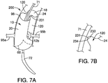
- FIGS. 7A-7B an alternative system 200 for maintaining perfusion of branch vessels is shown and described.
- the system 200 is similar to the system 100 of FIGS. 6A-6B , with a main exception that the graft 20 is secured to itself to form one or more temporary channels 120, as opposed to being secured to the delivery system 70 in the example of FIGS. 6A-6B .
- the system 200 comprises at least one suture 231 that is secured to the graft 20 in a manner that forms the shape of the temporary channel 120.
- the suture 231 may be secured near the distal end 24 of the graft 20 between spaced-apart first and second locations 233 and 234, as depicted in FIG. 7B .
- the dimensions of the suture 231 and its placement relative to locations 233 and 234 produces a tension that maintains the temporary channel 120 until the suture 231 is released.
- multiple sutures 231 may be longitudinally spaced apart between the distal end 24 of the graft 20 and the fenestration 12b, thereby maintaining the temporary channel 120 for a desired longitudinal distance between these locations.
- the temporary channel 120 may comprise a generally "U"-shaped channel external to the graft 20, as shown in FIGS. 7A-7B .
- the suture 231 may extend across the lumen 18 of the prosthesis 10, e.g., sewn to distal ends of the graft 20 at two locations spaced apart about 180 degrees. Such a suture across the lumen 18 may hold opposing sides of the graft 20 at a tension that maintains two temporary channels 120 in place, in the manner shown in FIG. 7A , until the suture is released.
- flow may advantageously be maintained to the coronary arteries during the endovascular procedure, even though the branch vessel prostheses 92a and 92b have not yet been set in place.
- the temporary channel 120 may be withdrawn by removal of the suture 231.
- the delivery system 70 may comprise a balloon, and radially outward expansion of the balloon against the suture 231 may cause breakage of the suture 231, thereby allowing the associated portion of the graft 20 to self-expand without restraint into full engagement with the ascending aorta 98, as shown in FIG. 6C .
- the suture 231 may comprise a biodegradable material and may dissolve after a predetermined period of time, thereby allowing the associated portion of the graft 20 to self-expand without restraint into full engagement with the ascending aorta 98.
- a trigger wire may be used to remove the suture 231, in a manner similar to that shown in FIGS. 6A-6B above. In any of these techniques, flow is advantageously maintained to the coronary arteries in the interim period required to ensure placement of the branch vessel prostheses 92a and 92b.
- the branch vessel prostheses 92a and 92b may be deployed at a later time in a subsequent procedure.
- one or more sutures 231 may maintain the temporary channel 120 to allow sufficient retrograde flow into the coronary arteries 95a and 95b to help sustain the patient while awaiting implantation of the branch prostheses 92a and 92b.
- the system 300 comprises at least one sheath 310 having a proximal end 314, and a distal end (not shown) extending outside of the patient's body. At least one aperture 312 is formed between the proximal and distal ends of the sheath 310.
- the proximal end 314 of the sheath 310 may be advanced into one of the patient's coronary arteries, as depicted in FIG. 8 .
- the sheath 310 may be delivered via any suitable vessel, including but not limited to the brachiocephalic artery.
- the aperture 312 of the sheath 310 is disposed distally beyond the distal end 24 of the graft 20, as the prosthesis 10 is being implanted. At least a portion of the sheath 310 is disposed adjacent to an exterior surface of the graft 20 while the prosthesis 10 is being implanted, and before the branch vessel prostheses 95a and 95b are introduced into their respective coronary arteries. In this manner, blood may flow through the valve 60, through the graft 20, and into the aperture 312, and then flow in a retrograde manner through the sheath 310 and into the coronary artery.
- flow may advantageously be maintained to the coronary arteries during the endovascular procedure, even though the branch vessel prostheses 92a and 92b have not yet been set in place.
- the sheath 310 may be withdrawn from the patient.
- the system 400 comprises at least one external support 410.
- the external support 410 is in the form of a stent framework 411 having proximal and distal ends 412 and 414, respectively.
- the stent framework 411 is disposed adjacent to the outer surface of the graft 20 in a manner such that it forms the shape of the temporary channel 120.
- the distal end 414 of the stent framework 411 may be disposed near the distal end 24 of the graft 20
- the proximal end 412 of the stent framework 411 may be disposed a short distance distal to the fenestration 12b, as depicted in FIG. 9 .
- the external support 410 may be deployed in conjunction with, or before, the partial deployment of the graft 20 as shown in FIG. 9 .
- the external support 410 is disposed adjacent to an exterior surface of the graft 20 while the prosthesis 10 is being implanted, and before the branch vessel prostheses 95a and 95b are introduced into their respective coronary arteries. Accordingly, blood may flow through the valve 60, through the graft 20, and then flow in a retrograde manner through the support 410 and into the coronary artery.
- flow may advantageously be maintained to the coronary arteries during the endovascular procedure, even though the branch vessel prostheses 92a and 92b have not yet been set in place.
- the support 410 may be withdrawn from the patient.
- the support 410 may be removed using a suitable technique such as pulling on a drawstring-like element to induce contraction of the support 410 to a smaller diameter and subsequent capture by a removal sheath.
- the distal end 414 of the support 410 may extend distally beyond the graft 20 such that the distal end 414 remains secured to the delivery device 70 throughout the procedure at a location distal to the graft 20, and then distal removal of the delivery device 70 (after placement of the branch vessel prostheses 92a and 92b) achieves a corresponding distal removal of the support 410.
- the branch vessel prostheses 92a and 92b may be deployed at a later time in a subsequent procedure.
- the support 410 may maintain a temporary channel to allow sufficient retrograde flow into the coronary arteries 95a and 95b to help sustain the patient's health.
- the prosthesis 10 alternatively may be deployed in other parts of a patient's arterial or venous system, or any suitable duct, passageway or vessel, and the various systems 100, 200, 300 and 400 may maintain flow into branch vessels other than the coronary arteries depending on use of the prosthesis 10. While various embodiments of the invention have been described, the invention is not to be restricted except in light of the attached claims.
Description
- The present invention relates to an endoluminal prosthesis system and more particularly to a system for maintaining perfusion of branch vessels during an endovascular procedure.
- The aortic valve functions as a one-way valve between the heart and the rest of the body. Blood is pumped from the left ventricle of the heart, through the aortic valve, and into the aorta, which in turn supplies blood to the body. Between heart contractions the aortic valve closes, preventing blood from flowing backwards into the heart.
- Damage to the aortic valve can occur from a congenital defect, the natural aging process, and from infection or scarring. Over time, calcium may build up around the aortic valve causing the valve not to open and close properly. Certain types of damage may cause the valve to "leak," resulting in "aortic insufficiency" or "aortic regurgitation." Aortic regurgitation causes extra workload for the heart, and can ultimately result in weakening of the heart muscle and eventual heart failure.
- After the aortic valve becomes sufficiently damaged, the valve may need to be replaced to prevent heart failure and death. One approach involves an invasive open procedure. However, patients undergoing such procedure are subjected to a heart-lung bypass, induced cardiac arrest, and extensive trauma to the valve and ascending aorta, and therefore morbidity and mortality rates are relatively high.
- A more recent approach involves endovascularly introducing an aortic valve replacement. However, current endovascular approaches do not allow for sufficient repair of both the aortic valve and the ascending aorta, due to the complex anatomy in this region including the valvular sinus and the coronary arteries. Moreover, attempts to endovascularly repair the aortic valve and the ascending aorta may encompass risks of temporary blocking flow to the coronary arteries during the procedure, which can cause significant complications for a patient.
-
WO 2010/113138 discloses a stent graft fenestration. - The present invention seeks to provide an improved endoluminal prosthesis. According to an aspect of the present invention, there is provided an endoluminal prosthesis system as specified in claim 1.
- A valve replacement may be disposed between the proximal and distal ends of the graft. The removable channel may comprise a "U"-shape.
- In embodiments, the removable channel comprises a sheath having an aperture. The aperture is disposed distal to the distal end of the graft in the partially deployed state, and a portion of the sheath is disposed adjacent to the outer surface of the graft in the partially deployed state. In a further alternative, the removable channel may comprise a removable stent framework disposed exterior to the graft.
- In an embodiment, a shape of the removable channel may be maintained by securement of a first portion of the graft to a second portion of the graft, for example, using at least one suture.
- In an embodiment, the shape of the removable channel may be maintained by securing a wire extending along the delivery system to a coupling member of the graft.
- Other systems, features and advantages of embodiments of the invention will be, or will become, apparent to one with skill in the art upon examination of the following Figures and detailed description. It is intended that all such additional systems, features and advantages be within the scope of the invention, and be encompassed by the following claims.
- Embodiments of the present invention are described with reference to the accompanying drawings, in which:
-
FIG. 1 is a side view of an endoluminal prosthesis comprising a valve replacement; -
FIGS. 2A-2B are, respectively, top and bottom views of the endoluminal prosthesis ofFIG. 1 ; -
FIGS. 3-4 are side views of an exemplary delivery system that may be used to deliver the endoluminal prosthesis ofFIG. 1 ; -
FIG. 5 is a schematic view illustrating deployment of the endoluminal prosthesis ofFIG. 1 in a patient's anatomy; -
FIGS. 6A-6C are, respectively, a perspective view of an embodiment of a temporary channel when a graft is in a partially deployed state, an enlarged view of a segment ofFIG. 6A , and an illustration of the graft in a fully deployed state without the temporary channel; -
FIGS. 7A-7B are, respectively, a perspective view of an alternative embodiment of a temporary channel, and an enlarged view of a segment ofFIG. 7A ; -
FIG. 8 is a perspective view of an embodiment of a temporary channel; and -
FIG. 9 is a perspective view of an embodiment of a temporary channel. - The components in the Figures are not necessarily to scale, emphasis instead being placed upon illustrating the principles of embodiments of the invention.
- In the present application, the term "proximal" refers to a direction that is generally closest to the heart during a medical procedure, while the term "distal" refers to a direction that is furthest from the heart during a medical procedure.
- Referring to
FIGS. 1 to 5 , anendoluminal prosthesis 10 is shown and described. Theprosthesis 10 comprises agraft 20 having a tubular body comprising proximal anddistal ends lumen 18 extending therebetween. - The
prosthesis 10 comprises avalve 60 disposed between theproximal end 22 and thedistal end 24 of thegraft 20. In one example, thevalve 60 can be coupled to thegraft 20 with sutures. - In one non-limiting example, the
valve 60 may comprise an aortic valve designed to replace the function of the recipient's native damaged or poorly performing aortic valve. In other examples, theprosthesis 10 may be deployed in other arterial locations, i.e., other than the aortic annulus and ascending aorta, or alternatively may be deployed in a patient's venous system, or any suitable duct, passageway or vessel. - In the non-limiting example of an aortic valve, the
valve 60 may be located at theproximal end 22 of thegraft 20, closest to the heart. Thevalve 60 preferably includes one ormore leaflets 62, as shown inFIGS. 2A-2B . In this non-limiting example, thevalve 60 includes threeleaflets 62, though only two leaflets may be used in a "bicuspid" arrangement. The leaflets are arranged in the prosthesis such that the leaflets mimic a naturally occurring aortic valve. Thevalve 60 "opens" to allow blood flow when the pressure on the proximal side of thevalve 60 is greater than pressure on the distal side of the artificial valve. Thus, thevalve 60 regulates the unidirectional flow of fluid from the heart into the aorta. - The leaflets of the
valve 60 can be fabricated from any at least substantially biocompatible material including such materials as polyester fabrics, polytetrafluoroethylene (PTFE), expanded PTFE, and other synthetic materials known to those of skill in the art. Preferably, the leaflets are fabricated from naturally occurring biomaterials. The leaflets can include a derived collagen material, such as an extracellular matrix. The extracellular matrix can be small intestinal submucosa, stomach submucosa, pericardium, liver basement membrane, urinary bladder submucosa, tissue mucosa, dura mater, or the like. - The
prosthesis 10 further comprises at least one stent coupled to thegraft 20 that has a contracted delivery state and further has an expanded state for maintaining patency within a portion of the graft. In the exemplary embodiment depicted inFIGS. 1 and5 , fiveexemplary stents 16a-16e are provided. The stents 16 may be placed on the outer surface and/or inner surface of thegraft 20. The exemplary stents 16 of theprosthesis 10 may comprise zig-zag stents or another suitable structure, and may be either self-expanding or balloon expandable. - In the embodiment of
FIG. 1 , afirst stent 16a is located at the proximal end of thegraft 20. In use, thefirst stent 16a overlaps with anaortic annulus 97, as shown inFIG. 5 . Thefirst stent 16a may comprise a radial force configured to facilitate fixation within theaortic annulus 97 and prevent migration of theproximal end 22 of thegraft 20. One ormore barbs 25 may be coupled to thefirst stent 16a to reduce migration of theprosthesis 10. - In the example of
FIG. 1 , theendoluminal prosthesis 10 comprises second and third z-stents graft 20 such that the distal apices of thesecond stent 16b are aligned with the proximal apices of thethird stent 16c. Thefifth stent 16e may be configured to engage a healthy portion of a patient's ascendingaorta 98, as depicted in the deployed state ofFIG. 5 . - The
endoluminal prosthesis 10 further comprises at least one fenestration 12 disposed in asidewall 74 of thegraft 20. The one or more fenestrations 12 may be positioned between a proximal apex of thesecond stent 16b and a distal apex of thethird stent 16c. In the embodiment ofFIGS. 1-5 , first andsecond fenestrations sidewall 74 at locations distal to thevalve 60, as seen in the top view ofFIG. 2A . - The first and
second fenestrations U.S. Patent Application Publication Number 2012/0046728 . - Accordingly, at least one of the
fenestrations FIG. 1 , the first andsecond fenestrations graft 20 at locations between about 90 and about 270 degrees apart, though the positioning may be greater or less. In the deployed state, a firstbranch vessel prosthesis 92a may extend between thefirst fenestration 12a and a firstcoronary artery 95a in a deployed state, and a secondbranch vessel prosthesis 92b may extend between thesecond fenestration 12b and a secondcoronary artery 95b, when theprosthesis 10 is used to repair an aortic valve, as shown inFIG. 5 . - In the examples of
FIGS. 1 to 5 , the deployment of theprosthesis 10 into the state shown inFIG. 5 may be achieved in different manners. In one example, the deployment may be made using a transapical or transeptal approach, in which case theprosthesis 10 may be secured to anexemplary delivery system 70 as shown inFIG. 3 . In the transapical or transeptal approach, anatraumatic tip 72 of the delivery system is advanced in an antegrade fashion, i.e., in a direction from theaortic annulus 97 towards the ascendingaorta 98. - In another example, the deployment may be made using a femoral, carotid, subclavian or axiliary approach, in which case the
prosthesis 10 may be secured to theexemplary delivery system 70 as shown inFIG. 4 . In this approach, theatraumatic tip 72 of thedelivery system 70 is advanced in a retrograde fashion, i.e., in a direction from the ascendingaorta 98 towards theaortic annulus 97. In either delivery approach, as shown inFIGS. 3-4 , thegraft 20 may comprise one ormore regions 73 that are radially restrained. - Access to the
branch vessels branch vessel 95a, a distal portion of thebranch vessel prosthesis 92a may be deployed within thebranch vessel 95a via balloon expansion or self-expansion into engagement with thebranch vessel 95a. Then, a proximal end of thebranch vessel prosthesis 92a, remaining within the interior surface of theprosthesis 10, may be flared in order to provide a proper seal between thefenestration 12a and thebranch vessel 95a. The secondbranch vessel prosthesis 92b may be coupled between theprosthesis 10 and thesecond branch vessel 95b in a similar manner. - Further, the
prosthesis 10 may be provided as part of a preloaded system that includes aguide wire 75. In this example, afirst end segment 76 of theguide wire 75 may enter thelumen 18 through a proximal or distal end of theprosthesis 10, depending on the delivery orientation of the prosthesis shown inFIG. 3 as compared toFIG. 4 . Thefirst end segment 76 exits thegraft 20 through thefirst fenestration 12a. An intermediate segment of theguide wire 75 may extend external of thegraft 20 and reenter thelumen 18 of theprosthesis 10 through thesecond fenestration 12b. Asecond end segment 77 of theguide wire 75 may extend distally within thelumen 18 and may extend distally to the distal end of thedelivery device 70. Thefirst end segment 76 of theguide wire 75 may enable introduction of thefirst branch prosthesis 92a into thefirst fenestration 12a to couple theprosthesis 10 to the right coronary artery, and thesecond end segment 77 of theguide wire 75 may enable introduction of thesecond branch prosthesis 92b into thesecond fenestration 12b to couple the prosthesis to the left coronary artery. - Further details of such a preloaded wire, and how it may facilitate deployment of stent-grafts into branch vessels, are described in further detail in
U.S. Utility Patent Application Serial No. 13/718,915, filed December 18, 2012 prosthesis 10. - In the deployed state, the first
branch vessel prosthesis 92a extends between thefirst fenestration 12a and the firstcoronary artery 95a, and the secondbranch vessel prosthesis 92b extends between thesecond fenestration 12b and the secondcoronary artery 95b, as depicted inFIG. 5 . Advantageously, if the first andsecond fenestrations coronary arteries fenestrations branch vessel prostheses - The
branch vessel prostheses branch vessel prostheses branch vessel prostheses - Referring now to
FIGS. 6A-6C , a first embodiment of asystem 100 for maintaining perfusion of branch vessels is shown and described. Theprosthesis 10 and thedelivery system 70, described inFIGS. 1 to 5 above, may be used in conjunction with thesystem 100 ofFIGS. 6A-6C . It should be noted that in the embodiment ofFIGS. 6A-6C , as well as the embodiments ofFIGS. 7 to 9 below, thestents 16a-16e coupled to theprosthesis 10 have been omitted for illustrative purposes to show further features associated withFIGS. 6 to 9 . - In the embodiment of
FIGS. 6A-6C , thesystem 100 comprises at least onetemporary channel 120, which is formed external to thegraft 20. In the example ofFIGS. 6A-6C , twotemporary channels 120 are shown, one being aligned with thefenestration 12a and the firstcoronary artery 95a, and the other being aligned with thefenestration 12b and the secondcoronary artery 95b, as shown inFIG. 6A . - Each
temporary channel 120 is disposed external to the outer surface of thegraft 20 when thegraft 20 is in a partially deployed state, i.e., other than the fully deployed state ofFIG. 6C . Thetemporary channel 120 begins at one of the proximal anddistal ends graft 20, and extends along only a portion of a longitudinal length of thegraft 20. In the example ofFIGS. 6 to 9 , thetemporary channel 120 begins at thedistal end 24 of thegraft 20, and is disposed at a location between thedistal end 24 of thegraft 20 and one of the fenestration 12. Thetemporary channel 120 is removed when thegraft 20 is in a fully deployed state as shown inFIG. 6C . - The
temporary channels 120 may be formed by coupling a portion of thegraft 20 to a portion of thedelivery system 70. For example, acoupling member 131 in the form of a loop may be secured to thedistal end 24 of thegraft 20, and awire 132 may be releasably coupled to thecoupling member 131, e.g., disposed through the loop. In one example, thewire 132 may extend along a full length of thedelivery system 70, within acatheter 71, and may exit thecatheter 71 through afirst aperture 79a, then engage thecoupling member 131, and then enter back into thecatheter 71 through asecond aperture 79b that is disposed proximal to thefirst aperture 79a, as depicted inFIG. 6B . By holding a portion of thegraft 20 to thedelivery system 70, via thecoupling member 131, thetemporary channel 120 is formed and may comprise a generally "U"-shaped channel external to thegraft 20, as shown inFIG. 6A . - In use, the
prosthesis 10 is generally delivered and at least partially deployed into the state shown inFIG. 6A , as described above with respect toFIG. 5 . Prior to coupling thebranch vessel prostheses respective fenestrations coronary arteries temporary channels 120 provide perfusion pathways for fluid flow into thecoronary arteries valve 60 and thegraft 20, and then flow in a retrograde manner into thetemporary channels 120 and into thecoronary arteries branch vessel prostheses - When a physician is ready to introduce or deploy the
branch vessel prostheses temporary channels 120 may be removed. In the example ofFIGS. 6A-6B , thewire 132 may be withdrawn distally beyond thecoupling member 131, thereby allowing the associated portion of thegraft 20 to self-expand without restraint into full engagement with the ascendingaorta 98, as shown inFIG. 6C . Final placement of thebranch vessel prostheses coronary arteries - Alternatively, the physician may fully deploy the
branch vessel prostheses coronary arteries temporary channels 120. If thesystem 100 comprises a preloaded delivery system as described above, then it may be easier to deploy thebranch vessel prostheses temporary channel 120 occupies a portion of the ascendingaorta 98. - Referring now to
FIGS. 7A-7B , analternative system 200 for maintaining perfusion of branch vessels is shown and described. Thesystem 200 is similar to thesystem 100 ofFIGS. 6A-6B , with a main exception that thegraft 20 is secured to itself to form one or moretemporary channels 120, as opposed to being secured to thedelivery system 70 in the example ofFIGS. 6A-6B . - In one non-limiting example, the
system 200 comprises at least onesuture 231 that is secured to thegraft 20 in a manner that forms the shape of thetemporary channel 120. For example, thesuture 231 may be secured near thedistal end 24 of thegraft 20 between spaced-apart first andsecond locations FIG. 7B . The dimensions of thesuture 231 and its placement relative tolocations temporary channel 120 until thesuture 231 is released. In one embodiment,multiple sutures 231 may be longitudinally spaced apart between thedistal end 24 of thegraft 20 and thefenestration 12b, thereby maintaining thetemporary channel 120 for a desired longitudinal distance between these locations. Thetemporary channel 120 may comprise a generally "U"-shaped channel external to thegraft 20, as shown inFIGS. 7A-7B . - As an alternative placement, the
suture 231 may extend across thelumen 18 of theprosthesis 10, e.g., sewn to distal ends of thegraft 20 at two locations spaced apart about 180 degrees. Such a suture across thelumen 18 may hold opposing sides of thegraft 20 at a tension that maintains twotemporary channels 120 in place, in the manner shown inFIG. 7A , until the suture is released. - As with the prior embodiment of
FIGS. 6A-6C , flow may advantageously be maintained to the coronary arteries during the endovascular procedure, even though thebranch vessel prostheses branch vessel prostheses temporary channel 120 may be withdrawn by removal of thesuture 231. In one embodiment, thedelivery system 70 may comprise a balloon, and radially outward expansion of the balloon against thesuture 231 may cause breakage of thesuture 231, thereby allowing the associated portion of thegraft 20 to self-expand without restraint into full engagement with the ascendingaorta 98, as shown inFIG. 6C . Alternatively, thesuture 231 may comprise a biodegradable material and may dissolve after a predetermined period of time, thereby allowing the associated portion of thegraft 20 to self-expand without restraint into full engagement with the ascendingaorta 98. As a further alternative, a trigger wire may be used to remove thesuture 231, in a manner similar to that shown inFIGS. 6A-6B above. In any of these techniques, flow is advantageously maintained to the coronary arteries in the interim period required to ensure placement of thebranch vessel prostheses - Moreover, in the embodiment of
FIGS. 7A-7B , in the event that thebranch vessel prostheses coronary arteries branch vessel prostheses more sutures 231 may maintain thetemporary channel 120 to allow sufficient retrograde flow into thecoronary arteries branch prostheses - Referring now to
FIG. 8 , analternative system 300 for maintaining perfusion of branch vessels is shown and described. Thesystem 300 comprises at least onesheath 310 having aproximal end 314, and a distal end (not shown) extending outside of the patient's body. At least oneaperture 312 is formed between the proximal and distal ends of thesheath 310. Theproximal end 314 of thesheath 310 may be advanced into one of the patient's coronary arteries, as depicted inFIG. 8 . Thesheath 310 may be delivered via any suitable vessel, including but not limited to the brachiocephalic artery. - The
aperture 312 of thesheath 310 is disposed distally beyond thedistal end 24 of thegraft 20, as theprosthesis 10 is being implanted. At least a portion of thesheath 310 is disposed adjacent to an exterior surface of thegraft 20 while theprosthesis 10 is being implanted, and before thebranch vessel prostheses valve 60, through thegraft 20, and into theaperture 312, and then flow in a retrograde manner through thesheath 310 and into the coronary artery. - As with the prior embodiments of
FIGS. 6-7 , flow may advantageously be maintained to the coronary arteries during the endovascular procedure, even though thebranch vessel prostheses branch vessel prostheses branch vessel prostheses sheath 310 may be withdrawn from the patient. - Referring now to
FIG. 9 , analternative system 400 for maintaining perfusion of branch vessels is shown and described. Thesystem 400 comprises at least oneexternal support 410. In this embodiment, theexternal support 410 is in the form of astent framework 411 having proximal anddistal ends stent framework 411 is disposed adjacent to the outer surface of thegraft 20 in a manner such that it forms the shape of thetemporary channel 120. For example, thedistal end 414 of thestent framework 411 may be disposed near thedistal end 24 of thegraft 20, and theproximal end 412 of thestent framework 411 may be disposed a short distance distal to thefenestration 12b, as depicted inFIG. 9 . Theexternal support 410 may be deployed in conjunction with, or before, the partial deployment of thegraft 20 as shown inFIG. 9 . - In this manner, at least a portion of the
external support 410 is disposed adjacent to an exterior surface of thegraft 20 while theprosthesis 10 is being implanted, and before thebranch vessel prostheses valve 60, through thegraft 20, and then flow in a retrograde manner through thesupport 410 and into the coronary artery. - As with the prior embodiments of
FIGS. 6 to 8 , flow may advantageously be maintained to the coronary arteries during the endovascular procedure, even though thebranch vessel prostheses branch vessel prostheses branch vessel prostheses support 410 may be withdrawn from the patient. - The
support 410 may be removed using a suitable technique such as pulling on a drawstring-like element to induce contraction of thesupport 410 to a smaller diameter and subsequent capture by a removal sheath. Alternatively, thedistal end 414 of thesupport 410 may extend distally beyond thegraft 20 such that thedistal end 414 remains secured to thedelivery device 70 throughout the procedure at a location distal to thegraft 20, and then distal removal of the delivery device 70 (after placement of thebranch vessel prostheses support 410. - In the embodiment of
FIG. 9 , as with the embodiment ofFIGS. 7A-7B above, in the event that thebranch vessel prostheses coronary arteries branch vessel prostheses support 410 may maintain a temporary channel to allow sufficient retrograde flow into thecoronary arteries - As noted above, while one exemplary use of the
prosthesis 10 has been shown with regard to the aortic annulus and ascending aorta for maintaining flow into the coronary arteries, theprosthesis 10 alternatively may be deployed in other parts of a patient's arterial or venous system, or any suitable duct, passageway or vessel, and thevarious systems prosthesis 10. While various embodiments of the invention have been described, the invention is not to be restricted except in light of the attached claims. - Moreover, the advantages described herein are not necessarily the only advantages of the invention and it is not necessarily expected that every embodiment of the invention will achieve all of the advantages described.
- All optional and preferred features and modifications of the described embodiments and dependent claims are usable in all aspects of the invention taught herein. Furthermore, the individual features of the dependent claims, as well as all optional and preferred features and modifications of the described embodiments are combinable and interchangeable with one another.
Claims (12)
- An endoluminal prosthesis system (100, 200, 300, 400) comprising an endoluminal prosthesis (10), wherein said prosthesis (10) comprises:a graft (20) having a tubular body comprising proximal and distal ends (22, 24), and inner and outer surfaces, wherein said graft (20) is adapted to have partially and fully deployed states, and wherein said graft is adapted to form a temporary channel (120, 310, 410) disposed external to the outer surface of the graft in the partially deployed state, the temporary channel beginning at the distal end (24) of the graft, extending along only a portion of a longitudinal length of the graft and terminating before the proximal end (22) of the graft, wherein the temporary channel is adapted to be removed when the graft is in the fully deployed state; andat least one fenestration (12) disposed in a sidewall of the graft (20) between the proximal and distal ends (22, 24) of the graft, wherein the proximal end of the temporary channel is aligned with the fenestration.
- A system (100, 200) as claimed in claim 1, wherein the temporary channel (120) comprises a "U"-shape.
- A system (100, 200, 300, 400) as claimed in claim 1 or 2, comprising a valve replacement (60) disposed between the proximal and distal ends (22, 24) of the graft (20).
- A system (200) as claimed in claim 1, 2 or 3, wherein the shape of the temporary channel (120) is maintained by securement of a first portion of the graft (20) to a second portion of the graft.
- A system (200) as claimed in claim 4, wherein the first portion of the graft (20) is secured to the second portion of the graft using at least one suture (231).
- A system (200) as claimed in claim 5, wherein the suture comprises a biodegradable material, and the temporary channel (120) is adapted to be removed upon degradation of the suture (231).
- A system (200) as claimed in claim 5, wherein the temporary channel (120) is adapted to be removed by breaking the suture (231) using an external force
- A system (300) as claimed in any preceding claim, wherein the temporary channel (120) comprises a sheath (310) having an aperture (312), wherein the aperture is disposed distal to the distal end of the graft (20) in the partially deployed state, and a portion of the sheath is disposed adjacent to the outer surface of the graft in the partially deployed state.
- A system (400) as claimed in any preceding claim, wherein the temporary channel (120) comprises a removable stent framework (411) adapted to be disposed exterior to the graft (20) in the partially deployed state.
- A system (100, 200, 300, 400) as claimed in any preceding claim, comprising a valve replacement (60) disposed within at least a portion of the graft (20).
- A system (100) as claimed in any of claims 1 to 3 or 10 comprising a delivery system (70), wherein the shape of the temporary channel (120) is maintained by securement of a portion of the graft (20) to the delivery system.
- A system as claimed in claim 11, comprising a coupling member (131) secured to the graft (20), and a wire (132) extending along the delivery system (70), wherein the removable channel (120) is maintained when the wire is coupled to the coupling member of the graft, and wherein the temporary channel is removed when the wire is released from engagement with the graft.
Applications Claiming Priority (1)
| Application Number | Priority Date | Filing Date | Title |
|---|---|---|---|
| US13/793,695 US9808364B2 (en) | 2013-03-11 | 2013-03-11 | Systems and methods for maintaining perfusion of branch vessels |
Publications (2)
| Publication Number | Publication Date |
|---|---|
| EP2777608A1 EP2777608A1 (en) | 2014-09-17 |
| EP2777608B1 true EP2777608B1 (en) | 2021-12-29 |
Family
ID=50238323
Family Applications (1)
| Application Number | Title | Priority Date | Filing Date |
|---|---|---|---|
| EP14275047.0A Active EP2777608B1 (en) | 2013-03-11 | 2014-03-10 | Endoluminal prosthesis system |
Country Status (2)
| Country | Link |
|---|---|
| US (1) | US9808364B2 (en) |
| EP (1) | EP2777608B1 (en) |
Cited By (10)
| Publication number | Priority date | Publication date | Assignee | Title |
|---|---|---|---|---|
| US11389294B2 (en) | 2012-05-30 | 2022-07-19 | Neovasc Tiara Inc. | Methods and apparatus for loading a prosthesis onto a delivery system |
| US11389291B2 (en) | 2013-04-04 | 2022-07-19 | Neovase Tiara Inc. | Methods and apparatus for delivering a prosthetic valve to a beating heart |
| US11413139B2 (en) | 2011-11-23 | 2022-08-16 | Neovasc Tiara Inc. | Sequentially deployed transcatheter mitral valve prosthesis |
| US11419720B2 (en) | 2010-05-05 | 2022-08-23 | Neovasc Tiara Inc. | Transcatheter mitral valve prosthesis |
| US11464631B2 (en) | 2016-11-21 | 2022-10-11 | Neovasc Tiara Inc. | Methods and systems for rapid retraction of a transcatheter heart valve delivery system |
| US11491006B2 (en) | 2019-04-10 | 2022-11-08 | Neovasc Tiara Inc. | Prosthetic valve with natural blood flow |
| US11497602B2 (en) | 2012-02-14 | 2022-11-15 | Neovasc Tiara Inc. | Methods and apparatus for engaging a valve prosthesis with tissue |
| US11602429B2 (en) | 2019-04-01 | 2023-03-14 | Neovasc Tiara Inc. | Controllably deployable prosthetic valve |
| US11737872B2 (en) | 2018-11-08 | 2023-08-29 | Neovasc Tiara Inc. | Ventricular deployment of a transcatheter mitral valve prosthesis |
| US11793640B2 (en) | 2017-08-25 | 2023-10-24 | Neovasc Tiara Inc. | Sequentially deployed transcatheter mitral valve prosthesis |
Families Citing this family (9)
| Publication number | Priority date | Publication date | Assignee | Title |
|---|---|---|---|---|
| US9101455B2 (en) | 2010-08-13 | 2015-08-11 | Cook Medical Technologies Llc | Preloaded wire for endoluminal device |
| CA2747610C (en) | 2010-08-13 | 2014-09-16 | Cook Medical Technologies Llc | Precannulated fenestration |
| US10524944B1 (en) * | 2014-01-29 | 2020-01-07 | W. L. Gore & Associates, Inc. | Delivery systems and methods of endoluminal delivery of branched vascular endoprosthetic devices |
| US10610393B2 (en) | 2016-03-24 | 2020-04-07 | Cook Medical Technologies Llc | Wire retention and release mechanisms |
| US10500079B2 (en) | 2016-10-27 | 2019-12-10 | Cook Medical Technologies Llc | Preloaded branch wire loop constraint |
| US10874501B2 (en) | 2016-12-28 | 2020-12-29 | Cook Medical Technologies Llc | Low profile stent graft having a check valve |
| IT201700031905A1 (en) * | 2017-03-23 | 2018-09-23 | Enrico Riccardo Ferrari | Aortic endoprosthesis. |
| WO2019205599A1 (en) * | 2018-04-25 | 2019-10-31 | 上海长海医院 | Ascending aortic stent graft |
| CN112006811B (en) * | 2019-05-28 | 2024-02-06 | 上海创心医学科技有限公司 | Vascular reconstruction device |
Family Cites Families (22)
| Publication number | Priority date | Publication date | Assignee | Title |
|---|---|---|---|---|
| US5387235A (en) * | 1991-10-25 | 1995-02-07 | Cook Incorporated | Expandable transluminal graft prosthesis for repair of aneurysm |
| US5720776A (en) * | 1991-10-25 | 1998-02-24 | Cook Incorporated | Barb and expandable transluminal graft prosthesis for repair of aneurysm |
| US6015429A (en) * | 1994-09-08 | 2000-01-18 | Gore Enterprise Holdings, Inc. | Procedures for introducing stents and stent-grafts |
| WO1996036297A1 (en) * | 1995-05-19 | 1996-11-21 | Kanji Inoue | Transplantation instrument, method of bending same and method of transplanting same |
| US5948017A (en) * | 1997-10-12 | 1999-09-07 | Taheri; Syde A. | Modular graft assembly |
| US6458153B1 (en) * | 1999-12-31 | 2002-10-01 | Abps Venture One, Ltd. | Endoluminal cardiac and venous valve prostheses and methods of manufacture and delivery thereof |
| US6676699B2 (en) * | 2002-04-26 | 2004-01-13 | Medtronic Ave, Inc | Stent graft with integrated valve device and method |
| AU2003258337A1 (en) * | 2002-08-23 | 2004-03-11 | Cook Incorporated | Asymmetric stent graft attachment |
| US7998186B2 (en) * | 2003-10-14 | 2011-08-16 | William A. Cook Australia Pty. Ltd. | Introducer for a side branch device |
| US8043354B2 (en) * | 2004-06-16 | 2011-10-25 | William A. Cook Australia Pty. Ltd. | Thoracic deployment device and stent graft |
| US20070168013A1 (en) * | 2006-01-19 | 2007-07-19 | Myles Douglas | Vascular graft and deployment system |
| US8167930B2 (en) * | 2006-11-07 | 2012-05-01 | William A. Cook Australia Pty. Ltd. | Stent graft for treatment of emergency rupture of a vessel |
| US20090270971A1 (en) * | 2008-04-24 | 2009-10-29 | Medtronic Vascular, Inc. | Prosthesis Fixation Apparatus and Methods |
| DE202009018961U1 (en) * | 2008-07-15 | 2014-11-26 | St. Jude Medical, Inc. | Heart valve prosthesis and arrangement for delivering a heart valve prosthesis |
| GB2464977B (en) * | 2008-10-31 | 2010-11-03 | William Cook Europe As | Introducer for deploying a stent graft in a curved lumen and stent graft therefor |
| AU2009200350B1 (en) * | 2009-02-02 | 2009-07-16 | Cook Incorporated | Preloaded stent graft delivery device |
| US20120041544A1 (en) | 2009-04-02 | 2012-02-16 | The Medical Research, Infrastructure and Health Services Fund of the Tel Aviv Medical Center | Stent graft fenestration |
| US20100268318A1 (en) * | 2009-04-16 | 2010-10-21 | Medtronic Vascular, Inc. | Prosthesis for Antegrade Deployment |
| US8771333B2 (en) * | 2009-06-23 | 2014-07-08 | Cordis Corporation | Stent-graft securement device |
| WO2010150208A2 (en) * | 2009-06-23 | 2010-12-29 | Endospan Ltd. | Vascular prostheses for treating aneurysms |
| CA2748206C (en) | 2010-08-21 | 2015-06-23 | Blayne A. Roeder | Prosthesis having pivoting fenestration |
| US9662196B2 (en) * | 2011-09-27 | 2017-05-30 | Cook Medical Technologies Llc | Endoluminal prosthesis with steerable branch |
-
2013
- 2013-03-11 US US13/793,695 patent/US9808364B2/en active Active
-
2014
- 2014-03-10 EP EP14275047.0A patent/EP2777608B1/en active Active
Cited By (11)
| Publication number | Priority date | Publication date | Assignee | Title |
|---|---|---|---|---|
| US11419720B2 (en) | 2010-05-05 | 2022-08-23 | Neovasc Tiara Inc. | Transcatheter mitral valve prosthesis |
| US11413139B2 (en) | 2011-11-23 | 2022-08-16 | Neovasc Tiara Inc. | Sequentially deployed transcatheter mitral valve prosthesis |
| US11497602B2 (en) | 2012-02-14 | 2022-11-15 | Neovasc Tiara Inc. | Methods and apparatus for engaging a valve prosthesis with tissue |
| US11389294B2 (en) | 2012-05-30 | 2022-07-19 | Neovasc Tiara Inc. | Methods and apparatus for loading a prosthesis onto a delivery system |
| US11617650B2 (en) | 2012-05-30 | 2023-04-04 | Neovasc Tiara Inc. | Methods and apparatus for loading a prosthesis onto a delivery system |
| US11389291B2 (en) | 2013-04-04 | 2022-07-19 | Neovase Tiara Inc. | Methods and apparatus for delivering a prosthetic valve to a beating heart |
| US11464631B2 (en) | 2016-11-21 | 2022-10-11 | Neovasc Tiara Inc. | Methods and systems for rapid retraction of a transcatheter heart valve delivery system |
| US11793640B2 (en) | 2017-08-25 | 2023-10-24 | Neovasc Tiara Inc. | Sequentially deployed transcatheter mitral valve prosthesis |
| US11737872B2 (en) | 2018-11-08 | 2023-08-29 | Neovasc Tiara Inc. | Ventricular deployment of a transcatheter mitral valve prosthesis |
| US11602429B2 (en) | 2019-04-01 | 2023-03-14 | Neovasc Tiara Inc. | Controllably deployable prosthetic valve |
| US11491006B2 (en) | 2019-04-10 | 2022-11-08 | Neovasc Tiara Inc. | Prosthetic valve with natural blood flow |
Also Published As
| Publication number | Publication date |
|---|---|
| US20140257453A1 (en) | 2014-09-11 |
| US9808364B2 (en) | 2017-11-07 |
| EP2777608A1 (en) | 2014-09-17 |
Similar Documents
| Publication | Publication Date | Title |
|---|---|---|
| EP2777608B1 (en) | Endoluminal prosthesis system | |
| US11911270B2 (en) | Stent structures for use with valve replacements | |
| US10842618B2 (en) | Endoluminal prosthesis comprising a valve and an axially extendable segment | |
| EP2478869B1 (en) | Aortic valve prosthesis | |
| EP2491892B1 (en) | Stent graft with valve arrangement and introducer assembly therefor | |
| EP1729685B1 (en) | Endoluminal graft with a prosthetic valve | |
| US9839542B2 (en) | Mobile external coupling for branch vessel connection | |
| EP2606852B1 (en) | Endoluminal prosthesis comprising a valve replacement and at least one fenestration | |
| US8771336B2 (en) | Endoluminal prosthesis comprising a valve replacement and at least one fenestration | |
| EP2985007B1 (en) | Preloaded wire for endoluminal device | |
| EP2745813A1 (en) | Preloaded wire for endoluminal device | |
| US20190069986A1 (en) | Endoluminal prosthesis with an aortic sinus stent assembly |
Legal Events
| Date | Code | Title | Description |
|---|---|---|---|
| 17P | Request for examination filed |
Effective date: 20140310 |
|
| AK | Designated contracting states |
Kind code of ref document: A1 Designated state(s): AL AT BE BG CH CY CZ DE DK EE ES FI FR GB GR HR HU IE IS IT LI LT LU LV MC MK MT NL NO PL PT RO RS SE SI SK SM TR |
|
| AX | Request for extension of the european patent |
Extension state: BA ME |
|
| PUAI | Public reference made under article 153(3) epc to a published international application that has entered the european phase |
Free format text: ORIGINAL CODE: 0009012 |
|
| R17P | Request for examination filed (corrected) |
Effective date: 20150311 |
|
| RBV | Designated contracting states (corrected) |
Designated state(s): AL AT BE BG CH CY CZ DE DK EE ES FI FR GB GR HR HU IE IS IT LI LT LU LV MC MK MT NL NO PL PT RO RS SE SI SK SM TR |
|
| 17Q | First examination report despatched |
Effective date: 20160613 |
|
| STAA | Information on the status of an ep patent application or granted ep patent |
Free format text: STATUS: EXAMINATION IS IN PROGRESS |
|
| STAA | Information on the status of an ep patent application or granted ep patent |
Free format text: STATUS: EXAMINATION IS IN PROGRESS |
|
| GRAP | Despatch of communication of intention to grant a patent |
Free format text: ORIGINAL CODE: EPIDOSNIGR1 |
|
| STAA | Information on the status of an ep patent application or granted ep patent |
Free format text: STATUS: GRANT OF PATENT IS INTENDED |
|
| RIC1 | Information provided on ipc code assigned before grant |
Ipc: A61F 2/844 20130101ALN20210721BHEP Ipc: A61F 2/24 20060101ALN20210721BHEP Ipc: A61F 2/07 20130101AFI20210721BHEP |
|
| INTG | Intention to grant announced |
Effective date: 20210806 |
|
| GRAS | Grant fee paid |
Free format text: ORIGINAL CODE: EPIDOSNIGR3 |
|
| GRAA | (expected) grant |
Free format text: ORIGINAL CODE: 0009210 |
|
| STAA | Information on the status of an ep patent application or granted ep patent |
Free format text: STATUS: THE PATENT HAS BEEN GRANTED |
|
| AK | Designated contracting states |
Kind code of ref document: B1 Designated state(s): AL AT BE BG CH CY CZ DE DK EE ES FI FR GB GR HR HU IE IS IT LI LT LU LV MC MK MT NL NO PL PT RO RS SE SI SK SM TR |
|
| REG | Reference to a national code |
Ref country code: GB Ref legal event code: FG4D |
|
| REG | Reference to a national code |
Ref country code: CH Ref legal event code: EP |
|
| REG | Reference to a national code |
Ref country code: DE Ref legal event code: R096 Ref document number: 602014081899 Country of ref document: DE |
|
| REG | Reference to a national code |
Ref country code: AT Ref legal event code: REF Ref document number: 1458128 Country of ref document: AT Kind code of ref document: T Effective date: 20220115 |
|
| REG | Reference to a national code |
Ref country code: IE Ref legal event code: FG4D |
|
| REG | Reference to a national code |
Ref country code: LT Ref legal event code: MG9D |
|
| PG25 | Lapsed in a contracting state [announced via postgrant information from national office to epo] |
Ref country code: RS Free format text: LAPSE BECAUSE OF FAILURE TO SUBMIT A TRANSLATION OF THE DESCRIPTION OR TO PAY THE FEE WITHIN THE PRESCRIBED TIME-LIMIT Effective date: 20211229 Ref country code: LT Free format text: LAPSE BECAUSE OF FAILURE TO SUBMIT A TRANSLATION OF THE DESCRIPTION OR TO PAY THE FEE WITHIN THE PRESCRIBED TIME-LIMIT Effective date: 20211229 Ref country code: FI Free format text: LAPSE BECAUSE OF FAILURE TO SUBMIT A TRANSLATION OF THE DESCRIPTION OR TO PAY THE FEE WITHIN THE PRESCRIBED TIME-LIMIT Effective date: 20211229 Ref country code: BG Free format text: LAPSE BECAUSE OF FAILURE TO SUBMIT A TRANSLATION OF THE DESCRIPTION OR TO PAY THE FEE WITHIN THE PRESCRIBED TIME-LIMIT Effective date: 20220329 |
|
| REG | Reference to a national code |
Ref country code: NL Ref legal event code: MP Effective date: 20211229 |
|
| REG | Reference to a national code |
Ref country code: AT Ref legal event code: MK05 Ref document number: 1458128 Country of ref document: AT Kind code of ref document: T Effective date: 20211229 |
|
| PG25 | Lapsed in a contracting state [announced via postgrant information from national office to epo] |
Ref country code: SE Free format text: LAPSE BECAUSE OF FAILURE TO SUBMIT A TRANSLATION OF THE DESCRIPTION OR TO PAY THE FEE WITHIN THE PRESCRIBED TIME-LIMIT Effective date: 20211229 Ref country code: NO Free format text: LAPSE BECAUSE OF FAILURE TO SUBMIT A TRANSLATION OF THE DESCRIPTION OR TO PAY THE FEE WITHIN THE PRESCRIBED TIME-LIMIT Effective date: 20220329 Ref country code: LV Free format text: LAPSE BECAUSE OF FAILURE TO SUBMIT A TRANSLATION OF THE DESCRIPTION OR TO PAY THE FEE WITHIN THE PRESCRIBED TIME-LIMIT Effective date: 20211229 Ref country code: HR Free format text: LAPSE BECAUSE OF FAILURE TO SUBMIT A TRANSLATION OF THE DESCRIPTION OR TO PAY THE FEE WITHIN THE PRESCRIBED TIME-LIMIT Effective date: 20211229 Ref country code: GR Free format text: LAPSE BECAUSE OF FAILURE TO SUBMIT A TRANSLATION OF THE DESCRIPTION OR TO PAY THE FEE WITHIN THE PRESCRIBED TIME-LIMIT Effective date: 20220330 |
|
| PG25 | Lapsed in a contracting state [announced via postgrant information from national office to epo] |
Ref country code: NL Free format text: LAPSE BECAUSE OF FAILURE TO SUBMIT A TRANSLATION OF THE DESCRIPTION OR TO PAY THE FEE WITHIN THE PRESCRIBED TIME-LIMIT Effective date: 20211229 |
|
| PG25 | Lapsed in a contracting state [announced via postgrant information from national office to epo] |
Ref country code: SM Free format text: LAPSE BECAUSE OF FAILURE TO SUBMIT A TRANSLATION OF THE DESCRIPTION OR TO PAY THE FEE WITHIN THE PRESCRIBED TIME-LIMIT Effective date: 20211229 Ref country code: SK Free format text: LAPSE BECAUSE OF FAILURE TO SUBMIT A TRANSLATION OF THE DESCRIPTION OR TO PAY THE FEE WITHIN THE PRESCRIBED TIME-LIMIT Effective date: 20211229 Ref country code: RO Free format text: LAPSE BECAUSE OF FAILURE TO SUBMIT A TRANSLATION OF THE DESCRIPTION OR TO PAY THE FEE WITHIN THE PRESCRIBED TIME-LIMIT Effective date: 20211229 Ref country code: PT Free format text: LAPSE BECAUSE OF FAILURE TO SUBMIT A TRANSLATION OF THE DESCRIPTION OR TO PAY THE FEE WITHIN THE PRESCRIBED TIME-LIMIT Effective date: 20220429 Ref country code: ES Free format text: LAPSE BECAUSE OF FAILURE TO SUBMIT A TRANSLATION OF THE DESCRIPTION OR TO PAY THE FEE WITHIN THE PRESCRIBED TIME-LIMIT Effective date: 20211229 Ref country code: EE Free format text: LAPSE BECAUSE OF FAILURE TO SUBMIT A TRANSLATION OF THE DESCRIPTION OR TO PAY THE FEE WITHIN THE PRESCRIBED TIME-LIMIT Effective date: 20211229 Ref country code: CZ Free format text: LAPSE BECAUSE OF FAILURE TO SUBMIT A TRANSLATION OF THE DESCRIPTION OR TO PAY THE FEE WITHIN THE PRESCRIBED TIME-LIMIT Effective date: 20211229 |
|
| PG25 | Lapsed in a contracting state [announced via postgrant information from national office to epo] |
Ref country code: PL Free format text: LAPSE BECAUSE OF FAILURE TO SUBMIT A TRANSLATION OF THE DESCRIPTION OR TO PAY THE FEE WITHIN THE PRESCRIBED TIME-LIMIT Effective date: 20211229 Ref country code: AT Free format text: LAPSE BECAUSE OF FAILURE TO SUBMIT A TRANSLATION OF THE DESCRIPTION OR TO PAY THE FEE WITHIN THE PRESCRIBED TIME-LIMIT Effective date: 20211229 |
|
| PG25 | Lapsed in a contracting state [announced via postgrant information from national office to epo] |
Ref country code: IS Free format text: LAPSE BECAUSE OF FAILURE TO SUBMIT A TRANSLATION OF THE DESCRIPTION OR TO PAY THE FEE WITHIN THE PRESCRIBED TIME-LIMIT Effective date: 20220429 |
|
| REG | Reference to a national code |
Ref country code: DE Ref legal event code: R097 Ref document number: 602014081899 Country of ref document: DE |
|
| PG25 | Lapsed in a contracting state [announced via postgrant information from national office to epo] |
Ref country code: MC Free format text: LAPSE BECAUSE OF FAILURE TO SUBMIT A TRANSLATION OF THE DESCRIPTION OR TO PAY THE FEE WITHIN THE PRESCRIBED TIME-LIMIT Effective date: 20211229 Ref country code: DK Free format text: LAPSE BECAUSE OF FAILURE TO SUBMIT A TRANSLATION OF THE DESCRIPTION OR TO PAY THE FEE WITHIN THE PRESCRIBED TIME-LIMIT Effective date: 20211229 Ref country code: AL Free format text: LAPSE BECAUSE OF FAILURE TO SUBMIT A TRANSLATION OF THE DESCRIPTION OR TO PAY THE FEE WITHIN THE PRESCRIBED TIME-LIMIT Effective date: 20211229 |
|
| REG | Reference to a national code |
Ref country code: CH Ref legal event code: PL |
|
| PLBE | No opposition filed within time limit |
Free format text: ORIGINAL CODE: 0009261 |
|
| STAA | Information on the status of an ep patent application or granted ep patent |
Free format text: STATUS: NO OPPOSITION FILED WITHIN TIME LIMIT |
|
| 26N | No opposition filed |
Effective date: 20220930 |
|
| REG | Reference to a national code |
Ref country code: BE Ref legal event code: MM Effective date: 20220331 |
|
| PG25 | Lapsed in a contracting state [announced via postgrant information from national office to epo] |
Ref country code: LU Free format text: LAPSE BECAUSE OF NON-PAYMENT OF DUE FEES Effective date: 20220310 Ref country code: LI Free format text: LAPSE BECAUSE OF NON-PAYMENT OF DUE FEES Effective date: 20220331 Ref country code: FR Free format text: LAPSE BECAUSE OF NON-PAYMENT OF DUE FEES Effective date: 20220331 Ref country code: CH Free format text: LAPSE BECAUSE OF NON-PAYMENT OF DUE FEES Effective date: 20220331 |
|
| PG25 | Lapsed in a contracting state [announced via postgrant information from national office to epo] |
Ref country code: SI Free format text: LAPSE BECAUSE OF FAILURE TO SUBMIT A TRANSLATION OF THE DESCRIPTION OR TO PAY THE FEE WITHIN THE PRESCRIBED TIME-LIMIT Effective date: 20211229 Ref country code: BE Free format text: LAPSE BECAUSE OF NON-PAYMENT OF DUE FEES Effective date: 20220331 |
|
| PGFP | Annual fee paid to national office [announced via postgrant information from national office to epo] |
Ref country code: IE Payment date: 20230223 Year of fee payment: 10 |
|
| PG25 | Lapsed in a contracting state [announced via postgrant information from national office to epo] |
Ref country code: IT Free format text: LAPSE BECAUSE OF FAILURE TO SUBMIT A TRANSLATION OF THE DESCRIPTION OR TO PAY THE FEE WITHIN THE PRESCRIBED TIME-LIMIT Effective date: 20211229 |
|
| PGFP | Annual fee paid to national office [announced via postgrant information from national office to epo] |
Ref country code: GB Payment date: 20230208 Year of fee payment: 10 Ref country code: DE Payment date: 20230210 Year of fee payment: 10 |
|
| P01 | Opt-out of the competence of the unified patent court (upc) registered |
Effective date: 20230602 |
|
| PG25 | Lapsed in a contracting state [announced via postgrant information from national office to epo] |
Ref country code: HU Free format text: LAPSE BECAUSE OF FAILURE TO SUBMIT A TRANSLATION OF THE DESCRIPTION OR TO PAY THE FEE WITHIN THE PRESCRIBED TIME-LIMIT; INVALID AB INITIO Effective date: 20140310 |
|
| PGFP | Annual fee paid to national office [announced via postgrant information from national office to epo] |
Ref country code: IE Payment date: 20240226 Year of fee payment: 11 |