EP2777598B1 - Container for surgical object and fluid monitoring system - Google Patents
Container for surgical object and fluid monitoring system Download PDFInfo
- Publication number
- EP2777598B1 EP2777598B1 EP14159723.7A EP14159723A EP2777598B1 EP 2777598 B1 EP2777598 B1 EP 2777598B1 EP 14159723 A EP14159723 A EP 14159723A EP 2777598 B1 EP2777598 B1 EP 2777598B1
- Authority
- EP
- European Patent Office
- Prior art keywords
- container
- top member
- port opening
- bag body
- flexible bag
- Prior art date
- Legal status (The legal status is an assumption and is not a legal conclusion. Google has not performed a legal analysis and makes no representation as to the accuracy of the status listed.)
- Active
Links
- 239000012530 fluid Substances 0.000 title claims description 46
- 238000012544 monitoring process Methods 0.000 title claims description 22
- 230000003287 optical effect Effects 0.000 claims description 52
- 238000001514 detection method Methods 0.000 claims description 32
- 239000000463 material Substances 0.000 claims description 17
- 238000010276 construction Methods 0.000 claims description 12
- 238000000034 method Methods 0.000 claims description 11
- 230000008859 change Effects 0.000 claims description 10
- 238000001356 surgical procedure Methods 0.000 claims description 10
- 230000005484 gravity Effects 0.000 claims description 7
- 238000005259 measurement Methods 0.000 claims description 6
- 238000013461 design Methods 0.000 claims description 3
- 230000002401 inhibitory effect Effects 0.000 claims 5
- 238000004891 communication Methods 0.000 description 9
- 238000012545 processing Methods 0.000 description 9
- 239000008280 blood Substances 0.000 description 7
- 210000004369 blood Anatomy 0.000 description 7
- 239000000853 adhesive Substances 0.000 description 6
- 230000001070 adhesive effect Effects 0.000 description 6
- 230000006870 function Effects 0.000 description 3
- 230000008878 coupling Effects 0.000 description 2
- 238000010168 coupling process Methods 0.000 description 2
- 238000005859 coupling reaction Methods 0.000 description 2
- 230000001186 cumulative effect Effects 0.000 description 2
- 230000000670 limiting effect Effects 0.000 description 2
- 230000013011 mating Effects 0.000 description 2
- 230000002829 reductive effect Effects 0.000 description 2
- 230000000284 resting effect Effects 0.000 description 2
- 239000004698 Polyethylene Substances 0.000 description 1
- 238000013459 approach Methods 0.000 description 1
- 239000012611 container material Substances 0.000 description 1
- 230000001419 dependent effect Effects 0.000 description 1
- 238000005516 engineering process Methods 0.000 description 1
- 230000008020 evaporation Effects 0.000 description 1
- 238000001704 evaporation Methods 0.000 description 1
- 239000010408 film Substances 0.000 description 1
- 231100001261 hazardous Toxicity 0.000 description 1
- 239000000383 hazardous chemical Substances 0.000 description 1
- 239000004973 liquid crystal related substance Substances 0.000 description 1
- 238000004806 packaging method and process Methods 0.000 description 1
- 239000004033 plastic Substances 0.000 description 1
- 229920003023 plastic Polymers 0.000 description 1
- -1 polyethylene Polymers 0.000 description 1
- 229920000573 polyethylene Polymers 0.000 description 1
- 239000002861 polymer material Substances 0.000 description 1
- 230000008569 process Effects 0.000 description 1
- 230000001681 protective effect Effects 0.000 description 1
- 230000000717 retained effect Effects 0.000 description 1
- 230000002441 reversible effect Effects 0.000 description 1
- 229920006395 saturated elastomer Polymers 0.000 description 1
- 210000002966 serum Anatomy 0.000 description 1
Images


Classifications
-
- A—HUMAN NECESSITIES
- A61—MEDICAL OR VETERINARY SCIENCE; HYGIENE
- A61B—DIAGNOSIS; SURGERY; IDENTIFICATION
- A61B5/00—Measuring for diagnostic purposes; Identification of persons
- A61B5/02—Detecting, measuring or recording pulse, heart rate, blood pressure or blood flow; Combined pulse/heart-rate/blood pressure determination; Evaluating a cardiovascular condition not otherwise provided for, e.g. using combinations of techniques provided for in this group with electrocardiography or electroauscultation; Heart catheters for measuring blood pressure
- A61B5/02042—Determining blood loss or bleeding, e.g. during a surgical procedure
-
- A—HUMAN NECESSITIES
- A61—MEDICAL OR VETERINARY SCIENCE; HYGIENE
- A61M—DEVICES FOR INTRODUCING MEDIA INTO, OR ONTO, THE BODY; DEVICES FOR TRANSDUCING BODY MEDIA OR FOR TAKING MEDIA FROM THE BODY; DEVICES FOR PRODUCING OR ENDING SLEEP OR STUPOR
- A61M1/00—Suction or pumping devices for medical purposes; Devices for carrying-off, for treatment of, or for carrying-over, body-liquids; Drainage systems
- A61M1/71—Suction drainage systems
- A61M1/77—Suction-irrigation systems
- A61M1/777—Determination of loss or gain of body fluids due to suction-irrigation, e.g. during surgery
-
- B—PERFORMING OPERATIONS; TRANSPORTING
- B65—CONVEYING; PACKING; STORING; HANDLING THIN OR FILAMENTARY MATERIAL
- B65F—GATHERING OR REMOVAL OF DOMESTIC OR LIKE REFUSE
- B65F1/00—Refuse receptacles; Accessories therefor
- B65F1/14—Other constructional features; Accessories
- B65F1/141—Supports, racks, stands, posts or the like for holding refuse receptacles
- B65F1/1415—Supports, racks, stands, posts or the like for holding refuse receptacles for flexible receptables, e.g. bags, sacks
-
- G—PHYSICS
- G01—MEASURING; TESTING
- G01G—WEIGHING
- G01G19/00—Weighing apparatus or methods adapted for special purposes not provided for in the preceding groups
- G01G19/40—Weighing apparatus or methods adapted for special purposes not provided for in the preceding groups with provisions for indicating, recording, or computing price or other quantities dependent on the weight
- G01G19/42—Weighing apparatus or methods adapted for special purposes not provided for in the preceding groups with provisions for indicating, recording, or computing price or other quantities dependent on the weight for counting by weighing
-
- A—HUMAN NECESSITIES
- A61—MEDICAL OR VETERINARY SCIENCE; HYGIENE
- A61B—DIAGNOSIS; SURGERY; IDENTIFICATION
- A61B90/00—Instruments, implements or accessories specially adapted for surgery or diagnosis and not covered by any of the groups A61B1/00 - A61B50/00, e.g. for luxation treatment or for protecting wound edges
- A61B90/08—Accessories or related features not otherwise provided for
- A61B2090/0804—Counting number of instruments used; Instrument detectors
- A61B2090/0805—Counting number of instruments used; Instrument detectors automatically, e.g. by means of magnetic, optical or photoelectric detectors
-
- A—HUMAN NECESSITIES
- A61—MEDICAL OR VETERINARY SCIENCE; HYGIENE
- A61B—DIAGNOSIS; SURGERY; IDENTIFICATION
- A61B2217/00—General characteristics of surgical instruments
- A61B2217/002—Auxiliary appliance
- A61B2217/005—Auxiliary appliance with suction drainage system
-
- A—HUMAN NECESSITIES
- A61—MEDICAL OR VETERINARY SCIENCE; HYGIENE
- A61B—DIAGNOSIS; SURGERY; IDENTIFICATION
- A61B2217/00—General characteristics of surgical instruments
- A61B2217/002—Auxiliary appliance
- A61B2217/007—Auxiliary appliance with irrigation system
-
- B—PERFORMING OPERATIONS; TRANSPORTING
- B62—LAND VEHICLES FOR TRAVELLING OTHERWISE THAN ON RAILS
- B62B—HAND-PROPELLED VEHICLES, e.g. HAND CARTS OR PERAMBULATORS; SLEDGES
- B62B2203/00—Grasping, holding, supporting the objects
- B62B2203/02—Grasping, holding, supporting the objects suspended
-
- B—PERFORMING OPERATIONS; TRANSPORTING
- B62—LAND VEHICLES FOR TRAVELLING OTHERWISE THAN ON RAILS
- B62B—HAND-PROPELLED VEHICLES, e.g. HAND CARTS OR PERAMBULATORS; SLEDGES
- B62B2203/00—Grasping, holding, supporting the objects
- B62B2203/50—Grasping, holding, supporting the objects comprising weighing means
-
- B—PERFORMING OPERATIONS; TRANSPORTING
- B62—LAND VEHICLES FOR TRAVELLING OTHERWISE THAN ON RAILS
- B62B—HAND-PROPELLED VEHICLES, e.g. HAND CARTS OR PERAMBULATORS; SLEDGES
- B62B3/00—Hand carts having more than one axis carrying transport wheels; Steering devices therefor; Equipment therefor
- B62B3/10—Hand carts having more than one axis carrying transport wheels; Steering devices therefor; Equipment therefor characterised by supports specially adapted to objects of definite shape
- B62B3/106—Hand carts having more than one axis carrying transport wheels; Steering devices therefor; Equipment therefor characterised by supports specially adapted to objects of definite shape the objects being bags
-
- B—PERFORMING OPERATIONS; TRANSPORTING
- B65—CONVEYING; PACKING; STORING; HANDLING THIN OR FILAMENTARY MATERIAL
- B65F—GATHERING OR REMOVAL OF DOMESTIC OR LIKE REFUSE
- B65F1/00—Refuse receptacles; Accessories therefor
- B65F1/14—Other constructional features; Accessories
- B65F1/1468—Means for facilitating the transport of the receptacle, e.g. wheels, rolls
- B65F1/1473—Receptacles having wheels
-
- B—PERFORMING OPERATIONS; TRANSPORTING
- B65—CONVEYING; PACKING; STORING; HANDLING THIN OR FILAMENTARY MATERIAL
- B65F—GATHERING OR REMOVAL OF DOMESTIC OR LIKE REFUSE
- B65F1/00—Refuse receptacles; Accessories therefor
- B65F1/14—Other constructional features; Accessories
- B65F1/16—Lids or covers
- B65F1/1607—Lids or covers with filling openings
-
- B—PERFORMING OPERATIONS; TRANSPORTING
- B65—CONVEYING; PACKING; STORING; HANDLING THIN OR FILAMENTARY MATERIAL
- B65F—GATHERING OR REMOVAL OF DOMESTIC OR LIKE REFUSE
- B65F2210/00—Equipment of refuse receptacles
- B65F2210/124—Counting means
-
- B—PERFORMING OPERATIONS; TRANSPORTING
- B65—CONVEYING; PACKING; STORING; HANDLING THIN OR FILAMENTARY MATERIAL
- B65F—GATHERING OR REMOVAL OF DOMESTIC OR LIKE REFUSE
- B65F2210/00—Equipment of refuse receptacles
- B65F2210/168—Sensing means
-
- B—PERFORMING OPERATIONS; TRANSPORTING
- B65—CONVEYING; PACKING; STORING; HANDLING THIN OR FILAMENTARY MATERIAL
- B65F—GATHERING OR REMOVAL OF DOMESTIC OR LIKE REFUSE
- B65F2210/00—Equipment of refuse receptacles
- B65F2210/184—Weighing means
-
- B—PERFORMING OPERATIONS; TRANSPORTING
- B65—CONVEYING; PACKING; STORING; HANDLING THIN OR FILAMENTARY MATERIAL
- B65F—GATHERING OR REMOVAL OF DOMESTIC OR LIKE REFUSE
- B65F2240/00—Types of refuse collected
- B65F2240/145—Medicine
Definitions
- the present disclosure generally relates to surgical object monitoring systems, and more particularly to a container for use with surgical object (e.g., a surgical sponge) monitoring system that can monitor and track surgical objects and the fluid of a patient during a surgical procedure.
- surgical object e.g., a surgical sponge
- Surgical object monitoring systems have attempted to keep track of surgical objects with varying degrees of success. Some monitoring systems have relied almost entirely on manual counting of objects, such as sponges, while being used in a surgical operating room. This manual tracking process can be particularly error prone, which can result in unfortunate cases of surgical objects remaining inside patients after a surgical operation. Some monitoring systems have attempted to utilize complex and expensive technical solutions utilizing objects modified with RFID devices and/or barcodes to be scanned before, during, and after surgical procedures. These conventional monitoring systems continue to experience problems in attempting to keep track, and possibly locate lost objects such as sponges, that remain inside a patient. These conventional monitoring systems also fail to monitor fluids, such as blood, serum, or other fluids, that can be lost by a patient during a surgical procedure.
- fluids such as blood, serum, or other fluids
- US5629498 on which the preambles of claims 1 and 12 are based, describes an automated tracking device having a rigid support frame 30,54 that supports a container 32 adapted to receive sponges utilized in surgical procedures.
- the rigid frame 30,54 is configured to allow for easy deployment and removal of the container 32 from the tracking device so that the container, with contents, can be discarded once finished with.
- US20080308441 relates to a medical dispenser adapted to contain lancets or equivalent medial instruments.
- the container comprises lid which is connected to the top of the container by a living hinge.
- a container according to claim 1 a method of use according to claim 12 and a system according to claim 16 are provided.
- Preferred embodiments are provided in the dependent claims.
- the terms “a” or “an”, as used herein, are defined as one or more than one.
- the term “plurality”, as used herein, is defined as two or more than two.
- the term “another”, as used herein, is defined as at least a second or more.
- the terms “including” and “having,” as used herein, are defined as comprising (i.e., open language).
- the term “coupled,” as used herein, is defined as “connected,” although not necessarily directly, and not necessarily mechanically. “Communicatively coupled” refers to coupling of components such that these components are able to communicate with one another through, for example, wired, wireless or other communications media.
- the term "communicatively coupled” or “communicatively coupling” includes, but is not limited to, communicating electronic control signals by which one element may direct or control another.
- the term “configured to” describes hardware, software or a combination of hardware and software that is adapted to, set up, arranged, commanded, altered, modified, built, composed, constructed, designed, or that has any combination of these characteristics to carry out a given function.
- the term “adapted to” describes hardware, software or a combination of hardware and software that is capable of, able to accommodate, to make, or that is suitable to carry out a given function.
- controller refers to a suitably configured processing system adapted to implement one or more embodiments of the present disclosure. Any suitably configured processing system is similarly able to be used by embodiments of the present disclosure.
- a processing system may include one or more processing systems or processors.
- a processing system can be realized in a centralized fashion in one processing system or in a distributed fashion where different elements are spread across several interconnected processing systems.
- the terms “computing system”, “computer system”, and “personal computing system”, describe a processing system that includes a user interface and which is suitably configured and adapted to implement one or more embodiments of the present disclosure.
- the terms “network”, “computer network”, “computing network”, and “communication network”, describe examples of a collection of computers and devices interconnected by communications channels that facilitate communications among users and allows users to share resources.
- the terms “wired network” and “wired communication network” similarly describe a network that communicatively couples computers and devices primarily or entirely by wired communication media.
- FIG. 1 an example of a surgical object and fluid monitoring system (Monitor System) 100 is shown, according to various embodiments of the present disclosure.
- the Monitor System 100 supports a container 101 that can receive and contain surgical objects, including but not limited to sponges and fluid-retaining sponges.
- the container 101 according to various embodiments is disposable.
- the container 101 according to various embodiments is constructed of lightweight plastic or polymer materials and film.
- the container 101 according to the present example, includes a container main body 102 that is directly mechanically coupled to a container top 103. According to various embodiments, the container main body 102 and the container top 103 are mechanically coupled in a fluid-tight seal.
- the container main body 102 comprises a flexible film bag 102 that can be easily compressed and collapsed into a small volume adjacent to the underside of the container top 103.
- the flexible film bag 102 easily falls down from the top 103 (by the force of gravity) thereby fully expanding and conforming to its fully expanded open shape, as shown in FIG.1 .
- the container main body 102 is therefore self-expanding from its compressed volume shape to its fully expanded ready-to-use shape, by the force of gravity.
- the container 101 is supported by its top 103 that is securely supported by an optical sensor ring (OSR) 104 of the Monitor System 100.
- the OSR 104 is mechanically coupled to, and supported by, a vertical spine 106 of the Monitor System 100.
- the flexible bag 102 falls down from the supported top 103 by the force of gravity.
- the empty flexible bag 102 when supported by the OSR 104, fully expands to its open shape ready-to-use with the Monitor System 100.
- the flexible bag 102 has a tapering shape that tapers from wider cross-section about the top 103 to narrower cross-section towards the bottom of the bag 102.
- This container 101 is easy to transport and store, especially with the container main body 102 compressed/collapsed to a reduced volume shape adjacent to the underside of the top 103.
- the empty, compressed, container 101 can be easily stored in a sealed storage package (not shown) that keeps the container 101 sanitary and ready to use in a clean room such as a surgical operating room. Then, when a user (e.g., a surgical nurse or assistant) opens the sealed storage package and removes therefrom the container 101, by only holding the top 103 by its handles (as shown in FIG. 3 ), the container self-expands to its full ready-to-use shape by the force of gravity. The user does not have to manipulate the container main body 102 to cause the container 101 to fully expand to its full open shape ready to use.
- a user e.g., a surgical nurse or assistant
- the user can support the container top 103 in a horizontal orientation (e.g., by holding the top 103 by its handles in a natural gesture similar to carrying a tray) and the empty container main body 102 will self-expand (e.g., fully expand to its open ready-to-use shape).
- This container 101 design provides a user friendly container product that is easy to store and transport, easy to extract out of the OSR for disposal of the container and its content, and easy to dispose of after use.
- the Monitor System 100 comprises a vertical spine 106 that is maintained in a substantially vertical orientation and supported by a base 108 of the Monitor System 100.
- the base 108 may include, according to various embodiments, several wheels 110 that allow the user to easily move (i.e., push-pull) the Monitor System 100 to a desired location for use.
- a handle 116 extends from the vertical spine 106 such that a user of the Monitor System 100, for example, can grab the handle 116 and thereby pull or push the Monitor System 100 on its wheels 110 to a desired location.
- FIG. 2 shows a user with a hand 208 grabbing the handle 116 of the Monitor System 100.
- the Monitor System 100 includes controller unit 112 that is supported at the top of the vertical spine 106.
- the controller unit 112 includes a touch screen liquid crystal display 114 that provides a user interface for a user of the Monitor System 100. Any type of touch screen display technology may be used in the Monitor System 100, as may be desired for various applications.
- the Monitor System 100 is shown with the container 101 having received an object, such as a fluid filled sponge, 204 within an internal compartment of the container 101.
- the container main body 102 can include one or more compartments that each can receive and contain objects, such as fluid filled sponges, that are dropped into the container 101 through one or more ports or openings 206 at the top 103 of the container 101.
- a top lid 202 may be used to cover the one or more openings 206 on the container top 103 after the container has received one or more objects 204 and its use has been completed.
- the top lid 202 will cover the one or more openings 206 and, according to certain embodiments, will create a fluid-tight seal with the container top 103. This facilitates removal of the container 101 from the Monitor System 100 as well as disposal of the container 101.
- the container 101 with the top lid 202 covering the one or more openings 206, and optionally creating a fluid-tight seal at the container top 103, securely contains the object 204 in a compartment inside the container 101. With the object 204, such as a fluid-filled sponge, being securely contained and sealed within the container 101, the container 101 can be easily removed from the Monitor System 100 and disposed accordingly without concern for leakage of bio-contaminated and/or hazardous objects or fluids from the container 101.
- the user 302 can hold the container 101 by the container top 103, such as by handles on either side of the container top 103.
- the container main body (e.g., a flexible bag) 102 fully expands to its ready-to-use shape and the empty container 101 can easily be lowered 304 by the user 302 onto the optical sensor ring 104 which then acts as support for the container 101.
- the arrow 304 indicates how the user 302 lowers the container 101 into the center opening of the optical sensor ring 104.
- the reverse procedure can be used to remove the container 101 from the OSR 104.
- the user 302 can remove the container 101 from the OSR 104 and from the Monitor System 100. The user can then be safely and conveniently dispose of the removed container 101.
- the optical sensor ring 104 is shown as a continuous rigid ring structure in the present example, according to other embodiments the optical sensor ring 104 could have a hinged portion (not shown) that is rotatable away from the other portions of the OSR 104.
- a left portion or a right portion of the OSR 104 could be the hinged rotatable portion.
- the hinged rotatable portion could be secured (e.g., using a locking or latching device) to the remaining structure of the OSR 104 to form the continuous ring shape of the OSR 104.
- the user 302 could avoid having to lift the full container 101 from the OSR 104.
- the user By opening the locking or latching device at the hinged rotatable portion, the user can hold the handles at the top 103 of the full container 101 and remove it from the OSR 104 by lateral movement - to the left or right of the OSR 104.
- the user 302 would not have to lift the full container 101 higher than its current level while supported by the OSR 104.
- the top lid 202 can be rotated up-and-to-the-rear of the container top 103, as indicated by the arrow 402. According to certain embodiments, the top lid 202 then remains vertically supported by the vertical spine 106, as shown in FIG. 4 .
- a small magnet may be embedded in the top lid 202.
- the top lid 202 is removably secured to the vertical spine 106 by magnetic force between the small magnet in the top lid 202 and a metallic surface of the vertical spine 106. A user can, as necessary, pull and remove the top lid 202 from the vertical spine 106 and rotate the lid 202 back onto the top surface of the container top 103.
- the top lid 202 provides a splash guard for any fluids that may be splashed by fluid-containing objects being placed into the container 101 through the one or more openings 206. Additionally, the container lid 202 can include writing or symbols, as illustrated in FIG. 4 , to visually help guide the user to locate the appropriate opening 206 to drop an object into the container 101. As shown in FIG. 4 , there are two compartments within the container 101. One compartment holds smaller objects (e.g. small fluid-containing sponges), while the second opening 206 is for a second compartment in the container 101 that holds larger objects (e.g. large fluid-containing sponges). In this way, according to the present example, the container 101 can be used to not only contain objects 204, but also to help sort these objects in the corresponding compartments.
- objects e.g. small fluid-containing sponges e.g. small fluid-containing sponges
- larger objects e.g. large fluid-containing sponges
- the objects 204 are sorted by attributes of each group of objects such as by size, thickness, or other dimensions, of sponges being used in a surgical procedure. According to various embodiments, other attributes of objects 204 can be used for sorting the objects 204 in the different compartments within the container 101.
- the user 502 can touch the touch screen 114 of the Monitor System 100 to communicate information with the Monitor System 100.
- the user 502 can use a finger of the hand, or a stylus, to touch locations on the touch sensitive surface of the touch screen 114.
- the user 502 can communicate commands and/or data to the Monitor System 100, and optionally configure parameters of the Monitor System 100, in accordance with a particular implementation of the Monitor System 100.
- the user 502 can enter configuration information into the Monitor System 100 to let the Monitor System 100 know, for example, how many compartments are in the container 101 and the types of objects and their attributes that may be expected to be placed in these compartments. Additionally, the user 502 can provide information to the Monitor System 100 to inform the Monitor System 100 of how many objects to expect to be placed in each of the compartments in the container 101.
- the touch screen 114 provides a user interface that not only receives information from the user 502, but also displays information to the user. In this way, the user 502 can be informed of certain events that occur with the Monitor System 100 and certain conditions experienced by the Monitor System 100. For example, the touch screen display 114 can display a count of the number of objects, such as fluid-filled sponges, that have been deposited in each of the compartments in the container 101. Additionally, for example, the touch screen display 114 can display to the user 502 the approximate amount of fluid by weight (or by calculated volume) that has been accumulated in the compartments of the container 101.
- each object e.g., such as a fluid-filled sponge removed from a patient during a surgical procedure
- the user places each object (e.g., such as a fluid-filled sponge removed from a patient during a surgical procedure) at one of the one or more openings 206 in the top 103 of the container 101, and then allows the object to drop through the particular opening 206 and down into a receiving compartment within the container main body 102.
- each object e.g., such as a fluid-filled sponge removed from a patient during a surgical procedure
- Each of the one or more openings 206 comprises a funnel shape with a gradual inward sloping surface from the top surface of the container top 103 down toward the inside of a compartment in the container main body 102.
- This funnel shape helps guide the objects being placed at the opening 206 into the particular compartment of the container 101. Also, this funnel shape more reliably places the falling object at a generally central region of the opening 206. By dropping the object 204 down from a central region of the opening 206, a plurality of sensors in the OSR 104 just below the opening 206 can more reliably sense/detect the falling object, as will be discussed below.
- One or more sets of optical emitters located along an inner surface of the OSR 104 emit respective one or more optical beams (e.g., infrared "IR" beams) across a central opening of the OSR 104 aimed at respective one or more optical sensors located along an opposing inner surface of the OSR 104.
- a first group of alternating optical emitters and optical sensors may be located along an inner surface of a rear portion of the OSR 104.
- a second group of alternating optical sensors and optical emitters may be located along an inner surface of a front portion of the OSR 104.
- Each optical emitter is matched to an opposing optical sensor to create an optical beam that traverses across the center opening of the OSR 104.
- a detection region is formed by a plurality of optical beams spanning across the front portion and rear portion of the center opening of the OSR 104. The detection region is just below the end of each funnel shaped port or opening 206 in the container 101.
- the construction and material of the walls of the container main body 102, at least in the detection region just below the funnel shaped opening(s) 206, are optically transparent over the relevant wavelength and frequency range of the Infra-Red (IR) optical beam, e.g., over IR wavelength and frequency range of the optical beam sensed by the sensor.
- IR Infra-Red
- the material and construction of the walls of the container main body 102 can be optically transmissive or optically transflective, at the relevant wavelength and frequency range of the optical beam.
- This material and construction is designed to enhance the ability of each of the optical beams emitted from an emitter device at the inner surface about the ring center opening of one portion of the OSR 104 to reach and be detectable by the matching sensor device at the opposing inner surface about the ring center opening of another portion of the OSR 104.
- Dupont Corporation makes a clear polyethylene film product called CLEAR that provides optical qualities suitable for use in the construction and material of the walls of the container main body 102, at least in the detection region just below the funnel shaped opening(s) 206.
- CLEAR clear polyethylene film product
- Another desired aspect of the construction of the walls of the container 101, at least in the detection region just below the funnel shaped opening(s) 206, is that the walls traversed by an optical beam be oriented substantially perpendicular to the axis of the optical beam. This perpendicular wall orientation relative to the optical beam axis enhances the amount of optical energy that passes through the wall and thereby enhances the ability of the beam to reach and be detectable by the corresponding optical sensor device.
- an object e.g., a sponge placed at the opening 206 while dropping into the corresponding compartment in the container 101 will have to pass through the detection region covered by the one or more optical beams (e.g., IR beams).
- the one or more beams traverse across this detection region such that when each object is dropped into an opening 206 of the container 101 at least one beam is broken by the falling object while the object passes the detection region.
- the break of the beam is sensed by the respective optical sensor and a beam break signal is sent from the optical sensor to a processor/controller in the Monitor System 100, to indicate that an object has been dropped into the particular port opening 206.
- a more sophisticated approach to sensing and monitoring an object being dropped through a detection region is provided here according to various embodiments.
- a plurality of beams time and spatially multiplexed, between the inner surface of the rear portion of the OSR 104 and the inner surface of the front portion of the OSR 104, are spaced apart a known distance from each other in the detection region.
- the sensors and the processor/controller can continuously monitor the beam break(s) while the object continues to fall past the detection region.
- the beam-break-sense monitoring for example, can be repeated every 10 milliseconds until all of the optical beams are sensed again (i.e., no beam breaks detected).
- the spatial location of the beam break(s) would signify the specific port (i.e., opening 206) at the top of the container through which an object enters.
- Key objectives of various embodiments include, but are not limited to, reliably sorting the object types (in this example two different sponge types correspond to two respective openings 206, i.e., two ports, at the top of the container); providing a valid count of the appropriate object type thrown in the container (eliminating/minimizing false positives); and estimating the fluid content in each such object.
- the sorting of object type is done by providing two ports on top of the container, each port identified with a specific sponge type (this has been described somewhat elsewhere in the present disclosure). Each port is blanketed by a set of IR beams (see, for example, FIG. 14), and each set of IR beams is multiplexed, scanned and monitored by the processor/controller. The processor/controller can then identify the sponge type that was dropped based on which port the IR beam(s) was interrupted.
- the key is in the use of an "intelligent" algorithm that uses information from the sensor beam breaks and the incremental weight change measurement (such as using a load cell that will be more fully described below) when a sponge (or object) is thrown in the container through one of the ports.
- an "intelligent" algorithm that uses information from the sensor beam breaks and the incremental weight change measurement (such as using a load cell that will be more fully described below) when a sponge (or object) is thrown in the container through one of the ports.
- ⁇ W 1610 will be measured at ⁇ TW 1606 ( ⁇ Tdmax 1512 plus a Delta T s 1604, i.e., plus a noise signal settling time) relative to the baseline reference weight established at TBB 1508 - when the beam "unbreaks" after a "break”). So, a valid count is recorded only if ⁇ W 1610 is valid and it is within the pre-stored weight range of fluid content (i.e., between zero to fully saturated sponge weight). The following three exceptions should be noted, however.
- ⁇ W 1610 is a relative measurement as shown in FIG. 16.
- the incremental fluid content of the container is calculated by subtracting from ⁇ W 1610 the pre-stored dry weight (Wdry) of the sponge type. This incremental fluid content is accumulated to the running total Fluid count maintained by the Monitor.
- the fluid content of the object extracted/calculated from its incremental weight ⁇ W 1610 is used to accumulate the total fluid count. Hence, any extraneous weight placed on the container (or removed via evaporation of fluid from the container) would not, and should not, factor into the accumulated total fluid count maintained by the Monitor.
- a plurality of optical emitter beams blanket the region just below the one or more openings 206 at the top 103 of the container 101.
- the one or more optical emitter beams pass from a first inner side of the OSR 104, through the opposing walls of the container main body 102, and across to and below the one or more funnel openings 206, to one or more optical sensors located in an opposing second inner side of the OSR 104.
- the one or more optical beams therefore, traverse the ring center opening from across opposing inner sides of the container main body 102 just below the funnel shaped openings 206 of the container top 103.
- the optical beams pass through the walls of the container main body 102, at least about the detection region where the optical beams traverse the ring center opening of the OSR 104 from across opposing inner sides of the container main body 102.
- the Monitor System 100 can additionally monitor the incremental weight change due to the object that has been dropped in the container 101.
- the object After an object is dropped into the compartment of the container 101, the object after traversing one or more of the optical beams in the detection region of the container 101, will further drop and make contact either 1) with the bottom of the container main body 102 (corresponding to an empty compartment of the container 101), or 2) with the object(s) already resting on the bottom.
- the object drops inside a compartment of the container 101 and delivers its incremental weight to the container 101, such as when the object reaches the bottom of the container 101, the object's weight can be established by the Monitor System 100.
- the Monitor System 100 includes an electronic load cell mechanically coupled to the OSR 104 that supports the container 101, and thereby senses the weight of the container 101 and its contents.
- the load cell can provide a signal that indicates the incremental weight of the object that has been dropped into the container 101, as the weight is transferred from the container 101 to the OSR 104, and thereby transferred to the electronic load cell in the Monitor System 100.
- the Monitor System 100 detects an object being dropped into the container 101 and establishes the incremental weight of the object that was just dropped in the container 101.
- the Monitor System 100 Based on information in the Monitor System 100, such as information that the user 502 configured in the Monitor System 100 by using the touch screen display 114, the attributes of the object expected to be dropped into a particular compartment in the container 101 are known to the Monitor System 100. In the case where the object 204 in the container 101 is carrying fluid, the additional weight of the fluid in the object 204 will also be part of the total weight of the dropped object that is detected by the load cell and the Monitor System 100. By subtracting the known approximate weight of the object 204 before being filled with fluid from the total weight of the dropped object 204 (e.g., which is fluid filled) the Monitor System 100 can establish the weight of the fluid in the object that was dropped into the container 101.
- This incremental weight of fluid can additionally indicate a certain volume of fluid when the type of fluid is known. For example, for blood filled sponges that are dropped into the container 101 the Monitor System 100 calculates, based on the cumulative measured weight of the blood contained in the sponges, the approximate amount of total volume of blood removed (via the sponges) from the patient during a surgical procedure. That is, the weight of the blood carried in the sponges can be used to approximate the cumulative volume of the blood loss.
- the Monitor System 100 can inform the user of the total count of objects being dropped in the container 101, the type of objects sorted in a compartment in the container 101, and an estimation of the total volume of fluid loss (e.g., blood loss) from a patient during surgical procedure. That is, according to various embodiments, the volume estimate would be based on the weight of the fluid carried within the objects being deposited into the container 101.
- the volume estimate would be based on the weight of the fluid carried within the objects being deposited into the container 101.
- One or more controllers (or processors) in the Monitor System 100 can be used to monitor the objects being dropped in the container 101 and then calculate and display via the touch screen display 114 valuable information to the user, such as the count of the total number of objects being dropped into the container 101, sorted by type of object that is dropped into the container 101, and a calculated estimate of fluid loss volume from a patient as indicated by the weight of the fluid in the fluid-filled objects 204 being dropped into the container 101.
- the container 101 includes a container main body 102 and a container top 103.
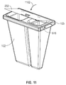
- the container top 103 includes, according to the present example, two openings 602, 604. These openings 602, 604, according to the example, are funnel shaped as shown in FIG. 6 .
- the first opening 602 corresponds to a first inner compartment 606 in the container main body 102.
- the second opening 604 corresponds to a second compartment 608 in the container main body 102.
- the first compartment 606 is separated from the second compartment 608 by a container gap opening 613, as shown in FIG. 6 .
- Each compartment 606, 608, has a bottom 610, 612, respectively.
- Each bottom portion 610, 612, of the container main body 102 is constructed with additional container body material making the bottoms 610, 612 thicker than the other walls of the container main body 102. This thicker bottom material 610, 612, helps facilitate the container main body to fully expand to its empty ready to use shape.
- the container main body 102, before use, may be provided in a compressed state just below the top 103. This reduced volume is advantageous for storing and shipping the container 101.
- the container main body 102 After removal of a container 101 from a protective packaging by supporting the container 101 from the top, such as by a user holding the handles 618, 802, the container main body 102 due to the added container material at the bottom 610, 612 of the container main body 102 through the force of gravity encourages the container main body 102 to fully expand to its empty ready to use shape as shown in FIG. 6 . That is, the container 101, in the example shown in FIG. 6 , is self-expanding to its full ready to use shape when supported by the top 103.
- the top 103 includes a flat top surface 616 around the two openings 602, 604.
- a lid 202 can be located on this top surface 616 to cover the openings 602, 604.
- the lid 202 includes a retaining means 614 such as an adhesive surface that when contacting the flat top surface 616 will create an adhesive bond and retain the lid 202 secured on top of the top 103, thereby covering the openings 602, 604 to prevent objects in the compartments 606, 608 from spilling out of the container 101.
- the lid 202 is secured along one edge of the lid 202 to an edge of the top surface 616 allowing the lid 202 to be rotated from an open position away from the top surface 616 to a closed position where the lid 202 makes contact with the top surface 616, thereby covering the openings 602, 604 in the top 103.
- the adhesive 614 may be exposed by peeling a film cover from the adhesive surface 614 allowing the adhesive then to bond to the top surface 616 when the lid 202 is rotated on top of the top surface 616.
- the top lid 202 when covering the openings 602, 604 in the top 103 additionally creates a fluid tight seal preventing the fluid from objects contained in the one or more compartments 606, 608 from escaping from the container 102.
- the container 101 can therefore be disposed of safely without exposing users to hazardous materials contained in the container 101.
- FIG. 7 the construction and assembly of the container 101 of FIG. 6 is shown.
- the container main body 102 is held secured to the underside of the top 103 by a retaining ring 706.
- the four broken lines show the direction of assembly of the container main body 102, the container top 103, and the rigid retaining ring 706.
- the container main body includes a fold 704 along the perimeter of the top portion of the container main body 102.
- the retaining ring 706 is fitted under the fold 704 and then the top 103 is fitted on top of the fold with the rigid retaining ring and the top 103 creating a sandwich with the fold material 704 securing the container main body to the top 103 in a fluid tight seal.
- the lid 202 is a rigid or semi-rigid material that is attached to an edge of the container main body 102 allowing the lid 202 to be rotated over the top 103 when the container 101 is fully assembled.
- the two compartments 606, 608, of the container main body 102 are separated by an opened gap 613 between the two compartments 606, 608.
- the open gap continues up towards the top portion of the container main body 102 until reaching a top fold region 702 extending from a rear surface of the container main body 102 to a front surface of the container main body 102 as shown.
- FIG. 8 shows a top perspective view of the container 101 with the lid 202 open away from the top surface 616 of the top 103.
- the openings 602, 604 are funnel shaped with gradually sloping funnel surface 804, 806, respectively extending downward from the top surface 616 into the respective compartments 606, 608.
- the gradually inward sloping surface 804 of the first opening 602 and the gradually inward sloping surface 806 of the second opening 604 help guide objects deposited in the respective openings 602, 604 towards a center region of each opening 602, 604 while being deposited in the respective compartments 606, 608.
- This guiding feature of the surfaces 804, 806 of the openings 602, 604, optimally locates the falling objects in the detection region just below the bottom of the surfaces of 804,806, of the funnel shaped openings 602, 604.
- the detection region corresponds to a region across each opening 602, 604, covered by a plurality of optical beams being emitted by optical emitters and sensed by matching optical sensors located along the inner surface of a ring center opening of the OSR 104 of the Monitor System 100. These beams traverse and blanket the openings 602, 604, according to various embodiments, between the rear portion of the container 101 and the front portion of the container 101, while being supported by the top 103 on the OSR 104 of the Monitor System 100.
- each beam traverses the detection region just below the gradually inward sloping surfaces 804, 806, of the openings 602, 604 of the top 103, each beam, according to the present example, from an optical emitter to its matching optical sensor on the opposing inner surface of the OSR 104 traverses across two container walls of the container main body 102, toward the upper portion of the main container body 102.
- the material and construction of these container walls is suitable for transmitting these optical beams without significant attenuation of optical energy thereby allowing each beam to reach its matching optical sensor with sufficient energy to be detected.
- the walls of the container body 102 at least about the top portion of the main container 102 just below the gradually inwardly sloping surfaces 804, 806, of the openings 602, 604 can be constructed of an optically transmissive material that allows most of the beam energy to transmit and pass through the wall of the container main body 102.
- a material called CLEAR which manufactured and distributed by Dupont Corporation, may be suitable for use in construction of the walls of the container main body 102 such that IR beams may transmit substantially unattenuated through these walls of the container main body 102, thereby delivering the beam to the matching optical sensor.
- FIGS. 9 and 10 show in more detail the construction and arrangement of the underside of the top 103.
- a rigid retaining ring 706 is shaped to mate into a recessed portion 902 of the underside of the top 103.
- the fold 704 of the container main body 102 is received in the recessed portion 902 of the underside of the top 103, and is secured therein by the mating of the rigid retaining ring 706 into the recessed portion 902 as shown.
- the top 103 at its recessed portion 902 receives the matching rigid retaining ring 706 and the fold 704 into the recessed portion 902.
- the rigid retaining ring 706 and fold 704 are secured and retained in the recessed portion 902 of the underside of the top 103.
- the locking arrangement of the rigid retaining ring 706, the fold 704 of the main container body 102, and the recessed portion 902 of the top 103 also creates a fluid tight seal in this region of the container 101. That is, fluid from the objects (e.g., surgical objects, sponges, etc.) contained in the compartments of the container main body 102 will not leak through this sealed region formed by the mating and locking arrangement of the rigid retaining ring 706, the fold 704 of the main container body 102, and the recessed portion 902 of the underside of the top 103.
- the objects e.g., surgical objects, sponges, etc.
- FIG. 11 illustrates with arrow 1102 how the lid can be rotated 1102 onto the top surface 616 of the top 103.
- a retaining feature or adhesive is located in at least one surface of the top surface 616 of the top 103 and the underside surface of the lid 202.
Landscapes
- Health & Medical Sciences (AREA)
- Engineering & Computer Science (AREA)
- Life Sciences & Earth Sciences (AREA)
- Surgery (AREA)
- Physics & Mathematics (AREA)
- Heart & Thoracic Surgery (AREA)
- General Health & Medical Sciences (AREA)
- Veterinary Medicine (AREA)
- Biomedical Technology (AREA)
- Public Health (AREA)
- Animal Behavior & Ethology (AREA)
- Nuclear Medicine, Radiotherapy & Molecular Imaging (AREA)
- Medical Informatics (AREA)
- Anesthesiology (AREA)
- Vascular Medicine (AREA)
- Cardiology (AREA)
- Physiology (AREA)
- Pulmonology (AREA)
- Biophysics (AREA)
- Pathology (AREA)
- Hematology (AREA)
- Molecular Biology (AREA)
- Mathematical Physics (AREA)
- Theoretical Computer Science (AREA)
- General Physics & Mathematics (AREA)
- Mechanical Engineering (AREA)
- External Artificial Organs (AREA)
- Accommodation For Nursing Or Treatment Tables (AREA)
Description
- The present disclosure generally relates to surgical object monitoring systems, and more particularly to a container for use with surgical object (e.g., a surgical sponge) monitoring system that can monitor and track surgical objects and the fluid of a patient during a surgical procedure.
- Surgical object monitoring systems have attempted to keep track of surgical objects with varying degrees of success. Some monitoring systems have relied almost entirely on manual counting of objects, such as sponges, while being used in a surgical operating room. This manual tracking process can be particularly error prone, which can result in unfortunate cases of surgical objects remaining inside patients after a surgical operation. Some monitoring systems have attempted to utilize complex and expensive technical solutions utilizing objects modified with RFID devices and/or barcodes to be scanned before, during, and after surgical procedures. These conventional monitoring systems continue to experience problems in attempting to keep track, and possibly locate lost objects such as sponges, that remain inside a patient. These conventional monitoring systems also fail to monitor fluids, such as blood, serum, or other fluids, that can be lost by a patient during a surgical procedure.
-
US5629498 , on which the preambles of claims 1 and 12 are based, describes an automated tracking device having a rigid support frame 30,54 that supports a container 32 adapted to receive sponges utilized in surgical procedures. The rigid frame 30,54 is configured to allow for easy deployment and removal of the container 32 from the tracking device so that the container, with contents, can be discarded once finished with.US20080308441 relates to a medical dispenser adapted to contain lancets or equivalent medial instruments. The container comprises lid which is connected to the top of the container by a living hinge. - According to the invention, a container according to claim 1, a method of use according to claim 12 and a system according to claim 16 are provided. Preferred embodiments are provided in the dependent claims.
- The accompanying figures in which like reference numerals refer to identical or functionally similar elements throughout the separate views, and which together with the detailed description below are incorporated in and form part of the specification, serve to further illustrate various embodiments and to explain various principles and advantages all in accordance with the present disclosure, in which:
-
FIGs. 1 to 5 are perspective views of an example of a monitoring system for use during a surgical procedure, according to the present disclosure; -
FIG. 6 is a front perspective view of an example of a container suitable for use in a monitoring system, according to the present disclosure; -
FIG. 7 is a front perspective view of the example container ofFIG. 6 partly disassembled to illustrate construction and assembly thereof, according to the present disclosure; -
FIG. 8 is a top perspective view of the example container ofFIG. 6 , according to the present disclosure; -
FIG. 9 is a front-bottom perspective view of the example container ofFIG. 6 , according to the present disclosure; -
FIG. 10 is a front-bottom perspective view of a portion of the example container ofFIG. 6 , according to the present disclosure; and -
FIG. 11 is a front-right perspective view of the example container ofFIG. 6 , according to the present disclosure. - As required, detailed embodiments are disclosed herein; however, it is to be understood that the disclosed embodiments are merely examples and that the devices, systems and methods described herein can be embodied in various forms. Therefore, specific structural and functional details disclosed herein are not to be interpreted as limiting, but merely as a basis for the claims and as a representative basis for teaching one of ordinary skill in the art to variously employ the disclosed subject matter in virtually any appropriately detailed structure and function. Further, the terms and phrases used herein are not intended to be limiting, but rather, to provide an understandable description. Additionally, unless otherwise specifically expressed or clearly understood from the context of use, a term as used herein describes the singular or the plural of that term.
- The terms "a" or "an", as used herein, are defined as one or more than one. The term "plurality", as used herein, is defined as two or more than two. The term "another", as used herein, is defined as at least a second or more. The terms "including" and "having," as used herein, are defined as comprising (i.e., open language). The term "coupled," as used herein, is defined as "connected," although not necessarily directly, and not necessarily mechanically. "Communicatively coupled" refers to coupling of components such that these components are able to communicate with one another through, for example, wired, wireless or other communications media. The term "communicatively coupled" or "communicatively coupling" includes, but is not limited to, communicating electronic control signals by which one element may direct or control another. The term "configured to" describes hardware, software or a combination of hardware and software that is adapted to, set up, arranged, commanded, altered, modified, built, composed, constructed, designed, or that has any combination of these characteristics to carry out a given function. The term "adapted to" describes hardware, software or a combination of hardware and software that is capable of, able to accommodate, to make, or that is suitable to carry out a given function.
- The terms "controller", "computer", "server", "client", "computer system", "computing system", "personal computing system", or "processing system" describe examples of a suitably configured processing system adapted to implement one or more embodiments of the present disclosure. Any suitably configured processing system is similarly able to be used by embodiments of the present disclosure. A processing system may include one or more processing systems or processors. A processing system can be realized in a centralized fashion in one processing system or in a distributed fashion where different elements are spread across several interconnected processing systems.
- The terms "computing system", "computer system", and "personal computing system", describe a processing system that includes a user interface and which is suitably configured and adapted to implement one or more embodiments of the present disclosure. The terms "network", "computer network", "computing network", and "communication network", describe examples of a collection of computers and devices interconnected by communications channels that facilitate communications among users and allows users to share resources. The terms "wireless network", "wireless communication network", and "wireless communication system", similarly describe a network and system that communicatively couples computers and devices primarily or entirely by wireless communication media. The terms "wired network" and "wired communication network" similarly describe a network that communicatively couples computers and devices primarily or entirely by wired communication media.
- Referring to
FIG. 1 , an example of a surgical object and fluid monitoring system (Monitor System) 100 is shown, according to various embodiments of the present disclosure. - The Monitor System 100 supports a
container 101 that can receive and contain surgical objects, including but not limited to sponges and fluid-retaining sponges. Thecontainer 101, according to various embodiments is disposable. Thecontainer 101, according to various embodiments is constructed of lightweight plastic or polymer materials and film. Thecontainer 101, according to the present example, includes a containermain body 102 that is directly mechanically coupled to acontainer top 103. According to various embodiments, the containermain body 102 and thecontainer top 103 are mechanically coupled in a fluid-tight seal. - The container
main body 102, according to the present example, comprises aflexible film bag 102 that can be easily compressed and collapsed into a small volume adjacent to the underside of thecontainer top 103. When thecontainer top 103 is supported in a horizontal orientation, as shown inFIG. 1 , theflexible film bag 102 easily falls down from the top 103 (by the force of gravity) thereby fully expanding and conforming to its fully expanded open shape, as shown inFIG.1 . The containermain body 102 is therefore self-expanding from its compressed volume shape to its fully expanded ready-to-use shape, by the force of gravity. - In the present example, as illustrated in
FIG. 1 , thecontainer 101 is supported by itstop 103 that is securely supported by an optical sensor ring (OSR) 104 of the MonitorSystem 100. The OSR 104 is mechanically coupled to, and supported by, avertical spine 106 of the MonitorSystem 100. Theflexible bag 102 falls down from the supportedtop 103 by the force of gravity. The emptyflexible bag 102, when supported by the OSR 104, fully expands to its open shape ready-to-use with the MonitorSystem 100. - As shown in the example of
FIG.1 , theflexible bag 102 has a tapering shape that tapers from wider cross-section about thetop 103 to narrower cross-section towards the bottom of thebag 102. Thiscontainer 101 is easy to transport and store, especially with the containermain body 102 compressed/collapsed to a reduced volume shape adjacent to the underside of thetop 103. - For example, the empty, compressed,
container 101 can be easily stored in a sealed storage package (not shown) that keeps thecontainer 101 sanitary and ready to use in a clean room such as a surgical operating room. Then, when a user (e.g., a surgical nurse or assistant) opens the sealed storage package and removes therefrom thecontainer 101, by only holding thetop 103 by its handles (as shown inFIG. 3 ), the container self-expands to its full ready-to-use shape by the force of gravity. The user does not have to manipulate the containermain body 102 to cause thecontainer 101 to fully expand to its full open shape ready to use. The user can support thecontainer top 103 in a horizontal orientation (e.g., by holding thetop 103 by its handles in a natural gesture similar to carrying a tray) and the empty containermain body 102 will self-expand (e.g., fully expand to its open ready-to-use shape). Thiscontainer 101 design provides a user friendly container product that is easy to store and transport, easy to extract out of the OSR for disposal of the container and its content, and easy to dispose of after use. - As shown in
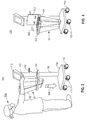
FIG. 1 , theMonitor System 100 comprises avertical spine 106 that is maintained in a substantially vertical orientation and supported by abase 108 of the MonitorSystem 100. Thebase 108 may include, according to various embodiments,several wheels 110 that allow the user to easily move (i.e., push-pull) the Monitor System 100 to a desired location for use. Ahandle 116 extends from thevertical spine 106 such that a user of the MonitorSystem 100, for example, can grab thehandle 116 and thereby pull or push the Monitor System 100 on itswheels 110 to a desired location.FIG. 2 shows a user with ahand 208 grabbing thehandle 116 of theMonitor System 100. - As shown in
FIG. 1 , theMonitor System 100 includescontroller unit 112 that is supported at the top of thevertical spine 106. Thecontroller unit 112, according to the present example, includes a touch screenliquid crystal display 114 that provides a user interface for a user of theMonitor System 100. Any type of touch screen display technology may be used in theMonitor System 100, as may be desired for various applications. - With reference to
FIG. 2 , theMonitor System 100 is shown with thecontainer 101 having received an object, such as a fluid filled sponge, 204 within an internal compartment of thecontainer 101. The containermain body 102 can include one or more compartments that each can receive and contain objects, such as fluid filled sponges, that are dropped into thecontainer 101 through one or more ports oropenings 206 at the top 103 of thecontainer 101. - A
top lid 202 may be used to cover the one ormore openings 206 on thecontainer top 103 after the container has received one ormore objects 204 and its use has been completed. Thetop lid 202 will cover the one ormore openings 206 and, according to certain embodiments, will create a fluid-tight seal with thecontainer top 103. This facilitates removal of thecontainer 101 from theMonitor System 100 as well as disposal of thecontainer 101. Thecontainer 101 with thetop lid 202 covering the one ormore openings 206, and optionally creating a fluid-tight seal at thecontainer top 103, securely contains theobject 204 in a compartment inside thecontainer 101. With theobject 204, such as a fluid-filled sponge, being securely contained and sealed within thecontainer 101, thecontainer 101 can be easily removed from theMonitor System 100 and disposed accordingly without concern for leakage of bio-contaminated and/or hazardous objects or fluids from thecontainer 101. - As shown in
FIG. 3 , theuser 302 can hold thecontainer 101 by thecontainer top 103, such as by handles on either side of thecontainer top 103. The container main body (e.g., a flexible bag) 102 fully expands to its ready-to-use shape and theempty container 101 can easily be lowered 304 by theuser 302 onto theoptical sensor ring 104 which then acts as support for thecontainer 101. Thearrow 304 indicates how theuser 302 lowers thecontainer 101 into the center opening of theoptical sensor ring 104. Of course, the reverse procedure can be used to remove thecontainer 101 from theOSR 104. By lifting thecontainer 101, e.g., a usedcontainer 101 containing one ormore objects 204, theuser 302 can remove thecontainer 101 from theOSR 104 and from theMonitor System 100. The user can then be safely and conveniently dispose of the removedcontainer 101. - It should be noted that while the
optical sensor ring 104 is shown as a continuous rigid ring structure in the present example, according to other embodiments theoptical sensor ring 104 could have a hinged portion (not shown) that is rotatable away from the other portions of theOSR 104. For example, a left portion or a right portion of theOSR 104 could be the hinged rotatable portion. The hinged rotatable portion could be secured (e.g., using a locking or latching device) to the remaining structure of theOSR 104 to form the continuous ring shape of theOSR 104. When acontainer 101 is full ofobjects 204, and its total weight may be significant, theuser 302 could avoid having to lift thefull container 101 from theOSR 104. By opening the locking or latching device at the hinged rotatable portion, the user can hold the handles at the top 103 of thefull container 101 and remove it from theOSR 104 by lateral movement - to the left or right of theOSR 104. Theuser 302 would not have to lift thefull container 101 higher than its current level while supported by theOSR 104. - As shown in
FIG. 4 , after thecontainer 101 is placed through the center opening of, and supported by, theOSR 104, thetop lid 202, according to one example, can be rotated up-and-to-the-rear of thecontainer top 103, as indicated by thearrow 402. According to certain embodiments, thetop lid 202 then remains vertically supported by thevertical spine 106, as shown inFIG. 4 . Optionally, a small magnet may be embedded in thetop lid 202. When thetop lid 202 is resting vertically against thevertical spine 106 thetop lid 202 is removably secured to thevertical spine 106 by magnetic force between the small magnet in thetop lid 202 and a metallic surface of thevertical spine 106. A user can, as necessary, pull and remove thetop lid 202 from thevertical spine 106 and rotate thelid 202 back onto the top surface of thecontainer top 103. - The
top lid 202 provides a splash guard for any fluids that may be splashed by fluid-containing objects being placed into thecontainer 101 through the one ormore openings 206. Additionally, thecontainer lid 202 can include writing or symbols, as illustrated inFIG. 4 , to visually help guide the user to locate theappropriate opening 206 to drop an object into thecontainer 101. As shown inFIG. 4 , there are two compartments within thecontainer 101. One compartment holds smaller objects (e.g. small fluid-containing sponges), while thesecond opening 206 is for a second compartment in thecontainer 101 that holds larger objects (e.g. large fluid-containing sponges). In this way, according to the present example, thecontainer 101 can be used to not only containobjects 204, but also to help sort these objects in the corresponding compartments. Theobjects 204 are sorted by attributes of each group of objects such as by size, thickness, or other dimensions, of sponges being used in a surgical procedure. According to various embodiments, other attributes ofobjects 204 can be used for sorting theobjects 204 in the different compartments within thecontainer 101. - Referring to
FIG. 5 , theuser 502 can touch thetouch screen 114 of theMonitor System 100 to communicate information with theMonitor System 100. For example, theuser 502 can use a finger of the hand, or a stylus, to touch locations on the touch sensitive surface of thetouch screen 114. In this way, theuser 502 can communicate commands and/or data to theMonitor System 100, and optionally configure parameters of theMonitor System 100, in accordance with a particular implementation of theMonitor System 100. - The
user 502 can enter configuration information into theMonitor System 100 to let theMonitor System 100 know, for example, how many compartments are in thecontainer 101 and the types of objects and their attributes that may be expected to be placed in these compartments. Additionally, theuser 502 can provide information to theMonitor System 100 to inform theMonitor System 100 of how many objects to expect to be placed in each of the compartments in thecontainer 101. - The
touch screen 114 provides a user interface that not only receives information from theuser 502, but also displays information to the user. In this way, theuser 502 can be informed of certain events that occur with theMonitor System 100 and certain conditions experienced by theMonitor System 100. For example, thetouch screen display 114 can display a count of the number of objects, such as fluid-filled sponges, that have been deposited in each of the compartments in thecontainer 101. Additionally, for example, thetouch screen display 114 can display to theuser 502 the approximate amount of fluid by weight (or by calculated volume) that has been accumulated in the compartments of thecontainer 101. - Once the
Monitor System 100 has been configured and is ready to use, the user places each object (e.g., such as a fluid-filled sponge removed from a patient during a surgical procedure) at one of the one ormore openings 206 in the top 103 of thecontainer 101, and then allows the object to drop through theparticular opening 206 and down into a receiving compartment within the containermain body 102. - Each of the one or
more openings 206, according to the present example, comprises a funnel shape with a gradual inward sloping surface from the top surface of thecontainer top 103 down toward the inside of a compartment in the containermain body 102. This funnel shape helps guide the objects being placed at theopening 206 into the particular compartment of thecontainer 101. Also, this funnel shape more reliably places the falling object at a generally central region of theopening 206. By dropping theobject 204 down from a central region of theopening 206, a plurality of sensors in theOSR 104 just below theopening 206 can more reliably sense/detect the falling object, as will be discussed below. - One or more sets of optical emitters located along an inner surface of the
OSR 104 emit respective one or more optical beams (e.g., infrared "IR" beams) across a central opening of theOSR 104 aimed at respective one or more optical sensors located along an opposing inner surface of theOSR 104. For example, a first group of alternating optical emitters and optical sensors may be located along an inner surface of a rear portion of theOSR 104. - Additionally, a second group of alternating optical sensors and optical emitters (opposing the first group of optical emitters and sensors) may be located along an inner surface of a front portion of the
OSR 104. Each optical emitter is matched to an opposing optical sensor to create an optical beam that traverses across the center opening of theOSR 104. - A detection region is formed by a plurality of optical beams spanning across the front portion and rear portion of the center opening of the
OSR 104. The detection region is just below the end of each funnel shaped port or opening 206 in thecontainer 101. - To facilitate the optical beams traversing across the center opening of the
OSR 104 while thecontainer 101 is supported on theOSR 104, according to various embodiments, the construction and material of the walls of the containermain body 102, at least in the detection region just below the funnel shaped opening(s) 206, are optically transparent over the relevant wavelength and frequency range of the Infra-Red (IR) optical beam, e.g., over IR wavelength and frequency range of the optical beam sensed by the sensor. - Optionally, the material and construction of the walls of the container
main body 102, at least in the detection region just below the funnel shaped opening(s) 206, can be optically transmissive or optically transflective, at the relevant wavelength and frequency range of the optical beam. This material and construction is designed to enhance the ability of each of the optical beams emitted from an emitter device at the inner surface about the ring center opening of one portion of theOSR 104 to reach and be detectable by the matching sensor device at the opposing inner surface about the ring center opening of another portion of theOSR 104. - For example, according certain embodiments, Dupont Corporation makes a clear polyethylene film product called CLEAR that provides optical qualities suitable for use in the construction and material of the walls of the container
main body 102, at least in the detection region just below the funnel shaped opening(s) 206. Another desired aspect of the construction of the walls of thecontainer 101, at least in the detection region just below the funnel shaped opening(s) 206, is that the walls traversed by an optical beam be oriented substantially perpendicular to the axis of the optical beam. This perpendicular wall orientation relative to the optical beam axis enhances the amount of optical energy that passes through the wall and thereby enhances the ability of the beam to reach and be detectable by the corresponding optical sensor device. - Therefore, in view of the discussion above, an object (e.g., a sponge) placed at the
opening 206 while dropping into the corresponding compartment in thecontainer 101 will have to pass through the detection region covered by the one or more optical beams (e.g., IR beams). The one or more beams traverse across this detection region such that when each object is dropped into anopening 206 of thecontainer 101 at least one beam is broken by the falling object while the object passes the detection region. The break of the beam is sensed by the respective optical sensor and a beam break signal is sent from the optical sensor to a processor/controller in theMonitor System 100, to indicate that an object has been dropped into theparticular port opening 206. - A more sophisticated approach to sensing and monitoring an object being dropped through a detection region is provided here according to various embodiments. A plurality of beams (time and spatially multiplexed), between the inner surface of the rear portion of the
OSR 104 and the inner surface of the front portion of theOSR 104, are spaced apart a known distance from each other in the detection region. After at least one beam break is detected by the processor/controller the sensors and the processor/controller can continuously monitor the beam break(s) while the object continues to fall past the detection region. The beam-break-sense monitoring, for example, can be repeated every 10 milliseconds until all of the optical beams are sensed again (i.e., no beam breaks detected). The spatial location of the beam break(s) would signify the specific port (i.e., opening 206) at the top of the container through which an object enters. - Key objectives of various embodiments include, but are not limited to, reliably sorting the object types (in this example two different sponge types correspond to two
respective openings 206, i.e., two ports, at the top of the container); providing a valid count of the appropriate object type thrown in the container (eliminating/minimizing false positives); and estimating the fluid content in each such object. - The sorting of object type, according to the present example, is done by providing two ports on top of the container, each port identified with a specific sponge type (this has been described somewhat elsewhere in the present disclosure). Each port is blanketed by a set of IR beams (see, for example, FIG. 14), and each set of IR beams is multiplexed, scanned and monitored by the processor/controller. The processor/controller can then identify the sponge type that was dropped based on which port the IR beam(s) was interrupted.
- In order to achieve a reliable object (e.g. a used sponge) count (and eliminate false positives), the key is in the use of an "intelligent" algorithm that uses information from the sensor beam breaks and the incremental weight change measurement (such as using a load cell that will be more fully described below) when a sponge (or object) is thrown in the container through one of the ports. Namely, with general reference to FIGs. 14, 15, and 16, of
US8692140 , when an object passes through the beams 1402, 1404, a beam first "breaks" and then "unbreaks" at the tail-end of the passage of the object. The object will fall to the bottom of the container within a maximum time, ΔTdmax 1512, and an incremental weight change, ΔW 1610 will be measured at ΔTW 1606 (ΔTdmax 1512 plus a Delta Ts 1604, i.e., plus a noise signal settling time) relative to the baseline reference weight established at TBB 1508 - when the beam "unbreaks" after a "break"). So, a valid count is recorded only if ΔW 1610 is valid and it is within the pre-stored weight range of fluid content (i.e., between zero to fully saturated sponge weight). The following three exceptions should be noted, however. - First, if the beam is broken (e.g., by inserting one's fingers through port or sponge stuck at the port), no count will be registered because either the beam is broken and no weight change - or - the beam is continuously broken with or without weight change. Either case would violate the rules for a valid count, as has been described above.
- Secondly, if the beam is broken properly (with the "break" and "unbreak" sequence in place) but the incremental weight ΔW 1610 is outside the prescribed range, the count is considered invalid.
- Third, if a foreign weight is placed on the container (e.g. tray, tongs, etc.), the temporary or permanent increase of the overall weight of the container due to the foreign weight will not hamper the measurement of the actual incremental weight ΔW 1610 of a sponge (object) that has traversed the optical sensors; hence the sponge will be counted as valid. Note that ΔW 1610 is a relative measurement as shown in FIG. 16.
- Once a valid sponge (object) is detected in the container and counted based on the above rules, then for each ΔW 1610 measured the incremental fluid content of the container is calculated by subtracting from ΔW 1610 the pre-stored dry weight (Wdry) of the sponge type. This incremental fluid content is accumulated to the running total Fluid count maintained by the Monitor.
- The fluid content of the object extracted/calculated from its incremental weight ΔW 1610 is used to accumulate the total fluid count. Hence, any extraneous weight placed on the container (or removed via evaporation of fluid from the container) would not, and should not, factor into the accumulated total fluid count maintained by the Monitor.
- Now, continuing with the description of the
example Monitor System 100, and with particular reference toFIGs. 4 and5 , a plurality of optical emitter beams blanket the region just below the one ormore openings 206 at the top 103 of thecontainer 101. The one or more optical emitter beams pass from a first inner side of theOSR 104, through the opposing walls of the containermain body 102, and across to and below the one ormore funnel openings 206, to one or more optical sensors located in an opposing second inner side of theOSR 104. The one or more optical beams, therefore, traverse the ring center opening from across opposing inner sides of the containermain body 102 just below the funnel shapedopenings 206 of thecontainer top 103. The optical beams, according to various embodiments, pass through the walls of the containermain body 102, at least about the detection region where the optical beams traverse the ring center opening of theOSR 104 from across opposing inner sides of the containermain body 102. - After the
Monitor System 100 detects that an object has been dropped into the compartment within thecontainer 101, e.g. by detecting one or more beams between optical emitters and optical sensors have been broken, theMonitor System 100 can additionally monitor the incremental weight change due to the object that has been dropped in thecontainer 101. After an object is dropped into the compartment of thecontainer 101, the object after traversing one or more of the optical beams in the detection region of thecontainer 101, will further drop and make contact either 1) with the bottom of the container main body 102 (corresponding to an empty compartment of the container 101), or 2) with the object(s) already resting on the bottom. When the object drops inside a compartment of thecontainer 101 and delivers its incremental weight to thecontainer 101, such as when the object reaches the bottom of thecontainer 101, the object's weight can be established by theMonitor System 100. - According to certain embodiments, the
Monitor System 100 includes an electronic load cell mechanically coupled to theOSR 104 that supports thecontainer 101, and thereby senses the weight of thecontainer 101 and its contents. Thus, the load cell can provide a signal that indicates the incremental weight of the object that has been dropped into thecontainer 101, as the weight is transferred from thecontainer 101 to theOSR 104, and thereby transferred to the electronic load cell in theMonitor System 100. In this way, theMonitor System 100 detects an object being dropped into thecontainer 101 and establishes the incremental weight of the object that was just dropped in thecontainer 101. - Based on information in the
Monitor System 100, such as information that theuser 502 configured in theMonitor System 100 by using thetouch screen display 114, the attributes of the object expected to be dropped into a particular compartment in thecontainer 101 are known to theMonitor System 100. In the case where theobject 204 in thecontainer 101 is carrying fluid, the additional weight of the fluid in theobject 204 will also be part of the total weight of the dropped object that is detected by the load cell and theMonitor System 100. By subtracting the known approximate weight of theobject 204 before being filled with fluid from the total weight of the dropped object 204 (e.g., which is fluid filled) theMonitor System 100 can establish the weight of the fluid in the object that was dropped into thecontainer 101. - This incremental weight of fluid can additionally indicate a certain volume of fluid when the type of fluid is known. For example, for blood filled sponges that are dropped into the
container 101 theMonitor System 100 calculates, based on the cumulative measured weight of the blood contained in the sponges, the approximate amount of total volume of blood removed (via the sponges) from the patient during a surgical procedure. That is, the weight of the blood carried in the sponges can be used to approximate the cumulative volume of the blood loss. - By information being displayed to the user via the
touch screen display 114, for example, theMonitor System 100 can inform the user of the total count of objects being dropped in thecontainer 101, the type of objects sorted in a compartment in thecontainer 101, and an estimation of the total volume of fluid loss (e.g., blood loss) from a patient during surgical procedure. That is, according to various embodiments, the volume estimate would be based on the weight of the fluid carried within the objects being deposited into thecontainer 101. One or more controllers (or processors) in theMonitor System 100 can be used to monitor the objects being dropped in thecontainer 101 and then calculate and display via thetouch screen display 114 valuable information to the user, such as the count of the total number of objects being dropped into thecontainer 101, sorted by type of object that is dropped into thecontainer 101, and a calculated estimate of fluid loss volume from a patient as indicated by the weight of the fluid in the fluid-filledobjects 204 being dropped into thecontainer 101. - With reference to
FIGS. 6 to 11 , a more detailed discussion of anexample container 101 suitable for use with theMonitor System 100 is provided below. As shown inFIG. 6 , thecontainer 101 is shown fully assembled and ready to use. Thecontainer 101 includes a containermain body 102 and acontainer top 103. Thecontainer top 103 includes, according to the present example, twoopenings openings FIG. 6 . Thefirst opening 602 corresponds to a firstinner compartment 606 in the containermain body 102. Thesecond opening 604 corresponds to asecond compartment 608 in the containermain body 102. Thefirst compartment 606 is separated from thesecond compartment 608 by a container gap opening 613, as shown inFIG. 6 . - Each
compartment bottom portion main body 102 is constructed with additional container body material making thebottoms main body 102. This thickerbottom material main body 102, before use, may be provided in a compressed state just below the top 103. This reduced volume is advantageous for storing and shipping thecontainer 101. After removal of acontainer 101 from a protective packaging by supporting thecontainer 101 from the top, such as by a user holding thehandles main body 102 due to the added container material at the bottom 610, 612 of the containermain body 102 through the force of gravity encourages the containermain body 102 to fully expand to its empty ready to use shape as shown inFIG. 6 . That is, thecontainer 101, in the example shown inFIG. 6 , is self-expanding to its full ready to use shape when supported by the top 103. - The top 103, according to the present example, includes a flat
top surface 616 around the twoopenings lid 202 can be located on thistop surface 616 to cover theopenings lid 202 includes a retaining means 614 such as an adhesive surface that when contacting the flattop surface 616 will create an adhesive bond and retain thelid 202 secured on top of the top 103, thereby covering theopenings compartments container 101. - According to one embodiment, the
lid 202 is secured along one edge of thelid 202 to an edge of thetop surface 616 allowing thelid 202 to be rotated from an open position away from thetop surface 616 to a closed position where thelid 202 makes contact with thetop surface 616, thereby covering theopenings adhesive surface 614 allowing the adhesive then to bond to thetop surface 616 when thelid 202 is rotated on top of thetop surface 616. - According to certain embodiments, the
top lid 202 when covering theopenings more compartments container 102. Thecontainer 101 can therefore be disposed of safely without exposing users to hazardous materials contained in thecontainer 101. - Referring to
FIG. 7 , the construction and assembly of thecontainer 101 ofFIG. 6 is shown. The containermain body 102 is held secured to the underside of the top 103 by a retainingring 706. The four broken lines show the direction of assembly of the containermain body 102, thecontainer top 103, and therigid retaining ring 706. - The container main body includes a
fold 704 along the perimeter of the top portion of the containermain body 102. The retainingring 706 is fitted under thefold 704 and then the top 103 is fitted on top of the fold with the rigid retaining ring and the top 103 creating a sandwich with thefold material 704 securing the container main body to the top 103 in a fluid tight seal. - According to the present example, the
lid 202 is a rigid or semi-rigid material that is attached to an edge of the containermain body 102 allowing thelid 202 to be rotated over the top 103 when thecontainer 101 is fully assembled. As shown inFIG. 7 , the twocompartments main body 102 are separated by an openedgap 613 between the twocompartments main body 102 until reaching atop fold region 702 extending from a rear surface of the containermain body 102 to a front surface of the containermain body 102 as shown. -
FIG. 8 shows a top perspective view of thecontainer 101 with thelid 202 open away from thetop surface 616 of the top 103. Theopenings funnel surface top surface 616 into therespective compartments sloping surface 804 of thefirst opening 602 and the gradually inwardsloping surface 806 of thesecond opening 604 help guide objects deposited in therespective openings opening respective compartments surfaces openings openings - The detection region corresponds to a region across each
opening OSR 104 of theMonitor System 100. These beams traverse and blanket theopenings container 101 and the front portion of thecontainer 101, while being supported by the top 103 on theOSR 104 of theMonitor System 100. - Because these beams traverse the detection region just below the gradually inward sloping
surfaces openings OSR 104 traverses across two container walls of the containermain body 102, toward the upper portion of themain container body 102. The material and construction of these container walls is suitable for transmitting these optical beams without significant attenuation of optical energy thereby allowing each beam to reach its matching optical sensor with sufficient energy to be detected. - The walls of the
container body 102, at least about the top portion of themain container 102 just below the gradually inwardly slopingsurfaces openings main body 102. For example, a material called CLEAR, which manufactured and distributed by Dupont Corporation, may be suitable for use in construction of the walls of the containermain body 102 such that IR beams may transmit substantially unattenuated through these walls of the containermain body 102, thereby delivering the beam to the matching optical sensor. -
FIGS. 9 and 10 show in more detail the construction and arrangement of the underside of the top 103. Arigid retaining ring 706 is shaped to mate into a recessedportion 902 of the underside of the top 103. Thefold 704 of the containermain body 102 is received in the recessedportion 902 of the underside of the top 103, and is secured therein by the mating of therigid retaining ring 706 into the recessedportion 902 as shown. - When the
rigid retaining ring 706 is passed underneath thefold 704 of themain container body 102, the top 103 at its recessedportion 902 receives the matchingrigid retaining ring 706 and thefold 704 into the recessedportion 902. Therigid retaining ring 706 and fold 704 are secured and retained in the recessedportion 902 of the underside of the top 103. - According to various embodiments, the locking arrangement of the
rigid retaining ring 706, thefold 704 of themain container body 102, and the recessedportion 902 of the top 103, also creates a fluid tight seal in this region of thecontainer 101. That is, fluid from the objects (e.g., surgical objects, sponges, etc.) contained in the compartments of the containermain body 102 will not leak through this sealed region formed by the mating and locking arrangement of therigid retaining ring 706, thefold 704 of themain container body 102, and the recessedportion 902 of the underside of the top 103. - Lastly,
FIG. 11 illustrates witharrow 1102 how the lid can be rotated 1102 onto thetop surface 616 of the top 103. Optionally, a retaining feature or adhesive is located in at least one surface of thetop surface 616 of the top 103 and the underside surface of thelid 202. - Although specific embodiments of the subject matter have been disclosed, those having ordinary skill in the art will understand that changes can be made to the specific embodiments without departing from the scope of the disclosed subject matter. The scope of the disclosure is not to be restricted, therefore, to the specific embodiments.
Claims (19)
- A container (101) suitable for use with a surgical object and fluid monitoring system (100) within a surgical operating room to receive and securely contain fluid-carrying surgical objects (204); the container (101) comprising:a rigid top member (103) including at least one port opening (206) therein, and having a recessed portion (902) of the underside of the top member along an outer perimeter;said rigid top member (103) being suitable for being supported by an optical sensor ring (104) of said surgical object and fluid monitoring system (100);a flexible bag body (102) having an open top portion and a sealed bottom portion, and a lid (202);characterised in that the container (101) further comprises a rigid retaining ring (706) sized and shaped to match the size and shape of the recessed portion (902) of the underside of the top member (103) along an outer perimeter of the rigid top member (103);an outer perimeter of the open top portion of the flexible bag body (102) being folded over the rigid retaining ring (706), the rigid retaining ring (706) with the folded over flexible bag body (102) being mated and locked in the recessed portion (902) of the underside of the top member (103) along the outer perimeter of the rigid top member (103) in a fluid-tight seal arrangement; anda edge of the lid (202) is rotatably secured to an edge of the top surface of the rigid top member (103) in a fluid-tight seal arrangement so that when rotated to a substantially vertical orientation relative to a top surface (616) of the rigid top member (103) it provides a splash guard for any fluids that may be splashed by objects (204) being placed into the container (101) through the at least one port opening (206).
- The container (101) of claim 1, characterised in that the flexible bag body (102) has a tapering shape from the open top portion to the sealed bottom portion, wherein a base (610, 612) of the sealed bottom portion being made with more bag material than the other walls of the tapering shape flexible bag body (102) to provide weight at the base of the flexible bag body (102) when empty and supported by the rigid top member (103) that encourages with gravity a downward expansion of the flexible bag body (102) from a collapsed and compressed shape to a fully expanded shape.
- The container (101) of claim 1, characterised in that at least the open top portion of the flexible bag body (102)
comprises material that permits IR beam energy from an IR emitter outside the flexible bag body (102) to transmit through the material of the flexible bag body (102) and be detected by a matching IR beam sensor outside of the flexible bag body (102). - The container (101) of claim 3,
characterised in that the open top portion of the flexible bag body (102) just below the at least one port opening (206) of the rigid top member (103) comprises material that permits IR beam energy from an IR emitter outside the flexible bag body (102) to transmit through the material of the flexible bag body (102) and be detected by a matching IR beam sensor outside of the flexible bag body (102). - The container (101) of claim 4, characterised in that the open top portion (103) of the flexible bag body (102) just below the at least one port opening (206) of the rigid top member (103) comprises optically transmissive film material.
- The container (101) of claim 1, characterised in that the rigid top member (103) includes handles (618, 802) designed and constructed for a person to hold while carrying the container (101).
- The container (101) of claim 1, characterised in that the rigid top member (103) has a small vertical dimension that cooperates with a compressed and collapsed flexible bag body (102) adjacent to the underside of the rigid top member (103) to provide a small compressed volume shape for the container, and wherein the rigid top member (103) comprises a plurality of port openings (206), and wherein each of the plurality of port openings (206) comprises a funnel shape with a gradual inward sloping surface from a top surface of the rigid top member (103) and within the small vertical dimension of the rigid top member (103).
- The container (101) of claim 7, characterised in that the gradual inward sloping surface of the funnel shape guides objects (204) deposited from the top of the port openings (206) towards a center region of the at least one opening while being deposited into the container.
- The container (101) of claim 7, characterised in that the gradual inward sloping surface of the funnel shape being designed within the small vertical dimension to reliably guide objects (204) deposited from the top of each of the plurality of port openings (206) towards a detection region just below and associated with the each port opening (206) of the rigid top member
- System comprising the monitoring system (100) and a container (101) according to claim 9, characterised in that the container's design and construction locates the detection region for each port opening (206) of the container (101) to substantially coincide with a detection region of a plurality of IR beams from matched IR emitters and IR sensors in a monitor system that detects surgical objects placed into the container through the each port opening.
- The container of claim 1, characterised in that the lid (202) is directly and seamlessly in continuity with an edge of the flexible bag body (102), and the lid (202) being rotated over the rigid top member (103) during opening or closure of the container (101).
- A method of using a monitor system (100) and a container (101) according to claim 1, the container (101) including a plurality of said port openings (206), and the container body having at least one compartment located below each of the plurality of port openings;
the method characterised in comprising:supporting the container by the rigid top member; androtating the lid (202) and holding it in a substantially vertical orientation relative to the top surface (616) of the rigid top member (103) to provide a splash guard for any fluids that may be splashed by objects (204) being placed into the container (101) through the at least one port opening (206). - The method of claim 12, characterised in that the container (101) design and construction locates a separate detection region horizontally in the container (101) just below each port opening (206) of the plurality of port openings (206) to substantially coincide with a detection region of a plurality of beams from matched emitters and sensors in a monitor system (100) that detects surgical objects (204) placed into the container (101) through the each port opening (206) of the plurality of port openings (206), the method further comprising:transmitting at least one beam of energy through the container body (102) traversing the detection region located horizontally just below and across one port opening (206) of the plurality of port openings (206) of the rigid top member (103);monitoring at least one sensor to detect at least a beam break followed by a beam make of the at least one beam of energy traversing the detection region in the container (101); andmonitoring, based on detection of the beam break followed by the beam make, an incremental weight force of the container (101) due to a surgical object (204) placed into the container (101) through one of the plurality of port openings (206) by:measuring a base weight force of the container (101) at the time of the beam break followed by the beam make,inhibiting weight force measurement for a predefined time delay which is approximately a calculated time delay of an object (204) falling a distance from a port opening (206) of the container (101) to the sealed bottom of the flexible bag body (102) plus a noise signal settling time, andmeasuring, after the inhibiting, an incremental weight force change of the container (101) by subtracting the base weight force of the container (101), measured at the time of the beam break followed by the beam make, from a weight force of the container (101), measured after the predefined time delay while inhibiting weight force measurement.
- The method of claim 13, characterised further comprising:counting valid surgical objects (204) detected placed into each port opening (206) of the container (101) based on detecting a beam break followed by a beam make of the at least one beam of energy traversing the detection region of the each port opening (206) and further followed by detecting a measured incremental weight force change of the container (101) that matches a valid surgical object incremental weight force range associated with the each port opening (206).
- The method of claim 13, wherein the method further comprising:counting and sorting valid surgical objects (204) detected placed into the container (101) through each of the plurality of port openings (206).
- System for use during a surgical procedure comprising the monitoring system (100) and a container according to claim 1 and further characterised in that; the top member includes a plurality of port openings, a separate detection region being located horizontally in the container just below each of the plurality of port openings to substantially coincide with a detection region of a plurality of beams from matched emitters and sensors to detect surgical objects placed into the container through each port opening; and the monitoring system having a non-transitory computer readable storage medium, comprising computer instructions which, responsive to being executed by a processor of the monitor system (100) cause the processor to perform operations comprising:transmitting at least one beam of energy through the container (101) body traversing a detection region located horizontally just below and across one port opening (206) of the plurality of port openings;monitoring at least one sensor to detect at least a beam break followed by a beam make of the at least one beam of energy traversing the detection region of the one port opening; anddetecting, with the processor, placement of a surgical object into the container through the one of the plurality of port openings with the aid of gravity, based at least on:detecting at least a beam break followed by a beam make of the at least one beam of energy traversing the detection region;monitoring, based on detection of the beam break followed by the beam make, an incremental weight force of the container (101) due to a surgical object (204) placed into the container (101) through the one port opening (206) of the plurality of port openings by:measuring a base weight force of the container (101) at the time of the beam break followed by the beam make,inhibiting weight force measurement for a predefined time delay which is approximately a calculated time delay of an object (204) falling a distance from a port opening (206) of the container (101) to the sealed bottom portion (606, 608) of the container (101) body plus a noise signal settling time, andmeasuring, after the inhibiting, an incremental weight force change of the container (101) by subtracting the base weight force of the container (101), measured at the time of the beam break followed by the beam make, from a weight force of the container(101), measured after the predefined time delay; anddetermining whether the incremental weight force change of the container (101) matches a predefined incremental weight force range for a valid surgical object corresponding to the one port (204) opening.
- System of claim 16, wherein the non-transitory computer readable storage medium further comprises computer instructions which, responsive to being executed by the processor of the monitor system, cause the processor to perform operations comprising:determining, based on determining that a valid surgical object corresponding to the one port opening was located in the one port opening, an incremental fluid content of the container by subtracting a predefined dry weight for the valid surgical object from the incremental weight force change of the container.
- System of claim 16, wherein the non-transitory computer readable storage further comprises computer instructions which, responsive to being executed by the processor of the monitor system, cause the processor to perform operations comprising:counting, based on determining that a valid surgical object corresponding to the one port opening was located in the one port opening, an increment in a total of surgical objects detected placed into the container through the one port opening.
- System of claim 18, wherein the non-transitory computer readable storage medium further comprises computer instructions which, responsive to being executed by the processor of the monitor system, cause the processor to perform operations comprising:counting and sorting valid surgical objects detected placed into the container through each of the plurality of port openings.
Applications Claiming Priority (2)
| Application Number | Priority Date | Filing Date | Title |
|---|---|---|---|
| US13/839,450 US8704178B1 (en) | 2013-03-15 | 2013-03-15 | Container for surgical object and fluid monitoring system |
| US13/839,042 US8692140B1 (en) | 2013-03-15 | 2013-03-15 | Surgical object and fluid monitoring system having highly sensitive and reliable detection of objects being placed in a container |
Publications (3)
| Publication Number | Publication Date |
|---|---|
| EP2777598A2 EP2777598A2 (en) | 2014-09-17 |
| EP2777598A3 EP2777598A3 (en) | 2014-10-29 |
| EP2777598B1 true EP2777598B1 (en) | 2016-01-20 |
Family
ID=50289443
Family Applications (2)
| Application Number | Title | Priority Date | Filing Date |
|---|---|---|---|
| EP14159723.7A Active EP2777598B1 (en) | 2013-03-15 | 2014-03-14 | Container for surgical object and fluid monitoring system |
| EP14159722.9A Active EP2778099B1 (en) | 2013-03-15 | 2014-03-14 | Surgical object and fluid monitoring system having highly sensitive and reliable detection of objects being placed in a container |
Family Applications After (1)
| Application Number | Title | Priority Date | Filing Date |
|---|---|---|---|
| EP14159722.9A Active EP2778099B1 (en) | 2013-03-15 | 2014-03-14 | Surgical object and fluid monitoring system having highly sensitive and reliable detection of objects being placed in a container |
Country Status (5)
| Country | Link |
|---|---|
| EP (2) | EP2777598B1 (en) |
| AU (2) | AU2014235734B9 (en) |
| CA (2) | CA2846736C (en) |
| SG (2) | SG10201400655XA (en) |
| WO (2) | WO2014150661A1 (en) |
Families Citing this family (5)
| Publication number | Priority date | Publication date | Assignee | Title |
|---|---|---|---|---|
| US9347817B2 (en) | 2013-03-15 | 2016-05-24 | Surgitrac Corporation | Surgical object and comprehensive fluid monitoring system having capability of mobile monitoring and having highly sensitive and reliable detection of objects being placed in a container |
| EP2930127B1 (en) * | 2014-04-07 | 2016-11-30 | Surgitrac Corporation | Surgical object and fluid monitoring system having highly sensitive and reliable detection of objects being placed in a container |
| US20170251990A1 (en) * | 2014-10-17 | 2017-09-07 | Leila KHERADPIR | Navigation carts for a medical procedure |
| CN109051413B (en) * | 2018-10-29 | 2023-06-23 | 廊坊开发区利仁电器有限公司 | Intelligent garbage can |
| MX2022006836A (en) | 2019-12-06 | 2022-07-12 | Essity Hygiene & Health Ab | Waste bin and method of servicing the same. |
Family Cites Families (16)
| Publication number | Priority date | Publication date | Assignee | Title |
|---|---|---|---|---|
| US4922922A (en) * | 1988-04-12 | 1990-05-08 | Pollock Richard A | Fluid monitoring apparatus |
| US5227765A (en) * | 1991-04-12 | 1993-07-13 | Senko Medical Instrument Mfg. Co. Ltd. | Counting and measuring apparatus for medical cloths |
| US5629498A (en) * | 1995-01-18 | 1997-05-13 | Richard A. Pollock | Intraoperative tracking devices and processes |
| US5641947A (en) * | 1995-03-03 | 1997-06-24 | Riddle, Jr.; Michael C. | Receptacle removeably attached to a weighing scale for disposal of medical waste |
| US5836553A (en) * | 1996-02-08 | 1998-11-17 | Bergaila; Steven W. | Folding bag holder |
| US20040026292A1 (en) * | 2000-12-15 | 2004-02-12 | Ours David C. | Transportable container for bulk goods and method for forming the container |
| US6777623B2 (en) * | 2002-04-17 | 2004-08-17 | M. Daniel Ballard | System and method of tracking surgical sponges |
| ITVR20020123A1 (en) * | 2002-11-27 | 2004-05-28 | M G S N C Di Munari Galdino & C | APPARATUS FOR CHECKING THE QUANTITY OF SURGICAL MATERIAL USED IN THE OPERATING ROOM. |
| CA2517889A1 (en) * | 2003-03-18 | 2004-09-30 | Hill-Rom Services, Inc. | Patient care equipment management system |
| KR200404777Y1 (en) * | 2005-09-27 | 2005-12-28 | 김형식 | Garbage case for medical waste |
| US8181860B2 (en) * | 2006-09-13 | 2012-05-22 | Clearcount Medical Solutions, Inc. | Apparatus and methods for monitoring objects in a surgical field |
| US8950578B2 (en) * | 2007-06-15 | 2015-02-10 | Ultimed, Inc. | Lancet dispenser |
| WO2009052291A2 (en) * | 2007-10-18 | 2009-04-23 | Stryker Corporation | Portable cart and bag for containing medical waste |
| ES2672043T3 (en) * | 2008-05-30 | 2018-06-12 | Stryker Corporation | Bag Tensioning Mechanism |
| WO2010028085A2 (en) * | 2008-09-03 | 2010-03-11 | The Regents Of The University Of California | Surgical object tracking system |
| KR101198618B1 (en) * | 2009-04-01 | 2012-11-07 | 주식회사 앤케어 | Pathogenic waste disposal case |
-
2014
- 2014-03-12 AU AU2014235734A patent/AU2014235734B9/en active Active
- 2014-03-12 AU AU2014235723A patent/AU2014235723B2/en active Active
- 2014-03-12 WO PCT/US2014/023904 patent/WO2014150661A1/en active Application Filing
- 2014-03-12 WO PCT/US2014/023881 patent/WO2014150650A1/en active Application Filing
- 2014-03-14 CA CA2846736A patent/CA2846736C/en active Active
- 2014-03-14 CA CA2846738A patent/CA2846738C/en active Active
- 2014-03-14 EP EP14159723.7A patent/EP2777598B1/en active Active
- 2014-03-14 SG SG10201400655XA patent/SG10201400655XA/en unknown
- 2014-03-14 SG SG10201400661XA patent/SG10201400661XA/en unknown
- 2014-03-14 EP EP14159722.9A patent/EP2778099B1/en active Active
Also Published As
| Publication number | Publication date |
|---|---|
| EP2777598A2 (en) | 2014-09-17 |
| AU2014235734B9 (en) | 2016-09-29 |
| EP2777598A3 (en) | 2014-10-29 |
| CA2846738C (en) | 2015-07-28 |
| CA2846736A1 (en) | 2014-06-02 |
| WO2014150650A1 (en) | 2014-09-25 |
| EP2778099A1 (en) | 2014-09-17 |
| EP2778099B1 (en) | 2015-09-02 |
| SG10201400661XA (en) | 2014-10-30 |
| AU2014235734B2 (en) | 2016-09-22 |
| SG10201400655XA (en) | 2014-10-30 |
| WO2014150661A1 (en) | 2014-09-25 |
| CA2846738A1 (en) | 2014-06-02 |
| AU2014235723B2 (en) | 2016-06-02 |
| CA2846736C (en) | 2015-07-28 |
| AU2014235734A1 (en) | 2015-10-01 |
| AU2014235723A1 (en) | 2015-10-01 |
Similar Documents
| Publication | Publication Date | Title |
|---|---|---|
| US8704178B1 (en) | Container for surgical object and fluid monitoring system | |
| US8963025B2 (en) | Surgical object and fluid monitoring system having highly sensitive and reliable detection of objects being placed in a container | |
| EP2777598B1 (en) | Container for surgical object and fluid monitoring system | |
| US9347817B2 (en) | Surgical object and comprehensive fluid monitoring system having capability of mobile monitoring and having highly sensitive and reliable detection of objects being placed in a container | |
| US8692140B1 (en) | Surgical object and fluid monitoring system having highly sensitive and reliable detection of objects being placed in a container | |
| AU2008312404B2 (en) | System and method for compacting medical waste | |
| US11164440B2 (en) | System and method for collecting medical waste that monitors the waste for objects that may have been inadvertently discarded | |
| US9814339B2 (en) | Device to measure and monitor drinking and eating having a cup holder with a digital camera | |
| US4422548A (en) | Surgical sponge counter and blood loss determination system | |
| US7159714B2 (en) | Sharps transport and disposal system | |
| EP2930127B1 (en) | Surgical object and fluid monitoring system having highly sensitive and reliable detection of objects being placed in a container | |
| KR101322097B1 (en) | Reagent cabinet for keepimg waste chemical | |
| EP4297690A1 (en) | Systems and methods for managing surgical sponges | |
| WO2003022199A1 (en) | Transport container for biological material and equipment belonging thereto | |
| EP4087477A1 (en) | Sheath for a medical device |
Legal Events
| Date | Code | Title | Description |
|---|---|---|---|
| 17P | Request for examination filed |
Effective date: 20140314 |
|
| AK | Designated contracting states |
Kind code of ref document: A2 Designated state(s): AL AT BE BG CH CY CZ DE DK EE ES FI FR GB GR HR HU IE IS IT LI LT LU LV MC MK MT NL NO PL PT RO RS SE SI SK SM TR |
|
| PUAI | Public reference made under article 153(3) epc to a published international application that has entered the european phase |
Free format text: ORIGINAL CODE: 0009012 |
|
| PUAL | Search report despatched |
Free format text: ORIGINAL CODE: 0009013 |
|
| AK | Designated contracting states |
Kind code of ref document: A3 Designated state(s): AL AT BE BG CH CY CZ DE DK EE ES FI FR GB GR HR HU IE IS IT LI LT LU LV MC MK MT NL NO PL PT RO RS SE SI SK SM TR |
|
| RIC1 | Information provided on ipc code assigned before grant |
Ipc: A61B 19/02 20060101AFI20140922BHEP |
|
| 17Q | First examination report despatched |
Effective date: 20141014 |
|
| RBV | Designated contracting states (corrected) |
Designated state(s): AL AT BE BG CH CY CZ DE DK EE ES FI FR GB GR HR HU IE IS IT LI LT LU LV MC MK MT NL NO PL PT RO RS SE SI SK SM TR |
|
| GRAP | Despatch of communication of intention to grant a patent |
Free format text: ORIGINAL CODE: EPIDOSNIGR1 |
|
| RIC1 | Information provided on ipc code assigned before grant |
Ipc: G01G 19/42 20060101ALI20150702BHEP Ipc: A61B 19/02 20060101AFI20150702BHEP Ipc: B65F 1/14 20060101ALI20150702BHEP Ipc: B65F 1/16 20060101ALI20150702BHEP |
|
| INTG | Intention to grant announced |
Effective date: 20150723 |
|
| GRAS | Grant fee paid |
Free format text: ORIGINAL CODE: EPIDOSNIGR3 |
|
| GRAA | (expected) grant |
Free format text: ORIGINAL CODE: 0009210 |
|
| AK | Designated contracting states |
Kind code of ref document: B1 Designated state(s): AL AT BE BG CH CY CZ DE DK EE ES FI FR GB GR HR HU IE IS IT LI LT LU LV MC MK MT NL NO PL PT RO RS SE SI SK SM TR |
|
| REG | Reference to a national code |
Ref country code: GB Ref legal event code: FG4D |
|
| REG | Reference to a national code |
Ref country code: CH Ref legal event code: EP |
|
| REG | Reference to a national code |
Ref country code: IE Ref legal event code: FG4D |
|
| REG | Reference to a national code |
Ref country code: AT Ref legal event code: REF Ref document number: 771351 Country of ref document: AT Kind code of ref document: T Effective date: 20160215 Ref country code: CH Ref legal event code: NV Representative=s name: PATENTANWALTSBUERO DR. URS FALK, CH |
|
| REG | Reference to a national code |
Ref country code: SE Ref legal event code: TRGR |
|
| REG | Reference to a national code |
Ref country code: DE Ref legal event code: R096 Ref document number: 602014000769 Country of ref document: DE |
|
| REG | Reference to a national code |
Ref country code: FR Ref legal event code: PLFP Year of fee payment: 3 |
|
| REG | Reference to a national code |
Ref country code: NL Ref legal event code: FP |
|
| REG | Reference to a national code |
Ref country code: LT Ref legal event code: MG4D |
|
| REG | Reference to a national code |
Ref country code: AT Ref legal event code: MK05 Ref document number: 771351 Country of ref document: AT Kind code of ref document: T Effective date: 20160120 |
|
| PG25 | Lapsed in a contracting state [announced via postgrant information from national office to epo] |
Ref country code: ES Free format text: LAPSE BECAUSE OF FAILURE TO SUBMIT A TRANSLATION OF THE DESCRIPTION OR TO PAY THE FEE WITHIN THE PRESCRIBED TIME-LIMIT Effective date: 20160120 Ref country code: HR Free format text: LAPSE BECAUSE OF FAILURE TO SUBMIT A TRANSLATION OF THE DESCRIPTION OR TO PAY THE FEE WITHIN THE PRESCRIBED TIME-LIMIT Effective date: 20160120 Ref country code: FI Free format text: LAPSE BECAUSE OF FAILURE TO SUBMIT A TRANSLATION OF THE DESCRIPTION OR TO PAY THE FEE WITHIN THE PRESCRIBED TIME-LIMIT Effective date: 20160120 Ref country code: IT Free format text: LAPSE BECAUSE OF FAILURE TO SUBMIT A TRANSLATION OF THE DESCRIPTION OR TO PAY THE FEE WITHIN THE PRESCRIBED TIME-LIMIT Effective date: 20160120 Ref country code: NO Free format text: LAPSE BECAUSE OF FAILURE TO SUBMIT A TRANSLATION OF THE DESCRIPTION OR TO PAY THE FEE WITHIN THE PRESCRIBED TIME-LIMIT Effective date: 20160420 Ref country code: GR Free format text: LAPSE BECAUSE OF FAILURE TO SUBMIT A TRANSLATION OF THE DESCRIPTION OR TO PAY THE FEE WITHIN THE PRESCRIBED TIME-LIMIT Effective date: 20160421 |
|
| PG25 | Lapsed in a contracting state [announced via postgrant information from national office to epo] |
Ref country code: AT Free format text: LAPSE BECAUSE OF FAILURE TO SUBMIT A TRANSLATION OF THE DESCRIPTION OR TO PAY THE FEE WITHIN THE PRESCRIBED TIME-LIMIT Effective date: 20160120 Ref country code: LT Free format text: LAPSE BECAUSE OF FAILURE TO SUBMIT A TRANSLATION OF THE DESCRIPTION OR TO PAY THE FEE WITHIN THE PRESCRIBED TIME-LIMIT Effective date: 20160120 Ref country code: IS Free format text: LAPSE BECAUSE OF FAILURE TO SUBMIT A TRANSLATION OF THE DESCRIPTION OR TO PAY THE FEE WITHIN THE PRESCRIBED TIME-LIMIT Effective date: 20160520 Ref country code: RS Free format text: LAPSE BECAUSE OF FAILURE TO SUBMIT A TRANSLATION OF THE DESCRIPTION OR TO PAY THE FEE WITHIN THE PRESCRIBED TIME-LIMIT Effective date: 20160120 Ref country code: BE Free format text: LAPSE BECAUSE OF NON-PAYMENT OF DUE FEES Effective date: 20160331 Ref country code: PL Free format text: LAPSE BECAUSE OF FAILURE TO SUBMIT A TRANSLATION OF THE DESCRIPTION OR TO PAY THE FEE WITHIN THE PRESCRIBED TIME-LIMIT Effective date: 20160120 Ref country code: LV Free format text: LAPSE BECAUSE OF FAILURE TO SUBMIT A TRANSLATION OF THE DESCRIPTION OR TO PAY THE FEE WITHIN THE PRESCRIBED TIME-LIMIT Effective date: 20160120 Ref country code: PT Free format text: LAPSE BECAUSE OF FAILURE TO SUBMIT A TRANSLATION OF THE DESCRIPTION OR TO PAY THE FEE WITHIN THE PRESCRIBED TIME-LIMIT Effective date: 20160520 |
|
| REG | Reference to a national code |
Ref country code: DE Ref legal event code: R097 Ref document number: 602014000769 Country of ref document: DE |
|
| PG25 | Lapsed in a contracting state [announced via postgrant information from national office to epo] |
Ref country code: LU Free format text: LAPSE BECAUSE OF FAILURE TO SUBMIT A TRANSLATION OF THE DESCRIPTION OR TO PAY THE FEE WITHIN THE PRESCRIBED TIME-LIMIT Effective date: 20160314 Ref country code: DK Free format text: LAPSE BECAUSE OF FAILURE TO SUBMIT A TRANSLATION OF THE DESCRIPTION OR TO PAY THE FEE WITHIN THE PRESCRIBED TIME-LIMIT Effective date: 20160120 Ref country code: MC Free format text: LAPSE BECAUSE OF FAILURE TO SUBMIT A TRANSLATION OF THE DESCRIPTION OR TO PAY THE FEE WITHIN THE PRESCRIBED TIME-LIMIT Effective date: 20160120 Ref country code: EE Free format text: LAPSE BECAUSE OF FAILURE TO SUBMIT A TRANSLATION OF THE DESCRIPTION OR TO PAY THE FEE WITHIN THE PRESCRIBED TIME-LIMIT Effective date: 20160120 |
|
| PLBE | No opposition filed within time limit |
Free format text: ORIGINAL CODE: 0009261 |
|
| STAA | Information on the status of an ep patent application or granted ep patent |
Free format text: STATUS: NO OPPOSITION FILED WITHIN TIME LIMIT |
|
| PG25 | Lapsed in a contracting state [announced via postgrant information from national office to epo] |
Ref country code: SM Free format text: LAPSE BECAUSE OF FAILURE TO SUBMIT A TRANSLATION OF THE DESCRIPTION OR TO PAY THE FEE WITHIN THE PRESCRIBED TIME-LIMIT Effective date: 20160120 Ref country code: SK Free format text: LAPSE BECAUSE OF FAILURE TO SUBMIT A TRANSLATION OF THE DESCRIPTION OR TO PAY THE FEE WITHIN THE PRESCRIBED TIME-LIMIT Effective date: 20160120 Ref country code: RO Free format text: LAPSE BECAUSE OF FAILURE TO SUBMIT A TRANSLATION OF THE DESCRIPTION OR TO PAY THE FEE WITHIN THE PRESCRIBED TIME-LIMIT Effective date: 20160120 Ref country code: CZ Free format text: LAPSE BECAUSE OF FAILURE TO SUBMIT A TRANSLATION OF THE DESCRIPTION OR TO PAY THE FEE WITHIN THE PRESCRIBED TIME-LIMIT Effective date: 20160120 |
|
| 26N | No opposition filed |
Effective date: 20161021 |
|
| PG25 | Lapsed in a contracting state [announced via postgrant information from national office to epo] |
Ref country code: BE Free format text: LAPSE BECAUSE OF FAILURE TO SUBMIT A TRANSLATION OF THE DESCRIPTION OR TO PAY THE FEE WITHIN THE PRESCRIBED TIME-LIMIT Effective date: 20160120 |
|
| PG25 | Lapsed in a contracting state [announced via postgrant information from national office to epo] |
Ref country code: SI Free format text: LAPSE BECAUSE OF FAILURE TO SUBMIT A TRANSLATION OF THE DESCRIPTION OR TO PAY THE FEE WITHIN THE PRESCRIBED TIME-LIMIT Effective date: 20160120 Ref country code: BG Free format text: LAPSE BECAUSE OF FAILURE TO SUBMIT A TRANSLATION OF THE DESCRIPTION OR TO PAY THE FEE WITHIN THE PRESCRIBED TIME-LIMIT Effective date: 20160420 |
|
| REG | Reference to a national code |
Ref country code: FR Ref legal event code: PLFP Year of fee payment: 4 |
|
| PG25 | Lapsed in a contracting state [announced via postgrant information from national office to epo] |
Ref country code: MT Free format text: LAPSE BECAUSE OF FAILURE TO SUBMIT A TRANSLATION OF THE DESCRIPTION OR TO PAY THE FEE WITHIN THE PRESCRIBED TIME-LIMIT Effective date: 20160120 |
|
| REG | Reference to a national code |
Ref country code: FR Ref legal event code: PLFP Year of fee payment: 5 |
|
| PG25 | Lapsed in a contracting state [announced via postgrant information from national office to epo] |
Ref country code: HU Free format text: LAPSE BECAUSE OF FAILURE TO SUBMIT A TRANSLATION OF THE DESCRIPTION OR TO PAY THE FEE WITHIN THE PRESCRIBED TIME-LIMIT; INVALID AB INITIO Effective date: 20140314 |
|
| PG25 | Lapsed in a contracting state [announced via postgrant information from national office to epo] |
Ref country code: TR Free format text: LAPSE BECAUSE OF FAILURE TO SUBMIT A TRANSLATION OF THE DESCRIPTION OR TO PAY THE FEE WITHIN THE PRESCRIBED TIME-LIMIT Effective date: 20160120 Ref country code: MT Free format text: LAPSE BECAUSE OF FAILURE TO SUBMIT A TRANSLATION OF THE DESCRIPTION OR TO PAY THE FEE WITHIN THE PRESCRIBED TIME-LIMIT Effective date: 20160331 Ref country code: CY Free format text: LAPSE BECAUSE OF FAILURE TO SUBMIT A TRANSLATION OF THE DESCRIPTION OR TO PAY THE FEE WITHIN THE PRESCRIBED TIME-LIMIT Effective date: 20160120 Ref country code: MK Free format text: LAPSE BECAUSE OF FAILURE TO SUBMIT A TRANSLATION OF THE DESCRIPTION OR TO PAY THE FEE WITHIN THE PRESCRIBED TIME-LIMIT Effective date: 20160120 |
|
| PG25 | Lapsed in a contracting state [announced via postgrant information from national office to epo] |
Ref country code: AL Free format text: LAPSE BECAUSE OF FAILURE TO SUBMIT A TRANSLATION OF THE DESCRIPTION OR TO PAY THE FEE WITHIN THE PRESCRIBED TIME-LIMIT Effective date: 20160120 |
|
| REG | Reference to a national code |
Ref country code: CH Ref legal event code: PK Free format text: BERICHTIGUNGEN |
|
| RIC2 | Information provided on ipc code assigned after grant |
Ipc: B65F 1/16 20060101ALI20150702BHEP Ipc: B65F 1/14 20060101ALI20150702BHEP Ipc: G01G 19/42 20060101ALI20150702BHEP Ipc: A61B 19/02 20060101AFI20150702BHEP |
|
| P01 | Opt-out of the competence of the unified patent court (upc) registered |
Effective date: 20230524 |
|
| PGFP | Annual fee paid to national office [announced via postgrant information from national office to epo] |
Ref country code: NL Payment date: 20240320 Year of fee payment: 11 Ref country code: IE Payment date: 20240321 Year of fee payment: 11 |
|
| PGFP | Annual fee paid to national office [announced via postgrant information from national office to epo] |
Ref country code: DE Payment date: 20240320 Year of fee payment: 11 Ref country code: GB Payment date: 20240220 Year of fee payment: 11 |
|
| PGFP | Annual fee paid to national office [announced via postgrant information from national office to epo] |
Ref country code: SE Payment date: 20240320 Year of fee payment: 11 Ref country code: FR Payment date: 20240327 Year of fee payment: 11 |
|
| PGFP | Annual fee paid to national office [announced via postgrant information from national office to epo] |
Ref country code: CH Payment date: 20240401 Year of fee payment: 11 |