EP2777543B1 - Procédé de fabrication de dispositif d'occlusion modifiable - Google Patents
Procédé de fabrication de dispositif d'occlusion modifiable Download PDFInfo
- Publication number
- EP2777543B1 EP2777543B1 EP14158741.0A EP14158741A EP2777543B1 EP 2777543 B1 EP2777543 B1 EP 2777543B1 EP 14158741 A EP14158741 A EP 14158741A EP 2777543 B1 EP2777543 B1 EP 2777543B1
- Authority
- EP
- European Patent Office
- Prior art keywords
- aneurysm
- frangible material
- vessel
- polymer
- spray
- Prior art date
- Legal status (The legal status is an assumption and is not a legal conclusion. Google has not performed a legal analysis and makes no representation as to the accuracy of the status listed.)
- Active
Links
- 238000004519 manufacturing process Methods 0.000 title claims description 8
- 239000000463 material Substances 0.000 claims description 54
- 206010002329 Aneurysm Diseases 0.000 claims description 52
- 239000007921 spray Substances 0.000 claims description 39
- 238000000034 method Methods 0.000 claims description 35
- 229920000642 polymer Polymers 0.000 claims description 16
- 239000002904 solvent Substances 0.000 claims description 14
- 239000007788 liquid Substances 0.000 claims description 11
- 239000000758 substrate Substances 0.000 claims description 11
- 239000012528 membrane Substances 0.000 claims description 10
- 229920001610 polycaprolactone Polymers 0.000 claims description 10
- 239000004632 polycaprolactone Substances 0.000 claims description 10
- 238000002513 implantation Methods 0.000 claims description 9
- 230000001154 acute effect Effects 0.000 claims description 8
- 229920000249 biocompatible polymer Polymers 0.000 claims description 8
- 230000003628 erosive effect Effects 0.000 claims description 7
- 208000028867 ischemia Diseases 0.000 claims description 7
- 230000004888 barrier function Effects 0.000 claims description 6
- 238000013519 translation Methods 0.000 claims description 5
- 210000005166 vasculature Anatomy 0.000 claims description 5
- 229920002635 polyurethane Polymers 0.000 claims description 4
- 239000004814 polyurethane Substances 0.000 claims description 4
- 238000005507 spraying Methods 0.000 claims description 4
- 238000012276 Endovascular treatment Methods 0.000 claims description 3
- 238000003780 insertion Methods 0.000 claims description 3
- 230000037431 insertion Effects 0.000 claims description 3
- XLYOFNOQVPJJNP-UHFFFAOYSA-N water Substances O XLYOFNOQVPJJNP-UHFFFAOYSA-N 0.000 claims description 2
- 229920002988 biodegradable polymer Polymers 0.000 claims 2
- 239000004621 biodegradable polymer Substances 0.000 claims 2
- 230000001419 dependent effect Effects 0.000 claims 1
- 239000000835 fiber Substances 0.000 description 25
- 238000010276 construction Methods 0.000 description 17
- 239000012530 fluid Substances 0.000 description 14
- 239000011148 porous material Substances 0.000 description 10
- 210000001367 artery Anatomy 0.000 description 9
- 210000004369 blood Anatomy 0.000 description 8
- 239000008280 blood Substances 0.000 description 8
- 102000004882 Lipase Human genes 0.000 description 7
- 108090001060 Lipase Proteins 0.000 description 7
- 239000004367 Lipase Substances 0.000 description 7
- 230000003073 embolic effect Effects 0.000 description 7
- 235000019421 lipase Nutrition 0.000 description 7
- 239000000203 mixture Substances 0.000 description 6
- 238000005191 phase separation Methods 0.000 description 6
- 239000000126 substance Substances 0.000 description 6
- 230000036772 blood pressure Effects 0.000 description 5
- 239000006260 foam Substances 0.000 description 5
- 230000015572 biosynthetic process Effects 0.000 description 4
- 230000017531 blood circulation Effects 0.000 description 4
- 238000001000 micrograph Methods 0.000 description 4
- 230000000149 penetrating effect Effects 0.000 description 4
- JOYRKODLDBILNP-UHFFFAOYSA-N Ethyl urethane Chemical compound CCOC(N)=O JOYRKODLDBILNP-UHFFFAOYSA-N 0.000 description 3
- 238000001523 electrospinning Methods 0.000 description 3
- 239000002184 metal Substances 0.000 description 3
- 230000002085 persistent effect Effects 0.000 description 3
- 239000004633 polyglycolic acid Substances 0.000 description 3
- 229950008885 polyglycolic acid Drugs 0.000 description 3
- 230000008569 process Effects 0.000 description 3
- 239000007787 solid Substances 0.000 description 3
- 230000001732 thrombotic effect Effects 0.000 description 3
- 238000011282 treatment Methods 0.000 description 3
- 208000022211 Arteriovenous Malformations Diseases 0.000 description 2
- 239000002033 PVDF binder Substances 0.000 description 2
- 229920000954 Polyglycolide Polymers 0.000 description 2
- 208000027418 Wounds and injury Diseases 0.000 description 2
- 230000009471 action Effects 0.000 description 2
- 230000003213 activating effect Effects 0.000 description 2
- 230000005744 arteriovenous malformation Effects 0.000 description 2
- 210000001841 basilar artery Anatomy 0.000 description 2
- 210000004556 brain Anatomy 0.000 description 2
- 239000013590 bulk material Substances 0.000 description 2
- 230000015556 catabolic process Effects 0.000 description 2
- 210000004027 cell Anatomy 0.000 description 2
- 230000008859 change Effects 0.000 description 2
- 239000003795 chemical substances by application Substances 0.000 description 2
- 230000007547 defect Effects 0.000 description 2
- 238000006731 degradation reaction Methods 0.000 description 2
- 230000000994 depressogenic effect Effects 0.000 description 2
- 210000003743 erythrocyte Anatomy 0.000 description 2
- 230000002631 hypothermal effect Effects 0.000 description 2
- 238000005259 measurement Methods 0.000 description 2
- 239000003595 mist Substances 0.000 description 2
- HLXZNVUGXRDIFK-UHFFFAOYSA-N nickel titanium Chemical compound [Ti].[Ti].[Ti].[Ti].[Ti].[Ti].[Ti].[Ti].[Ti].[Ti].[Ti].[Ni].[Ni].[Ni].[Ni].[Ni].[Ni].[Ni].[Ni].[Ni].[Ni].[Ni].[Ni].[Ni].[Ni] HLXZNVUGXRDIFK-UHFFFAOYSA-N 0.000 description 2
- 229910001000 nickel titanium Inorganic materials 0.000 description 2
- 230000010412 perfusion Effects 0.000 description 2
- 230000035699 permeability Effects 0.000 description 2
- 229920002981 polyvinylidene fluoride Polymers 0.000 description 2
- 238000006467 substitution reaction Methods 0.000 description 2
- 238000012546 transfer Methods 0.000 description 2
- 230000002792 vascular Effects 0.000 description 2
- FHVDTGUDJYJELY-UHFFFAOYSA-N 6-{[2-carboxy-4,5-dihydroxy-6-(phosphanyloxy)oxan-3-yl]oxy}-4,5-dihydroxy-3-phosphanyloxane-2-carboxylic acid Chemical compound O1C(C(O)=O)C(P)C(O)C(O)C1OC1C(C(O)=O)OC(OP)C(O)C1O FHVDTGUDJYJELY-UHFFFAOYSA-N 0.000 description 1
- 208000007536 Thrombosis Diseases 0.000 description 1
- 206010053648 Vascular occlusion Diseases 0.000 description 1
- 229940072056 alginate Drugs 0.000 description 1
- 229920000615 alginic acid Polymers 0.000 description 1
- 235000010443 alginic acid Nutrition 0.000 description 1
- 238000013459 approach Methods 0.000 description 1
- 230000008321 arterial blood flow Effects 0.000 description 1
- 230000004872 arterial blood pressure Effects 0.000 description 1
- 239000000560 biocompatible material Substances 0.000 description 1
- 238000006065 biodegradation reaction Methods 0.000 description 1
- 230000000903 blocking effect Effects 0.000 description 1
- 210000004204 blood vessel Anatomy 0.000 description 1
- 210000000133 brain stem Anatomy 0.000 description 1
- 210000005013 brain tissue Anatomy 0.000 description 1
- 229920002678 cellulose Polymers 0.000 description 1
- 239000001913 cellulose Substances 0.000 description 1
- 239000011248 coating agent Substances 0.000 description 1
- 238000000576 coating method Methods 0.000 description 1
- 150000001875 compounds Chemical class 0.000 description 1
- 230000008602 contraction Effects 0.000 description 1
- 238000012888 cubic function Methods 0.000 description 1
- 230000006378 damage Effects 0.000 description 1
- 230000008021 deposition Effects 0.000 description 1
- 238000000151 deposition Methods 0.000 description 1
- 239000004205 dimethyl polysiloxane Substances 0.000 description 1
- 238000004090 dissolution Methods 0.000 description 1
- 239000003814 drug Substances 0.000 description 1
- 229940079593 drug Drugs 0.000 description 1
- 230000000694 effects Effects 0.000 description 1
- 230000003511 endothelial effect Effects 0.000 description 1
- 238000005530 etching Methods 0.000 description 1
- 229920000295 expanded polytetrafluoroethylene Polymers 0.000 description 1
- 238000000605 extraction Methods 0.000 description 1
- 210000001105 femoral artery Anatomy 0.000 description 1
- 239000000945 filler Substances 0.000 description 1
- 238000010304 firing Methods 0.000 description 1
- 238000005187 foaming Methods 0.000 description 1
- 238000004108 freeze drying Methods 0.000 description 1
- 239000000499 gel Substances 0.000 description 1
- 150000004676 glycans Chemical class 0.000 description 1
- 210000004013 groin Anatomy 0.000 description 1
- 230000035876 healing Effects 0.000 description 1
- 238000007654 immersion Methods 0.000 description 1
- 239000007943 implant Substances 0.000 description 1
- 208000014674 injury Diseases 0.000 description 1
- 238000003698 laser cutting Methods 0.000 description 1
- 150000002632 lipids Chemical class 0.000 description 1
- 230000036244 malformation Effects 0.000 description 1
- 239000011159 matrix material Substances 0.000 description 1
- 230000007246 mechanism Effects 0.000 description 1
- 230000004048 modification Effects 0.000 description 1
- 238000012986 modification Methods 0.000 description 1
- 238000012148 non-surgical treatment Methods 0.000 description 1
- 239000002245 particle Substances 0.000 description 1
- 229920000435 poly(dimethylsiloxane) Polymers 0.000 description 1
- 239000004626 polylactic acid Substances 0.000 description 1
- 229920006254 polymer film Polymers 0.000 description 1
- 229920001282 polysaccharide Polymers 0.000 description 1
- 239000005017 polysaccharide Substances 0.000 description 1
- 229920001343 polytetrafluoroethylene Polymers 0.000 description 1
- 239000004810 polytetrafluoroethylene Substances 0.000 description 1
- 230000004044 response Effects 0.000 description 1
- 238000007789 sealing Methods 0.000 description 1
- 230000009528 severe injury Effects 0.000 description 1
- 208000019553 vascular disease Diseases 0.000 description 1
- 208000021331 vascular occlusion disease Diseases 0.000 description 1
Images


Classifications
-
- A—HUMAN NECESSITIES
- A61—MEDICAL OR VETERINARY SCIENCE; HYGIENE
- A61B—DIAGNOSIS; SURGERY; IDENTIFICATION
- A61B17/00—Surgical instruments, devices or methods, e.g. tourniquets
- A61B17/12—Surgical instruments, devices or methods, e.g. tourniquets for ligaturing or otherwise compressing tubular parts of the body, e.g. blood vessels, umbilical cord
- A61B17/12022—Occluding by internal devices, e.g. balloons or releasable wires
- A61B17/12099—Occluding by internal devices, e.g. balloons or releasable wires characterised by the location of the occluder
- A61B17/12109—Occluding by internal devices, e.g. balloons or releasable wires characterised by the location of the occluder in a blood vessel
-
- A—HUMAN NECESSITIES
- A61—MEDICAL OR VETERINARY SCIENCE; HYGIENE
- A61B—DIAGNOSIS; SURGERY; IDENTIFICATION
- A61B17/00—Surgical instruments, devices or methods, e.g. tourniquets
- A61B17/12—Surgical instruments, devices or methods, e.g. tourniquets for ligaturing or otherwise compressing tubular parts of the body, e.g. blood vessels, umbilical cord
- A61B17/12022—Occluding by internal devices, e.g. balloons or releasable wires
- A61B17/12131—Occluding by internal devices, e.g. balloons or releasable wires characterised by the type of occluding device
- A61B17/1214—Coils or wires
- A61B17/1215—Coils or wires comprising additional materials, e.g. thrombogenic, having filaments, having fibers, being coated
-
- A—HUMAN NECESSITIES
- A61—MEDICAL OR VETERINARY SCIENCE; HYGIENE
- A61B—DIAGNOSIS; SURGERY; IDENTIFICATION
- A61B17/00—Surgical instruments, devices or methods, e.g. tourniquets
- A61B2017/00526—Methods of manufacturing
-
- A—HUMAN NECESSITIES
- A61—MEDICAL OR VETERINARY SCIENCE; HYGIENE
- A61B—DIAGNOSIS; SURGERY; IDENTIFICATION
- A61B90/00—Instruments, implements or accessories specially adapted for surgery or diagnosis and not covered by any of the groups A61B1/00 - A61B50/00, e.g. for luxation treatment or for protecting wound edges
- A61B90/03—Automatic limiting or abutting means, e.g. for safety
- A61B2090/037—Automatic limiting or abutting means, e.g. for safety with a frangible part, e.g. by reduced diameter
Definitions
- the invention relates to implants within body vessels and more particularly to manufacture of occlusive devices including stents which are irreversibly modified based on localized pressure differentials.
- Vascular disorders and defects such as aneurysms and other arterio-venous malformations are especially difficult to treat when located near critical tissues or where ready access to a malformation is not available. Both difficulty factors apply especially to cranial aneurysms. Due to the sensitive brain tissue surrounding cranial blood vessels and the restricted access, it is very challenging and often risky to surgically treat defects of the cranial vasculature.
- the goal is to exclude the internal volume of the aneurysm sac from arterial blood pressure and flow. As long as the interior walls of the aneurysm are subjected to blood pressure and/or flow, there is a risk of the aneurysm rupturing.
- Non-surgical treatments include vascular occlusion devices such as embolic coils deployed using catheter delivery systems.
- vascular occlusion devices such as embolic coils deployed using catheter delivery systems.
- the distal end of an embolic coil delivery catheter is initially inserted into non-cranial vasculature of a patient, typically through a femoral artery in the groin, and guided to a predetermined delivery site within the cranium.
- the aneurysm sac is then filled with embolic material that forms a solid, thrombotic mass that protect the walls from blood pressure and flow.
- embolic treatments One inherent drawback to embolic treatments is that the aneurysm volume is permanently maintained due to the solid embolic mass implanted within them. Even after the aneurysm walls have been relieved of blood pressure and flow impingement, the walls cannot fully heal, reshape to a less distended formation, or be reincorporated back into the parent vessel wall. Also, if the size of the aneurysm created any "mass effect" type injury to the brain, the implanted embolic mass does not allow the aneurysm to shrink significantly after treatment.
- the entrance or "neck" of the aneurysm is treated instead of the aneurysm volume itself. If the transfer of blood across the neck can be minimized, then stasis of the blood in the aneurysm volume can lead to formation of a natural thrombotic mass without the implantation of embolic materials.
- a natural thrombotic mass is preferable because it allows for an increased level of healing, including reduced distension of the aneurysm walls, and perhaps possible reincorporation of the aneurysm into the original parent vessel shape along the plane of the aneurysm's neck.
- the neck plane is an imaginary surface where the intima of the parent artery would be if not for formation of the aneurysm.
- a significant challenge for many current neck-occlusive techniques is to substantially block the aneurysm neck in the parent vessel and yet not impede flow into perforator-type vessels which branch off of the parent vessel, are very small in diameter, numerous in some anatomical locations, and yet feed clinically important regions, especially within the brain.
- One example is the basilar artery, which has many perforator vessels feeding the pons and upper brain stem from the parent basilar artery.
- the use of a non-discriminatory neck occlusive device in this type of artery can unintentionally cause severe damage to the patient if the openings, known as "ostia", of the perforator vessels are blocked.
- a typical basic configuration of neck-occlusive devices is a tubular, stent-like structure. These structures can be woven or wound from various fibers, laser-cut from metal, or made in various other ways. Many have interior struts or scaffolds. What most have in common is radial symmetry, meaning that they do not cover one portion, side or radial sector of the artery more or less porously than other sectors. Their symmetric construction, and therefore coverage of artery walls, is relatively homogeneous around any given transverse slice or cross-section, except where an interior strut may further reduce porosity from a micro-level perspective.
- An occlusion device directed to sealing an aneurysm while permitting flow to adjacent vessels is disclosed in U.S. Patent No. 7,156,871 by Jones et al.
- An expandable stent has a covering that is normally dissolvable in blood but, upon being locally activated by an activating agent, resists dissolution where activated. This device requires precise delivery of the separate activating agent.
- Techniques for coating stents and other medical devices include those disclosed by Hossainy in U.S. Patent No. 7,556,837, by Ruane et al. in U.S. Patent Publication No. 2008/0167724 , and by Milner et al. in U.S. Patent Publication No. 2012/0179237 .
- One technique of fabricating a highly porous tubular membrane for an arterial prosthesis is described by Soldani et al. in "Small diameter polyurethane-polydimethylsiloxane vascular prostheses made by a spraying, phase-inversion process", J. Materials Science: Materials in Medicine 3 (1992) pages 106-113 .
- US2004/123435 (A1 ) describes a machine for producing porous membranes for medical use, comprising a plurality of reserves of components which constitute fluid substances, first and second guns supplied from the reserves for spraying the fluid substances onto an element on which the substances are deposited and build up, the element and the guns being mobile relative to one another.
- An object of the present invention is to optimally provide an occlusion device which substantially blocks flow into an aneurysm in a parent vessel yet quickly adapts to a pressure differential at an ostium of a perforator vessel to allow penetrating flow into the perforator vessel.
- Another object of the present invention is to optimally provide an occlusion device which is sensitive to a differentiating characteristic between the neck of the aneurysm and the ostium of a perforator vessel.
- This invention features a method of fabricating an occlusive device suitable for endovascular treatment of an aneurysm in a region of a parent vessel in a patient, including selecting first and second spray devices having first and second nozzle openings and first and second adjustable flow controls, respectively. A position of one unit to two units is selected for the first flow control and a position of 0.25 units to one unit is selected for the second flow control. In some embodiments, one unit is equivalent to one revolution of a flow control knob.
- the first and second spray devices are arranged to deliver droplets of a first liquid including at least one biocompatible polymer through the first spray device and to deliver droplets of a second liquid including a non-solvent for the polymer through the second spray device in an overlapping spray pattern on a substrate at a pre-selected distance of 25 cm to 35 cm and at a pre-selected relative translation speed of 11 cm/sec to 33 cm/sec.
- the at least one polymer and the non-solvent are sprayed onto the substrate to cause the biocompatible polymer to disassociate from solution to form the frangible material as a porous membrane.
- the substrate is a mandrel, preferably substantially cylindrical, and the at least one polymer is biodegradable such as polycaprolactone.
- the first liquid further includes a biocompatible polymer such as polyurethane, in a blend ratio of approximately 80:20 to 50:50.
- the frangible material initially provides a substantial barrier to flow through the frangible material and is capable of localized eroding, in the presence of a pressure differential arising at an ostium of a perforator vessel communicating with the parent vessel, within an acute time period to minimize ischemia downstream of the perforator vessel.
- the method includes placing the frangible material over a structure having a fixed porosity and having dimensions suitable for insertion into vasculature of the patient to reach the region of the aneurysm in the parent vessel.
- the structure includes metallic struts.
- the frangible material includes at least one biodegradable composition.
- the structure includes a substantially non-biodegradable porous foam, such as solidified porous urethane, and the frangible material includes at least one biodegradable composition, such as polycaprolactone, interspersed through at least a portion of the foam.
- the frangible material is capable of responding to a pressure differential equivalent to 0.1 to 6.7 kPa (one to fifty mm Hg) and the acute time period is less than ten minutes.
- the frangible material defines openings at least 10 microns in diameter prior to implantation in the patient and has a thickness ranging between 10 microns to 500 microns.
- This invention may be accomplished by utilizing spray phase separation to fabricate an occlusive device suitable for endovascular treatment of an aneurysm in a region of a parent vessel in a patient, with at least one type of supporting structure, such as porous foam or metallic struts, and at least one type of frangible material supported by the structure.
- the structure has a fixed porosity and has dimensions suitable for insertion into vasculature of the patient to reach the region of the aneurysm in the parent vessel.
- the frangible material initially provides a substantial barrier to flow through the frangible material and is capable of at least one of localized rupturing and localized eroding, in the presence of a pressure differential arising at an ostium of a perforator vessel communicating with the parent vessel, within an acute time period to minimize ischemia downstream of the perforator vessel.
- the present invention includes fabricating such an occlusive device by selecting first and second spray devices having first and second nozzle openings and first and second adjustable flow controls, respectively. A position of one unit to two units is selected for the first flow control and a position of 0.25 units to one unit is selected for the second flow control. In some embodiments, one unit is equivalent to one revolution of a flow control knob.
- the first and second spray devices are arranged to deliver a fine mist of droplets of a first liquid including at least one biocompatible polymer through the first spray device and to deliver a fine mist of droplets of a second liquid including a non-solvent for the polymer through the second spray device in an overlapping spray pattern on a substrate at a pre-selected distance of 25 cm to 35 cm and at a pre-selected relative translation speed of 11 cm/sec to 33 cm/sec.
- the at least one polymer and the non-solvent are sprayed onto the substrate to cause the biocompatible polymer to disassociate from solution to form the frangible material as a porous membrane.
- spray phase separation includes (1) the formation of a first droplet stream of a polymer solution and a second droplet stream of a non-solvent, and (2) intersecting the first and second droplet streams on a substrate such as a mandrel.
- the non-solvent causes the polymer to disassociate from solution to create a porous membrane.
- spray phase separation includes a "spraying, phase-inversion process” as described by Soldani et al., cited above. Spray phase separation to fabricate a suitable frangible material according to the present invention is described in more detail relating to FIGS. 5-7 below.
- the aneurysm When considering the arterial system as a non-compressible fluid piping system, the aneurysm is a dead leg which does not drain by connecting to the low-pressure, venous side of the piping system. Over short time horizons, without considering growth or contraction of the aneurysm volume, any fluid volume that transfers across the neck plane must displace an equal amount of fluid volume from the aneurysm back into the parent vessel. The result is a net-zero transference across the neck plane for the aneurysm.
- a perforator vessel differs from an aneurysm since the perforator vessel does drain directly or indirectly into the low pressure side of the piping system. There is a net-positive transference across the ostial plane because a given amount of fluid volume that crosses its ostial plane, that is, enters the perforator vessel through its ostium, is lost from the high pressure side of the system and does not force an equal amount back into the parent vessel as the aneurysm does.
- a net-zero transference across the neck plane causes a zero differential pressure across the neck plane.
- a net-positive transference across the ostial plane can be detected by a positive differential pressure across the ostial plane. Therefore, differential pressure is a characteristic which a device can use to distinguish between the neck of an aneurysm and the ostia of perforator vessels. Since stent-like neck occlusion devices cover both a neck plane and an ostial plane in the same manner, the inventors of the parent application have recognized that neck occlusion devices are needed that change their flow-impeding properties according to the presence of differential pressure across their walls, from interior to exterior.
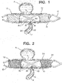
- FIG. 1 schematically illustrates a tubular, stent-like device 10 fabricated according to one technique of the present invention implanted in a parent vessel PV with an upper aneurysm A and a lower perforator vessel P.
- Device 10 is substantially tubular and has structure such as metallic struts 12 defining relatively large openings 13 and supporting a frangible cover material 14 which includes a film-like substance that is capable of rupturing wherever a preselected differential pressure is achieved.
- Frangible material 14 is shown intact along the entire exterior of struts 12, including across aneurysm neck N, except where ruptured by differential pressure with resulting film flaps 16 and 18 slightly extending into the ostium of perforator vessel P. Penetrating fluid flow from parent vessel PV into perforator vessel P is illustrated by arrows 20, 22 and 24.
- frangible cover material 14 disrupts flow which would otherwise occur into aneurysm A and thereby enables a thrombus to form within aneurysm A.
- frangible cover material 14 also enables blood to flow into perforator vessel P to continue feeding downstream tissues supplied by that vessel to minimize ischemia within those downstream tissues.
- frangible cover material 14 provides a flow barrier at neck N for at least eight-to-twelve weeks to allow endothelial growth over device 10.
- Device 10 can be either self-expanding or balloon expanded, with supporting scaffold-like structure 12 made by any of several typical stent fabrication methods.
- the struts 12 themselves are solid, typically metal, and do not change behavior according to the distinguishing feature of differential pressure across either an aneurysm neck or the ostium of a branching vessel.
- the struts 12 serve as a self-expanding scaffold made by laser-cutting a pattern of struts into a nitinol (NiTi) tube.
- NiTi nitinol
- the primary purposes of this structural component are to facilitate delivery of a film or other frangible cover material 14 to the target vessel, and to hold cover material 14 in apposition to the vessel wall once deployed. If the covering 14 is structurally sufficient to enable delivery and to hold position in the artery on its own, this scaffold 12 may not be needed.
- the open areas 13 within the scaffold 12 are subsequently covered by a film 14 which does respond according to the level of differential pressure felt across its wall thickness.
- a film 14 which does respond according to the level of differential pressure felt across its wall thickness.
- This film 14 can be made from any number of substances, as long as it has the minimum characteristics of biocompatibility and frangibility in the presence of a preselected, sufficient differential pressure.
- Suitable biocompatible compositions for frangible material 14 include films or matrices of cellulose, alginate, cross-linked gels, and very thin polymer films of materials such as urethane and/or poly-glycolic acid.
- the film 14 need not be erodible or bioabsorbable since it is the action of rupture in the presence of sufficient differential pressure that creates the permanent, localized modification of increased flow across its wall-thickness.
- the film 14 need not be erodible or bioabsorbable since it is the action of rupture in the presence of sufficient differential pressure that creates the permanent, localized modification of increased flow across its wall-thickness.
- microscopic pores or other openings could be formed in the film 14 having average diameters such as described for other embodiments below, it is acceptable for the film 14 to be a continuous sheet of material because the action of rupture increases flow where needed, as sensed by sufficient differential pressure to cause the rupture.
- the thickness of the film layer is determined by its desired rupture strength, but should not occupy a significant amount of cross-sectional area in the artery in order to minimize interference with normal fluid flow through the parent vessel. Less than five percent area occupation is desired.
- the thickness of the film is selected to achieve a desired frangibility at a minimum differential pressure within an acute time period to minimize ischemia downstream of the perforator vessel.
- the acute time period is preferably within a period of less than ten minutes, more preferably less than five minutes, in a majority of patients under typical conditions, that is, not including hypothermic or artificially depressed blood pressure conditions.
- the rupture strength should be adjusted so that the film is strong enough to survive delivery and placement within the target artery, but weak enough to rupture in the presence of the persistent, net-positive differential pressure across the ostium of small branching vessels. Desirable rupture strengths are expected to be in the range of 1 to 50 mmHg differential pressure.
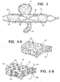
- An alternative tubular device 30, FIG. 2 has struts 32 which are similar to struts 12, FIG. 1 , and define relatively large openings 33, FIG. 2 .
- Device 30 further includes frangible material 34 which is formed from very thin fibers 35 in this construction that establish a porous mesh or matte outer layer.
- Frangible material 34 has a density sufficient to disrupt normal fluid flow at neck N to create stasis within aneurysm A to enable thrombi to form therein, yet a sufficient number of the fibers 35 part or separate to form opening 36 at the ostium of perforator vessel P when a threshold pressure differential is exceeded to enable blood to flow as illustrated by arrows 40 and 41.
- these fibers 35 are applied via "electro-spinning", where a liquefied polymer such as polyvinylidene fluoride (PVDF) exiting a dispenser tip has a voltage applied to it, producing a very fine strand having an average strand thickness or diameter of one nanometer up to about ten microns.
- PVDF polyvinylidene fluoride
- a number of controls over the construction of the fiber layer can be manipulated, such as the thickness of individual strands, the total number of strands applied, the angle at which the strand lays on the tubular scaffold, and the angles between strands which cross each other.
- electro-spinning techniques can be utilized, such as those described by Norton in U.S. Patent No. 2,048,651 .
- the resulting characteristics of the fiber layer as manufactured, before implantation include percentage area covered, average pore or opening size, total wall thickness, and hydraulic permeability, which provides a gross measurement of the volumetric flow rate of a certain liquid across the layer, in this case blood.
- the overall layer thickness of material 34 is about 10 microns to about 500 microns, more preferably 30 microns to 200 microns.
- the average opening diameter between fibers is preferably at least 10 microns before implantation in a patient. Average openings of about 10 microns permit a small quantity of whole blood, including red blood cells, to pass through the sidewalls of device 30 to provide some nourishment to surrounding tissues, while initially providing a substantial barrier to flow through material 34. As one or more fibers rupture in the presence of sufficient differential pressure such as at the ostium of the perforator vessel P, opening 36 is preferably formed to be from 50 to 500 microns, more typically 100 to 300 microns in diameter.
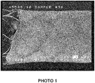
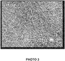
- One construction of device 30 is shown in PHOTOS 1-4 as scanning electron microscope images of successively smaller portions of the electro-spun fibers of device 30 at increasing magnifications of X15, X50, X200 and X2000, respectively.
- the left-hand side of PHOTO 1 shows fibers removed to expose the metallic struts which underlie and support the fibers, the struts defining large openings greater than one mm in this construction.
- a horizontal white bar illustrates a length of one mm to provide an indication of scale.
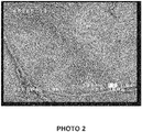
- PHOTO 2 is an enlargement of the outer fiber mat layer approximately in the center of PHOTO 1.
- a short horizontal white bar shows a length of 100 microns.
- PHOTO 3 is a further enlargement showing a longer white bar also having a length of 100 microns and revealing the three-dimensional nature of the fiber mat.
- PHOTO 4 clearly shows the porosity of the fiber mat, with a horizontal white bar of 10 microns for scale.
- the mechanism by which a sufficient number of these fibers "part" or separate in the presence of sufficient differential pressure is primarily that individual fibers will break, that is, rupture, in the localized areas of higher fluid flow.
- a mixture of biologically durable and degradable materials are utilized for the fibers.
- the local differential pressure is net positive and causes a persistent flow through the wall thickness of the layer.
- These broken fibers in the region of the layer covering the ostium of a branching vessel serve to increase the blood flow to that branching vessel preferentially compared to the region covering the aneurysm neck.
- the fibers 35 should be adjusted such that the fibers 35 break in areas with differential pressure preselected to be a threshold rupture pressure between 1 and 50 mmHg.
- the thickness of the fiber layer is determined by its rupture strength, but should not occupy a significant amount of cross-sectional area in the artery. Less than five percent area occupation is desired.
- a sufficient number of fibers break or erode within an acute time period, to minimize ischemia downstream of the perforator vessel, that is preferably within a period of less than ten minutes, more preferably less than five minutes, in a majority of patients under typical conditions, that is, not including hypothermic or artificially depressed blood pressure conditions.
- Tubular device 50 is yet another embodiment of the parent invention constructed with struts 52 arranged as a scaffold to define open areas or cells 53.
- This scaffold 52 can be either self-expanding or balloon expanded, made by any of several typical fabrication methods.
- the scaffold 52 is then covered according to one technique according to the present invention with a layer 54 that has very fine pores 55 and allows a limited amount of flow across its wall thickness in the presence of a net positive differential pressure.
- This layer 54 can be constructed by many methods, for example foaming, lyophilization, gaseous extraction, etching, firing, or deposition. A presently preferred method is described below in relation to FIGS. 5-7 .
- the material of layer 54 can be any biocompatible material that is subject to erosion due to fluid flow and/or erosion due to bioabsorption including consumption by live cells.
- polycaprolactone (PCL) is deposited in a somewhat sparse matrix such that it is porous as a bulk material.
- Other potential materials include polylactic acid (PLA), polyglycolic acid (PGA), polysaccharides, colloidal compounds, and some lipid products.
- a structure 60 of a durable, non-erodible, non-bioabsorbable material is first constructed.
- This flexible, elastic structure such as a solidified urethane foam or expanded polytetrafluoroethylene (PTFE)
- PTFE polytetrafluoroethylene
- structure 60 which may be reinforced with metal struts, establishes a maximum porosity for a device according to the present invention.
- Pores 62 are shown in cross-section with relatively straight passages, such as passage 72, for simplicity of illustration, in many constructions the passages are more complex and convoluted. Pores 62 are preferably formed to be from 50 to 500 microns in average diameter, more typically 100 to 300 microns in average diameter, as measured from scanning electron microscope images along a plane substantially parallel to the surface of structure material 60.
- a second substance 64 that is erodible is interstitially combined with the structure 60 to form a device 66, FIG. 4B .
- the second material 64 such as PCL or other materials listed above, preferably is deposited as particles or a microporous foam such that the material 64 has a desired level of porosity itself, that is, it is not an impermeable bulk material.
- material 64 defines openings having an average diameter of preferably at least 10 microns before implantation in a patient.
- Average openings of about 10 microns permit a small quantity of whole blood, including red blood cells, to pass through the sidewalls of device 66, as indicated by internal flow arrow 68 entering into passage 72 and external flow arrow 70 emerging from passage 72, to provide some nourishment to surrounding tissues, while initially providing a substantial barrier to flow through device 66.
- the persistent, penetrating flow through the wall of the combined layer will cause the second material 64 to respond by preferentially eroding, typically including biodegrading, more rapidly in one or more pores 62.
- the first purpose of the structure material 60 is to impose an upper limit on the increase in porosity, and therefore flow, to that of the structure 60 itself after all of the second material 64 has been removed. Its second purpose is to intensify the erosion, typically including biodegradation, of the second material 64 by concentrating the differential pressure provided by the branching vessel into a smaller porous area. This will improve the preferential nature by which the combined layer of device 66 will erode above branching vessels more quickly than in the general body of the device, including above an aneurysm neck.
- a presently preferred method for fabricating a frangible layer utilizes spray phase separation established by at least two spray devices.
- a spray system 100 includes a spray apparatus 101 with a first spray device 102 having an adjustable nozzle 104, a nozzle opening adjustment knob 106, and a flow control knob 108.
- a second spray device 110 has an adjustable nozzle 112, a nozzle opening adjustment knob 114, and a flow control knob 116.
- One full turn or rotation of flow control knob 108 or knob 116 is referred to as a revolution or "rev”.
- Spray devices 102 and 110 are mounted on a bracket 120 which, in some constructions, includes a carriage for spray apparatus 101 movable in a direction such as indicated by arrow 122.
- nozzles 104 and 112 are adjusted to create spray patterns 130 and 132, respectively, which overlap at collection region 134 on a cylindrical mandrel 140.
- mandrel 140 is moved in a direction such as represented by arrow 142.
- Nozzles 104 and 112 are positioned at a pre-selected distance PD and WD, respectively, from collection region 134.
- Suitable spray devices include AOM Asturo 878 WB Mini HVLP spray guns available from Asturo Spray Equipment, Rio Rancho, New Mexico.
- Presently preferred ranges of settings for spray system 100 include those shown in Table I: Parameter Low Setting High Setting Relative Translation Speed 11 cm/sec 33 cm/sec Distance 25 cm 33 cm Polymer Nozzle Diameter 0.8mm 1.2mm Non-Solvent Nozzle Diameter 0.8mm 1.2mm Polymer Flow 1 rev 2 rev Non-Solvent Flow 0.25 rev 1 rev
- the parameters shown in Table I are presently preferred for delivering a first polymer solution of polycaprolactone and polyurethane, preferably in a blend ratio of 80:20 to 50:50, through first spray device 102 and for delivering water as the non-solvent through second spray device 110.
- mandrel 140 is rotated about its longitudinal axis at speeds of 600 revolutions per minute to form a tubular porous membrane. This process preferably is conducted at standard temperature and pressure, with relative humidity preferably held to less than twenty percent.
- FIG. 6 is a flow chart outlining steps for operating system 100, FIG. 5 .
- the effective opening diameter of polymer nozzle 104 is set, step 150, and a flow rate for the polymer solution is selected, step 152.
- the effective opening diameter of non-solvent nozzle 112 is set, step 154, and a flow rate for the non-solvent solution is selected, step 152.
- the relative translation speed between the spray apparatus 101 and the mandrel 120 is selected, step 158, and spray distance PD and WD is set, step 160.
- System 100 is then operated at the pre-selected parameters to fabricate a porous membrane, step 162.
- FIG. 7 is a graph showing degradation of membranes formed according to the present invention with pure PCL in varying lipase concentrations. Percentage mass remaining is shown in the Y-axis and the number of days at which measurements were taken is shown on the X-axis. The immersion solution was changed every three days, and results are shown for three samples at each concentration.
- Curve 170 shows straight-line segments connecting points over time, with exponential function fit curve 172, for lipase concentrations of 0.95 mg/mL.
- curves 174 and 176 show mass remaining over time for lipase concentrations of 0.095 mg/mL and 0.0095 mg/mL lipase, respectively. Curves 174 and 176 are best approximated with cubic functions instead of exponential functions. Also shown is a single overlapping curve 178 for lipase concentrations 0.00095 and 0.000095 mg/mL lipase, respectively.
Landscapes
- Health & Medical Sciences (AREA)
- Surgery (AREA)
- Life Sciences & Earth Sciences (AREA)
- Heart & Thoracic Surgery (AREA)
- Molecular Biology (AREA)
- Vascular Medicine (AREA)
- Engineering & Computer Science (AREA)
- Biomedical Technology (AREA)
- Reproductive Health (AREA)
- Medical Informatics (AREA)
- Nuclear Medicine, Radiotherapy & Molecular Imaging (AREA)
- Animal Behavior & Ethology (AREA)
- General Health & Medical Sciences (AREA)
- Public Health (AREA)
- Veterinary Medicine (AREA)
- Prostheses (AREA)
- Media Introduction/Drainage Providing Device (AREA)
- Surgical Instruments (AREA)
- Materials For Medical Uses (AREA)
Claims (17)
- Procédé de fabrication d'un matériau frangible (14) pour un dispositif d'occlusion approprié pour un traitement endovasculaire d'un anévrisme dans une région d'un vaisseau parent dans un patient, comprenant les étapes suivantes:sélectionner un premier dispositif de pulvérisation (102) comportant une première ouverture de buse réglable et une première commande d'écoulement réglable;sélectionner un second dispositif de pulvérisation (110) comportant une seconde ouverture de buse réglable et une seconde commande d'écoulement réglable;sélectionner pour la première commande d'écoulement une position d'une unité à deux unités;sélectionner pour la seconde commande d'écoulement une position de 0,25 unité à une unité;agencer les premier et second dispositifs de pulvérisation (102, 110) de manière à distribuer des gouttelettes d'un premier liquide comprenant au moins un polymère biocompatible à travers le premier dispositif de pulvérisation et à distribuer des gouttelettes d'un second liquide comprenant un non-solvant pour le polymère à travers le second dispositif de pulvérisation dans un motif de pulvérisation à chevauchement sur un substrat à une distance comprise entre 25 cm et 35 cm;sélectionner une vitesse de transition relative de 11 cm/sec à 33 cm/sec entre (i) les premier et second dispositifs de pulvérisation et (ii) le substrat; etpulvériser le polymère et le non-solvant sur le substrat afin d'amener le polymère biocompatible à se dissocier de la solution de manière à former le matériau frangible (14) comme une membrane poreuse.
- Procédé selon la revendication 1, dans lequel le substrat est un mandrin (140).
- Procédé selon la revendication 1, dans lequel ledit au moins un polymère est le polycaprolactone.
- Procédé selon la revendication 3, dans lequel le premier liquide comprend en outre du polyuréthane.
- Procédé selon la revendication 1, comprenant en outre les étapes suivantes:régler la première ouverture de buse réglable à un diamètre compris entre 0,8 mm à 1,2 mm; etrégler la seconde ouverture de buse réglable à un diamètre compris entre 0,8 mm à 1,2 mm avant de sélectionner la première position de commande d'écoulement et la seconde position de commande d'écoulement,dans lequel le premier liquide comprend en outre au moins un polymère biodégradable.
- Procédé selon la revendication 1 ou la revendication 5, dans lequel le substrat est un mandrin sensiblement cylindrique (140).
- Procédé selon la revendication 6 lorsqu'elle dépend de la revendication 5, dans lequel ledit au moins un polymère biodégradable est le polycaprolactone.
- Procédé selon la revendication 7, dans lequel ledit au moins un polymère biocompatible est le polyuréthane.
- Procédé selon la revendication 1 ou la revendication 5, dans lequel le matériau frangible (14), lors de son implantation dans le vaisseau parent, fournit initialement une barrière substantielle à l'écoulement à travers le matériau frangible et est capable d'une érosion localisée, en présence d'un différentiel de pression survenant à un ostium d'un vaisseau perforant qui communique avec le vaisseau parent, à l'intérieur d'une période de temps critique afin de minimise une ischémie en aval du vaisseau perforant.
- Procédé selon la revendication 9, comprenant en outre, avant l'implantation, le placement du matériau frangible (14) sur une structure présentant une porosité fixe et présentant des dimensions appropriées pour une insertion dans le système vasculaire du patient pour atteindre la région de l'anévrisme dans le vaisseau parent.
- Procédé selon la revendication 10, dans lequel la structure comprend des entretoises métalliques.
- Procédé selon la revendication 9, dans lequel au moins une quantité substantielle de l'aire de surface du matériau frangible (14) définit des ouvertures d'au moins 10 microns de diamètre avant l'implantation dans le patient.
- Procédé selon la revendication 9, dans lequel le matériau frangible (14) présente une épaisseur comprise dans la gamme de 10 microns à 500 microns avant l'implantation dans le patient.
- Procédé selon la revendication 9, dans lequel le matériau frangible (14) est capable de réagir à un différentiel de pression équivalent à 0,1 kPa à 6,7 kPa (un à cinquante mm Hg).
- Procédé selon la revendication 9, dans lequel la période de temps critique est inférieure à dix minutes.
- Procédé selon la revendication 5, dans lequel le second liquide comprend l'eau comme non-solvant.
- Dispositif d'occlusion formé par le procédé selon la revendication 10.
Applications Claiming Priority (1)
| Application Number | Priority Date | Filing Date | Title |
|---|---|---|---|
| US13/796,415 US20130190805A1 (en) | 2011-03-31 | 2013-03-12 | Method of fabricating modifiable occlusion device |
Publications (2)
| Publication Number | Publication Date |
|---|---|
| EP2777543A1 EP2777543A1 (fr) | 2014-09-17 |
| EP2777543B1 true EP2777543B1 (fr) | 2017-11-29 |
Family
ID=50276939
Family Applications (1)
| Application Number | Title | Priority Date | Filing Date |
|---|---|---|---|
| EP14158741.0A Active EP2777543B1 (fr) | 2013-03-12 | 2014-03-11 | Procédé de fabrication de dispositif d'occlusion modifiable |
Country Status (9)
| Country | Link |
|---|---|
| EP (1) | EP2777543B1 (fr) |
| JP (1) | JP6373608B2 (fr) |
| KR (1) | KR102273599B1 (fr) |
| CN (1) | CN104068905B (fr) |
| AU (1) | AU2014201043B2 (fr) |
| BR (1) | BR102014005731A2 (fr) |
| CA (1) | CA2843941A1 (fr) |
| DK (1) | DK2777543T3 (fr) |
| IN (1) | IN2014DE00464A (fr) |
Cited By (1)
| Publication number | Priority date | Publication date | Assignee | Title |
|---|---|---|---|---|
| KR102232440B1 (ko) | 2013-03-13 | 2021-03-26 | 디퍼이 신테스 프로덕츠, 인코포레이티드 | 개선된 변경 가능한 폐색 장치 |
Families Citing this family (5)
| Publication number | Priority date | Publication date | Assignee | Title |
|---|---|---|---|---|
| EP2519161B1 (fr) | 2009-12-30 | 2020-04-29 | Vivasure Medical Limited | Système de fermeture |
| WO2016096932A1 (fr) | 2014-12-15 | 2016-06-23 | Vivasure Medical Limited | Appareil de fermeture avec élément scellable flexible et élément de support flexible |
| US11141142B2 (en) | 2014-12-15 | 2021-10-12 | Vivasure Medical Limited | Implantable sealable member with mesh layer |
| WO2017100221A1 (fr) * | 2015-12-07 | 2017-06-15 | Sano V Pte Ltd | Dispositifs et procédés pour un remodelage sensible à la pression de vaisseaux sanguins |
| WO2017102941A1 (fr) | 2015-12-15 | 2017-06-22 | Vivasure Medical Limited | Appareil de fermeture d'artériotomie avec patin rainure pour distribution avantageuse de compression |
Family Cites Families (19)
| Publication number | Priority date | Publication date | Assignee | Title |
|---|---|---|---|---|
| US692631A (en) | 1899-10-06 | 1902-02-04 | Charles S Farquhar | Apparatus for electrically dispersing fluids. |
| US705691A (en) | 1900-02-20 | 1902-07-29 | William James Morton | Method of dispersing fluids. |
| FR707191A (fr) | 1929-12-07 | 1931-07-03 | Ver Fur Chemische Ind Ag | Procédé pour fabriquer des fils artificiels |
| US2048651A (en) * | 1933-06-23 | 1936-07-21 | Massachusetts Inst Technology | Method of and apparatus for producing fibrous or filamentary material |
| US2349950A (en) | 1937-08-18 | 1944-05-30 | Formhals Anton | Method and apparatus for spinning |
| US5229045A (en) * | 1991-09-18 | 1993-07-20 | Kontron Instruments Inc. | Process for making porous membranes |
| US5938697A (en) * | 1998-03-04 | 1999-08-17 | Scimed Life Systems, Inc. | Stent having variable properties |
| US6187036B1 (en) | 1998-12-11 | 2001-02-13 | Endologix, Inc. | Endoluminal vascular prosthesis |
| US7270675B2 (en) * | 2002-05-10 | 2007-09-18 | Cordis Corporation | Method of forming a tubular membrane on a structural frame |
| US7335265B1 (en) | 2002-10-08 | 2008-02-26 | Advanced Cardiovascular Systems Inc. | Apparatus and method for coating stents |
| EP1431019B1 (fr) * | 2002-12-17 | 2007-03-07 | Integrated Biomaterial & Cell Technologies S.R.L. | Dispositif et son utilisation pour la fabrication de membranes poreuses pour utilisation médicale |
| US7763011B2 (en) * | 2003-12-22 | 2010-07-27 | Boston Scientific Scimed, Inc. | Variable density braid stent |
| US7156871B2 (en) | 2004-10-28 | 2007-01-02 | Cordis Neurovascular, Inc. | Expandable stent having a stabilized portion |
| EP2004101A2 (fr) | 2006-04-07 | 2008-12-24 | Penumbra, Inc. | Système et méthode d'occlusion d'anévrisme |
| US9474833B2 (en) | 2006-12-18 | 2016-10-25 | Cook Medical Technologies Llc | Stent graft with releasable therapeutic agent and soluble coating |
| US20100274276A1 (en) * | 2009-04-22 | 2010-10-28 | Ricky Chow | Aneurysm treatment system, device and method |
| US9554888B2 (en) * | 2010-04-20 | 2017-01-31 | University Of Utah Research Foundation | Phase separation sprayed scaffold |
| US8535590B2 (en) * | 2011-01-12 | 2013-09-17 | Cook Medical Technologies Llc | Spray system and method of making phase separated polymer membrane structures |
| US20120253377A1 (en) * | 2011-03-31 | 2012-10-04 | Codman & Shurtleff, Inc. | Modifiable occlusion device |
-
2014
- 2014-02-18 IN IN464DE2014 patent/IN2014DE00464A/en unknown
- 2014-02-26 CA CA2843941A patent/CA2843941A1/fr not_active Abandoned
- 2014-02-27 AU AU2014201043A patent/AU2014201043B2/en not_active Ceased
- 2014-03-07 KR KR1020140026863A patent/KR102273599B1/ko active IP Right Grant
- 2014-03-11 DK DK14158741.0T patent/DK2777543T3/da active
- 2014-03-11 JP JP2014047330A patent/JP6373608B2/ja active Active
- 2014-03-11 EP EP14158741.0A patent/EP2777543B1/fr active Active
- 2014-03-12 BR BRBR102014005731-5A patent/BR102014005731A2/pt not_active Application Discontinuation
- 2014-03-12 CN CN201410088950.4A patent/CN104068905B/zh active Active
Non-Patent Citations (1)
| Title |
|---|
| None * |
Cited By (1)
| Publication number | Priority date | Publication date | Assignee | Title |
|---|---|---|---|---|
| KR102232440B1 (ko) | 2013-03-13 | 2021-03-26 | 디퍼이 신테스 프로덕츠, 인코포레이티드 | 개선된 변경 가능한 폐색 장치 |
Also Published As
| Publication number | Publication date |
|---|---|
| JP2014171899A (ja) | 2014-09-22 |
| AU2014201043B2 (en) | 2018-11-08 |
| KR102273599B1 (ko) | 2021-07-07 |
| EP2777543A1 (fr) | 2014-09-17 |
| DK2777543T3 (da) | 2018-01-29 |
| CN104068905B (zh) | 2018-07-03 |
| AU2014201043A1 (en) | 2014-10-02 |
| KR20140111963A (ko) | 2014-09-22 |
| CN104068905A (zh) | 2014-10-01 |
| BR102014005731A2 (pt) | 2015-01-06 |
| JP6373608B2 (ja) | 2018-08-15 |
| IN2014DE00464A (fr) | 2015-06-12 |
| CA2843941A1 (fr) | 2014-09-12 |
Similar Documents
| Publication | Publication Date | Title |
|---|---|---|
| EP2777543B1 (fr) | Procédé de fabrication de dispositif d'occlusion modifiable | |
| CA2773163C (fr) | Dispositif d'occlusion modifiable | |
| US20130204288A1 (en) | Modifiable occlusion device | |
| US8357180B2 (en) | Thin film metallic device for plugging aneurysms or vessels | |
| US7811300B2 (en) | Thin film devices for temporary or permanent occlusion of a vessel | |
| JP6657281B2 (ja) | 改善された変化可能な閉塞装置 | |
| JP2013539398A (ja) | 血管の開孔又は窪みを閉じるためのデバイス | |
| AU2016374360B2 (en) | Implant | |
| US20130190805A1 (en) | Method of fabricating modifiable occlusion device | |
| CN116568242A (zh) | 用于治疗动脉瘤的医用植入物 | |
| JP2019505347A (ja) | ステント留置術用繊維管状導管 | |
| EP2575678B1 (fr) | Dispositif pour placement dans un organe creux, en particulier pour maintenir ouvert ledit organe creux et procédé pour produire un tel dispositif |
Legal Events
| Date | Code | Title | Description |
|---|---|---|---|
| 17P | Request for examination filed |
Effective date: 20140311 |
|
| AK | Designated contracting states |
Kind code of ref document: A1 Designated state(s): AL AT BE BG CH CY CZ DE DK EE ES FI FR GB GR HR HU IE IS IT LI LT LU LV MC MK MT NL NO PL PT RO RS SE SI SK SM TR |
|
| AX | Request for extension of the european patent |
Extension state: BA ME |
|
| PUAI | Public reference made under article 153(3) epc to a published international application that has entered the european phase |
Free format text: ORIGINAL CODE: 0009012 |
|
| R17P | Request for examination filed (corrected) |
Effective date: 20150213 |
|
| RBV | Designated contracting states (corrected) |
Designated state(s): AL AT BE BG CH CY CZ DE DK EE ES FI FR GB GR HR HU IE IS IT LI LT LU LV MC MK MT NL NO PL PT RO RS SE SI SK SM TR |
|
| GRAP | Despatch of communication of intention to grant a patent |
Free format text: ORIGINAL CODE: EPIDOSNIGR1 |
|
| INTG | Intention to grant announced |
Effective date: 20170208 |
|
| RIN1 | Information on inventor provided before grant (corrected) |
Inventor name: GEEST, DR. JONATHAN VANDE Inventor name: SLAZAS, ROBERT |
|
| GRAJ | Information related to disapproval of communication of intention to grant by the applicant or resumption of examination proceedings by the epo deleted |
Free format text: ORIGINAL CODE: EPIDOSDIGR1 |
|
| GRAP | Despatch of communication of intention to grant a patent |
Free format text: ORIGINAL CODE: EPIDOSNIGR1 |
|
| INTC | Intention to grant announced (deleted) | ||
| INTG | Intention to grant announced |
Effective date: 20170612 |
|
| GRAS | Grant fee paid |
Free format text: ORIGINAL CODE: EPIDOSNIGR3 |
|
| GRAA | (expected) grant |
Free format text: ORIGINAL CODE: 0009210 |
|
| AK | Designated contracting states |
Kind code of ref document: B1 Designated state(s): AL AT BE BG CH CY CZ DE DK EE ES FI FR GB GR HR HU IE IS IT LI LT LU LV MC MK MT NL NO PL PT RO RS SE SI SK SM TR |
|
| REG | Reference to a national code |
Ref country code: CH Ref legal event code: EP Ref country code: CH Ref legal event code: NV Representative=s name: E. BLUM AND CO. AG PATENT- UND MARKENANWAELTE , CH |
|
| REG | Reference to a national code |
Ref country code: AT Ref legal event code: REF Ref document number: 949653 Country of ref document: AT Kind code of ref document: T Effective date: 20171215 |
|
| REG | Reference to a national code |
Ref country code: IE Ref legal event code: FG4D |
|
| REG | Reference to a national code |
Ref country code: DE Ref legal event code: R096 Ref document number: 602014017782 Country of ref document: DE |
|
| REG | Reference to a national code |
Ref country code: DK Ref legal event code: T3 Effective date: 20180122 |
|
| REG | Reference to a national code |
Ref country code: FR Ref legal event code: PLFP Year of fee payment: 5 |
|
| REG | Reference to a national code |
Ref country code: NL Ref legal event code: MP Effective date: 20171129 |
|
| REG | Reference to a national code |
Ref country code: LT Ref legal event code: MG4D |
|
| REG | Reference to a national code |
Ref country code: AT Ref legal event code: MK05 Ref document number: 949653 Country of ref document: AT Kind code of ref document: T Effective date: 20171129 |
|
| PG25 | Lapsed in a contracting state [announced via postgrant information from national office to epo] |
Ref country code: ES Free format text: LAPSE BECAUSE OF FAILURE TO SUBMIT A TRANSLATION OF THE DESCRIPTION OR TO PAY THE FEE WITHIN THE PRESCRIBED TIME-LIMIT Effective date: 20171129 Ref country code: NO Free format text: LAPSE BECAUSE OF FAILURE TO SUBMIT A TRANSLATION OF THE DESCRIPTION OR TO PAY THE FEE WITHIN THE PRESCRIBED TIME-LIMIT Effective date: 20180228 Ref country code: FI Free format text: LAPSE BECAUSE OF FAILURE TO SUBMIT A TRANSLATION OF THE DESCRIPTION OR TO PAY THE FEE WITHIN THE PRESCRIBED TIME-LIMIT Effective date: 20171129 Ref country code: SE Free format text: LAPSE BECAUSE OF FAILURE TO SUBMIT A TRANSLATION OF THE DESCRIPTION OR TO PAY THE FEE WITHIN THE PRESCRIBED TIME-LIMIT Effective date: 20171129 Ref country code: LT Free format text: LAPSE BECAUSE OF FAILURE TO SUBMIT A TRANSLATION OF THE DESCRIPTION OR TO PAY THE FEE WITHIN THE PRESCRIBED TIME-LIMIT Effective date: 20171129 |
|
| PG25 | Lapsed in a contracting state [announced via postgrant information from national office to epo] |
Ref country code: AT Free format text: LAPSE BECAUSE OF FAILURE TO SUBMIT A TRANSLATION OF THE DESCRIPTION OR TO PAY THE FEE WITHIN THE PRESCRIBED TIME-LIMIT Effective date: 20171129 Ref country code: LV Free format text: LAPSE BECAUSE OF FAILURE TO SUBMIT A TRANSLATION OF THE DESCRIPTION OR TO PAY THE FEE WITHIN THE PRESCRIBED TIME-LIMIT Effective date: 20171129 Ref country code: GR Free format text: LAPSE BECAUSE OF FAILURE TO SUBMIT A TRANSLATION OF THE DESCRIPTION OR TO PAY THE FEE WITHIN THE PRESCRIBED TIME-LIMIT Effective date: 20180301 Ref country code: RS Free format text: LAPSE BECAUSE OF FAILURE TO SUBMIT A TRANSLATION OF THE DESCRIPTION OR TO PAY THE FEE WITHIN THE PRESCRIBED TIME-LIMIT Effective date: 20171129 Ref country code: HR Free format text: LAPSE BECAUSE OF FAILURE TO SUBMIT A TRANSLATION OF THE DESCRIPTION OR TO PAY THE FEE WITHIN THE PRESCRIBED TIME-LIMIT Effective date: 20171129 Ref country code: BG Free format text: LAPSE BECAUSE OF FAILURE TO SUBMIT A TRANSLATION OF THE DESCRIPTION OR TO PAY THE FEE WITHIN THE PRESCRIBED TIME-LIMIT Effective date: 20180228 |
|
| PG25 | Lapsed in a contracting state [announced via postgrant information from national office to epo] |
Ref country code: NL Free format text: LAPSE BECAUSE OF FAILURE TO SUBMIT A TRANSLATION OF THE DESCRIPTION OR TO PAY THE FEE WITHIN THE PRESCRIBED TIME-LIMIT Effective date: 20171129 |
|
| PG25 | Lapsed in a contracting state [announced via postgrant information from national office to epo] |
Ref country code: CZ Free format text: LAPSE BECAUSE OF FAILURE TO SUBMIT A TRANSLATION OF THE DESCRIPTION OR TO PAY THE FEE WITHIN THE PRESCRIBED TIME-LIMIT Effective date: 20171129 Ref country code: SK Free format text: LAPSE BECAUSE OF FAILURE TO SUBMIT A TRANSLATION OF THE DESCRIPTION OR TO PAY THE FEE WITHIN THE PRESCRIBED TIME-LIMIT Effective date: 20171129 Ref country code: CY Free format text: LAPSE BECAUSE OF FAILURE TO SUBMIT A TRANSLATION OF THE DESCRIPTION OR TO PAY THE FEE WITHIN THE PRESCRIBED TIME-LIMIT Effective date: 20171129 Ref country code: EE Free format text: LAPSE BECAUSE OF FAILURE TO SUBMIT A TRANSLATION OF THE DESCRIPTION OR TO PAY THE FEE WITHIN THE PRESCRIBED TIME-LIMIT Effective date: 20171129 |
|
| REG | Reference to a national code |
Ref country code: DE Ref legal event code: R097 Ref document number: 602014017782 Country of ref document: DE |
|
| PG25 | Lapsed in a contracting state [announced via postgrant information from national office to epo] |
Ref country code: PL Free format text: LAPSE BECAUSE OF FAILURE TO SUBMIT A TRANSLATION OF THE DESCRIPTION OR TO PAY THE FEE WITHIN THE PRESCRIBED TIME-LIMIT Effective date: 20171129 Ref country code: RO Free format text: LAPSE BECAUSE OF FAILURE TO SUBMIT A TRANSLATION OF THE DESCRIPTION OR TO PAY THE FEE WITHIN THE PRESCRIBED TIME-LIMIT Effective date: 20171129 Ref country code: SM Free format text: LAPSE BECAUSE OF FAILURE TO SUBMIT A TRANSLATION OF THE DESCRIPTION OR TO PAY THE FEE WITHIN THE PRESCRIBED TIME-LIMIT Effective date: 20171129 |
|
| PLBE | No opposition filed within time limit |
Free format text: ORIGINAL CODE: 0009261 |
|
| STAA | Information on the status of an ep patent application or granted ep patent |
Free format text: STATUS: NO OPPOSITION FILED WITHIN TIME LIMIT |
|
| 26N | No opposition filed |
Effective date: 20180830 |
|
| PG25 | Lapsed in a contracting state [announced via postgrant information from national office to epo] |
Ref country code: SI Free format text: LAPSE BECAUSE OF FAILURE TO SUBMIT A TRANSLATION OF THE DESCRIPTION OR TO PAY THE FEE WITHIN THE PRESCRIBED TIME-LIMIT Effective date: 20171129 Ref country code: MC Free format text: LAPSE BECAUSE OF FAILURE TO SUBMIT A TRANSLATION OF THE DESCRIPTION OR TO PAY THE FEE WITHIN THE PRESCRIBED TIME-LIMIT Effective date: 20171129 |
|
| REG | Reference to a national code |
Ref country code: BE Ref legal event code: MM Effective date: 20180331 |
|
| REG | Reference to a national code |
Ref country code: IE Ref legal event code: MM4A |
|
| PG25 | Lapsed in a contracting state [announced via postgrant information from national office to epo] |
Ref country code: LU Free format text: LAPSE BECAUSE OF NON-PAYMENT OF DUE FEES Effective date: 20180311 |
|
| PG25 | Lapsed in a contracting state [announced via postgrant information from national office to epo] |
Ref country code: IE Free format text: LAPSE BECAUSE OF NON-PAYMENT OF DUE FEES Effective date: 20180311 |
|
| PG25 | Lapsed in a contracting state [announced via postgrant information from national office to epo] |
Ref country code: BE Free format text: LAPSE BECAUSE OF NON-PAYMENT OF DUE FEES Effective date: 20180331 |
|
| PG25 | Lapsed in a contracting state [announced via postgrant information from national office to epo] |
Ref country code: MT Free format text: LAPSE BECAUSE OF NON-PAYMENT OF DUE FEES Effective date: 20180311 |
|
| PG25 | Lapsed in a contracting state [announced via postgrant information from national office to epo] |
Ref country code: TR Free format text: LAPSE BECAUSE OF FAILURE TO SUBMIT A TRANSLATION OF THE DESCRIPTION OR TO PAY THE FEE WITHIN THE PRESCRIBED TIME-LIMIT Effective date: 20171129 |
|
| PGFP | Annual fee paid to national office [announced via postgrant information from national office to epo] |
Ref country code: DK Payment date: 20200310 Year of fee payment: 7 |
|
| PG25 | Lapsed in a contracting state [announced via postgrant information from national office to epo] |
Ref country code: PT Free format text: LAPSE BECAUSE OF FAILURE TO SUBMIT A TRANSLATION OF THE DESCRIPTION OR TO PAY THE FEE WITHIN THE PRESCRIBED TIME-LIMIT Effective date: 20171129 Ref country code: HU Free format text: LAPSE BECAUSE OF FAILURE TO SUBMIT A TRANSLATION OF THE DESCRIPTION OR TO PAY THE FEE WITHIN THE PRESCRIBED TIME-LIMIT; INVALID AB INITIO Effective date: 20140311 |
|
| PGFP | Annual fee paid to national office [announced via postgrant information from national office to epo] |
Ref country code: CH Payment date: 20200313 Year of fee payment: 7 |
|
| PG25 | Lapsed in a contracting state [announced via postgrant information from national office to epo] |
Ref country code: MK Free format text: LAPSE BECAUSE OF NON-PAYMENT OF DUE FEES Effective date: 20171129 |
|
| PG25 | Lapsed in a contracting state [announced via postgrant information from national office to epo] |
Ref country code: AL Free format text: LAPSE BECAUSE OF FAILURE TO SUBMIT A TRANSLATION OF THE DESCRIPTION OR TO PAY THE FEE WITHIN THE PRESCRIBED TIME-LIMIT Effective date: 20171129 Ref country code: IS Free format text: LAPSE BECAUSE OF FAILURE TO SUBMIT A TRANSLATION OF THE DESCRIPTION OR TO PAY THE FEE WITHIN THE PRESCRIBED TIME-LIMIT Effective date: 20180329 |
|
| REG | Reference to a national code |
Ref country code: CH Ref legal event code: PL |
|
| REG | Reference to a national code |
Ref country code: DK Ref legal event code: EBP Effective date: 20210331 |
|
| PG25 | Lapsed in a contracting state [announced via postgrant information from national office to epo] |
Ref country code: LI Free format text: LAPSE BECAUSE OF NON-PAYMENT OF DUE FEES Effective date: 20210331 Ref country code: CH Free format text: LAPSE BECAUSE OF NON-PAYMENT OF DUE FEES Effective date: 20210331 |
|
| PG25 | Lapsed in a contracting state [announced via postgrant information from national office to epo] |
Ref country code: DK Free format text: LAPSE BECAUSE OF NON-PAYMENT OF DUE FEES Effective date: 20210331 |
|
| PGFP | Annual fee paid to national office [announced via postgrant information from national office to epo] |
Ref country code: GB Payment date: 20220203 Year of fee payment: 9 |
|
| GBPC | Gb: european patent ceased through non-payment of renewal fee |
Effective date: 20230311 |
|
| PG25 | Lapsed in a contracting state [announced via postgrant information from national office to epo] |
Ref country code: GB Free format text: LAPSE BECAUSE OF NON-PAYMENT OF DUE FEES Effective date: 20230311 |
|
| PG25 | Lapsed in a contracting state [announced via postgrant information from national office to epo] |
Ref country code: GB Free format text: LAPSE BECAUSE OF NON-PAYMENT OF DUE FEES Effective date: 20230311 |
|
| PGFP | Annual fee paid to national office [announced via postgrant information from national office to epo] |
Ref country code: DE Payment date: 20240130 Year of fee payment: 11 |
|
| PGFP | Annual fee paid to national office [announced via postgrant information from national office to epo] |
Ref country code: IT Payment date: 20240212 Year of fee payment: 11 Ref country code: FR Payment date: 20240213 Year of fee payment: 11 |