EP2777450B1 - Food preparation appliance for steam cooking and food processing - Google Patents
Food preparation appliance for steam cooking and food processing Download PDFInfo
- Publication number
- EP2777450B1 EP2777450B1 EP14157804.7A EP14157804A EP2777450B1 EP 2777450 B1 EP2777450 B1 EP 2777450B1 EP 14157804 A EP14157804 A EP 14157804A EP 2777450 B1 EP2777450 B1 EP 2777450B1
- Authority
- EP
- European Patent Office
- Prior art keywords
- bowl
- steam
- food
- interior space
- appliance
- Prior art date
- Legal status (The legal status is an assumption and is not a legal conclusion. Google has not performed a legal analysis and makes no representation as to the accuracy of the status listed.)
- Not-in-force
Links
Images


Classifications
-
- A—HUMAN NECESSITIES
- A47—FURNITURE; DOMESTIC ARTICLES OR APPLIANCES; COFFEE MILLS; SPICE MILLS; SUCTION CLEANERS IN GENERAL
- A47J—KITCHEN EQUIPMENT; COFFEE MILLS; SPICE MILLS; APPARATUS FOR MAKING BEVERAGES
- A47J27/00—Cooking-vessels
- A47J27/04—Cooking-vessels for cooking food in steam; Devices for extracting fruit juice by means of steam ; Vacuum cooking vessels
-
- A—HUMAN NECESSITIES
- A23—FOODS OR FOODSTUFFS; TREATMENT THEREOF, NOT COVERED BY OTHER CLASSES
- A23L—FOODS, FOODSTUFFS, OR NON-ALCOHOLIC BEVERAGES, NOT COVERED BY SUBCLASSES A21D OR A23B-A23J; THEIR PREPARATION OR TREATMENT, e.g. COOKING, MODIFICATION OF NUTRITIVE QUALITIES, PHYSICAL TREATMENT; PRESERVATION OF FOODS OR FOODSTUFFS, IN GENERAL
- A23L5/00—Preparation or treatment of foods or foodstuffs, in general; Food or foodstuffs obtained thereby; Materials therefor
- A23L5/10—General methods of cooking foods, e.g. by roasting or frying
- A23L5/13—General methods of cooking foods, e.g. by roasting or frying using water or steam
-
- A—HUMAN NECESSITIES
- A47—FURNITURE; DOMESTIC ARTICLES OR APPLIANCES; COFFEE MILLS; SPICE MILLS; SUCTION CLEANERS IN GENERAL
- A47J—KITCHEN EQUIPMENT; COFFEE MILLS; SPICE MILLS; APPARATUS FOR MAKING BEVERAGES
- A47J43/00—Implements for preparing or holding food, not provided for in other groups of this subclass
- A47J43/04—Machines for domestic use not covered elsewhere, e.g. for grinding, mixing, stirring, kneading, emulsifying, whipping or beating foodstuffs, e.g. power-driven
- A47J43/046—Machines for domestic use not covered elsewhere, e.g. for grinding, mixing, stirring, kneading, emulsifying, whipping or beating foodstuffs, e.g. power-driven with tools driven from the bottom side
-
- A—HUMAN NECESSITIES
- A47—FURNITURE; DOMESTIC ARTICLES OR APPLIANCES; COFFEE MILLS; SPICE MILLS; SUCTION CLEANERS IN GENERAL
- A47J—KITCHEN EQUIPMENT; COFFEE MILLS; SPICE MILLS; APPARATUS FOR MAKING BEVERAGES
- A47J27/00—Cooking-vessels
- A47J27/04—Cooking-vessels for cooking food in steam; Devices for extracting fruit juice by means of steam ; Vacuum cooking vessels
- A47J2027/043—Cooking-vessels for cooking food in steam; Devices for extracting fruit juice by means of steam ; Vacuum cooking vessels for cooking food in steam
Description
- The field of the disclosure relates generally to food preparation appliances, more particularly to a steam cooker appliance, and even more particularly to a combination food processor and steam cooker appliance.
- Food preparation appliances come in many different types and are used in numerous different ways to prepare food. For example, one common food preparation appliance is steamer, or steam cooker, in which food is cooked using high temperature steam. Commonly known steamers include a base, a water reservoir, a heater for heating the water to produce steam, and a closeable container in which the food is held during use. Steam is introduced into the container to heat the food. Once drawback of some steam cookers is that upon initially introducing steam into the container (with food therein), the cooler (e.g., room temperature) air in the container causes the steam to condense on the interior walls of the container, often resulting in excess moisture to build up in the container and on the ingredients. Accordingly, such devices typically require that the user drain excess liquid from the ingredients or move them to a separate container for processing, after being steamed. If the excess liquid is not drained, the processed ingredients can become soggy or otherwise have an undesirable consistency. To this end, some other steam cookers have containers in which the bottom is perforated (e.g., a steaming basket). As such, these steaming baskets do not allow a user to cook a meltable substance (e.g., chocolate or cheese) therein, because the substance will leak through the perforations in the basket as the substance melts.
- Another common type of food appliance includes a food processing device, which is typically used to process food ingredients from one form to another. For example, such devices are known for use in mixing/blending, processing, mashing chopping, slicing, dicing, mincing, grating or cutting food ingredients. Many food processors are electrically powered device that include a base housing an electric drive motor, and a container seatable on the base and having one or more processing implements (e.g., a blade) disposed in the container and operatively connectable to the drive motor. In use of the food processor, the container is placed and secured on the base and food is loaded into the container. The food processor is activated by a user to operate the motor, which operatively drives the processing implement to work the food in the desired manner. In some instances, the lid of the jar is configured with a chute open to the interior of the container to allow the user to add ingredients during operation of the food processor.
- While food processors may be used to process raw or uncooked foods, as well as cooked foods, food processors themselves are not used to cook the foods. As such, the user must remove uncooked food after processing and then subsequently cook the processed food (if cooking is desired), or food must be cooked outside of the container and then loaded into the container for processing.
- There is a need, therefore, for a steam cooker that remedies the above drawbacks associated with conventional steam cookers, as well as for a food processor that allows for steam cooking in the container of the food processor without having to remove food from the container and without having to remove the container from the base of the appliance to drain liquid from the food.
- A food preparation appliance, method of preparing food in a food preparation appliance and a bowl for use with a food preparation appliance, having the features of the preamble of claims 1, 8 and 12, is disclosed in
US-A-4574776 . - The present invention provides a food preparation appliance as recited in claim 1, a method of preparing food in a food preparation device as recited in claim 8 and a bowl for use with a food preparation device as claimed in claim 12.
-
-
Fig. 1 is a perspective view of one embodiment of a food preparation appliance in the form of a combination food processor and steam cooker. -
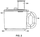
Fig. 2 is a side elevation of a container of the food preparation appliance ofFig. 1 . -
Fig. 3 is a vertical cross-section section of the container ofFig. 2 , with a drive system and food processing implements of the appliance omitted. -
Fig. 4 is a vertical cross-section similar toFig. 3 with the drive system and food processing implements assembled with the container, and with directional arrows indicating the flow of steam within the appliance. -
Fig. 5 is an expanded view of a portion ofFig. 4 . -
Fig. 6 is an exploded perspective view of the drive system and food processing implements of the appliance ofFig. 4 . -
Fig. 7 is an exploded side elevation of the drive system and food processing implements. -
Fig. 8 is a perspective of the drive system and food processing implements fully assembled. -
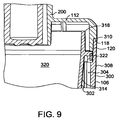
Fig. 9 is an expanded view of another portion ofFig. 4 . -
Fig. 10 is a perspective vertical cross-section of the container ofFig. 2 with the lid removed. -
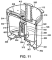
Fig. 11 is a perspective similar toFig. 10 but with the lid in place. - Referring now to the drawings, and in particular
Fig. 1 , one embodiment of a food preparation appliance is indicated generally at 100. The illustratedappliance 100 is in the form of a combination food processor and steam cooker. It is understood, however, that theappliance 100 may instead be solely in the form of a steam cooker and remain within the scope of this invention. It is also contemplated that theappliance 100 may be in the form of a steam cooker in combination with a food preparation device other than a food processor, or in addition to a food processor. Thefood preparation appliance 100 generally comprises abase 102 housing a drive motor (not shown) that includes a drive coupling (not shown) accessible from the top of the base. Asuitable control panel 104 including adisplay 114 andoperating switches 116 is disposed on thebase 102 of theappliance 100 for operating the appliance. Theappliance 100 further comprises acontainer 106 for containing food during processing and configured for seating on thebase 102 in releasable interlocking or interconnecting engagement therewith. Ahandle 108 is provided on the illustratedcontainer 106 for ease of gripping and manipulating the container. - The illustrated
appliance 100 also has areservoir 110 for containing a liquid, e.g., water, and a heating device (not shown) for sufficiently heating the liquid to generate steam. A cover member 112 (e.g., a lid) is provided for the container to close thecontainer 106 during operation. Thecover member 112 is suitably releasably held on thecontainer 106, such as in sealing engagement therewith, and includes achute 200 open to the interior of the container for introducing ingredients into the interior of container while the cover member is on the container. In some embodiments, thecontainer 106 andcover member 112 may include a safety device, such as a pressure activated switch (not shown) or the like, configured to prevent the drive motor in thebase 102 from being activated unless the cover member is securely closed on the container. Thecontainer 106, as illustrated inFig. 2 , also includes anannular skirt 202 or other suitable alignment structure to facilitate alignment of the container on thebase 102. For example, thebase 102 may include a channel, or depression (not shown) corresponding to theskirt 202 allowing for a user to more readily place thecontainer 106 on thebase 102 in the proper position and allow for a more stable seating of the container on the base. - With reference now to
Figs. 3 and4 , in one embodiment thecontainer 106 generally comprises anouter bowl 300 and aninner bowl 302. Theouter bowl 300 includes abottom 306, theannular skirt 202 depending from the bottom of the outer bowl, and aperipheral sidewall 308 extending up from the bottom of the outer bowl. Acentral portion 307 of thebottom 306 of theouter bowl 300 is inset (e.g., raised in the embodiment ofFig. 3 ) to accommodate a suitable drive coupling 420 (e.g., as illustrated inFig. 4 ) configured for driving connection with the drive coupling (not shown) of the drive motor (not shown) of thebase 102. Acentral opening 309 is disposed in thecentral portion 307 of thebottom 306 of the outer bowl to allow extension therethrough of a suitable drive member 422 (Fig. 4 ) extending up from thedrive coupling 420. As illustrated best inFig. 9 , theperipheral sidewall 308 of the outer bowl includes anupper rim 310 defining an opening to the interior of theouter bowl 300, and a shoulder 311 formed on the inner surface of the peripheral wall to support theinner bowl 302 within the outer bowl. - Referring back to
Figs. 3 and4 , theinner bowl 302 includes abottom 312 configured and arranged for opposed relationship with thebottom 306 of theouter bowl 300, and aperipheral side wall 314 extending up from thebottom 312 and configured and arranged for opposed relationship with theperipheral side wall 308 of the outer bowl. The inner surface of theinner bowl 302 defines the interior of thecontainer 106 in which food is processed (also broadly referred to as the food processing chamber). Theinner bowl 302 is suitably sized in height and transverse cross-section (e.g., diameter) for at least partial insertion within theouter bowl 300. More suitably, theinner bowl 302 is sized in height and transverse cross-section for disposition within theouter bowl 300 such that at least thebottom 312 of the inner bowl is spaced from thebottom 306 of the outer bowl to define agap 304 therebetween. In a more suitable embodiment, theperipheral side wall 314 of the inner bowl is also spaced from theperipheral side wall 308 of theouter bowl 300 so that thegap 304 further extends along at least a portion of the height of the outer bowl and more suitably along a substantial portion of the entire height of the outer bowl. - As illustrated best in
Fig. 3 , theinner bowl 302 further includes acentral column 316 extending up from thebottom 312 of the inner bowl. Thecolumn 316 is open at both ends (one end being at the bottom 312) of the inner bowl 302) to accommodate a portion of thedrive member 422 as well as a transmission member (Figs. 4 and5 ) that is operatively coupled to the drive member for driven rotation with the drive member in response to operation of the drive motor of thebase 102. Theperipheral side wall 314 of theinner bowl 302 has anupper rim 318 defining theinterior 320 of the inner bowl and hence the interior (i.e., food processing chamber) of thecontainer 106. As illustrated inFig. 9 , anannular flange 322 extends transversely outward from the outer surface of theperipheral sidewall 314 of theinner bowl 302 for seating on the shoulder 311 formed in the inner surface of theperipheral sidewall 308 of the outer bowl so that the inner bowl is releasably supported by the outer bowl with the desiredgap 304 between the inner and outer bowls. Contact between theannular flange 322 of the inner bowl and the shoulder 311 of theouter bowl 300 also generally closes thegap 304 between the inner and outer bowls. - Still referring to
Fig. 9 , thecover member 112 is suitably configured to sealingly engage at least theouter bowl 300 to close theinterior 320 of thecontainer 106 during operation of theappliance 100. For example, the illustratedcover member 112 has ashoulder 118 configured for seating on theupper rim 310 of the outer bowl. Aterminal segment 120 of the cover member extends downward from the shoulder for at least closely spaced relationship with the inner surface of the outer bowl adjacent theupper rim 310, and more suitably close contact relationship with the inner surface of the outer bowl adjacent the upper rim as illustrated inFig. 9 . While shown in the illustrated embodiments, a suitable sealing member (e.g., in the form of an O-ring, gasket or other suitable sealing member, may be used to further seal thecover member 112 on theouter bowl 300. It is also contemplated that thecover member 112 may alternatively, or additionally, contact and in some embodiments seal against theinner bowl 302 without departing from the scope of this invention. Thechute 200 extends through thecover member 112, thus allowing objects or ingredients to be inserted into thefood processing chamber 320 without removing thecover member 112. - With particular reference to
Figs. 4-8 , thedrive member 422 extends vertically up from thedrive coupling 420 and includes anannular shoulder 424. Thetransmission member 406 is generally tubular, having aninner channel 426 configured to receive thedrive member 422 therein. Abase 428 of thetransmission member 406 seats on theannular shoulder 424 to limit the extension of thedrive member 422 into theinner channel 426 of the transmission member. The transverse cross-section of theinner channel 426 is keyed to the transverse cross-section of thedrive member 422 above theshoulder 424 to drivingly connect thetransmission member 406 to the drive member for conjoint rotation therewith upon operation of the drive motor of theappliance 100. Thebase 428 of the transmission member defines ashoulder 430 the purpose of which is described later herein. - With continued reference to
Figs. 4-7 , a food processing implement 400 is disposed within theinner bowl 302 of thecontainer 106 and operatively connected to the transmission member 406 - and hence the drive motor - for rotation relative to the container. More particularly, the illustrated food processing implement 400 has anelongate hub 402 that is generally hollow along its length and has asidewall 432 sized in transverse cross-section for seating over and thus surrounding thecentral column 316 extending up from thebottom 312 of the inner bowl as seen best inFigs. 4 and5 . In the illustrated embodiment, the food processing implement 400 is in the form of a cutting implement having one ormore blade elements 600 extending transversely outward from the lower region of thehub 402 of the implement. It is understood that the implement 400 may have any number ofblades 600, and that the blades may be of any suitable configuration, without departing from within the scope of this invention. It is also understood that the implement 400 may be configured other than for cutting. For example, the food processing implement 400 may be a grater, shredder, kneader, strainer or the like. - An
elongate drive shaft 434 is formed integrally with theillustrated hub 402 and includes alower segment 436 extending axially within the hub and an upper segment extending axially upward of the hub. Thelower segment 436 has asidewall 440 defining aninner channel 442 configured for receiving thetransmission member 406 therein. The transverse cross-section of theinner channel 442 of the drive shaftlower segment 436 is keyed to the transverse cross-section of thetransmission member 406 to thereby operatively connect thehub 402 to the transmission member for driven rotation of the hub conjointly with the drive motor in theappliance base 102. The lower end of thelower segment 436 seats on theshoulder 430 of thetransmission member 406 to axially position thehub 402 relative to theinner bowl 302 of thecontainer 106. - In the illustrated embodiment, the
sidewall 440 of thelower segment 436 of thedrive shaft 434 is transversely spaced from thesidewall 432 of thehub 402 to accommodate thecolumn 316 therebetween. More particularly, as seen best inFig. 5 , the spacing therebetween is such that thesidewall 440 of thelower segment 436 of thedrive shaft 434 is transversely spaced from thecolumn 316 and thesidewall 432 of thehub 402 is transversely spaced from thecolumn 316 to define a continuous flow path for steam flowing from the interior to the exterior of the hub as described later herein. - In the illustrated embodiment, a second food processing implement 408 is operatively connected to the
upper segment 438 of the drive shaft 434 (e.g., in axially spaced relationship with the food processing implement 400) for conjoint rotation with the drive shaft and hence the other food processing implement. This second food processing implement 408 may be positioned closer to theupper rim 318 of theinner bowl 302 than the food processing implement 400, and may be the same type of food processing implement as the food processing implement 400, or a different type. For example the illustrated second food processing implement 408 is a slicing type of food processing implement. Also best illustrated inFigs. 10 and11 , analignment pin 410 seats within the upper end of thedrive 434 and extends axially into aseat 412 formed in thecover member 112 to facilitate and maintain axial alignment of the drive shaft (and hence the food processing implements 400, 408) in thecontainer 106. - Operation of the
appliance 100 will now be described with particular reference toFigs. 4 and5 . Initially, a user inserts one or more ingredients (not shown), such as food ingredients, into the interior space (i.e., the food processing chamber) 320 of the container (e.g., as defined by the interior space of the inner bowl 302). The food ingredients typically rest on thebottom 312 of theinner bowl 302. At this time, the user may begin a steam cooking operation by accessing the control panel 104 (Fig. 1 ), such as by using the one or more buttons or switches 116, to initiate a steaming operation. Once the steaming operation is initiated, a steam generating device 500 (e.g., heating device) within thebase 102 is activated to generate steam from the liquid (e.g., water) disposed in thereservoir 110. In other suitable embodiments, theheating device 500 may be disposed in whole or in part in thereservoir 110. The generated steam is directed into thecontainer 106 by way of asuitable conduit 502. More particularly, in the illustrated embodiment ofFig. 4 steam is delivered by the conduit to anopening 504 in thebottom 306 of theouter bowl 300 transversely exterior of theannular skirt 202 for flowing into thegap 304 between theouter bowl 300 and theinner bowl 302. In other embodiments, there may be more than opening 504 in thebottom 306 of theouter bowl 300 through which steam is delivered into thegap 304 between the outer andinner bowls - Initially, the surfaces of the outer and
inner bowls gap 304 and theinterior space 320 of the inner bowl - as well as the temperature of the food in thecontainer 106. This causes condensation of the steam within thegap 304 until the temperature in theinterior space 320 of the inner bowl heats up to a temperature closer to that of the steam in the gap between thebowls gap 304 collects at the bottom 308 of theouter bowl 300 rather than within theinterior space 320 of theinner bowl 302 where the food is contained. In this manner, a majority of condensation collects in theouter bowl 300 during operation, instead of in theinner bowl 302. - As the
inner bowl 302 is heated by the steam, the steam begins to travel upward through the flow path defined between thelower segment 436 of thedrive shaft 434 and thecentral column 316, and between the central column and thehub 402 as illustrated inFig. 5 . This flow path is also broadly referred to herein as a second steam supply conduit. The steam then flows into theinterior space 320 of theinner bowl 302 to fill the volume where the food is thus subjected to the steam. In the illustrated embodiment, thesidewall 432 of thehub 402 also includesholes 444 therein to allow steam flowing along the flow path between thecolumn 316 and thehub 402 to flow into theinterior space 320 of theinner bowl 302. Thecover member 112 is configured to allow excess steam to vent therefrom, for example through thechute 200 to prevent excess pressure buildup. - During steaming, the
control panel 104 may display an elapsed time, or time remaining, for the steaming operation on thedisplay 114. At a desired time, or predetermined time set by the control system, the steam generating unit may be deactivated such that steam is no longer produced. For example, in one embodiment, thecontrol panel 104 may be configured to activate the steam generating unit for 30 minutes, and then deactivate. However, in other embodiments thecontrol panel 104 may be configured to allow a user to set a desired amount of activation time, or manually activate and deactivate the steam generating unit, for example once the user determines that the food ingredients have been sufficiently cooked. - Without being bound to a particular theory, it is believed that because the steam initially warms the
inner bowl 302 before the steam enters theinterior space 320 of theinner bowl 302, a reduction in the amount of condensation occurs within the interior space where the food is processed and cooked. Rather, the majority of steam accumulates in theouter bowl 300, i.e., outside the food processing chamber. Accordingly, the ingredients do not need to be drained or transferred to a separate container for processing and instead the steam-cooked food can be processed right away. It is also noted that theinner bowl 302 allows for the possibility that a user may cook a meltable substance such as chocolate or cheese therein. Because thebottom 312 of theinner bowl 302 has no drain openings, the melted substance remains in the inner bowl after being melted. - Once the food ingredients have been steam cooked, they may be removed from the
container 106 without further processing. In this manner, theappliance 100 may be utilized solely as a steam cooker. However, the user may desire to process the ingredients after they have been steam cooked, for example to produce a smooth textured food product, such as baby food or the like. Thus, subsequent to the steaming operation, theappliance 100 may be configured to automatically, or manually activate a processing operation. For example, thecontrol panel 104 may be accessed to select a button or switch 116 to activate the drive motor in the base 102 to drive rotation of the food processing implement(s) 400 and/or 408. In another implementation, the control system may automatically initiate activation of the drive motor upon deactivation of the steam generator. As the food processing implement(s) 400 and/or 408 rotate, the food ingredients within theinterior space 320 of theinner bowl 302 are processed. The control system may be configured to process the food ingredients for a predetermined amount of time, or the user may manually pulse the activation of the drive system by pressing a corresponding button or switch 116 on thecontrol panel 104. - In other embodiments, the user may desire to process the ingredients before activating the steaming operation. In such embodiments, the
control panel 104 may be configured to allow the user to first activate the drive motor to process the ingredients using the food processing implement 400 and/or 408, before activating the steaming operation. In yet other embodiments, the food processing operation and the steaming operation may be activated to occur simultaneously. - It should be appreciated that the
control panel 104 is part of the control system and may include one or more processors and computer readable memory. The methods described herein may be encoded as executable instructions embodied in a computer readable memory, including, without limitation, a storage device or a memory area of the control system. Such instructions, when executed by one or more processors, cause the processor(s) to perform at least a portion of the methods described herein, such as activating the drive system and or the steam generating unit. - This written description uses examples to disclose the embodiments, including the best mode, and also to enable any person skilled in the art to practice the embodiments, including making and using any devices or systems and performing any incorporated methods. The patentable scope of the disclosure is defined by the claims, and may include other examples that occur to those skilled in the art. Such other examples are intended to be within the scope of the claims if they have structural elements that do not differ from the literal language of the claims, or if they include equivalent structural elements with insubstantial differences from the literal languages of the claims.
Claims (14)
- A food preparation appliance (100) comprising:an outer bowl (300) having a bottom (306) and a peripheral sidewall (308);an inner bowl (302) disposed at least in part within the outer bowl (300) and having a bottom (312) disposed at least in part in spaced relationship with the bottom (306) of the outer bowl (300) and a peripheral sidewall (308) disposed at least in part in spaced relationship with the peripheral sidewall (308) of the outer bowl (300) such that a gap (304) is defined between the inner and outer bowls (302, 300), the inner bowl (302) having an interior space (320) in which food is loadable for preparation by the appliance (100); anda steam generator (500) in fluid communication with the gap (304), the steam generator (500) being operable to deliver steam into the gap (304),
characterised in that:the inner bowl and the outer bowl are configured relative to each other to define a tortuous flow path for steam to flow from the gap into the interior space of the inner bowl. - The appliance (100) of claim 1, further comprising at least one food processing implement (400) positioned within the interior space (320) of the inner bowl (302) and operable to act on food disposed within the interior space (320) of the inner bowl (302).
- The appliance (100) of claim 2, wherein the food processing implement (400) is operable to act on food in the inner bowl (302) concurrently with steam being delivered to the interior space (320) of the inner bowl (302).
- The appliance (100) of claim 1, 2 or 3, wherein the inner bowl (302) has an opening in the bottom (312) thereof, and a tubular column extending up from the bottom (312) of the inner bowl (302) at the opening (504) in said bottom (312) of the inner bowl (302) to define the tortuous flow path for steam whereby steam in the gap (304) between the inner and outer bowls (302, 300) must flow through the opening (504) in the bottom (312) of the inner bowl (302) and through the column (316) for flowing into the interior space (320) of the inner bowl (302).
- The appliance (100) of claim 4, further comprising a generally inverted-cup-shaped hub (402) configured for disposition in the inner bowl (302) over the column, the hub (402) having a generally closed upper end and a depending peripheral sidewall (308, 312) in opposed relationship with the column (316), the hub (402) being spaced from the column (316) to further define the tortuous flow path for steam whereby steam in the gap (304)between the inner and outer bowls (302, 300) must flow through the opening (504) in the bottom, then flow in a first direction through the column (316) and then flow between the peripheral sidewall of the hub (402) and the column (316) in a second direction different from the first direction to flow into the interior space (320) of the inner bowl (302).
- The appliance (100) of any preceding claim, wherein the appliance (100) further comprises a drive motor, the at least one food processing implement (400) comprising a hub operatively connected to the drive motor for driven rotation, and at least one blade (600) extending from the hub (402) into the interior space (320) of the inner bowl (302) for conjoint rotation with the hub (402) to act on food disposed in the inner bowl (302).
- The appliance (100) of any preceding claim, wherein the inner and outer bowls (302, 300) are configured relative to each other to close the gap (304) therebetween at a location other than along the bottom (312) of the outer bowl (300) to substantially inhibit steam within the gap (304) between the inner and outer bowls (302, 300) from exiting the appliance (100) without first passing through the interior space (320) of the inner bowl (302).
- A method of preparing food in a food preparation appliance (100), the method comprising:loading food to be prepared into the interior space (320) of a bowl (302, 300) having an outer surface and an inner surface defining the interior space (320) of the bowl (302, 300);directing steam to flow over the outer surface of the bowl (302, 300) to increase the temperature of the interior space (320) of the bowl (302, 300); andsubsequent to increasing the temperature of the interior (320) of the bowl (302, 300), directing steam to flow into the interior space (320) of the bowl (302, 300),
characterised in that:the step of directing steam to flow into the interior space (320) of the bowl (302, 300)comprises directing the steam through a tortuous flow path from exterior of the bowl to the interior space (320) of the bowl (302, 300). - The method of claim 8, wherein the bowl comprises an inner bowl (302) of the appliance (100), the method further comprising loading the inner bowl (302) into an outer bowl (300) having an inner surface and an outer surface, the outer surface of the inner bowl (302) being in spaced relationship with the inner surface of the outer bowl (300) to define a gap (304) therebetween, the step of directing steam to flow over the outer surface of the bowl (302, 300) comprising directing steam into the gap (304) between the inner and outer bowls (302, 300) to thereby flow over the outer surface of the inner bowl (302).
- The method of claim 8 or 9, further comprising positioning a food processing implement (400) in the interior space (320) of the bowl (302, 300), and operating the food processing implement (400) to process the food in the interior space (320) of the bowl (302, 300).
- The method of claim 8, 9 or 10, further comprising covering the bowl (302, 300) to substantially enclose the interior space (320) of the bowl (302, 300) while directing steam to flow into the interior space (320) of the bowl (302, 300).
- A bowl for use with a food preparation appliance, the appliance being operable to steam cook food disposed in the appliance (100), said appliance (100) including a steam generator (500) operable to generate steam, the bowl (302, 300) comprising:an outer bowl (300) having a bottom (306) and a peripheral sidewall (308); andan inner bowl (302) disposed at least in part within the outer bowl (300) and having a bottom (306) disposed at least in part in spaced relationship with the bottom (306) of the outer bowl (300) and a peripheral sidewall (314)disposed at least in part in spaced relationship with the peripheral sidewall (308) of the outer bowl (300) such that a gap (304) is defined between the inner and outer bowls (302, 300), the inner bowl (302) having an interior space (320) in which food is loadable for preparation by the appliance (100), the outer bowl (300) having at least one opening therein in fluid communication with the steam generator (500) to receive steam into the gap (304) between the inner and outer bowls (302, 300), the inner bowl (302) having an opening therein in fluid communication with the gap (304) between the inner and outer bowls (302, 300) to permit steam received in the gap (304) to flow into the interior space (320) of the inner bowl (302) for steam cooking the food in the inner bowl (302),
characterised in that:the inner bowl (302) and the outer bowl (300) are configured relative to each other to define a tortuous flow path for steam to flow from the gap between the inner and outer bowls (302, 300) into the interior space of the inner bowl (302). - The bowl of claim 12, wherein the opening in the inner bowl (300) is disposed in the bottom (312) of the inner bowl (302), the inner bowl (302) further comprising a tubular column extending up from the bottom (312) of the inner bowl (300) at the opening in said bottom (312) of the inner bowl (300) to define a tortuous flow path for steam whereby steam in the gap (304) between the inner and outer bowls (302, 300) must flow through the opening in the bottom (312) of the inner bowl (302) and through the column for flowing into the interior space (320) of the inner bowl (302).
- The bowl of claim 12 or 13, wherein the inner and outer bowls (302, 300) are configured relative to each other to close the gap (304) therebetween at a location other than along the bottom (306) of the outer bowl (300) to substantially inhibit steam within the gap (304) between the inner and outer bowls (302, 300) from exiting the outer bowl (300) without first passing through the interior space (320) of the inner bowl (302).
Applications Claiming Priority (1)
| Application Number | Priority Date | Filing Date | Title |
|---|---|---|---|
| US201361780257P | 2013-03-13 | 2013-03-13 |
Publications (2)
| Publication Number | Publication Date |
|---|---|
| EP2777450A1 EP2777450A1 (en) | 2014-09-17 |
| EP2777450B1 true EP2777450B1 (en) | 2016-02-17 |
Family
ID=50235975
Family Applications (1)
| Application Number | Title | Priority Date | Filing Date |
|---|---|---|---|
| EP14157804.7A Not-in-force EP2777450B1 (en) | 2013-03-13 | 2014-03-05 | Food preparation appliance for steam cooking and food processing |
Country Status (3)
| Country | Link |
|---|---|
| US (1) | US10413109B2 (en) |
| EP (1) | EP2777450B1 (en) |
| CA (1) | CA2844863A1 (en) |
Cited By (1)
| Publication number | Priority date | Publication date | Assignee | Title |
|---|---|---|---|---|
| CN110448463A (en) * | 2019-09-05 | 2019-11-15 | 李霞 | Traditional medicine infusion method |
Families Citing this family (19)
| Publication number | Priority date | Publication date | Assignee | Title |
|---|---|---|---|---|
| US9555384B2 (en) * | 2013-10-25 | 2017-01-31 | Whirlpool Corporation | Blender assembly |
| US20160331179A1 (en) * | 2014-05-16 | 2016-11-17 | Technology Licensing Corporation | Touchscreen controller for fryer |
| BR112017012594A2 (en) * | 2014-12-19 | 2018-04-10 | Koninklijke Philips Nv | apparatus for steam generation and mixing of a food product |
| CN105877535B (en) * | 2015-02-13 | 2018-12-04 | 金弘培 | Food processing cooking equipment |
| CN108430285A (en) * | 2015-10-20 | 2018-08-21 | 品谱公司 | Food processor helical cut attachment |
| US10765249B2 (en) * | 2016-07-12 | 2020-09-08 | Dov Z. Glucksman | Baby food maker |
| US20180110373A1 (en) * | 2016-10-21 | 2018-04-26 | Koninklijke Philips N.V. | Food processor with improved steam channel structure |
| CN106859397B (en) * | 2017-03-18 | 2023-07-28 | 莱克电气绿能科技(苏州)有限公司 | Multifunctional food processor |
| EP3641563B1 (en) * | 2017-06-21 | 2020-09-30 | Koninklijke Philips N.V. | Apparatus and method for preparing a food puree |
| CN110250930A (en) | 2017-08-09 | 2019-09-20 | 沙克忍者运营有限责任公司 | Cooking system |
| US11160411B2 (en) * | 2017-10-20 | 2021-11-02 | Vita-Mix Management Corporation | Auxiliary processing device for appliance |
| US11786077B2 (en) | 2018-11-12 | 2023-10-17 | Koninklijke Philips N.V. | Food processor and food processing method |
| EP3679841A1 (en) * | 2019-01-11 | 2020-07-15 | Koninklijke Philips N.V. | Food processor and food processing method |
| JP2020130236A (en) * | 2019-02-13 | 2020-08-31 | パナソニックIpマネジメント株式会社 | Rotary cooker |
| US20190254476A1 (en) | 2019-02-25 | 2019-08-22 | Sharkninja Operating Llc | Cooking device and components thereof |
| CN212788226U (en) | 2019-02-25 | 2021-03-26 | 沙克忍者运营有限责任公司 | Cooking system |
| CN111214102B (en) * | 2019-04-30 | 2022-06-17 | 九阳股份有限公司 | Multifunctional cooking utensil |
| CN110448464B (en) * | 2019-09-05 | 2022-07-15 | 湖南丹桂园医药有限公司 | Traditional Chinese medicine decocting device |
| US11647861B2 (en) | 2020-03-30 | 2023-05-16 | Sharkninja Operating Llc | Cooking device and components thereof |
Family Cites Families (73)
| Publication number | Priority date | Publication date | Assignee | Title |
|---|---|---|---|---|
| GB113868A (en) | 1917-04-18 | 1918-03-14 | Walter Acworth Green | Utilization of the Steam Generated between the Skins of Double-skinned Cooking Vessels. |
| US4164174A (en) * | 1975-09-30 | 1979-08-14 | Wallsten Hans Ivar | Method of preparing foodstuffs by means of boiling or steaming and means for performing the method |
| US4574776A (en) | 1984-06-05 | 1986-03-11 | Panhandle Industries, Inc. | Cooking utensil |
| FR2573642B1 (en) | 1984-11-28 | 1987-12-04 | Seb Sa | HOUSEHOLD APPLIANCE FOR THE STEAM HEATING OF INGREDIENTS |
| FR2690611B1 (en) | 1992-04-30 | 1996-02-02 | Moulinex Sa | HOUSEHOLD APPLIANCE SUCH AS A MIXER EQUIPPED WITH A SECURITY DEVICE. |
| GB2274576B (en) | 1993-01-13 | 1996-09-18 | Kenwood Marks Ltd | Food processor |
| DE4414825A1 (en) | 1994-04-28 | 1995-11-02 | Vorwerk Co Interholding | Food processor with a mixing vessel and a drive for an agitator in the mixing vessel |
| FR2726456B1 (en) | 1994-11-09 | 1997-01-17 | Robot Coupe Sa | DEVICE FOR LOCKING A TANK ON A MOTOR SUPPORT FOR A FOOD PREPARATION APPARATUS |
| FR2743710B1 (en) | 1996-01-24 | 1998-02-27 | Seb Sa | MULTI-PURPOSE ROBOT HOUSEHOLD APPLIANCES FOR CULINARY PREPARATION, INCLUDING A SUPPORT FOR THE ROTARY WORK UNIT |
| SE512071C2 (en) | 1996-06-12 | 2000-01-24 | Haellde Maskiner Ab | Device at cutting machine for food preparation |
| DE19721974C2 (en) | 1997-05-26 | 1999-06-10 | Bosch Siemens Hausgeraete | Electric kitchen machine with belt drive |
| SE514114C2 (en) | 1997-06-26 | 2001-01-08 | Haellde Maskiner Ab | Device for cutting machines for food preparation |
| FR2765467B1 (en) | 1997-07-04 | 2000-01-28 | Moulinex Sa | HOUSEHOLD APPLIANCE FOR THE PROCESSING OF FOODS COMPRISING A SAFETY DEVICE |
| FR2773977B1 (en) | 1998-01-23 | 2000-12-22 | Moulinex Sa | HOUSEHOLD MIXER |
| SE516655C2 (en) | 1998-07-02 | 2002-02-12 | Haellde Maskiner Ab | Cutting means for food processors |
| BR9803559A (en) | 1998-09-09 | 2000-05-09 | Arno Sa | Blender with removable blades |
| DE69902797T2 (en) | 1998-10-06 | 2003-04-30 | Arno Sa | SAFETY DEVICE THAT PREVENTS THE WORKING OF A MIXER OR KITCHEN UNIT WHEN THE WORKER LID IS NOT CORRECTLY POSITIONED |
| DE19912750A1 (en) | 1999-03-22 | 2000-09-28 | Braun Gmbh | Safety device for a cup mixer |
| US6325312B1 (en) | 1999-05-14 | 2001-12-04 | Island Oasis Frozen Cocktail Company, Inc. | Insertion guide construction for a food processor receptacle |
| FR2801486B1 (en) | 1999-11-25 | 2002-03-01 | Robot Coupe Sa | SECURITY KEYBOARD FOR KITCHEN ROBOT |
| US6505545B2 (en) | 2000-03-30 | 2003-01-14 | Melvin R. Kennedy | Method and system for processing food |
| DE10016301A1 (en) | 2000-03-31 | 2001-10-04 | Bsh Bosch Siemens Hausgeraete | Household electrical appliance |
| DE10016294A1 (en) | 2000-03-31 | 2001-10-04 | Bsh Bosch Siemens Hausgeraete | Food processor |
| DE10016293A1 (en) | 2000-03-31 | 2001-10-04 | Bsh Bosch Siemens Hausgeraete | Food preparation device e.g. food processor, has locking element protruding into path of locking piece spring-loaded into locking position and movable out of locking position by element coupled to lid |
| DE10016330A1 (en) | 2000-03-31 | 2001-10-04 | Bsh Bosch Siemens Hausgeraete | Home appliance |
| US6364226B1 (en) | 2000-05-01 | 2002-04-02 | Conair Corporation | Food processor with reversible motor feature |
| US6748853B1 (en) | 2000-09-13 | 2004-06-15 | Hamilton Beach/Proctor-Silex, Inc. | Food processing machine |
| FR2815838B1 (en) | 2000-10-27 | 2003-03-21 | Seb Sa | ACCESSORY STORAGE BASE FOR A HOUSEHOLD APPLIANCE FOR CULINARY PREPARATION |
| FR2820020B1 (en) | 2001-01-30 | 2003-10-31 | Moulinex Sa | SAFETY DEVICE FOR HOUSEHOLD APPLIANCES |
| US6523993B2 (en) | 2001-03-29 | 2003-02-25 | Hamilton Beach/Proctor-Silex, Inc. | Blender clutch |
| US6609821B2 (en) | 2001-04-13 | 2003-08-26 | Sunbeam Products, Inc. | Blender base with food processor capabilities |
| FR2824251B1 (en) | 2001-05-02 | 2003-06-27 | Hameur | SAFETY DEVICE FOR A LARGE CHUTE KITCHEN ROBOT |
| EP1436672A2 (en) | 2001-07-13 | 2004-07-14 | Koninklijke Philips Electronics N.V. | Food processor comprising memory means for storing operational data |
| US6397735B1 (en) | 2001-08-21 | 2002-06-04 | Kayue Electric Company Limited | Electronic food processor |
| US7419111B2 (en) | 2002-09-23 | 2008-09-02 | Euro-Pro Operating, Llp | Multi-blade food processing apparatus |
| EP1578238B1 (en) | 2002-12-16 | 2006-05-03 | Koninklijke Philips Electronics N.V. | Food processor with tools combined to a tool unit |
| US6907819B2 (en) | 2003-07-01 | 2005-06-21 | Conair Corporation | Flip ramp mechanical interlock for appliance |
| US7047872B2 (en) | 2003-09-17 | 2006-05-23 | Conair Corporation | Optical interlock for appliance |
| US7004414B2 (en) | 2004-02-04 | 2006-02-28 | Mei Chi Chen | Blade for food processors |
| US7252252B2 (en) | 2004-02-18 | 2007-08-07 | Hamilton Beach/Proctor-Silex, Inc. | Food processor lid |
| US7878701B2 (en) | 2004-03-30 | 2011-02-01 | Terraillon Holding Limited | Apparatus for preparing food |
| GB2426384B (en) | 2005-05-17 | 2008-02-13 | Kenwood Marks Ltd | Interlock system |
| GB2426868B (en) | 2005-06-03 | 2008-01-09 | Kenwood Marks Ltd | Interlock system |
| GB2427818A (en) | 2005-07-04 | 2007-01-10 | Jo At Ltd | Rotary knife |
| DE102005040525A1 (en) | 2005-08-26 | 2007-03-01 | BSH Bosch und Siemens Hausgeräte GmbH | Kitchen appliance with safety system and method for operating a kitchen appliance |
| US7617664B1 (en) | 2005-09-09 | 2009-11-17 | Fitzpatrick Kevin E | Rotary cutting blade assembly |
| JP2007117444A (en) | 2005-10-28 | 2007-05-17 | Izumi Products Co | Electric grating processor and grater |
| US20110014342A1 (en) | 2006-08-25 | 2011-01-20 | Sunbeam Products, Inc. | Baby food maker |
| DE102006042982A1 (en) | 2006-09-13 | 2008-03-27 | BSH Bosch und Siemens Hausgeräte GmbH | Safety mechanism for a food processor with two coupling points |
| CN101579196A (en) | 2006-12-19 | 2009-11-18 | 康奈尔公司 | Improved food processor |
| US7641380B2 (en) | 2007-02-16 | 2010-01-05 | Sunbeam Products, Inc. | Blender/food processor blade arrangement for small throated blender jars |
| US7520453B2 (en) | 2007-03-05 | 2009-04-21 | Hamilton Beach Brands, Inc. | Safety actuator for a food processor having a visual indication |
| US7757984B2 (en) | 2007-03-22 | 2010-07-20 | Star Comgistic Capital Co., Ltd. | Food processor |
| EP2155027A4 (en) | 2007-06-04 | 2012-06-06 | Breville R & D Pty Ltd | A multiple blade accessory for a food processor |
| DE102007038371B4 (en) | 2007-08-14 | 2014-05-28 | BSH Bosch und Siemens Hausgeräte GmbH | System for supporting the drive shaft of a food processor |
| US8752481B2 (en) | 2007-10-10 | 2014-06-17 | Hamilton Beach Brands, Inc. | Blender air intake snorkel for countertop or in-counter installations |
| WO2009076585A1 (en) | 2007-12-12 | 2009-06-18 | Conair Corporation | Adjustable width slicing disc for a food processor |
| US8813635B2 (en) * | 2008-01-17 | 2014-08-26 | Marinela Luminita Dragan | Steam-heat-only, food-preparation bowl structure and related methodology |
| FR2934142B1 (en) | 2008-07-25 | 2014-01-10 | Seb Sa | WORKING SPACER OF CULINARY PREPARATION ELECTRICAL APPLIANCE APPARATUS WITH IMPROVED SEALING |
| US8122820B2 (en) | 2008-12-19 | 2012-02-28 | Whirlpool Corporation | Food processor with dicing tool |
| WO2010080310A1 (en) | 2009-01-06 | 2010-07-15 | Illinois Tool Works Inc. | Low cost blender control permitting low actuation force switches |
| US8690116B2 (en) | 2009-03-02 | 2014-04-08 | Vita-Mix Corporation | Base for a blender |
| US8250959B2 (en) | 2009-09-03 | 2012-08-28 | Whirlpool Corporation | Dicing element assembly for a food processor |
| US8500053B2 (en) | 2009-09-18 | 2013-08-06 | Conair Corporation | Food processor bowl cover dynamic sealing assembly |
| US8272589B2 (en) | 2009-09-21 | 2012-09-25 | Conair Corporation | Blade assembly for food processor |
| US8671832B2 (en) | 2009-12-10 | 2014-03-18 | Whirlpool Corporation | Food processor with an external control for adjusting cutting thickness |
| DE102011000219A1 (en) | 2010-03-31 | 2011-10-06 | Vorwerk & Co. Interholding Gmbh | Electric motor driven food processor, as well as preparation vessel |
| US8720325B2 (en) | 2010-04-29 | 2014-05-13 | Whirlpool Corporation | Food processor with a lockable adjustable blade assembly |
| US8985010B2 (en) | 2010-04-29 | 2015-03-24 | Whirlpool Corporation | Food processor with cutting blade assembly support |
| US8439285B2 (en) | 2010-04-29 | 2013-05-14 | Whirlpool Corporation | Adjustable food processor with guide ramp |
| CN102247101B (en) | 2010-05-21 | 2015-07-22 | 德昌电机(深圳)有限公司 | Kitchen appliance |
| US9924825B2 (en) * | 2011-02-17 | 2018-03-27 | Conair Corporation | Cooking appliance |
| US9968222B2 (en) | 2011-06-10 | 2018-05-15 | Sharkninja Operating Llc | Fluid communication of a blender system |
-
2014
- 2014-02-27 US US14/192,105 patent/US10413109B2/en not_active Expired - Fee Related
- 2014-03-05 EP EP14157804.7A patent/EP2777450B1/en not_active Not-in-force
- 2014-03-05 CA CA2844863A patent/CA2844863A1/en not_active Abandoned
Cited By (1)
| Publication number | Priority date | Publication date | Assignee | Title |
|---|---|---|---|---|
| CN110448463A (en) * | 2019-09-05 | 2019-11-15 | 李霞 | Traditional medicine infusion method |
Also Published As
| Publication number | Publication date |
|---|---|
| CA2844863A1 (en) | 2014-09-13 |
| EP2777450A1 (en) | 2014-09-17 |
| US10413109B2 (en) | 2019-09-17 |
| US20140272059A1 (en) | 2014-09-18 |
Similar Documents
| Publication | Publication Date | Title |
|---|---|---|
| EP2777450B1 (en) | Food preparation appliance for steam cooking and food processing | |
| CN110279314B (en) | Cooking system | |
| EP3232881B1 (en) | Apparatus for steaming and blending a food product | |
| US8826805B2 (en) | Cooking appliance | |
| KR101554731B1 (en) | Apparatus for preparing food | |
| EP1732426B1 (en) | An apparatus for preparing food | |
| US10765249B2 (en) | Baby food maker | |
| US20150000534A1 (en) | Jam and jelly maker | |
| CN104219982A (en) | Cooking appliance and mixer | |
| WO2006070980A1 (en) | Food cooker with crushing and heating functions | |
| EP2832273A1 (en) | Device for food preparation including steaming and steaming vessel | |
| CN113679234A (en) | Electric cooking appliance | |
| KR101468474B1 (en) | Caldron apparatus | |
| CN108261114A (en) | Cooking machine and health-preservation device | |
| KR101157337B1 (en) | Automatic Cooker Having Improved Sanitation Property | |
| KR101162968B1 (en) | Automatic cooker | |
| CN102415817B (en) | Cold and hot dual-purpose juice machine | |
| KR101583799B1 (en) | food processing machine | |
| KR20150048614A (en) | Multi-functional processing machine | |
| CN216364804U (en) | Food processor | |
| KR101874157B1 (en) | food processing machine | |
| CN216358511U (en) | Food processor | |
| KR101401507B1 (en) | Multi-functional processing machine | |
| CN217959821U (en) | Multifunctional food processor | |
| US20230309751A1 (en) | Herbal Infusion and Decarboxylation Device |
Legal Events
| Date | Code | Title | Description |
|---|---|---|---|
| PUAI | Public reference made under article 153(3) epc to a published international application that has entered the european phase |
Free format text: ORIGINAL CODE: 0009012 |
|
| 17P | Request for examination filed |
Effective date: 20140305 |
|
| AK | Designated contracting states |
Kind code of ref document: A1 Designated state(s): AL AT BE BG CH CY CZ DE DK EE ES FI FR GB GR HR HU IE IS IT LI LT LU LV MC MK MT NL NO PL PT RO RS SE SI SK SM TR |
|
| AX | Request for extension of the european patent |
Extension state: BA ME |
|
| RAP1 | Party data changed (applicant data changed or rights of an application transferred) |
Owner name: SPECTRUM BRANDS, INC. |
|
| R17P | Request for examination filed (corrected) |
Effective date: 20150217 |
|
| RBV | Designated contracting states (corrected) |
Designated state(s): AL AT BE BG CH CY CZ DE DK EE ES FI FR GB GR HR HU IE IS IT LI LT LU LV MC MK MT NL NO PL PT RO RS SE SI SK SM TR |
|
| GRAP | Despatch of communication of intention to grant a patent |
Free format text: ORIGINAL CODE: EPIDOSNIGR1 |
|
| GRAJ | Information related to disapproval of communication of intention to grant by the applicant or resumption of examination proceedings by the epo deleted |
Free format text: ORIGINAL CODE: EPIDOSDIGR1 |
|
| GRAP | Despatch of communication of intention to grant a patent |
Free format text: ORIGINAL CODE: EPIDOSNIGR1 |
|
| INTG | Intention to grant announced |
Effective date: 20150702 |
|
| INTG | Intention to grant announced |
Effective date: 20150729 |
|
| GRAS | Grant fee paid |
Free format text: ORIGINAL CODE: EPIDOSNIGR3 |
|
| GRAA | (expected) grant |
Free format text: ORIGINAL CODE: 0009210 |
|
| AK | Designated contracting states |
Kind code of ref document: B1 Designated state(s): AL AT BE BG CH CY CZ DE DK EE ES FI FR GB GR HR HU IE IS IT LI LT LU LV MC MK MT NL NO PL PT RO RS SE SI SK SM TR |
|
| REG | Reference to a national code |
Ref country code: GB Ref legal event code: FG4D |
|
| REG | Reference to a national code |
Ref country code: CH Ref legal event code: EP |
|
| REG | Reference to a national code |
Ref country code: IE Ref legal event code: FG4D |
|
| REG | Reference to a national code |
Ref country code: AT Ref legal event code: REF Ref document number: 775227 Country of ref document: AT Kind code of ref document: T Effective date: 20160315 |
|
| REG | Reference to a national code |
Ref country code: FR Ref legal event code: PLFP Year of fee payment: 3 |
|
| REG | Reference to a national code |
Ref country code: DE Ref legal event code: R096 Ref document number: 602014000876 Country of ref document: DE |
|
| REG | Reference to a national code |
Ref country code: NL Ref legal event code: MP Effective date: 20160217 |
|
| REG | Reference to a national code |
Ref country code: LT Ref legal event code: MG4D |
|
| REG | Reference to a national code |
Ref country code: AT Ref legal event code: MK05 Ref document number: 775227 Country of ref document: AT Kind code of ref document: T Effective date: 20160217 |
|
| PG25 | Lapsed in a contracting state [announced via postgrant information from national office to epo] |
Ref country code: FI Free format text: LAPSE BECAUSE OF FAILURE TO SUBMIT A TRANSLATION OF THE DESCRIPTION OR TO PAY THE FEE WITHIN THE PRESCRIBED TIME-LIMIT Effective date: 20160217 Ref country code: HR Free format text: LAPSE BECAUSE OF FAILURE TO SUBMIT A TRANSLATION OF THE DESCRIPTION OR TO PAY THE FEE WITHIN THE PRESCRIBED TIME-LIMIT Effective date: 20160217 Ref country code: IT Free format text: LAPSE BECAUSE OF FAILURE TO SUBMIT A TRANSLATION OF THE DESCRIPTION OR TO PAY THE FEE WITHIN THE PRESCRIBED TIME-LIMIT Effective date: 20160217 Ref country code: NO Free format text: LAPSE BECAUSE OF FAILURE TO SUBMIT A TRANSLATION OF THE DESCRIPTION OR TO PAY THE FEE WITHIN THE PRESCRIBED TIME-LIMIT Effective date: 20160517 Ref country code: ES Free format text: LAPSE BECAUSE OF FAILURE TO SUBMIT A TRANSLATION OF THE DESCRIPTION OR TO PAY THE FEE WITHIN THE PRESCRIBED TIME-LIMIT Effective date: 20160217 Ref country code: GR Free format text: LAPSE BECAUSE OF FAILURE TO SUBMIT A TRANSLATION OF THE DESCRIPTION OR TO PAY THE FEE WITHIN THE PRESCRIBED TIME-LIMIT Effective date: 20160518 |
|
| PG25 | Lapsed in a contracting state [announced via postgrant information from national office to epo] |
Ref country code: PT Free format text: LAPSE BECAUSE OF FAILURE TO SUBMIT A TRANSLATION OF THE DESCRIPTION OR TO PAY THE FEE WITHIN THE PRESCRIBED TIME-LIMIT Effective date: 20160617 Ref country code: LT Free format text: LAPSE BECAUSE OF FAILURE TO SUBMIT A TRANSLATION OF THE DESCRIPTION OR TO PAY THE FEE WITHIN THE PRESCRIBED TIME-LIMIT Effective date: 20160217 Ref country code: BE Free format text: LAPSE BECAUSE OF NON-PAYMENT OF DUE FEES Effective date: 20160331 Ref country code: NL Free format text: LAPSE BECAUSE OF FAILURE TO SUBMIT A TRANSLATION OF THE DESCRIPTION OR TO PAY THE FEE WITHIN THE PRESCRIBED TIME-LIMIT Effective date: 20160217 Ref country code: SE Free format text: LAPSE BECAUSE OF FAILURE TO SUBMIT A TRANSLATION OF THE DESCRIPTION OR TO PAY THE FEE WITHIN THE PRESCRIBED TIME-LIMIT Effective date: 20160217 Ref country code: AT Free format text: LAPSE BECAUSE OF FAILURE TO SUBMIT A TRANSLATION OF THE DESCRIPTION OR TO PAY THE FEE WITHIN THE PRESCRIBED TIME-LIMIT Effective date: 20160217 Ref country code: PL Free format text: LAPSE BECAUSE OF FAILURE TO SUBMIT A TRANSLATION OF THE DESCRIPTION OR TO PAY THE FEE WITHIN THE PRESCRIBED TIME-LIMIT Effective date: 20160217 Ref country code: RS Free format text: LAPSE BECAUSE OF FAILURE TO SUBMIT A TRANSLATION OF THE DESCRIPTION OR TO PAY THE FEE WITHIN THE PRESCRIBED TIME-LIMIT Effective date: 20160217 Ref country code: LV Free format text: LAPSE BECAUSE OF FAILURE TO SUBMIT A TRANSLATION OF THE DESCRIPTION OR TO PAY THE FEE WITHIN THE PRESCRIBED TIME-LIMIT Effective date: 20160217 |
|
| PG25 | Lapsed in a contracting state [announced via postgrant information from national office to epo] |
Ref country code: DK Free format text: LAPSE BECAUSE OF FAILURE TO SUBMIT A TRANSLATION OF THE DESCRIPTION OR TO PAY THE FEE WITHIN THE PRESCRIBED TIME-LIMIT Effective date: 20160217 Ref country code: EE Free format text: LAPSE BECAUSE OF FAILURE TO SUBMIT A TRANSLATION OF THE DESCRIPTION OR TO PAY THE FEE WITHIN THE PRESCRIBED TIME-LIMIT Effective date: 20160217 |
|
| REG | Reference to a national code |
Ref country code: DE Ref legal event code: R097 Ref document number: 602014000876 Country of ref document: DE |
|
| PG25 | Lapsed in a contracting state [announced via postgrant information from national office to epo] |
Ref country code: SK Free format text: LAPSE BECAUSE OF FAILURE TO SUBMIT A TRANSLATION OF THE DESCRIPTION OR TO PAY THE FEE WITHIN THE PRESCRIBED TIME-LIMIT Effective date: 20160217 Ref country code: SM Free format text: LAPSE BECAUSE OF FAILURE TO SUBMIT A TRANSLATION OF THE DESCRIPTION OR TO PAY THE FEE WITHIN THE PRESCRIBED TIME-LIMIT Effective date: 20160217 Ref country code: RO Free format text: LAPSE BECAUSE OF FAILURE TO SUBMIT A TRANSLATION OF THE DESCRIPTION OR TO PAY THE FEE WITHIN THE PRESCRIBED TIME-LIMIT Effective date: 20160217 Ref country code: CZ Free format text: LAPSE BECAUSE OF FAILURE TO SUBMIT A TRANSLATION OF THE DESCRIPTION OR TO PAY THE FEE WITHIN THE PRESCRIBED TIME-LIMIT Effective date: 20160217 |
|
| PLBE | No opposition filed within time limit |
Free format text: ORIGINAL CODE: 0009261 |
|
| STAA | Information on the status of an ep patent application or granted ep patent |
Free format text: STATUS: NO OPPOSITION FILED WITHIN TIME LIMIT |
|
| REG | Reference to a national code |
Ref country code: IE Ref legal event code: MM4A |
|
| PG25 | Lapsed in a contracting state [announced via postgrant information from national office to epo] |
Ref country code: BE Free format text: LAPSE BECAUSE OF FAILURE TO SUBMIT A TRANSLATION OF THE DESCRIPTION OR TO PAY THE FEE WITHIN THE PRESCRIBED TIME-LIMIT Effective date: 20160217 |
|
| 26N | No opposition filed |
Effective date: 20161118 |
|
| PG25 | Lapsed in a contracting state [announced via postgrant information from national office to epo] |
Ref country code: IE Free format text: LAPSE BECAUSE OF NON-PAYMENT OF DUE FEES Effective date: 20160305 |
|
| PG25 | Lapsed in a contracting state [announced via postgrant information from national office to epo] |
Ref country code: SI Free format text: LAPSE BECAUSE OF FAILURE TO SUBMIT A TRANSLATION OF THE DESCRIPTION OR TO PAY THE FEE WITHIN THE PRESCRIBED TIME-LIMIT Effective date: 20160217 Ref country code: BG Free format text: LAPSE BECAUSE OF FAILURE TO SUBMIT A TRANSLATION OF THE DESCRIPTION OR TO PAY THE FEE WITHIN THE PRESCRIBED TIME-LIMIT Effective date: 20160517 |
|
| REG | Reference to a national code |
Ref country code: FR Ref legal event code: PLFP Year of fee payment: 4 |
|
| PG25 | Lapsed in a contracting state [announced via postgrant information from national office to epo] |
Ref country code: MT Free format text: LAPSE BECAUSE OF FAILURE TO SUBMIT A TRANSLATION OF THE DESCRIPTION OR TO PAY THE FEE WITHIN THE PRESCRIBED TIME-LIMIT Effective date: 20160217 |
|
| REG | Reference to a national code |
Ref country code: CH Ref legal event code: PL |
|
| PG25 | Lapsed in a contracting state [announced via postgrant information from national office to epo] |
Ref country code: LI Free format text: LAPSE BECAUSE OF NON-PAYMENT OF DUE FEES Effective date: 20170331 Ref country code: CH Free format text: LAPSE BECAUSE OF NON-PAYMENT OF DUE FEES Effective date: 20170331 |
|
| REG | Reference to a national code |
Ref country code: FR Ref legal event code: PLFP Year of fee payment: 5 |
|
| PG25 | Lapsed in a contracting state [announced via postgrant information from national office to epo] |
Ref country code: HU Free format text: LAPSE BECAUSE OF FAILURE TO SUBMIT A TRANSLATION OF THE DESCRIPTION OR TO PAY THE FEE WITHIN THE PRESCRIBED TIME-LIMIT; INVALID AB INITIO Effective date: 20140305 |
|
| PG25 | Lapsed in a contracting state [announced via postgrant information from national office to epo] |
Ref country code: MT Free format text: LAPSE BECAUSE OF FAILURE TO SUBMIT A TRANSLATION OF THE DESCRIPTION OR TO PAY THE FEE WITHIN THE PRESCRIBED TIME-LIMIT Effective date: 20160331 Ref country code: TR Free format text: LAPSE BECAUSE OF FAILURE TO SUBMIT A TRANSLATION OF THE DESCRIPTION OR TO PAY THE FEE WITHIN THE PRESCRIBED TIME-LIMIT Effective date: 20160217 Ref country code: MK Free format text: LAPSE BECAUSE OF FAILURE TO SUBMIT A TRANSLATION OF THE DESCRIPTION OR TO PAY THE FEE WITHIN THE PRESCRIBED TIME-LIMIT Effective date: 20160217 Ref country code: CY Free format text: LAPSE BECAUSE OF FAILURE TO SUBMIT A TRANSLATION OF THE DESCRIPTION OR TO PAY THE FEE WITHIN THE PRESCRIBED TIME-LIMIT Effective date: 20160217 Ref country code: IS Free format text: LAPSE BECAUSE OF FAILURE TO SUBMIT A TRANSLATION OF THE DESCRIPTION OR TO PAY THE FEE WITHIN THE PRESCRIBED TIME-LIMIT Effective date: 20160217 Ref country code: LU Free format text: LAPSE BECAUSE OF NON-PAYMENT OF DUE FEES Effective date: 20160305 Ref country code: MC Free format text: LAPSE BECAUSE OF FAILURE TO SUBMIT A TRANSLATION OF THE DESCRIPTION OR TO PAY THE FEE WITHIN THE PRESCRIBED TIME-LIMIT Effective date: 20160217 |
|
| PGFP | Annual fee paid to national office [announced via postgrant information from national office to epo] |
Ref country code: DE Payment date: 20180502 Year of fee payment: 5 |
|
| PGFP | Annual fee paid to national office [announced via postgrant information from national office to epo] |
Ref country code: FR Payment date: 20180511 Year of fee payment: 5 |
|
| PG25 | Lapsed in a contracting state [announced via postgrant information from national office to epo] |
Ref country code: AL Free format text: LAPSE BECAUSE OF FAILURE TO SUBMIT A TRANSLATION OF THE DESCRIPTION OR TO PAY THE FEE WITHIN THE PRESCRIBED TIME-LIMIT Effective date: 20160217 |
|
| PGFP | Annual fee paid to national office [announced via postgrant information from national office to epo] |
Ref country code: GB Payment date: 20180430 Year of fee payment: 5 |
|
| REG | Reference to a national code |
Ref country code: DE Ref legal event code: R119 Ref document number: 602014000876 Country of ref document: DE |
|
| GBPC | Gb: european patent ceased through non-payment of renewal fee |
Effective date: 20190305 |
|
| PG25 | Lapsed in a contracting state [announced via postgrant information from national office to epo] |
Ref country code: DE Free format text: LAPSE BECAUSE OF NON-PAYMENT OF DUE FEES Effective date: 20191001 Ref country code: GB Free format text: LAPSE BECAUSE OF NON-PAYMENT OF DUE FEES Effective date: 20190305 |
|
| PG25 | Lapsed in a contracting state [announced via postgrant information from national office to epo] |
Ref country code: FR Free format text: LAPSE BECAUSE OF NON-PAYMENT OF DUE FEES Effective date: 20190331 |