EP2777058B1 - Electrical switching apparatus including magnet assembly and first and second arc chambers - Google Patents
Electrical switching apparatus including magnet assembly and first and second arc chambers Download PDFInfo
- Publication number
- EP2777058B1 EP2777058B1 EP12790735.0A EP12790735A EP2777058B1 EP 2777058 B1 EP2777058 B1 EP 2777058B1 EP 12790735 A EP12790735 A EP 12790735A EP 2777058 B1 EP2777058 B1 EP 2777058B1
- Authority
- EP
- European Patent Office
- Prior art keywords
- arc
- contact
- opposite
- switching apparatus
- electrical switching
- Prior art date
- Legal status (The legal status is an assumption and is not a legal conclusion. Google has not performed a legal analysis and makes no representation as to the accuracy of the status listed.)
- Active
Links
Images


Classifications
-
- H—ELECTRICITY
- H01—ELECTRIC ELEMENTS
- H01H—ELECTRIC SWITCHES; RELAYS; SELECTORS; EMERGENCY PROTECTIVE DEVICES
- H01H9/00—Details of switching devices, not covered by groups H01H1/00 - H01H7/00
- H01H9/30—Means for extinguishing or preventing arc between current-carrying parts
- H01H9/44—Means for extinguishing or preventing arc between current-carrying parts using blow-out magnet
- H01H9/443—Means for extinguishing or preventing arc between current-carrying parts using blow-out magnet using permanent magnets
-
- H—ELECTRICITY
- H01—ELECTRIC ELEMENTS
- H01H—ELECTRIC SWITCHES; RELAYS; SELECTORS; EMERGENCY PROTECTIVE DEVICES
- H01H1/00—Contacts
- H01H1/12—Contacts characterised by the manner in which co-operating contacts engage
- H01H1/14—Contacts characterised by the manner in which co-operating contacts engage by abutting
- H01H1/20—Bridging contacts
- H01H1/2066—Fork-shaped bridge; Two transversally connected contact arms bridging two fixed contacts
-
- H—ELECTRICITY
- H01—ELECTRIC ELEMENTS
- H01H—ELECTRIC SWITCHES; RELAYS; SELECTORS; EMERGENCY PROTECTIVE DEVICES
- H01H9/00—Details of switching devices, not covered by groups H01H1/00 - H01H7/00
- H01H9/30—Means for extinguishing or preventing arc between current-carrying parts
- H01H9/46—Means for extinguishing or preventing arc between current-carrying parts using arcing horns
Definitions
- the disclosed concept pertains generally to electrical switching apparatus and, more particularly, to circuit interrupters, such as circuit breakers.
- Electrical switching apparatus employing separable contacts exposed to air can be structured to open a power circuit carrying appreciable current.
- These electrical switching apparatus such as, for instance, circuit breakers, typically experience arcing as the contacts separate and commonly incorporate arc chambers, such as arc chutes, to help extinguish the arc.
- arc chutes typically comprise a plurality of electrically conductive arc plates held in a spaced relation around the separable contacts by an electrically insulative housing. The arc transfers to the arc plates where it is stretched, split and cooled until extinguished.
- MCBs circuit breakers
- DC direct current
- AC alternating current
- a proposed solution to provide bi-directional current flow operation in a molded case circuit breaker is a double-break design (e.g., similar to the contact structure of a contactor) including two sets of contacts, and two separate arc chambers with a stack of arc plates for each arc chamber, where each arc chamber has a pair of magnets to generate opposite magnetic fields to drive an arc into a corresponding stack of arc plates depending upon the direction of the current.
- This problem and its proposed solution make it very difficult to implement a permanent magnet design for typical DC MCBs without a significant increase in size and cost.
- Prior art circuit breakers are disclosed in US 2005/0150870 A1 , EP 1 548 722 A1 , US 2009/0127229 A1 and GB 1 509 146 .
- a generally unidirectional magnetic field causes one of a first arc and a second arc to enter one of first and second arc chambers, respectively, depending upon a direction of current flow between a first contact and a second contact.
- an electrical switching apparatus comprises: a first arc runner; a second arc runner; a first contact in electrical communication with the first arc runner; a second contact in electrical communication with the second arc runner; a movable contact comprising a first portion and a second portion respectively cooperating with the first contact and the second contact to provide a closed contact position in which the movable contact electrically engages the first and second contacts, and an open contact position in which the movable contact is disengaged from the first and second contacts; a first arc chamber comprising a first end, an opposite second end, a longitudinal axis therebetween, and a plurality of first arc plates between the first end and the opposite second end, one of the first arc plates at the first end of the first arc chamber being proximate the first arc runner, another one of the first arc plates at the opposite second end of the first arc chamber being proximate the first portion of the movable contact as the movable contact moves from the
- number shall mean one or an integer greater than one ( i.e., a plurality).
- the disclosed concept is described in association with a circuit breaker, although the disclosed concept is applicable to a wide range of electrical switching apparatus (e.g., without limitation, a switching device; a relay; a contactor; a disconnect switch).
- electrical switching apparatus e.g., without limitation, a switching device; a relay; a contactor; a disconnect switch.
- the circuit breaker 2 includes a first arc runner 4, a second arc runner 6, a first (fixed) contact 8 in electrical communication with the first arc runner 4, and a second (fixed) contact 10 in electrical communication with the second arc runner 6.
- a movable contact 12 of the circuit breaker 2 includes a first contact portion 14 and a second contact portion 16 respectively cooperating with the first contact 8 and the second contact 10 to provide a closed contact position (not shown) in which the movable contact 12 electrically engages the first and second contacts 8,10, and an open contact position in which the movable contact 12 is disengaged from the first and second contacts 8,10.
- the circuit breaker 2 further includes two arc chambers 18,20.
- the first arc chamber 18 includes a first end 22, an opposite second end 24, a longitudinal axis 26 therebetween, and a plurality of first arc plates 28 ( Figure 3 ) between the first end 22 and the opposite second end 24.
- One 28A of the first arc plates 28 at the first end 22 of the first arc chamber 18 is proximate the first arc runner 4.
- Another one 28B of the first arc plates 28 at the opposite second end 24 of the first arc chamber 18 is proximate the first portion 14 of the movable contact 12 as the movable contact 12 moves from the closed contact position toward the open contact position.
- the second arc chamber 20 includes a first end 30, an opposite second end 32, a longitudinal axis 34 therebetween, and a plurality of second arc plates 36 ( Figure 3 ) between the first end 30 and the opposite second end 32 of the second arc chamber 20.
- One 36A of the second arc plates 36 at the first end 30 of the second arc chamber 20 is proximate the second arc runner 6.
- Another one 36B of the second arc plates 36 at the opposite second end 32 of the second arc chamber 20 is proximate the second portion 16 of the movable contact 12 as the movable contact 12 moves from the closed contact position toward the open contact position.
- An operating mechanism 38 cooperates with the movable contact 12 to move the movable contact 12 between the closed contact position and the open contact position.
- a magnet assembly 40 cooperates with the first and second arc chambers 18,20 to establish a generally unidirectional magnetic field 42 ( Figure 5 ) normal to the longitudinal axes 26,34 of the first and second arc chambers 18,20, normal to a first direction 44 ( Figure 3 ) of a first arc 46 between the first contact 8 and the first portion 14 of the movable contact 12 as the movable contact 12 moves away from the closed contact position toward the open contact position, and normal to an opposite second direction 48 ( Figure 3 ) of a second arc 50 between the second contact 10 and the second portion 16 of the movable contact 12 as the movable contact 12 moves away from the closed contact position toward the open contact position.
- the generally unidirectional magnetic field 42 causes one of the first arc 46 and the second arc 50 to enter one of the first and second arc chambers 18,20, respectively, depending upon the direction of current flow (e.g., interruption of direct current flowing from line terminal 71 to second contact 10 to movable contact portion 16 to movable contact portion 14 to first contact 8 through magnetic trip coil 70 to load terminal 72 causes the arcs 46,50 to flow in the two respective directions 44,48 shown in Figure 3 ) between the first contact 8 and the second contact 10.
- the direction of current flow e.g., interruption of direct current flowing from line terminal 71 to second contact 10 to movable contact portion 16 to movable contact portion 14 to first contact 8 through magnetic trip coil 70 to load terminal 72 causes the arcs 46,50 to flow in the two respective directions 44,48 shown in Figure 3 ) between the first contact 8 and the second contact 10.
- Each of the first and second arc runners 4,6 has a first portion 52 on which one of the first and second contacts 8,10, respectively, is disposed, a second portion 54 normal to the first portion 52 and extending along the longitudinal axis 26,34 of one of the first and second arc chambers 18,20, respectively, and a third portion 56 normal to the second portion 54 and extending parallel to one 28A,36A of the arc plates 28,36 at the first end 22,30 of the first and second arc chambers 18,20, respectively.
- the first direction 44 ( Figure 3 ) of the first arc 46 between the first contact 8 and the first portion 14 of the movable contact 12 as the movable contact 12 moves away from the closed contact position toward the open contact position is generally along the longitudinal axis 26 of the first arc chamber 18 and toward the first end 22 of the first arc chamber 18.
- the generally unidirectional magnetic field 42 ( Figure 5 ) causes the first arc 46 to enter the first arc chamber 18.
- the opposite second direction 48 ( Figure 3 ) of the second arc 50 between the second contact 10 and the second portion 16 of the movable contact 12 as the movable contact 12 moves away from the closed contact position toward the open contact position is generally along the longitudinal axis 34 of the second arc chamber 20 and away from the first end 30 of the second arc chamber 20.
- the generally unidirectional magnetic field 42 ( Figure 3 ) causes the second arc 50 to avoid the second arc chamber 20.
- the first arc plates 28 at the opposite second end 24 of the first arc chamber 18 and the second arc plates 36 at the opposite second end 32 of the second arc chamber 20 have a first end 58 facing one of the first and second portions 14,16 of the movable contact 12 and an opposite second end 60 (as shown with the arc plates 28A,36A).
- the generally unidirectional magnetic field 42 ( Figure 5 ) is structured to cause one of the first arc 46 and the second arc 50 to define a corresponding one of two stable final arc positions 62 and 63 ( Figure 5 ) among the first arc plates 28 and the second arc plates 36, respectively, and toward the opposite second end 60 of the first and second arc plates 28,36.
- the magnetic field design (as best shown in Figure 5 ) defines the stable final split arc position 62 or 63 since as the arc 46 or 50 moves progressively lower (with respect to Figures 1 , 3 and 5 ) in the arc chamber 18 or 20, respectively, the generally unidirectional magnetic field 42 reverses at corresponding region 64 or 65 ( Figure 5 ) and causes a halt to the downward (with respect to Figures 1 , 3 and 5 ) progression of the arc.
- This employs, for example, an "arc motion magnetic field" 42 as shown in Figure 5 .
- the disclosed concept enables the direction of current flow between the first contact 8 and the second contact 10 to be selected from the group consisting of alternating current, unidirectional positive direct current, unidirectional negative direct current, and bi-directional direct current. Operation with bi-directional current is made possible since the arc 46 or 50 is directed to only one of the two arc chambers 18 or 20 depending upon the direction of the current flow and, thus, the direction of the current flow in the arc 46 or 50. This intrinsically provides bidirectional switching by the contacts 8,10,12.
- the disclosed electrical switching apparatus is a circuit interrupter, such as the example circuit breaker 2, it will be appreciated that the disclosed concept is applicable to any electrical switching apparatus, such as a disconnect switch.
- the operating mechanism 38 includes a trip mechanism 66.
- the example trip mechanism 66 includes at least one of a bimetal 68 and a magnetic trip coil 70.
- the example bimetal 68 is electrically connected to the load terminal 72 by a conductor 73.
- the example magnetic trip coil 70 is electrically connected between: (1) the load terminal 72 and conductor 75, and (2) the first contact 8 and a conductor 77.
- the example magnet assembly 40 includes a permanent magnet 74 ( Figures 4 and 5 ) and a ferromagnetic frame 76 ( Figures 4 and 5 ).
- a suitable electrical insulator such as the example plastic molded case 84, includes a first portion 78 holding the first arc chamber 18, a second portion 80 holding the second arc chamber 20, and a third portion 82 holding the permanent magnet 74 between the first and second arc chambers 18,20.
- the example permanent magnet 74 is a single permanent magnet, such as for example and without limitation, a single ceramic magnet (e.g., a non rare earth permanent magnet).
- the structure of the example magnet assembly 40 provides a permanent arc motion magnetic field 42 ( Figure 5 ).
- the permanent magnet 74 can be a rare earth permanent magnet, such as for example and without limitation, a single Neodymium magnet (e.g., without limitation, a permanent magnet made from an alloy of neodymium, iron, and boron to form a Nd 2 Fe 14 B tetragonal crystalline structure), or a SmCo permanent magnet.
- a rare earth permanent magnet such as for example and without limitation, a single Neodymium magnet (e.g., without limitation, a permanent magnet made from an alloy of neodymium, iron, and boron to form a Nd 2 Fe 14 B tetragonal crystalline structure), or a SmCo permanent magnet.
- Such rare earth magnets have a relatively stronger magnetic field, thereby permitting a relatively smaller permanent magnet thickness and allowing the arc chute width of the arc chambers 18,20 to be increased.
- a ceramic permanent magnet has a relatively weaker magnetic field, thereby needing a relatively larger thickness of permanent magnet and providing a relatively smaller width of the arc chutes in the arc chambers 18,20, as shown. It will be appreciated that greater (smaller) interruption current can be provided by a relatively larger (smaller) width of the arc chambers 18,20.
- both of the ceramic and rare earth permanent magnets can be produced as either sintered or bonded. The bonded permanent magnets typically have a relatively much lower magnetic energy and contain up to 10% polymer by weight.
- the example ferromagnetic frame 76 is partially surrounded by the example molded case 84.
- the permanent magnet 74 has a first magnetic polarity (N) disposed toward the first arc chamber 18 and an opposite second magnetic polarity (S) disposed toward the second arc chamber 20.
- the last arc plate 36B is optionally electrically connected to the load terminal 72 by a conductor 86 and arc plate 28B is optionally electrically connected to load terminal 71 by jumper 69 in order to cause the ejected arc to be eliminated when the arc that enters the arc chute connects to either arc plate 28B or 36B (depending on the direction of the current being interrupted). It will be appreciated that this "tied" arrangement is optional and need not be employed. Elimination of the ejected arc will reduce the generation of arc damage and debris in the "unused arc chamber" and general mechanism areas.
- MOV printed circuit (PC) board 90 is installed beneath the magnet 74.
- Two bridge contacts 92,94 each wedge into, for example and without limitation, the second arc plate 28C,28D;36C;36D ( Figure 3 ) from a corresponding end 22,30;24,32 ( Figure 3 ) of the two arc chambers 18,20. Only one side of the two arc chambers 18,20 carries the series voltage during an interruption based upon the polarity of the DC current.
- MOVs 88 of the PC board 90 are employed (in series) to increase the effective MOV limiting voltage, while employing relatively small MOVs in a relatively small space, although it will be appreciated that any suitable number of MOVs can be employed.
- the MOVs 88 are structured to limit a first voltage across a plurality of the first arc plates 28 and a second voltage across a plurality of the second arc plates 36.
- the number of MOVs 88 are a plurality (e.g., three; any suitable number) of MOVs 88 electrically connected in series between a first terminal defined by the first bridge contact 92 and a second terminal defined by the second bridge contact 94.
- the first bridge contact 92 is electrically connected to one 28C of the first arc plates 28 proximate the first end 22 of the first arc chamber 18 and to one 36C of the second arc plates 36 proximate the first end 30 of the second arc chamber 20.
- the second bridge contact 94 is electrically connected to one 28D of the first arc plates 28 proximate the opposite second end 24 of the first arc chamber 18 and to one 36D of the second arc plates 36 proximate the opposite second end 32 of the second arc chamber 20.
- suitable voltage limiting devices such as, for example and without limitation, zener diodes and transorbs, can be employed to perform the function described of the example MOVs.
- a number of the first arc plates 28,28B,28D and a number of the second arc plates 36,36B,36D have a V-form, which V-form is known from alternating current circuit breakers.
- V-form is known from alternating current circuit breakers.
- the arc will be forced to move to the root of the V.
- a dihedral form is employed that generates a dihedral effect in order to center the arc when moving into the arc plates 28,28B,28D or 36,36B,36D.
- suitable insulators are disposed between the arc plate 28B or 28D and the ends 24 or 32 of the arc chambers 18 or 20, respectively. This avoids flashovers to these arc plates 28B or 28D when cooling the arc, increases the air clearance for the arc, dampens vibrations of the line terminal 71, and provides an adequate dead stop.
- the disclosed concept provides negligible arc flash (e.g., negligible display of relatively high temperature arc gas products).
- the open contact position is structured to interrupt current flow at a voltage of up to about 750 VDC.
- 600 VDC to 1500 VDC solar string and combiner box applications employ a miniature relay or circuit breaker to replace fuses and provide a tripable and resetable device that incorporates solar arc fault algorithms.
- a single disclosed circuit breaker 2 can address 600 VDC to 750 VDC applications.
- Two of the disclosed circuit breakers 2 in series can address 1000 VDC to 1500 VDC applications.
- the disclosed concept achieves 750 VDC bidirectional switching with only one permanent magnet 74.
- the example permanent magnet 74 and ferromagnetic frame 76 provide a suitable generally unidirectional magnetic field 42 to move example zero to 1000 ampere arcs to the splitter arc plates 28,36 of one of two arc chambers 18,20 where the resulting arc voltage is sufficient to interrupt 750 VDC.
- the single permanent magnet 74 in the center of the magnet assembly 40 can be replaced by two (e.g., without limitation, half-thickness) magnets (not shown) on the two opposing sides of the magnet assembly 40, where both magnets have the same polarity direction in order to establish the generally unidirectional magnetic field 42.
- Another non-limiting alternative is to add a ferromagnetic steel plate (not shown) in the center of the magnet assembly 40 instead of the single magnet 74 in the center.
- the disclosed arc chambers 18,20 achieve a relatively higher voltage (e.g., up to 750 VDC) switching in a miniature DC switching device at a reduced cost.
Landscapes
- Arc-Extinguishing Devices That Are Switches (AREA)
Description
- The disclosed concept pertains generally to electrical switching apparatus and, more particularly, to circuit interrupters, such as circuit breakers.
- Electrical switching apparatus employing separable contacts exposed to air can be structured to open a power circuit carrying appreciable current. These electrical switching apparatus, such as, for instance, circuit breakers, typically experience arcing as the contacts separate and commonly incorporate arc chambers, such as arc chutes, to help extinguish the arc. Such arc chutes typically comprise a plurality of electrically conductive arc plates held in a spaced relation around the separable contacts by an electrically insulative housing. The arc transfers to the arc plates where it is stretched, split and cooled until extinguished.
- Conventional miniature circuit breakers (MCBs) are not specifically designed for use in direct current (DC) applications. When conventional alternating current (AC) MCBs are sought to be applied in DC applications, multiple poles are electrically connected in series to achieve the required interruption or switching performance based upon the desired system DC voltage and system DC current.
- One of the challenges in DC current interruption/switching, especially at a relatively low DC current, is to drive the arc into the arc chamber. Known DC electrical switching apparatus employ permanent magnets to drive the arc into arc splitting plates. A known problem associated with such permanent magnets in known DC electrical switching apparatus is unidirectional current flow operation of the DC electrical switching apparatus. A proposed solution to provide bi-directional current flow operation in a molded case circuit breaker (MCCB) is a double-break design (e.g., similar to the contact structure of a contactor) including two sets of contacts, and two separate arc chambers with a stack of arc plates for each arc chamber, where each arc chamber has a pair of magnets to generate opposite magnetic fields to drive an arc into a corresponding stack of arc plates depending upon the direction of the current.
This problem and its proposed solution make it very difficult to implement a permanent magnet design for typical DC MCBs without a significant increase in size and cost.
Prior art circuit breakers are disclosed inUS 2005/0150870 A1 ,EP 1 548 722 A1 ,US 2009/0127229 A1 andGB 1 509 146 - There is room for improvement in electrical switching apparatus that can switch direct current.
- There is also room for improvement in direct current arc chambers.
- These needs and others are met by embodiments of the disclosed concept in which a generally unidirectional magnetic field causes one of a first arc and a second arc to enter one of first and second arc chambers, respectively, depending upon a direction of current flow between a first contact and a second contact.
- In accordance with aspects of the disclosed concept, an electrical switching apparatus comprises: a first arc runner; a second arc runner; a first contact in electrical communication with the first arc runner; a second contact in electrical communication with the second arc runner; a movable contact comprising a first portion and a second portion respectively cooperating with the first contact and the second contact to provide a closed contact position in which the movable contact electrically engages the first and second contacts, and an open contact position in which the movable contact is disengaged from the first and second contacts; a first arc chamber comprising a first end, an opposite second end, a longitudinal axis therebetween, and a plurality of first arc plates between the first end and the opposite second end, one of the first arc plates at the first end of the first arc chamber being proximate the first arc runner, another one of the first arc plates at the opposite second end of the first arc chamber being proximate the first portion of the movable contact as the movable contact moves from the closed contact position toward the open contact position; a second arc chamber comprising a first end, an opposite second end, a longitudinal axis therebetween, and a plurality of second arc plates between the first end and the opposite second end of the second arc chamber, one of the second arc plates at the first end of the second arc chamber being proximate the second arc runner, another one of the second arc plates at the opposite second end of the second arc chamber being proximate the second portion of the movable contact as the movable contact moves from the closed contact position toward the open contact position; an operating mechanism cooperating with the movable contact to move the movable contact between the closed contact position and the open contact position; and a magnet assembly comprising a permanent magnet disposed between the first and second arc chambers, said permanent magnet cooperating with the first and second arc chambers to establish a generally unidirectional magnetic field normal to the longitudinal axes of the first and second arc chambers, normal to a first direction of a first arc between the first contact and the first portion of the movable contact as the movable contact moves away from the closed contact position toward the open contact position, and normal to an opposite second direction of a second arc between the second contact and the second portion of the movable contact as the movable contact moves away from the closed contact position toward the open contact position, in order that the generally unidirectional magnetic field causes one of the first arc and the second arc to enter one of the first and second arc chambers, respectively, depending upon a direction of current flow between the first contact and the second contact.
- A full understanding of the disclosed concept can be gained from the following description of the preferred embodiments when read in conjunction with the accompanying drawings in which:
-
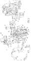
Figure 1 is an exploded isometric view of a circuit breaker in accordance with embodiments of the disclosed concept. -
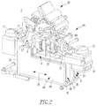
Figure 2 is an isometric view of the circuit breaker ofFigure 1 . -
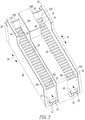
Figure 3 is an isometric view of the dual arc chamber and magnet assembly ofFigure 1 . -
Figure 4 is a cross-sectional view of the dual arc chamber and magnet assembly ofFigure 3 . -
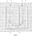
Figure 5 is a simplified cross-sectional view of the magnet, ferromagnetic frame and generally unidirectional magnetic field of the magnet assembly ofFigure 3 . -
Figure 6 is a cross-sectional view of an arc chamber and magnet assembly including two arc chambers, and a MOV printed circuit board in accordance with an embodiment of the disclosed concept. -
Figure 7 is an isometric view of the MOV printed circuit board ofFigure 6 . - As employed herein, the term "number" shall mean one or an integer greater than one (i.e., a plurality).
- As employed herein, the statement that two or more parts are "connected" or "coupled" together shall mean that the parts are joined together either directly or joined through one or more intermediate parts. Further, as employed herein, the statement that two or more parts are "attached" shall mean that the parts are joined together directly.
- The disclosed concept is described in association with a circuit breaker, although the disclosed concept is applicable to a wide range of electrical switching apparatus (e.g., without limitation, a switching device; a relay; a contactor; a disconnect switch).
- Referring to
Figures 1 and2 , an electrical switching apparatus, such as theexample circuit breaker 2, is shown. Thecircuit breaker 2 includes afirst arc runner 4, a second arc runner 6, a first (fixed)contact 8 in electrical communication with thefirst arc runner 4, and a second (fixed) contact 10 in electrical communication with the second arc runner 6. Amovable contact 12 of thecircuit breaker 2 includes afirst contact portion 14 and asecond contact portion 16 respectively cooperating with thefirst contact 8 and the second contact 10 to provide a closed contact position (not shown) in which themovable contact 12 electrically engages the first andsecond contacts 8,10, and an open contact position in which themovable contact 12 is disengaged from the first andsecond contacts 8,10. - The
circuit breaker 2 further includes twoarc chambers first arc chamber 18 includes afirst end 22, an oppositesecond end 24, alongitudinal axis 26 therebetween, and a plurality of first arc plates 28 (Figure 3 ) between thefirst end 22 and the oppositesecond end 24. One 28A of thefirst arc plates 28 at thefirst end 22 of thefirst arc chamber 18 is proximate thefirst arc runner 4. Another one 28B of thefirst arc plates 28 at the oppositesecond end 24 of thefirst arc chamber 18 is proximate thefirst portion 14 of themovable contact 12 as themovable contact 12 moves from the closed contact position toward the open contact position. - The
second arc chamber 20 includes afirst end 30, an oppositesecond end 32, alongitudinal axis 34 therebetween, and a plurality of second arc plates 36 (Figure 3 ) between thefirst end 30 and the oppositesecond end 32 of thesecond arc chamber 20. One 36A of thesecond arc plates 36 at thefirst end 30 of thesecond arc chamber 20 is proximate the second arc runner 6. Another one 36B of thesecond arc plates 36 at the oppositesecond end 32 of thesecond arc chamber 20 is proximate thesecond portion 16 of themovable contact 12 as themovable contact 12 moves from the closed contact position toward the open contact position. - An
operating mechanism 38 cooperates with themovable contact 12 to move themovable contact 12 between the closed contact position and the open contact position. - A magnet assembly 40 (best shown in
Figures 3 and4 ) cooperates with the first andsecond arc chambers Figure 5 ) normal to thelongitudinal axes second arc chambers Figure 3 ) of afirst arc 46 between thefirst contact 8 and thefirst portion 14 of themovable contact 12 as themovable contact 12 moves away from the closed contact position toward the open contact position, and normal to an opposite second direction 48 (Figure 3 ) of asecond arc 50 between the second contact 10 and thesecond portion 16 of themovable contact 12 as themovable contact 12 moves away from the closed contact position toward the open contact position. As a result, the generally unidirectionalmagnetic field 42 causes one of thefirst arc 46 and thesecond arc 50 to enter one of the first andsecond arc chambers line terminal 71 to second contact 10 tomovable contact portion 16 tomovable contact portion 14 tofirst contact 8 throughmagnetic trip coil 70 to loadterminal 72 causes thearcs respective directions Figure 3 ) between thefirst contact 8 and the second contact 10. - Each of the first and
second arc runners 4,6 has afirst portion 52 on which one of the first andsecond contacts 8,10, respectively, is disposed, asecond portion 54 normal to thefirst portion 52 and extending along thelongitudinal axis second arc chambers third portion 56 normal to thesecond portion 54 and extending parallel to one 28A,36A of thearc plates first end second arc chambers - The first direction 44 (
Figure 3 ) of thefirst arc 46 between thefirst contact 8 and thefirst portion 14 of themovable contact 12 as themovable contact 12 moves away from the closed contact position toward the open contact position is generally along thelongitudinal axis 26 of thefirst arc chamber 18 and toward thefirst end 22 of thefirst arc chamber 18. With the example direction of current flow, the generally unidirectional magnetic field 42 (Figure 5 ) causes thefirst arc 46 to enter thefirst arc chamber 18. The opposite second direction 48 (Figure 3 ) of thesecond arc 50 between the second contact 10 and thesecond portion 16 of themovable contact 12 as themovable contact 12 moves away from the closed contact position toward the open contact position is generally along thelongitudinal axis 34 of thesecond arc chamber 20 and away from thefirst end 30 of thesecond arc chamber 20. Again, with the example direction of current flow, the generally unidirectional magnetic field 42 (Figure 3 ) causes thesecond arc 50 to avoid thesecond arc chamber 20. Since the twofixed contacts 8,10 are disposed to one side of thecircuit breaker 2, current flow operatively associated with the twoarc chambers opposite directions 44,48 (Figure 3 ), thereby allowing use of the generally unidirectionalmagnetic field 42 to cause one of the twoarcs arc chambers arcs - As shown in
Figure 3 , thefirst arc plates 28 at the oppositesecond end 24 of thefirst arc chamber 18 and thesecond arc plates 36 at the oppositesecond end 32 of thesecond arc chamber 20 have afirst end 58 facing one of the first andsecond portions movable contact 12 and an opposite second end 60 (as shown with thearc plates Figure 5 ) is structured to cause one of thefirst arc 46 and thesecond arc 50 to define a corresponding one of two stable final arc positions 62 and 63 (Figure 5 ) among thefirst arc plates 28 and thesecond arc plates 36, respectively, and toward the oppositesecond end 60 of the first andsecond arc plates Figure 5 ) defines the stable final split arc position 62 or 63 since as thearc Figures 1 ,3 and5 ) in thearc chamber magnetic field 42 reverses atcorresponding region 64 or 65 (Figure 5 ) and causes a halt to the downward (with respect toFigures 1 ,3 and5 ) progression of the arc. This employs, for example, an "arc motion magnetic field" 42 as shown inFigure 5 . - The disclosed concept enables the direction of current flow between the
first contact 8 and the second contact 10 to be selected from the group consisting of alternating current, unidirectional positive direct current, unidirectional negative direct current, and bi-directional direct current. Operation with bi-directional current is made possible since thearc arc chambers arc contacts - Although the disclosed electrical switching apparatus is a circuit interrupter, such as the
example circuit breaker 2, it will be appreciated that the disclosed concept is applicable to any electrical switching apparatus, such as a disconnect switch. In the example embodiment, theoperating mechanism 38 includes atrip mechanism 66. Theexample trip mechanism 66 includes at least one of abimetal 68 and amagnetic trip coil 70. Theexample bimetal 68 is electrically connected to theload terminal 72 by aconductor 73. The examplemagnetic trip coil 70 is electrically connected between: (1) theload terminal 72 andconductor 75, and (2) thefirst contact 8 and aconductor 77. - The
example magnet assembly 40 includes a permanent magnet 74 (Figures 4 and5 ) and a ferromagnetic frame 76 (Figures 4 and5 ). A suitable electrical insulator, such as the example plastic moldedcase 84, includes afirst portion 78 holding thefirst arc chamber 18, a second portion 80 holding thesecond arc chamber 20, and athird portion 82 holding thepermanent magnet 74 between the first andsecond arc chambers permanent magnet 74 is a single permanent magnet, such as for example and without limitation, a single ceramic magnet (e.g., a non rare earth permanent magnet). The structure of theexample magnet assembly 40 provides a permanent arc motion magnetic field 42 (Figure 5 ). Since there is a singlepermanent magnet 74, there is sufficient space for a relatively larger ceramic magnet (e.g., larger than a relatively high energy rare earth permanent magnet). Alternatively, thepermanent magnet 74 can be a rare earth permanent magnet, such as for example and without limitation, a single Neodymium magnet (e.g., without limitation, a permanent magnet made from an alloy of neodymium, iron, and boron to form a Nd2Fe14B tetragonal crystalline structure), or a SmCo permanent magnet. Such rare earth magnets have a relatively stronger magnetic field, thereby permitting a relatively smaller permanent magnet thickness and allowing the arc chute width of thearc chambers arc chambers arc chambers - The example
ferromagnetic frame 76 is partially surrounded by the example moldedcase 84. As shown inFigure 5 , thepermanent magnet 74 has a first magnetic polarity (N) disposed toward thefirst arc chamber 18 and an opposite second magnetic polarity (S) disposed toward thesecond arc chamber 20. - In the example embodiment, the last arc plate 36B is optionally electrically connected to the
load terminal 72 by aconductor 86 and arc plate 28B is optionally electrically connected to load terminal 71 byjumper 69 in order to cause the ejected arc to be eliminated when the arc that enters the arc chute connects to either arc plate 28B or 36B (depending on the direction of the current being interrupted). It will be appreciated that this "tied" arrangement is optional and need not be employed. Elimination of the ejected arc will reduce the generation of arc damage and debris in the "unused arc chamber" and general mechanism areas. - Back-striking can result when an arc moves and lengthens across and into the
arc plates arc runners 4,6, thesplitter arc plates permanent magnet 74 and theferromagnetic frame 76 provide for effective arc splitting and minimal back-striking. - Optionally, as shown in
Figures 6 and 7 , a number ofMOVs 88 limit the series voltage of thearc plates board 90 is installed beneath themagnet 74. Twobridge contacts second arc plate 28C,28D;36C;36D (Figure 3 ) from acorresponding end Figure 3 ) of the twoarc chambers arc chambers MOVs 88 of thePC board 90 are employed (in series) to increase the effective MOV limiting voltage, while employing relatively small MOVs in a relatively small space, although it will be appreciated that any suitable number of MOVs can be employed. TheMOVs 88 are structured to limit a first voltage across a plurality of thefirst arc plates 28 and a second voltage across a plurality of thesecond arc plates 36. In the example embodiment, the number ofMOVs 88 are a plurality (e.g., three; any suitable number) ofMOVs 88 electrically connected in series between a first terminal defined by thefirst bridge contact 92 and a second terminal defined by thesecond bridge contact 94. Thefirst bridge contact 92 is electrically connected to one 28C of thefirst arc plates 28 proximate thefirst end 22 of thefirst arc chamber 18 and to one 36C of thesecond arc plates 36 proximate thefirst end 30 of thesecond arc chamber 20. Thesecond bridge contact 94 is electrically connected to one 28D of thefirst arc plates 28 proximate the oppositesecond end 24 of thefirst arc chamber 18 and to one 36D of thesecond arc plates 36 proximate the oppositesecond end 32 of thesecond arc chamber 20. It will be appreciated that other suitable voltage limiting devices, such as, for example and without limitation, zener diodes and transorbs, can be employed to perform the function described of the example MOVs. - Preferably, a number of the
first arc plates 28,28B,28D and a number of thesecond arc plates 36,36B,36D have a V-form, which V-form is known from alternating current circuit breakers. By this V-form, the arc will be forced to move to the root of the V. For example and without limitation, a dihedral form is employed that generates a dihedral effect in order to center the arc when moving into thearc plates - Preferably, suitable insulators (not shown) are disposed between the arc plate 28B or 28D and the
ends arc chambers line terminal 71, and provides an adequate dead stop. - The disclosed concept provides negligible arc flash (e.g., negligible display of relatively high temperature arc gas products).
- Many DC switching devices have a specified minimum interrupt current because the magnetic field per ampere requirement increases as the current decreases in order to assure suitable arc motion. These devices are not able to interrupt currents below this value. The disclosed concept provides switching performance over the current range from zero to a specified maximum rated interrupt current (e.g., without limitation, up to 1000 amperes) since sufficient magnetic field is present to move a relatively low
current arc - In the example embodiment, the open contact position is structured to interrupt current flow at a voltage of up to about 750 VDC. For example, 600 VDC to 1500 VDC solar string and combiner box applications employ a miniature relay or circuit breaker to replace fuses and provide a tripable and resetable device that incorporates solar arc fault algorithms. A single disclosed
circuit breaker 2 can address 600 VDC to 750 VDC applications. Two of the disclosedcircuit breakers 2 in series can address 1000 VDC to 1500 VDC applications. - The disclosed concept achieves 750 VDC bidirectional switching with only one
permanent magnet 74. The examplepermanent magnet 74 andferromagnetic frame 76 provide a suitable generally unidirectionalmagnetic field 42 to move example zero to 1000 ampere arcs to thesplitter arc plates arc chambers - Although a single
permanent magnet 74 is shown, it will be appreciated that two magnets can be employed to provide the generally unidirectionalmagnetic field 42. For example, the singlepermanent magnet 74 in the center of themagnet assembly 40 can be replaced by two (e.g., without limitation, half-thickness) magnets (not shown) on the two opposing sides of themagnet assembly 40, where both magnets have the same polarity direction in order to establish the generally unidirectionalmagnetic field 42. Another non-limiting alternative is to add a ferromagnetic steel plate (not shown) in the center of themagnet assembly 40 instead of thesingle magnet 74 in the center. - The disclosed
arc chambers - The particular arrangements disclosed are meant to be illustrative only and not limiting as to the scope of the disclosed concept which is defined by the appended claims.
Claims (15)
- An electrical switching apparatus (2) comprising:a first arc runner (4);a second arc runner (6):a first contact (8) in electrical communication with said first arc runner (4);a second contact (10) in electrical communication with said second arc runner (6);a movable contact (12) comprising a first portion (14) and a second portion (16) respectively cooperating with said first contact (8) and said second contact (10) to provide a closed contact position in which said movable contact (12) electrically engages said first and second contacts (8,10), and an open contact position in which said movable contact (12) is disengaged from said first and second contacts (8,10);a first arc chamber (18) comprising a first end (22), an opposite second end (24), a longitudinal axis (26) therebetween, and a plurality of first arc plates (28) between the first end and the opposite second end, one (28A) of the first arc plates (28) at the first end of the first arc chamber (18) being proximate said first arc runner (4), another one (28B) of the first arc plates (28) at the opposite second end of the first arc chamber (18) being proximate the first portion (14) of said movable contact (12) as said movable contact (12) moves from the closed contact position toward the open contact position;a second arc chamber (20) comprising a first end 30, an opposite second end (32), a longitudinal axis (34) therebetween, and a plurality of second arc plates (36) between the first end and the opposite second end of the second arc chamber (20), one (36A) of the second arc plates (36) at the first end of the second arc chamber (20) being proximate said second arc runner (6), another one (368) of the second arc plates (36) at the opposite second end of the second arc chamber (20) being proximate the second portion (16) of said movable contact (12) as said movable contact (12) moves from the closed contact position toward the open contact position;an operating mechanism (38) cooperating with said movable contact (12) to move said movable contact (12) between the closed contact position and the open contact position; characterised bya magnet assembly (40) comprising a permanent magnet (74) disposed between the first and second arc chambers (18,20), said permanent magnet cooperating with said first and second arc chambers (18,20) to establish a generally unidirectional magnetic field (42) normal to the longitudinal axes (26,34) of said first and second arc chambers (18,20), normal to a first direction (44) of a first arc (46) between the first contact (8) and the first portion (14) of the movable contact (12) as said movable contact (12) moves away from the closed contact position toward the open contact position, and normal to an opposite second direction (48) of a second arc (50) between the second contact (10) and the second portion (16) of the movable contact (12) as said movable contact (12) moves away from the closed contact position toward the open contact position, in order that said generally unidirectional magnetic field (42) causes one of the first arc (46) and the second arc (50) to enter one of said first and second arc chambers (18,20), respectively, depending upon a direction of current flow between the first contact (8) and the second contact (10).
- The electrical switching apparatus (2) of Claim 1 wherein each of said first and second arc runners (4,6) has a first portion (52) on which one of said first and second contacts (8,10), respectively, is disposed, a second portion (54) normal to the last said first portion and extending along the longitudinal axis (26,34) of one of said first and second arc chambers (18,20) respectively, and a third portion (56) normal to the last said second portion and extending parallel to one of the first and second arc plates (28)6) at the first end (22,30) of said first and second arc chambers (18,20) respectively.
- The electrical switching apparatus (2) of Claim 1 wherein said another one (36B) of the second arc plates (36) at the opposite second end of the second arc chamber (20) is electrically connected to a load terminal (72) in order to eliminate an ejected arc during interruption of the current flow.
- The electrical switching apparatus (2) of Claim 1 wherein the first direction (44) of the first arc (46) between the first contact (8) and the first portion (14) of the movable contact (12) as said movable contact (12) moves away from the closed contact position toward the open contact position is generally along the longitudinal axis (26) of said first arc chamber (18) and toward the first end (22) of the first arc chamber (18); wherein said generally unidirectional magnetic field (42) causes the first arc (46) to enter the first arc chamber (18); wherein the opposite second direction (48) of the second arc (50) between the second contact (10) and the second portion (16) of the movable contact (12) as said movable contact (12) moves away from the closed contact. position toward the open contact portion is generally along the longitudinal axis (34) of said second arc chamber (20) and away from the first end (30) of the second arc chamber (20); and wherein said generally unidirectional magnetic field (42) causes the second arc (50) to avoid the second arc chamber (20).
- The electrical switching apparatus (2) of Claim 1 wherein a magnitude of said current flow for interruption by said first, second and movable contacts is from zero amperes to a predetermined maximum amperes.
- The electrical switching apparatus (2) of Claim 1 wherein said first arc plates (28) at the opposite second end (24) of the first arc chamber (18) and said second arc plates (36) at the opposite second end (32) of the second arc chamber (20) have a first end (58) facing one of the first and second portions (14,16) of the movable contact (12) and an opposite second end (60); and wherein said generally unidirectional magnetic field (42) is structured to cause said one of the first arc (46) and the second arc (50) to define a stable final arc position (62;63) among said first arc plates (28) and said second arc plates (36), respectively, and toward the opposite second end (60) of said first and second arc plates (36).
- The electrical switching apparatus (2) of Claim 1 wherein said direction of current flow between the first contact (8) and the second contact (10) is selected from the group consisting of alternating current, positive direct current, negative direct current, and bi-directional direct current.
- The electrical switching apparatus (2) of Claim 1 wherein said electrical switching apparatus (2) is a circuit interrupter (2); wherein said operating mechanism (38) comprises a trip mechanism (66); and wherein said trip mechanism (66) comprises a bimetal (68) electrically connected to a load terminal (72).
- The electrical switching apparatus (2) of Claim 8 wherein said trip mechanism (66) comprises at least one of said bimetal (68) and a magnetic trip coil (70); and wherein said magnetic trip coil (70) is electrically connected between said terminal (72) and said first contact (8).
- The electrical switching apparatus (2) of Claim 1 wherein said magnet assembly (40) further comprises a ferromagnetic frame (76) and an insulative case (84) including a first portion (78) holding said first arc chamber (18), a second portion (80) holding said second arc chamber (20), and a third portion (82) holding said permanent magnet (74) between the first and second arc chambers (18,20).
- The electrical switching apparatus (2) of Claim 10 wherein the insulative case partially surrounds the first and second arc chambers.
- The electrical switching apparatus (2) of Claim 1 wherein said permanent magnet (74) has a first magnetic polarity (N) disposed toward said first arc chamber (18) and an opposite second magnetic polarity (S) disposed toward said second arc chamber (20).
- The electrical switching apparatus (2) of Claim 1 wherein the open contact position is structured to interrupt the current flow at a voltage of up to about 750 VDC.
- The electrical switching apparatus (2) of Claim 1 wherein said permanent magnet (74) is selected from the group consisting of a single Neodymium permanent magnet (74), a single SmCo permanent magnet, and a single ceramic magnet.
- The electrical switching apparatus (2) of Claim 1 wherein said magnet assembly (40) further comprises a number of MOVs (88) structured to limit a first voltage across a plurality of the first arc plates (28) and a second voltage across a plurality of the second arc plates (36); wherein said number ofMOVs are a plurality of MOVs (88) electrically connected in series between a first terminal (92) and a second terminal (94); wherein the first terminal (92) is electrically connected to one (28C) of the first arc plates {28) proximate the first end (22) of the first arc chamber (18) and to one (36C) of the second arc plates (36) proximate the first end (30) of the second arc chamber (20); and wherein the second terminal (94) is electrically connected to one (28D) of the first arc plates (28) proximate the opposite second end (24) of the first arc chamber (18) and to one (36D) of the second arc plates (36) proximate the opposite second end (32) of the second arc chamber (20).
Applications Claiming Priority (2)
| Application Number | Priority Date | Filing Date | Title |
|---|---|---|---|
| US201161557584P | 2011-11-09 | 2011-11-09 | |
| PCT/US2012/062678 WO2013070465A1 (en) | 2011-11-09 | 2012-10-31 | Electrical switching apparatus including magnet assembly and first and second arc chambers |
Publications (2)
| Publication Number | Publication Date |
|---|---|
| EP2777058A1 EP2777058A1 (en) | 2014-09-17 |
| EP2777058B1 true EP2777058B1 (en) | 2016-06-15 |
Family
ID=47221560
Family Applications (1)
| Application Number | Title | Priority Date | Filing Date |
|---|---|---|---|
| EP12790735.0A Active EP2777058B1 (en) | 2011-11-09 | 2012-10-31 | Electrical switching apparatus including magnet assembly and first and second arc chambers |
Country Status (3)
| Country | Link |
|---|---|
| US (1) | US8853586B2 (en) |
| EP (1) | EP2777058B1 (en) |
| WO (1) | WO2013070465A1 (en) |
Families Citing this family (12)
| Publication number | Priority date | Publication date | Assignee | Title |
|---|---|---|---|---|
| US20150014277A1 (en) * | 2013-07-15 | 2015-01-15 | Eaton Corporation | Interchangeable switching module and electrical switching apparatus including the same |
| DE102014004455B4 (en) * | 2014-03-27 | 2021-10-07 | Schaltbau Gmbh | Electrical switching device with improved arc extinguishing device and method for manufacturing such switching device |
| FR3027727B1 (en) | 2014-10-22 | 2016-12-09 | Socomec Sa | ELECTRIC ARC BREAK CHAMBER |
| US9552951B2 (en) * | 2015-03-06 | 2017-01-24 | Cooper Technologies Company | High voltage compact fusible disconnect switch device with magnetic arc deflection assembly |
| US9679720B1 (en) * | 2016-05-06 | 2017-06-13 | Carling Technologies, Inc. | Arc motivation device |
| US10854414B2 (en) | 2016-05-11 | 2020-12-01 | Eaton Intelligent Power Limited | High voltage electrical disconnect device with magnetic arc deflection assembly |
| US9966209B1 (en) | 2017-02-23 | 2018-05-08 | Carling Technologies, Inc. | Circuit breaker with arc shield |
| US10636607B2 (en) | 2017-12-27 | 2020-04-28 | Eaton Intelligent Power Limited | High voltage compact fused disconnect switch device with bi-directional magnetic arc deflection assembly |
| DE102020104258B4 (en) * | 2020-02-18 | 2022-09-29 | Schaltbau Gmbh | Switching device with at least two mutually communicating extinguishing areas |
| KR102558812B1 (en) * | 2020-03-13 | 2023-07-24 | 엘에스일렉트릭(주) | Arc extinguish part and air circuit breaker include the same |
| KR102666104B1 (en) * | 2021-05-06 | 2024-05-20 | 엘에스일렉트릭(주) | Arc extinguish part and air circuit breaker include the same |
| DE102022122226B4 (en) * | 2022-09-02 | 2025-11-27 | Schaltbau Gmbh | Switching device with arc limiter |
Family Cites Families (10)
| Publication number | Priority date | Publication date | Assignee | Title |
|---|---|---|---|---|
| DE2525810C3 (en) * | 1975-06-06 | 1986-02-13 | Licentia Patent-Verwaltungs-Gmbh, 6000 Frankfurt | DC and AC voltage switching air contactor with higher switching capacity with permanent magnetic arc blowing system |
| US4820205A (en) * | 1985-04-09 | 1989-04-11 | Square D Company | Terminal structure for a coil |
| JP2538991B2 (en) * | 1988-06-09 | 1996-10-02 | 松下電工株式会社 | Remote control type circuit breaker |
| US5004874A (en) | 1989-11-13 | 1991-04-02 | Eaton Corporation | Direct current switching apparatus |
| US5130504A (en) | 1990-08-29 | 1992-07-14 | Eaton Corporation | Bi-directional direct current switching apparatus having bifurcated arc runners extending into separate arc extinguishing chambers |
| US5266760A (en) * | 1992-08-06 | 1993-11-30 | Eaton Corporation | Molded case circuit breaker |
| JP3321963B2 (en) * | 1994-02-22 | 2002-09-09 | 株式会社デンソー | Plunger type electromagnetic relay |
| EP1548772A1 (en) * | 2003-12-22 | 2005-06-29 | ABB Schweiz Holding AG | Arc extinguishing installation for a circuit breaker with a double break |
| DE50309487D1 (en) | 2003-12-22 | 2008-05-08 | Abb Schweiz Ag | Arc quenching device for circuit breaker with double break |
| DE102007054958A1 (en) * | 2007-11-17 | 2009-06-04 | Moeller Gmbh | Switching device for DC applications |
-
2012
- 2012-10-31 WO PCT/US2012/062678 patent/WO2013070465A1/en not_active Ceased
- 2012-10-31 EP EP12790735.0A patent/EP2777058B1/en active Active
- 2012-10-31 US US13/664,555 patent/US8853586B2/en active Active
Also Published As
| Publication number | Publication date |
|---|---|
| EP2777058A1 (en) | 2014-09-17 |
| WO2013070465A1 (en) | 2013-05-16 |
| US8853586B2 (en) | 2014-10-07 |
| US20130112655A1 (en) | 2013-05-09 |
Similar Documents
| Publication | Publication Date | Title |
|---|---|---|
| EP2777058B1 (en) | Electrical switching apparatus including magnet assembly and first and second arc chambers | |
| EP2463880B1 (en) | Direct current arc chamber, and bi-directinal direct current electrical switching apparatus employing the same | |
| US8159319B2 (en) | Double-breaking contact system for a low voltage circuit breaker, a molded case circuit breaker comprising the double-breaking contact system, and a method for breaking a circuit | |
| EP3223293B1 (en) | Electrical switching apparatus, and arc chamber assembly and associated circuit protection method | |
| EP2980821B1 (en) | Switchgear | |
| US8368492B1 (en) | Bidirectional direct current electrical switching apparatus | |
| CN104321847B (en) | DC circuit circuit-breaker and DC circuit circuit breaking apparatus | |
| US20150014277A1 (en) | Interchangeable switching module and electrical switching apparatus including the same | |
| KR101568685B1 (en) | Arc extinguishing mechanism of direct current switch and direct current switch and direct current circuit breaker having arc extinguishing mechanism | |
| US20200411259A1 (en) | Circuit breaker for isolating an electrical circuit | |
| CN108352266B (en) | Electrical switchgear and slot motor therefor | |
| CN114551131A (en) | Direct current arc extinguishing device and motor type direct current switch equipment | |
| EP3266029B1 (en) | High voltage compact fusible disconnect switch device with magnetic arc deflection assembly | |
| US9147541B2 (en) | Circuit breaker comprising ventilation channels for efficient heat dissipation | |
| US20170271112A1 (en) | Slot Motor Configuration for High Amperage Multi-Finger Circuit Breaker | |
| US20190198278A1 (en) | High voltage compact fused disconnect switch device with bi-directional magnetic arc deflection assembly | |
| CN201327805Y (en) | Gassing insulator component, conductor component and electric switch device utilizing same | |
| CN110197781B (en) | Structure for double break contacts with electromagnetic arc blow | |
| CN115547766B (en) | Miniature circuit breaker | |
| EP1218899B1 (en) | Electric pole for low-voltage power circuit breaker | |
| CN113632193A (en) | circuit breaker | |
| KR101565454B1 (en) | Direct current switch and direct current circuit breaker | |
| CN113471032A (en) | Electromechanical compact protective switching device | |
| SE460812B (en) | switchgear | |
| CN113889380A (en) | Small-size direct current quick circuit breaker |
Legal Events
| Date | Code | Title | Description |
|---|---|---|---|
| PUAI | Public reference made under article 153(3) epc to a published international application that has entered the european phase |
Free format text: ORIGINAL CODE: 0009012 |
|
| 17P | Request for examination filed |
Effective date: 20140512 |
|
| AK | Designated contracting states |
Kind code of ref document: A1 Designated state(s): AL AT BE BG CH CY CZ DE DK EE ES FI FR GB GR HR HU IE IS IT LI LT LU LV MC MK MT NL NO PL PT RO RS SE SI SK SM TR |
|
| DAX | Request for extension of the european patent (deleted) | ||
| GRAP | Despatch of communication of intention to grant a patent |
Free format text: ORIGINAL CODE: EPIDOSNIGR1 |
|
| INTG | Intention to grant announced |
Effective date: 20160112 |
|
| RIN1 | Information on inventor provided before grant (corrected) |
Inventor name: ZHOU, XIN Inventor name: THEISEN, PETER J. Inventor name: JUDS, MARK A. Inventor name: ROLLMANN, PAUL J. |
|
| GRAS | Grant fee paid |
Free format text: ORIGINAL CODE: EPIDOSNIGR3 |
|
| GRAA | (expected) grant |
Free format text: ORIGINAL CODE: 0009210 |
|
| AK | Designated contracting states |
Kind code of ref document: B1 Designated state(s): AL AT BE BG CH CY CZ DE DK EE ES FI FR GB GR HR HU IE IS IT LI LT LU LV MC MK MT NL NO PL PT RO RS SE SI SK SM TR |
|
| REG | Reference to a national code |
Ref country code: CH Ref legal event code: EP Ref country code: GB Ref legal event code: FG4D |
|
| REG | Reference to a national code |
Ref country code: IE Ref legal event code: FG4D |
|
| REG | Reference to a national code |
Ref country code: AT Ref legal event code: REF Ref document number: 806859 Country of ref document: AT Kind code of ref document: T Effective date: 20160715 |
|
| REG | Reference to a national code |
Ref country code: DE Ref legal event code: R096 Ref document number: 602012019599 Country of ref document: DE |
|
| REG | Reference to a national code |
Ref country code: NL Ref legal event code: FP |
|
| REG | Reference to a national code |
Ref country code: FR Ref legal event code: PLFP Year of fee payment: 5 |
|
| REG | Reference to a national code |
Ref country code: LT Ref legal event code: MG4D |
|
| PG25 | Lapsed in a contracting state [announced via postgrant information from national office to epo] |
Ref country code: NO Free format text: LAPSE BECAUSE OF FAILURE TO SUBMIT A TRANSLATION OF THE DESCRIPTION OR TO PAY THE FEE WITHIN THE PRESCRIBED TIME-LIMIT Effective date: 20160915 Ref country code: LT Free format text: LAPSE BECAUSE OF FAILURE TO SUBMIT A TRANSLATION OF THE DESCRIPTION OR TO PAY THE FEE WITHIN THE PRESCRIBED TIME-LIMIT Effective date: 20160615 Ref country code: FI Free format text: LAPSE BECAUSE OF FAILURE TO SUBMIT A TRANSLATION OF THE DESCRIPTION OR TO PAY THE FEE WITHIN THE PRESCRIBED TIME-LIMIT Effective date: 20160615 |
|
| PG25 | Lapsed in a contracting state [announced via postgrant information from national office to epo] |
Ref country code: GR Free format text: LAPSE BECAUSE OF FAILURE TO SUBMIT A TRANSLATION OF THE DESCRIPTION OR TO PAY THE FEE WITHIN THE PRESCRIBED TIME-LIMIT Effective date: 20160916 Ref country code: HR Free format text: LAPSE BECAUSE OF FAILURE TO SUBMIT A TRANSLATION OF THE DESCRIPTION OR TO PAY THE FEE WITHIN THE PRESCRIBED TIME-LIMIT Effective date: 20160615 Ref country code: SE Free format text: LAPSE BECAUSE OF FAILURE TO SUBMIT A TRANSLATION OF THE DESCRIPTION OR TO PAY THE FEE WITHIN THE PRESCRIBED TIME-LIMIT Effective date: 20160615 Ref country code: LV Free format text: LAPSE BECAUSE OF FAILURE TO SUBMIT A TRANSLATION OF THE DESCRIPTION OR TO PAY THE FEE WITHIN THE PRESCRIBED TIME-LIMIT Effective date: 20160615 Ref country code: RS Free format text: LAPSE BECAUSE OF FAILURE TO SUBMIT A TRANSLATION OF THE DESCRIPTION OR TO PAY THE FEE WITHIN THE PRESCRIBED TIME-LIMIT Effective date: 20160615 |
|
| PG25 | Lapsed in a contracting state [announced via postgrant information from national office to epo] |
Ref country code: RO Free format text: LAPSE BECAUSE OF FAILURE TO SUBMIT A TRANSLATION OF THE DESCRIPTION OR TO PAY THE FEE WITHIN THE PRESCRIBED TIME-LIMIT Effective date: 20160615 Ref country code: SK Free format text: LAPSE BECAUSE OF FAILURE TO SUBMIT A TRANSLATION OF THE DESCRIPTION OR TO PAY THE FEE WITHIN THE PRESCRIBED TIME-LIMIT Effective date: 20160615 Ref country code: EE Free format text: LAPSE BECAUSE OF FAILURE TO SUBMIT A TRANSLATION OF THE DESCRIPTION OR TO PAY THE FEE WITHIN THE PRESCRIBED TIME-LIMIT Effective date: 20160615 Ref country code: IS Free format text: LAPSE BECAUSE OF FAILURE TO SUBMIT A TRANSLATION OF THE DESCRIPTION OR TO PAY THE FEE WITHIN THE PRESCRIBED TIME-LIMIT Effective date: 20161015 |
|
| PG25 | Lapsed in a contracting state [announced via postgrant information from national office to epo] |
Ref country code: PL Free format text: LAPSE BECAUSE OF FAILURE TO SUBMIT A TRANSLATION OF THE DESCRIPTION OR TO PAY THE FEE WITHIN THE PRESCRIBED TIME-LIMIT Effective date: 20160615 Ref country code: PT Free format text: LAPSE BECAUSE OF FAILURE TO SUBMIT A TRANSLATION OF THE DESCRIPTION OR TO PAY THE FEE WITHIN THE PRESCRIBED TIME-LIMIT Effective date: 20161017 Ref country code: SM Free format text: LAPSE BECAUSE OF FAILURE TO SUBMIT A TRANSLATION OF THE DESCRIPTION OR TO PAY THE FEE WITHIN THE PRESCRIBED TIME-LIMIT Effective date: 20160615 Ref country code: ES Free format text: LAPSE BECAUSE OF FAILURE TO SUBMIT A TRANSLATION OF THE DESCRIPTION OR TO PAY THE FEE WITHIN THE PRESCRIBED TIME-LIMIT Effective date: 20160615 Ref country code: BE Free format text: LAPSE BECAUSE OF NON-PAYMENT OF DUE FEES Effective date: 20160615 |
|
| REG | Reference to a national code |
Ref country code: DE Ref legal event code: R097 Ref document number: 602012019599 Country of ref document: DE |
|
| PLBE | No opposition filed within time limit |
Free format text: ORIGINAL CODE: 0009261 |
|
| STAA | Information on the status of an ep patent application or granted ep patent |
Free format text: STATUS: NO OPPOSITION FILED WITHIN TIME LIMIT |
|
| 26N | No opposition filed |
Effective date: 20170316 |
|
| PG25 | Lapsed in a contracting state [announced via postgrant information from national office to epo] |
Ref country code: DK Free format text: LAPSE BECAUSE OF FAILURE TO SUBMIT A TRANSLATION OF THE DESCRIPTION OR TO PAY THE FEE WITHIN THE PRESCRIBED TIME-LIMIT Effective date: 20160615 |
|
| REG | Reference to a national code |
Ref country code: CH Ref legal event code: PL |
|
| REG | Reference to a national code |
Ref country code: IE Ref legal event code: MM4A |
|
| PG25 | Lapsed in a contracting state [announced via postgrant information from national office to epo] |
Ref country code: CH Free format text: LAPSE BECAUSE OF NON-PAYMENT OF DUE FEES Effective date: 20161031 Ref country code: LI Free format text: LAPSE BECAUSE OF NON-PAYMENT OF DUE FEES Effective date: 20161031 |
|
| PG25 | Lapsed in a contracting state [announced via postgrant information from national office to epo] |
Ref country code: LU Free format text: LAPSE BECAUSE OF NON-PAYMENT OF DUE FEES Effective date: 20161031 Ref country code: SI Free format text: LAPSE BECAUSE OF FAILURE TO SUBMIT A TRANSLATION OF THE DESCRIPTION OR TO PAY THE FEE WITHIN THE PRESCRIBED TIME-LIMIT Effective date: 20160615 |
|
| REG | Reference to a national code |
Ref country code: FR Ref legal event code: PLFP Year of fee payment: 6 |
|
| PG25 | Lapsed in a contracting state [announced via postgrant information from national office to epo] |
Ref country code: IE Free format text: LAPSE BECAUSE OF NON-PAYMENT OF DUE FEES Effective date: 20161031 |
|
| PG25 | Lapsed in a contracting state [announced via postgrant information from national office to epo] |
Ref country code: HU Free format text: LAPSE BECAUSE OF FAILURE TO SUBMIT A TRANSLATION OF THE DESCRIPTION OR TO PAY THE FEE WITHIN THE PRESCRIBED TIME-LIMIT; INVALID AB INITIO Effective date: 20121031 |
|
| PG25 | Lapsed in a contracting state [announced via postgrant information from national office to epo] |
Ref country code: MT Free format text: LAPSE BECAUSE OF NON-PAYMENT OF DUE FEES Effective date: 20161031 Ref country code: CY Free format text: LAPSE BECAUSE OF FAILURE TO SUBMIT A TRANSLATION OF THE DESCRIPTION OR TO PAY THE FEE WITHIN THE PRESCRIBED TIME-LIMIT Effective date: 20160615 Ref country code: MC Free format text: LAPSE BECAUSE OF FAILURE TO SUBMIT A TRANSLATION OF THE DESCRIPTION OR TO PAY THE FEE WITHIN THE PRESCRIBED TIME-LIMIT Effective date: 20160615 Ref country code: MK Free format text: LAPSE BECAUSE OF FAILURE TO SUBMIT A TRANSLATION OF THE DESCRIPTION OR TO PAY THE FEE WITHIN THE PRESCRIBED TIME-LIMIT Effective date: 20160615 |
|
| PG25 | Lapsed in a contracting state [announced via postgrant information from national office to epo] |
Ref country code: BG Free format text: LAPSE BECAUSE OF FAILURE TO SUBMIT A TRANSLATION OF THE DESCRIPTION OR TO PAY THE FEE WITHIN THE PRESCRIBED TIME-LIMIT Effective date: 20160615 |
|
| REG | Reference to a national code |
Ref country code: FR Ref legal event code: PLFP Year of fee payment: 7 |
|
| PG25 | Lapsed in a contracting state [announced via postgrant information from national office to epo] |
Ref country code: TR Free format text: LAPSE BECAUSE OF FAILURE TO SUBMIT A TRANSLATION OF THE DESCRIPTION OR TO PAY THE FEE WITHIN THE PRESCRIBED TIME-LIMIT Effective date: 20160615 Ref country code: AL Free format text: LAPSE BECAUSE OF FAILURE TO SUBMIT A TRANSLATION OF THE DESCRIPTION OR TO PAY THE FEE WITHIN THE PRESCRIBED TIME-LIMIT Effective date: 20160615 |
|
| REG | Reference to a national code |
Ref country code: AT Ref legal event code: UEP Ref document number: 806859 Country of ref document: AT Kind code of ref document: T Effective date: 20160615 |
|
| REG | Reference to a national code |
Ref country code: GB Ref legal event code: 732E Free format text: REGISTERED BETWEEN 20181115 AND 20181130 |
|
| REG | Reference to a national code |
Ref country code: DE Ref legal event code: R082 Ref document number: 602012019599 Country of ref document: DE Ref country code: DE Ref legal event code: R081 Ref document number: 602012019599 Country of ref document: DE Owner name: EATON INTELLIGENT POWER LIMITED, IE Free format text: FORMER OWNER: EATON CORP., CLEVELAND, OHIO, US |
|
| REG | Reference to a national code |
Ref country code: AT Ref legal event code: PC Ref document number: 806859 Country of ref document: AT Kind code of ref document: T Owner name: EATON INTELLIGENT POWER LIMITED, IE Effective date: 20190531 |
|
| REG | Reference to a national code |
Ref country code: NL Ref legal event code: PD Owner name: EATON INTELLIGENT POWER LIMITED; IE Free format text: DETAILS ASSIGNMENT: CHANGE OF OWNER(S), ASSIGNMENT; FORMER OWNER NAME: EATON CORPORATION Effective date: 20210630 |
|
| P01 | Opt-out of the competence of the unified patent court (upc) registered |
Effective date: 20230521 |
|
| PGFP | Annual fee paid to national office [announced via postgrant information from national office to epo] |
Ref country code: NL Payment date: 20250923 Year of fee payment: 14 Ref country code: IT Payment date: 20250923 Year of fee payment: 14 |
|
| PGFP | Annual fee paid to national office [announced via postgrant information from national office to epo] |
Ref country code: GB Payment date: 20250923 Year of fee payment: 14 |
|
| PGFP | Annual fee paid to national office [announced via postgrant information from national office to epo] |
Ref country code: FR Payment date: 20250924 Year of fee payment: 14 |
|
| PGFP | Annual fee paid to national office [announced via postgrant information from national office to epo] |
Ref country code: CZ Payment date: 20250929 Year of fee payment: 14 |
|
| PGFP | Annual fee paid to national office [announced via postgrant information from national office to epo] |
Ref country code: DE Payment date: 20250923 Year of fee payment: 14 |
|
| PGFP | Annual fee paid to national office [announced via postgrant information from national office to epo] |
Ref country code: AT Payment date: 20250926 Year of fee payment: 14 |