EP2777036B1 - Exhibiting device for supporting informative material particularly for containers, urban furnishing elements and the like - Google Patents
Exhibiting device for supporting informative material particularly for containers, urban furnishing elements and the like Download PDFInfo
- Publication number
- EP2777036B1 EP2777036B1 EP12777901.5A EP12777901A EP2777036B1 EP 2777036 B1 EP2777036 B1 EP 2777036B1 EP 12777901 A EP12777901 A EP 12777901A EP 2777036 B1 EP2777036 B1 EP 2777036B1
- Authority
- EP
- European Patent Office
- Prior art keywords
- plate
- exhibiting device
- contoured
- openings
- coupling
- Prior art date
- Legal status (The legal status is an assumption and is not a legal conclusion. Google has not performed a legal analysis and makes no representation as to the accuracy of the status listed.)
- Active
Links
Images

Classifications
-
- G—PHYSICS
- G09—EDUCATION; CRYPTOGRAPHY; DISPLAY; ADVERTISING; SEALS
- G09F—DISPLAYING; ADVERTISING; SIGNS; LABELS OR NAME-PLATES; SEALS
- G09F15/00—Boards, hoardings, pillars, or like structures for notices, placards, posters, or the like
- G09F15/0006—Boards, hoardings, pillars, or like structures for notices, placards, posters, or the like planar structures comprising one or more panels
- G09F15/0043—Boards, hoardings, pillars, or like structures for notices, placards, posters, or the like planar structures comprising one or more panels connected to a receptacle of public utility, e.g. a waste receptacle
Definitions
- the present invention relates to an exhibiting device, hereafter also referred to as an exhibitor, for supporting informative material particularly for containers, urban furnishing elements and the like.
- the walls of containers are generally provided with heterogeneous supports, such as plastic stickers, riveted aluminum panels, or indications written by means of spray paint.
- the containers presently on the market differ enormously among each other, in particular in terms of the material of which they are made (iron, stainless steel, aluminum, plastic with injection molding, plastic with rotational molding, fiberglass), as well as the geometric shape, the capacity (from 80 liters up to 10 cubic meters) and the system of hooking for emptying (side loading, rear loading, front loading, with ring-shaped or mushroom-shaped upper hooks for cranes).
- EP 1 228 727 discloses the preamble of claim 1.
- the aim of the present invention is to solve the above-mentioned drawbacks, by providing an exhibitor for supporting informative material particularly for containers, urban furnishing elements and the like which is highly versatile.
- an object of the invention is to provide an exhibitor for supporting informative material particularly for containers, urban furnishing elements and the like which ensures an easy replacement of the informative material exhibited therein.
- Another object of the invention is to provide an exhibitor for supporting informative material particularly for containers, urban furnishing elements and the like which preserves the informative material exhibited therein from degradation.
- Another object of the present invention is to provide an exhibitor for supporting informative material particularly for containers, urban furnishing elements and the like which is easy and safe to install.
- Another object of the present invention is to provide an exhibitor for supporting informative material particularly for containers, urban furnishing elements and the like which is low-cost, easily and practically implemented and safe in application.
- the reference numeral 1 generally designates an exhibitor for supporting informative material particularly for containers, urban furnishing elements and the like.
- the exhibitor 1 comprises at least one plate 2 which is provided with drainage holes (which will be described and illustrated below) and with at least one contoured perimetric edge 3.
- Such plate 2 is intended to accommodate stably at least one panel 4.
- the panel 4 is a rigid or semirigid support which bears the informative or advertising content to be exhibited. It can be made of plastic material, cardboard, plastic-coated card, aluminum or a combination of these materials.
- the exhibitor 1, according to the invention, also comprises a closure element 5 which is provided with means 6 for detachable coupling with the contoured perimetric edge 3.
- the closure element 5 couples the panel 4 to the plate 2.
- the coupling means 6 and the contoured perimetric edge 3 comprise respective mated and complementary profiles.
- the exhibitor 1 comprises at least two plates 2a and 2b, which are mutually connected by way of the mutual juxtaposition of the mated and complementary profiles of the contoured perimetric edges 3a and 3b thereof.
- contoured perimetric edge 3 and the coupling means 6 are constituted respectively by two mutually offset series of protrusions 7 and recesses 8.
- Both of these protrusions 7 and recesses 8 are substantially trapezoidal.
- the two series of protrusions 7 and recesses 8 are respectively arranged on two different planes which are parallel to the plane defined by the plate 2.
- the staggered arrangement of the two series of protrusions 7 and recesses 8 is such that each protrusion 7 of the first series is positioned at a recess of the second series, and vice versa.
- the protrusions 7 of the closure element 5 and of the contoured perimetric edge 3 respectively have through cavities 9 and openings 10 (specifically these through cavities 9 and openings 10 constitute part of the drainage holes).
- the cavities 9 are aligned with the respective openings 10 for the optional accommodation of corresponding locking means 11, which allow the mutual stable locking in this configuration.
- a permanent locking can be envisaged, by way of adhesive bonding, on one side of the exhibitor 1, and a temporary locking on the other side, in order to enable a quick replacement of the panel 4.
- one or more antitheft elements are moreover provided, such as for example a padlock or a screw with self-locking nut.
- the exhibitor 1 comprises two plates 2, (2a and 2b), and the protrusions 7 (in particular the protrusions designed to mutually connect 7a and 7b) of a contoured perimetric edge 4 (specifically the mutually opposite edges 3a and 3b) of a first and of a second plate 2a and 2b have a plurality of openings 10 (in detail, the openings 10a and 10b respectively).
- the openings 10a of the first plate 2a are aligned with the openings 11b of the second plate 2b, for the optional accommodation of corresponding locking means 11, which allow stable coupling in this configuration.
- the mutual locking between the plates 2a and 2b can be performed by adhesive bonding.
- the plate 2 has at least one guiding portion 12 in order to facilitate the slideable insertion of at least one panel 4 on the plate 2 itself.
- Such guiding portion 12 has a first part 13 which is integral with and perpendicular to the plate 2, and a second part 14, which is integral with the first part 13 and arranged substantially parallel to the plate 2.
- the different length of the first part 13 of each guiding portion 12 determines the distance of the respective panel 4, accommodated thereon, from the plate 2.
- an outflow passage 15 is arranged, so as to allow efficient draining of liquids (such passages 15 constitute part of the drainage holes) and the simultaneous outflow of dust and residues in general.
- the guiding portion 12 can be preferably U-shaped or V-shaped, but other embodiments are not ruled out.
- the guiding portion 12 can be a single, double or multiple track, for example E-shaped.
- Such shape structure enables the simultaneous insertion of two or more panels 4, arranging them on different planes which are parallel to the plate 2.
- Such possibility makes it possible, for example, to insert a panel 4 with an advertising image and above this another two informative panels 4, smaller than the first, indicating the no-stopping sign and the type of refuse to discard in the container.
- the advertising panel 4 even if positioned below the two informative panels 4, is visible as well, since, the latter two being smaller in size, they only partially cover the surface of the advertising panel 4, which thus remains visible to the user.
- At least one of the drainage holes, the through cavities 9, the openings 10 and the passages 15 has respective identification markings for the selective accommodation of fixing elements 16 which make it possible to firmly couple the exhibitor 1 to the respective wall 17 of a container 18, urban furnishing element and the like.
- the exhibitor 1 can be firmly coupled to the respective wall 17 of a container 18, urban furnishing element and the like by adhesive bonding.
- the characteristics of the locking means 11 and the fixing elements 16 are such that they do not protrude forward, so as not to interfere with the sliding of the panel 4, or rearward, so as not to obstruct the correct positioning on the wall.
- the exhibitor 1 can comprise at least one component selected from a loudspeaker, at least one light source and at least one display screen, for the distribution of informative and/or advertising messages.
- the light source can for example be used to notify the user of the status of the container 18 i.e. a green light indicates that the container 18 is operational and has space available to contain the refuse, whereas a red light indicates that the container 18 is out of service because it is full.
- the exhibitor 1 also makes it possible to accommodate small loudspeakers for the aural diffusion of acoustic signals or synthesized voice.
- the apparatuses for controlling and powering such components can be installed behind the plate 2 by arrangement along a plane parallel thereto, or inside the container 18 in a suitable portion thereof.
- a graduated scale is arranged on the plate 2 so as to facilitate the correct positioning and alignment of the exhibitor 1 on the wall 17.
- Such scale is a sequence of equidistant lines, with distance graduation given in mm or cm and/or given in inches.
- the lines are distributed along a straight line and are numbered with increasing numerals.
- Such scale is generally positioned at the bottom on the left and it enables correct positioning by the operator with respect to the ground and/or with respect to a specific reference point arranged on the container 18.
- the walls of the containers can have ribbing or reinforcement supports thus creating surfaces that are extremely uneven.
- adapted shims can moreover be provided to be interposed between the exhibitor 1 and the wall 17 of the container 18.
- the plate 2 has a plurality of through eyelets 19 for optimum draining and the lightening thereof.
- One or more exhibitors 1 can be applied side by side, overlaid or with any other arrangement, to the wall 17 of a container 18, so that the black centering line remains visible.
- Such line which characterizes side-loading containers, is the line that enables the automatic emptying of the containers.
- the exhibitor 1 can be positioned with any orientation (horizontal, vertical, diagonal, inclined) along the walls 17 or the cover of the container 18.
- the exhibitor 1 to other urban furnishing elements such as a post, or a wall.
- the shape and size of the exhibitor 1 required are determined.
- the plates 2, if there is more than one, are fixed to each other by adhesive bonding or by locking means 11.
- the operator proceeds by identifying the position of the exhibitor 1 on the wall 17, optionally by using the graduated scale provided, and the exhibitor 1, without the closure element, is coupled, by means of the fixing elements 16 or adhesive bonding, to the wall 17 of the container 18.
- the operator can thus choose the most suitable fixing points for that specific container 18 using the respective identification markings without the need to make holes in the plate 2 or the exhibitor 1.
- the operator proceeds by inserting one or more panels 4, according to requirements, into the guiding portions 12, after which the closure element 5 is coupled to the contoured perimetric edge 3 by the locking means 11 or by adhesive bonding.
- the exhibitor 1, according to the invention enables an easy and safe installation.
- the exhibitor 1 for supporting informative material particularly for containers, urban furnishing elements and the like also attains the high versatility required in that the modularity of the plates 2 makes it possible to freely compose it thus obtaining the desired final size, in relation to the size and to the shape structure of the container 18.
- the exhibitor 1, according to the invention is such as to enable a quick replacement of the informative material exhibited therein.
- the exhibitor according to the invention makes it possible to preserve the informative material exhibited therein from degradation.
- the plurality of through eyelets 19 make it possible to reduce the weight of the exhibitor 1, thus facilitating the transport and installation thereof, as well as the quantity of material necessary to produce it with simultaneous reduction of costs.
- the lower weight of the exhibitor also implies a lower weight of the container 18, which is thus easier to shift and move both manually and by means of a mechanized lifting apparatus.
- the presence of guiding portions 12, in particular the presence of the passages 15, enable the expulsion of the dust deposited on the exhibitor 1.
- the dust is shifted until it naturally exits from the passages 15 arranged at the rear of the guiding portions 12.
- the exhibitor 1 for supporting informative material particularly for containers, urban furnishing elements and the like fully achieves the set aim in that it ensures considerable versatility of use, thanks to the modularity that distinguishes it.
- the materials employed, as well as the dimensions, may be any according to requirements and to the state of the art.
Landscapes
- Physics & Mathematics (AREA)
- General Physics & Mathematics (AREA)
- Engineering & Computer Science (AREA)
- Theoretical Computer Science (AREA)
- Details Of Rigid Or Semi-Rigid Containers (AREA)
- Liquid Crystal Substances (AREA)
- Packages (AREA)
- Packaging Of Annular Or Rod-Shaped Articles, Wearing Apparel, Cassettes, Or The Like (AREA)
- Illuminated Signs And Luminous Advertising (AREA)
- Assembled Shelves (AREA)
Description
- The present invention relates to an exhibiting device, hereafter also referred to as an exhibitor, for supporting informative material particularly for containers, urban furnishing elements and the like.
- Many techniques are known which allow the walls of refuse containers to be used to convey information and advertising.
- In fact, according to the Italian Highway Code, refuse containers, if positioned on the road bed, must necessarily have portions with high refraction.
- Moreover they must have a "no stopping" sign in order to ensure the space necessary for the refuse collection vehicle to carry out the operations of emptying the refuse container.
- To this must be added the need to also bear a series of items of information that assist the user in using the container correctly, such as for example the type of refuse to be discarded in the container.
- For this reason, the walls of containers are generally provided with heterogeneous supports, such as plastic stickers, riveted aluminum panels, or indications written by means of spray paint.
- Such techniques however have the drawback that the images and the wordings tend to lose their original coloring quickly, effectively resulting in illegibility of the information on them.
- In particular, urban pollution, atmospheric agents, the shapes and ribbing of the walls of the containers, and the materials of which the containers are made are among the main causes of the rapid deterioration of indications, which must thus be frequently replaced.
- Moreover, the containers presently on the market differ enormously among each other, in particular in terms of the material of which they are made (iron, stainless steel, aluminum, plastic with injection molding, plastic with rotational molding, fiberglass), as well as the geometric shape, the capacity (from 80 liters up to 10 cubic meters) and the system of hooking for emptying (side loading, rear loading, front loading, with ring-shaped or mushroom-shaped upper hooks for cranes).
- For this reason, if panels are used as the support for informative or advertising material, they will have a different size and shape depending on the type of box on which they will be applied, with consequent increase in costs for their production and installation.
-
EP 1 228 727claim 1. - The aim of the present invention is to solve the above-mentioned drawbacks, by providing an exhibitor for supporting informative material particularly for containers, urban furnishing elements and the like which is highly versatile.
- Within this aim, an object of the invention is to provide an exhibitor for supporting informative material particularly for containers, urban furnishing elements and the like which ensures an easy replacement of the informative material exhibited therein.
- Another object of the invention is to provide an exhibitor for supporting informative material particularly for containers, urban furnishing elements and the like which preserves the informative material exhibited therein from degradation.
- Another object of the present invention is to provide an exhibitor for supporting informative material particularly for containers, urban furnishing elements and the like which is easy and safe to install.
- Another object of the present invention is to provide an exhibitor for supporting informative material particularly for containers, urban furnishing elements and the like which is low-cost, easily and practically implemented and safe in application.
- This aim and these objects are achieved by an exhibition device according to
claim 1. Further characteristics and advantages of the invention will become better apparent from the detailed description that follows of a preferred, but not exclusive, embodiment of the exhibitor for supporting informative material particularly for containers, urban furnishing elements and the like, according to the invention, which is illustrated by way of non-limiting example in the accompanying drawings, wherein: -
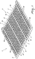
Figure 1 is a perspective view of a portion of the exhibitor according to the invention; -
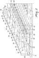
Figure 2 is a perspective view of a detail of the exhibitor according to the invention; -
Figure 3 is a perspective view of a possible embodiment of the exhibitor according to the invention; -
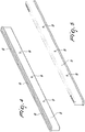
Figure 4 is a perspective view from below of a component of the exhibitor according to the invention; -
Figure 5 is a perspective view from above of a component of the exhibitor according to the invention; -
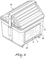
Figure 6 is a perspective view of a possible use of the exhibitor according to the invention. - With particular reference to the figures, the
reference numeral 1 generally designates an exhibitor for supporting informative material particularly for containers, urban furnishing elements and the like. - According to the invention, the
exhibitor 1 comprises at least oneplate 2 which is provided with drainage holes (which will be described and illustrated below) and with at least one contouredperimetric edge 3. -
Such plate 2 is intended to accommodate stably at least one panel 4. - The panel 4 is a rigid or semirigid support which bears the informative or advertising content to be exhibited. It can be made of plastic material, cardboard, plastic-coated card, aluminum or a combination of these materials.
- The
exhibitor 1, according to the invention, also comprises aclosure element 5 which is provided withmeans 6 for detachable coupling with the contouredperimetric edge 3. - The
closure element 5 couples the panel 4 to theplate 2. - The coupling means 6 and the contoured
perimetric edge 3 comprise respective mated and complementary profiles. - The
exhibitor 1 comprises at least twoplates perimetric edges - Advantageously the contoured
perimetric edge 3 and the coupling means 6 are constituted respectively by two mutually offset series ofprotrusions 7 and recesses 8. - Both of these
protrusions 7 and recesses 8 are substantially trapezoidal. - According to a particular embodiment, the two series of
protrusions 7 and recesses 8 are respectively arranged on two different planes which are parallel to the plane defined by theplate 2. - The staggered arrangement of the two series of
protrusions 7 and recesses 8 is such that eachprotrusion 7 of the first series is positioned at a recess of the second series, and vice versa. - In particular, the
protrusions 7 of theclosure element 5 and of the contouredperimetric edge 3 respectively have throughcavities 9 and openings 10 (specifically these throughcavities 9 andopenings 10 constitute part of the drainage holes). - In the coupling configuration of the
closure element 5 with the contouredperimetric edge 3 thecavities 9 are aligned with therespective openings 10 for the optional accommodation of corresponding locking means 11, which allow the mutual stable locking in this configuration. - Alternatively, a permanent locking can be envisaged, by way of adhesive bonding, on one side of the
exhibitor 1, and a temporary locking on the other side, in order to enable a quick replacement of the panel 4. - In order to prevent unauthorized persons from removing the
closure element 5 from theplate 2, one or more antitheft elements are moreover provided, such as for example a padlock or a screw with self-locking nut. - According to an embodiment of undoubted practical and applicative interest, the
exhibitor 1 comprises twoplates 2, (2a and 2b), and the protrusions 7 (in particular the protrusions designed to mutually connect 7a and 7b) of a contoured perimetric edge 4 (specifically the mutuallyopposite edges second plate openings - In the coupling configuration of the first and the second edge 3 (3a and 3b), the
openings 10a of thefirst plate 2a are aligned with the openings 11b of thesecond plate 2b, for the optional accommodation of corresponding locking means 11, which allow stable coupling in this configuration. - Alternatively, the mutual locking between the
plates - For this reason adapted recesses are provided in order to accommodate the adhesive or the silicone used for the locking.
- Conveniently the
plate 2 has at least one guidingportion 12 in order to facilitate the slideable insertion of at least one panel 4 on theplate 2 itself. - Such guiding
portion 12 has afirst part 13 which is integral with and perpendicular to theplate 2, and asecond part 14, which is integral with thefirst part 13 and arranged substantially parallel to theplate 2. - The different length of the
first part 13 of each guidingportion 12 determines the distance of the respective panel 4, accommodated thereon, from theplate 2. - At the area of the
plate 2 which is subtended by thesecond part 14 anoutflow passage 15 is arranged, so as to allow efficient draining of liquids (such passages 15 constitute part of the drainage holes) and the simultaneous outflow of dust and residues in general. - The guiding
portion 12 can be preferably U-shaped or V-shaped, but other embodiments are not ruled out. - In fact, according to a further embodiment of particular simplicity and effectiveness, the guiding
portion 12 can be a single, double or multiple track, for example E-shaped. - Such shape structure enables the simultaneous insertion of two or more panels 4, arranging them on different planes which are parallel to the
plate 2. - Such possibility makes it possible, for example, to insert a panel 4 with an advertising image and above this another two informative panels 4, smaller than the first, indicating the no-stopping sign and the type of refuse to discard in the container.
- The advertising panel 4, even if positioned below the two informative panels 4, is visible as well, since, the latter two being smaller in size, they only partially cover the surface of the advertising panel 4, which thus remains visible to the user.
- More specifically, at least one of the drainage holes, the through
cavities 9, theopenings 10 and thepassages 15 has respective identification markings for the selective accommodation of fixingelements 16 which make it possible to firmly couple theexhibitor 1 to therespective wall 17 of acontainer 18, urban furnishing element and the like. - Such identification markings make it possible for the operator to immediately and safely identify the best fixing points for each determined model of
container 18. - The possibility is not ruled out that the drainage holes, the through
cavities 9, theopenings 10 and thepassages 15 have different diameters so as to allow the use ofdifferent fixing elements 16 according to requirements. - Alternatively, the
exhibitor 1 can be firmly coupled to therespective wall 17 of acontainer 18, urban furnishing element and the like by adhesive bonding. - The characteristics of the locking means 11 and the fixing
elements 16 are such that they do not protrude forward, so as not to interfere with the sliding of the panel 4, or rearward, so as not to obstruct the correct positioning on the wall. - The
exhibitor 1 can comprise at least one component selected from a loudspeaker, at least one light source and at least one display screen, for the distribution of informative and/or advertising messages. - The light source can for example be used to notify the user of the status of the
container 18 i.e. a green light indicates that thecontainer 18 is operational and has space available to contain the refuse, whereas a red light indicates that thecontainer 18 is out of service because it is full. - The
exhibitor 1 also makes it possible to accommodate small loudspeakers for the aural diffusion of acoustic signals or synthesized voice. - The apparatuses for controlling and powering such components can be installed behind the
plate 2 by arrangement along a plane parallel thereto, or inside thecontainer 18 in a suitable portion thereof. - A graduated scale is arranged on the
plate 2 so as to facilitate the correct positioning and alignment of theexhibitor 1 on thewall 17. - Such scale is a sequence of equidistant lines, with distance graduation given in mm or cm and/or given in inches.
- The lines are distributed along a straight line and are numbered with increasing numerals.
- Such scale is generally positioned at the bottom on the left and it enables correct positioning by the operator with respect to the ground and/or with respect to a specific reference point arranged on the
container 18. - The possibility is not excluded of arranging the graduated scale in the
closure element 5 as well. - It must moreover be considered that the walls of the containers can have ribbing or reinforcement supports thus creating surfaces that are extremely uneven.
- For this reason, adapted shims can moreover be provided to be interposed between the
exhibitor 1 and thewall 17 of thecontainer 18. - The
plate 2 has a plurality of througheyelets 19 for optimum draining and the lightening thereof. - One or
more exhibitors 1 can be applied side by side, overlaid or with any other arrangement, to thewall 17 of acontainer 18, so that the black centering line remains visible. - Such line, which characterizes side-loading containers, is the line that enables the automatic emptying of the containers.
- In fact, by means of an adapted centering video camera, such line is read and codified by automatic robots, arranged on the collection vehicles, so as to identify the correct positioning, during the emptying step, of the collection vehicles with respect to the container.
- The
exhibitor 1 can be positioned with any orientation (horizontal, vertical, diagonal, inclined) along thewalls 17 or the cover of thecontainer 18. - The possibility is not excluded of also applying the
exhibitor 1 to other urban furnishing elements such as a post, or a wall. - Use of the
exhibitor 1 for supporting informative material particularly for containers, urban furnishing elements and the like according to the invention is as follows. - First, the shape and size of the
exhibitor 1 required are determined. - After this, one or
more plates 2 are assembled, until the final desired size is obtained. - The
plates 2, if there is more than one, are fixed to each other by adhesive bonding or by lockingmeans 11. - Then the operator proceeds by identifying the position of the
exhibitor 1 on thewall 17, optionally by using the graduated scale provided, and theexhibitor 1, without the closure element, is coupled, by means of the fixingelements 16 or adhesive bonding, to thewall 17 of thecontainer 18. - In this step the operator can thus choose the most suitable fixing points for that
specific container 18 using the respective identification markings without the need to make holes in theplate 2 or theexhibitor 1. - At this point the operator proceeds by inserting one or more panels 4, according to requirements, into the guiding
portions 12, after which theclosure element 5 is coupled to the contouredperimetric edge 3 by the locking means 11 or by adhesive bonding. - Thus it can be seen, from the foregoing description, that the
exhibitor 1, according to the invention, enables an easy and safe installation. - Effectively, the
exhibitor 1 for supporting informative material particularly for containers, urban furnishing elements and the like, according to the invention, also attains the high versatility required in that the modularity of theplates 2 makes it possible to freely compose it thus obtaining the desired final size, in relation to the size and to the shape structure of thecontainer 18. - Conveniently, the
exhibitor 1, according to the invention, is such as to enable a quick replacement of the informative material exhibited therein. - In fact it is sufficient to remove the
closure element 5 and take out the panel 4 to be replaced, insert the new panel 4 and reposition theclosure element 5. - Positively, the exhibitor according to the invention makes it possible to preserve the informative material exhibited therein from degradation.
- In particular the presence of the drainage holes, the through
cavities 9, theopenings 10, thepassages 15 and theeyelets 19 enables the expulsion of water, both rainwater and the water used to clean thecontainer 18. - It must also be considered that the plurality of through
eyelets 19 make it possible to reduce the weight of theexhibitor 1, thus facilitating the transport and installation thereof, as well as the quantity of material necessary to produce it with simultaneous reduction of costs. - The lower weight of the exhibitor also implies a lower weight of the
container 18, which is thus easier to shift and move both manually and by means of a mechanized lifting apparatus. - Moreover, the presence of guiding
portions 12, in particular the presence of thepassages 15, enable the expulsion of the dust deposited on theexhibitor 1. - Profitably, during the step of extracting a panel 4 and subsequently introducing another panel 4, the dust is shifted until it naturally exits from the
passages 15 arranged at the rear of the guidingportions 12. - In practice it has been found that the
exhibitor 1 for supporting informative material particularly for containers, urban furnishing elements and the like fully achieves the set aim in that it ensures considerable versatility of use, thanks to the modularity that distinguishes it. - The invention, thus conceived, is susceptible of numerous modifications and variations, all of which are within the scope of the appended claims. Moreover, all the details may be substituted by other, technically equivalent elements.
- In the embodiments illustrated, individual characteristics shown in relation to specific examples may in reality be interchanged with other, different characteristics, existing in other embodiments.
- In practice, the materials employed, as well as the dimensions, may be any according to requirements and to the state of the art.
- The disclosures in Italian Patent Application No.
BO2011A000629 - Where technical features mentioned in any claim are followed by reference signs, those reference signs have been included for the sole purpose of increasing the intelligibility of the claims and accordingly, such reference signs do not have any limiting effect on the interpretation of each element identified by way of example by such reference signs.
Claims (11)
- An exhibiting device for supporting informative material, particularly for containers, urban furnishing elements and the like, whereby it comprises at least one plate (2), which is provided with at least one contoured perimetric edge (3), said plate (2) being intended to accommodate stably at least one panel (4), and at least one closure element (5) provided with means (6) for detachable coupling to said contoured perimetric edge (3), said closure element (5) coupling said panel (4) to said plate (2), said coupling means (6) and said contoured perimetric edge (3) comprising respective mated and complementary profiles, said exhibiting device being characterized in that the at least one plate is provided with drainage holes and in that it comprises at least two plates (2, 2a and 2b), which are mutually connected by means of the mutual juxtaposition of said mated and complementary profiles of the contoured perimetric edges (3, 3a and 3b) of said plates.
- The exhibiting device according to claim 1, characterized in that said contoured perimetric edge (3) and said coupling means (6) are constituted respectively by two mutually offset series of protrusions (7) and recesses (8), said protrusions (7) and said recesses (8) being substantially trapezoidal.
- The exhibiting device according to claim 2, characterized in that the protrusions (7) of said closure element (5) and said contoured perimetric edge (3) respectively have through cavities (9) and openings (10), in the configuration for the coupling of the closure element (6) with the contoured perimetric edge (4) said cavities (10) being aligned with respective openings (10) for the optional accommodation of corresponding locking means (11), allowing mutual stable locking in said configuration.
- The exhibiting device according to one or more of the preceding claims, characterized in that it comprises two plates (2, 2a and 2b), the protrusions (8) of a contoured perimetric edge (4, 4a and 4b) of a first plate and of a second plate (2, 2a and 2b) having a plurality of openings (10), in the coupling configuration of said first and second edges (4) the openings (10a) of said first plate (2a) being aligned with the openings of said second plate (2b) for the optional accommodation of corresponding locking means (11), allowing stable coupling in said configuration.
- The exhibiting device according to one or more of the preceding claims, characterized in that said plate (2) has at least one guiding portion (12) so as to facilitate the slideable insertion of said at least one panel (4) on said plate (2).
- The exhibiting device according to one or more of the preceding claims, characterized in that said guiding portion (12) has a first part (13), which is integral with and perpendicular to said plate (2), and a second part (14), which is integral with said first part (13) and arranged substantially parallel to said plate (2), the different length of the first part (13) of each guiding portion (12) determining the distance of the respective panel (4), accommodated thereon, from the plate (2).
- The exhibiting device according to one or more of the preceding claims, characterized in that an outflow passage (15) is arranged at the area of said plate (2) that is subtended by said second part (14) so as to allow efficient draining of liquids and the simultaneous escape of dust and residues in general.
- The exhibiting device according to one or more of the preceding claims, characterized in that at least one among said drainage holes, said openings (10) and said passages (15) has respective identification markings for the selective accommodation of fixing elements (16) which are adapted to firmly couple said exhibiting device (1) to the respective wall (17) of a container (18), urban furnishing element and the like.
- The exhibiting device according to one or more of the preceding claims, characterized in that it comprises at least one component selected from a loudspeaker, at least one light source and at least one display screen, for the distribution of informative or advertising messages.
- The exhibiting device according to one or more of the preceding claims, characterized in that a graduated scale is provided on said plate (2) and is adapted to facilitate the correct positioning and alignment of said exhibiting device (1) on said wall (17).
- The exhibiting device according to one or more of the preceding claims, characterized in that said plate has a plurality of through eyelets (19) for optimum draining and for the lightening thereof.
Priority Applications (1)
| Application Number | Priority Date | Filing Date | Title |
|---|---|---|---|
| SI201231152T SI2777036T1 (en) | 2011-11-07 | 2012-10-19 | Exhibiting device for supporting informative material particularly for containers, urban furnishing elements and the like |
Applications Claiming Priority (2)
| Application Number | Priority Date | Filing Date | Title |
|---|---|---|---|
| IT000629A ITBO20110629A1 (en) | 2011-11-07 | 2011-11-07 | EXHIBITOR FOR THE SUPPORT OF INFORMATION MATERIALS PARTICULARLY FOR CONTAINERS, URBAN AND SIMILAR FURNISHING ELEMENTS. |
| PCT/EP2012/070745 WO2013068225A1 (en) | 2011-11-07 | 2012-10-19 | Exhibitor for supporting informative material particularly for containers, urban furnishing elements and the like |
Publications (2)
| Publication Number | Publication Date |
|---|---|
| EP2777036A1 EP2777036A1 (en) | 2014-09-17 |
| EP2777036B1 true EP2777036B1 (en) | 2017-09-13 |
Family
ID=45094064
Family Applications (1)
| Application Number | Title | Priority Date | Filing Date |
|---|---|---|---|
| EP12777901.5A Active EP2777036B1 (en) | 2011-11-07 | 2012-10-19 | Exhibiting device for supporting informative material particularly for containers, urban furnishing elements and the like |
Country Status (5)
| Country | Link |
|---|---|
| EP (1) | EP2777036B1 (en) |
| ES (1) | ES2651217T3 (en) |
| IT (1) | ITBO20110629A1 (en) |
| SI (1) | SI2777036T1 (en) |
| WO (1) | WO2013068225A1 (en) |
Family Cites Families (4)
| Publication number | Priority date | Publication date | Assignee | Title |
|---|---|---|---|---|
| DE4226253A1 (en) * | 1992-08-08 | 1994-02-10 | Loebbert Franz Josef | Protective cover for refuse container - provides outer display surface round container to protect against damage and allow labelling. |
| EP1228727A1 (en) * | 2001-01-15 | 2002-08-07 | Gianbattista Maggiori | Document display |
| US20030146221A1 (en) * | 2001-12-10 | 2003-08-07 | Lauer Robert W. | Waste container assembly and modular product system |
| GB2454707A (en) * | 2007-11-15 | 2009-05-20 | Julian Andrews | Sign for waste container |
-
2011
- 2011-11-07 IT IT000629A patent/ITBO20110629A1/en unknown
-
2012
- 2012-10-19 ES ES12777901.5T patent/ES2651217T3/en active Active
- 2012-10-19 WO PCT/EP2012/070745 patent/WO2013068225A1/en not_active Ceased
- 2012-10-19 EP EP12777901.5A patent/EP2777036B1/en active Active
- 2012-10-19 SI SI201231152T patent/SI2777036T1/en unknown
Also Published As
| Publication number | Publication date |
|---|---|
| ES2651217T3 (en) | 2018-01-25 |
| WO2013068225A1 (en) | 2013-05-16 |
| EP2777036A1 (en) | 2014-09-17 |
| SI2777036T1 (en) | 2018-01-31 |
| ITBO20110629A1 (en) | 2013-05-08 |
Similar Documents
| Publication | Publication Date | Title |
|---|---|---|
| US3947985A (en) | Combined trash receptacle and advertising medium | |
| EP2777036B1 (en) | Exhibiting device for supporting informative material particularly for containers, urban furnishing elements and the like | |
| US10160596B2 (en) | Refuse container support apparatus | |
| EP3636561B1 (en) | Device for separate collection of waste | |
| KR20160032736A (en) | Separate collection system for household waste communal management | |
| CN210368707U (en) | Road sign convenient for changing road sign content | |
| KR101254585B1 (en) | Apparatus of displaying road work for fall prevention | |
| KR101712058B1 (en) | Attached separated bins | |
| KR20160048368A (en) | Capable of selectively binding and separating billboard | |
| CN210515959U (en) | anti-theft sign | |
| CN223433747U (en) | Road construction warning sign | |
| CA2284421C (en) | Advertising structure for a pole | |
| GB2269040A (en) | Safety sign. | |
| EP2364900A2 (en) | Cycle stand | |
| RU152262U1 (en) | DEMO RACK ON WHEELS | |
| CN216339985U (en) | Town road oozes row structure | |
| CN214608624U (en) | Packing box convenient to dismantle and retrieve | |
| CN217227629U (en) | Novel engine protection plate arranging and placing device | |
| CN213836388U (en) | Convenient fixed instruction road sign is used in rail transit transfer | |
| RU47129U1 (en) | MOBILE ADVERTISING | |
| CN216139980U (en) | Passenger transport guiding device for railway platform | |
| WO2013178590A1 (en) | Covering particularly for containers, urban furnishing elements and the like | |
| AU2007247035B2 (en) | Information display device | |
| KR200285472Y1 (en) | foldable signpost for construction site | |
| KR200483560Y1 (en) | A guidepost |
Legal Events
| Date | Code | Title | Description |
|---|---|---|---|
| PUAI | Public reference made under article 153(3) epc to a published international application that has entered the european phase |
Free format text: ORIGINAL CODE: 0009012 |
|
| 17P | Request for examination filed |
Effective date: 20140604 |
|
| AK | Designated contracting states |
Kind code of ref document: A1 Designated state(s): AL AT BE BG CH CY CZ DE DK EE ES FI FR GB GR HR HU IE IS IT LI LT LU LV MC MK MT NL NO PL PT RO RS SE SI SK SM TR |
|
| DAX | Request for extension of the european patent (deleted) | ||
| GRAP | Despatch of communication of intention to grant a patent |
Free format text: ORIGINAL CODE: EPIDOSNIGR1 |
|
| STAA | Information on the status of an ep patent application or granted ep patent |
Free format text: STATUS: GRANT OF PATENT IS INTENDED |
|
| INTG | Intention to grant announced |
Effective date: 20161121 |
|
| GRAS | Grant fee paid |
Free format text: ORIGINAL CODE: EPIDOSNIGR3 |
|
| GRAA | (expected) grant |
Free format text: ORIGINAL CODE: 0009210 |
|
| STAA | Information on the status of an ep patent application or granted ep patent |
Free format text: STATUS: THE PATENT HAS BEEN GRANTED |
|
| AK | Designated contracting states |
Kind code of ref document: B1 Designated state(s): AL AT BE BG CH CY CZ DE DK EE ES FI FR GB GR HR HU IE IS IT LI LT LU LV MC MK MT NL NO PL PT RO RS SE SI SK SM TR |
|
| REG | Reference to a national code |
Ref country code: GB Ref legal event code: FG4D |
|
| REG | Reference to a national code |
Ref country code: CH Ref legal event code: EP |
|
| REG | Reference to a national code |
Ref country code: IE Ref legal event code: FG4D |
|
| REG | Reference to a national code |
Ref country code: FR Ref legal event code: PLFP Year of fee payment: 6 |
|
| REG | Reference to a national code |
Ref country code: AT Ref legal event code: REF Ref document number: 928852 Country of ref document: AT Kind code of ref document: T Effective date: 20171015 |
|
| REG | Reference to a national code |
Ref country code: DE Ref legal event code: R096 Ref document number: 602012037334 Country of ref document: DE |
|
| REG | Reference to a national code |
Ref country code: NL Ref legal event code: MP Effective date: 20170913 |
|
| REG | Reference to a national code |
Ref country code: ES Ref legal event code: FG2A Ref document number: 2651217 Country of ref document: ES Kind code of ref document: T3 Effective date: 20180125 Ref country code: LT Ref legal event code: MG4D |
|
| PG25 | Lapsed in a contracting state [announced via postgrant information from national office to epo] |
Ref country code: FI Free format text: LAPSE BECAUSE OF FAILURE TO SUBMIT A TRANSLATION OF THE DESCRIPTION OR TO PAY THE FEE WITHIN THE PRESCRIBED TIME-LIMIT Effective date: 20170913 Ref country code: LT Free format text: LAPSE BECAUSE OF FAILURE TO SUBMIT A TRANSLATION OF THE DESCRIPTION OR TO PAY THE FEE WITHIN THE PRESCRIBED TIME-LIMIT Effective date: 20170913 Ref country code: HR Free format text: LAPSE BECAUSE OF FAILURE TO SUBMIT A TRANSLATION OF THE DESCRIPTION OR TO PAY THE FEE WITHIN THE PRESCRIBED TIME-LIMIT Effective date: 20170913 Ref country code: SE Free format text: LAPSE BECAUSE OF FAILURE TO SUBMIT A TRANSLATION OF THE DESCRIPTION OR TO PAY THE FEE WITHIN THE PRESCRIBED TIME-LIMIT Effective date: 20170913 Ref country code: NO Free format text: LAPSE BECAUSE OF FAILURE TO SUBMIT A TRANSLATION OF THE DESCRIPTION OR TO PAY THE FEE WITHIN THE PRESCRIBED TIME-LIMIT Effective date: 20171213 |
|
| REG | Reference to a national code |
Ref country code: AT Ref legal event code: MK05 Ref document number: 928852 Country of ref document: AT Kind code of ref document: T Effective date: 20170913 |
|
| PG25 | Lapsed in a contracting state [announced via postgrant information from national office to epo] |
Ref country code: GR Free format text: LAPSE BECAUSE OF FAILURE TO SUBMIT A TRANSLATION OF THE DESCRIPTION OR TO PAY THE FEE WITHIN THE PRESCRIBED TIME-LIMIT Effective date: 20171214 Ref country code: LV Free format text: LAPSE BECAUSE OF FAILURE TO SUBMIT A TRANSLATION OF THE DESCRIPTION OR TO PAY THE FEE WITHIN THE PRESCRIBED TIME-LIMIT Effective date: 20170913 Ref country code: BG Free format text: LAPSE BECAUSE OF FAILURE TO SUBMIT A TRANSLATION OF THE DESCRIPTION OR TO PAY THE FEE WITHIN THE PRESCRIBED TIME-LIMIT Effective date: 20171213 Ref country code: RS Free format text: LAPSE BECAUSE OF FAILURE TO SUBMIT A TRANSLATION OF THE DESCRIPTION OR TO PAY THE FEE WITHIN THE PRESCRIBED TIME-LIMIT Effective date: 20170913 |
|
| PG25 | Lapsed in a contracting state [announced via postgrant information from national office to epo] |
Ref country code: NL Free format text: LAPSE BECAUSE OF FAILURE TO SUBMIT A TRANSLATION OF THE DESCRIPTION OR TO PAY THE FEE WITHIN THE PRESCRIBED TIME-LIMIT Effective date: 20170913 |
|
| REG | Reference to a national code |
Ref country code: DE Ref legal event code: R082 Ref document number: 602012037334 Country of ref document: DE Representative=s name: SCHIEBER - FARAGO PATENTANWAELTE, DE Ref country code: DE Ref legal event code: R082 Ref document number: 602012037334 Country of ref document: DE Representative=s name: FARAGO PATENTANWALTSGESELLSCHAFT MBH, DE Ref country code: DE Ref legal event code: R082 Ref document number: 602012037334 Country of ref document: DE Representative=s name: FARAGO PATENTANWALTS- UND RECHTSANWALTSGESELLS, DE Ref country code: DE Ref legal event code: R082 Ref document number: 602012037334 Country of ref document: DE Representative=s name: FARAGO PATENTANWAELTE, DE |
|
| PG25 | Lapsed in a contracting state [announced via postgrant information from national office to epo] |
Ref country code: PL Free format text: LAPSE BECAUSE OF FAILURE TO SUBMIT A TRANSLATION OF THE DESCRIPTION OR TO PAY THE FEE WITHIN THE PRESCRIBED TIME-LIMIT Effective date: 20170913 Ref country code: CZ Free format text: LAPSE BECAUSE OF FAILURE TO SUBMIT A TRANSLATION OF THE DESCRIPTION OR TO PAY THE FEE WITHIN THE PRESCRIBED TIME-LIMIT Effective date: 20170913 Ref country code: RO Free format text: LAPSE BECAUSE OF FAILURE TO SUBMIT A TRANSLATION OF THE DESCRIPTION OR TO PAY THE FEE WITHIN THE PRESCRIBED TIME-LIMIT Effective date: 20170913 |
|
| PG25 | Lapsed in a contracting state [announced via postgrant information from national office to epo] |
Ref country code: EE Free format text: LAPSE BECAUSE OF FAILURE TO SUBMIT A TRANSLATION OF THE DESCRIPTION OR TO PAY THE FEE WITHIN THE PRESCRIBED TIME-LIMIT Effective date: 20170913 Ref country code: SM Free format text: LAPSE BECAUSE OF FAILURE TO SUBMIT A TRANSLATION OF THE DESCRIPTION OR TO PAY THE FEE WITHIN THE PRESCRIBED TIME-LIMIT Effective date: 20170913 Ref country code: SK Free format text: LAPSE BECAUSE OF FAILURE TO SUBMIT A TRANSLATION OF THE DESCRIPTION OR TO PAY THE FEE WITHIN THE PRESCRIBED TIME-LIMIT Effective date: 20170913 Ref country code: IS Free format text: LAPSE BECAUSE OF FAILURE TO SUBMIT A TRANSLATION OF THE DESCRIPTION OR TO PAY THE FEE WITHIN THE PRESCRIBED TIME-LIMIT Effective date: 20180113 Ref country code: AT Free format text: LAPSE BECAUSE OF FAILURE TO SUBMIT A TRANSLATION OF THE DESCRIPTION OR TO PAY THE FEE WITHIN THE PRESCRIBED TIME-LIMIT Effective date: 20170913 |
|
| REG | Reference to a national code |
Ref country code: CH Ref legal event code: PL |
|
| REG | Reference to a national code |
Ref country code: DE Ref legal event code: R097 Ref document number: 602012037334 Country of ref document: DE |
|
| PG25 | Lapsed in a contracting state [announced via postgrant information from national office to epo] |
Ref country code: MC Free format text: LAPSE BECAUSE OF FAILURE TO SUBMIT A TRANSLATION OF THE DESCRIPTION OR TO PAY THE FEE WITHIN THE PRESCRIBED TIME-LIMIT Effective date: 20170913 |
|
| PLBE | No opposition filed within time limit |
Free format text: ORIGINAL CODE: 0009261 |
|
| STAA | Information on the status of an ep patent application or granted ep patent |
Free format text: STATUS: NO OPPOSITION FILED WITHIN TIME LIMIT |
|
| REG | Reference to a national code |
Ref country code: IE Ref legal event code: MM4A |
|
| PG25 | Lapsed in a contracting state [announced via postgrant information from national office to epo] |
Ref country code: CH Free format text: LAPSE BECAUSE OF NON-PAYMENT OF DUE FEES Effective date: 20171031 Ref country code: LU Free format text: LAPSE BECAUSE OF NON-PAYMENT OF DUE FEES Effective date: 20171019 Ref country code: LI Free format text: LAPSE BECAUSE OF NON-PAYMENT OF DUE FEES Effective date: 20171031 Ref country code: DK Free format text: LAPSE BECAUSE OF FAILURE TO SUBMIT A TRANSLATION OF THE DESCRIPTION OR TO PAY THE FEE WITHIN THE PRESCRIBED TIME-LIMIT Effective date: 20170913 |
|
| 26N | No opposition filed |
Effective date: 20180614 |
|
| REG | Reference to a national code |
Ref country code: BE Ref legal event code: MM Effective date: 20171031 |
|
| PG25 | Lapsed in a contracting state [announced via postgrant information from national office to epo] |
Ref country code: BE Free format text: LAPSE BECAUSE OF NON-PAYMENT OF DUE FEES Effective date: 20171031 |
|
| PG25 | Lapsed in a contracting state [announced via postgrant information from national office to epo] |
Ref country code: MT Free format text: LAPSE BECAUSE OF NON-PAYMENT OF DUE FEES Effective date: 20171019 |
|
| REG | Reference to a national code |
Ref country code: FR Ref legal event code: PLFP Year of fee payment: 7 |
|
| PG25 | Lapsed in a contracting state [announced via postgrant information from national office to epo] |
Ref country code: IE Free format text: LAPSE BECAUSE OF NON-PAYMENT OF DUE FEES Effective date: 20171019 |
|
| PG25 | Lapsed in a contracting state [announced via postgrant information from national office to epo] |
Ref country code: HU Free format text: LAPSE BECAUSE OF FAILURE TO SUBMIT A TRANSLATION OF THE DESCRIPTION OR TO PAY THE FEE WITHIN THE PRESCRIBED TIME-LIMIT; INVALID AB INITIO Effective date: 20121019 |
|
| PG25 | Lapsed in a contracting state [announced via postgrant information from national office to epo] |
Ref country code: CY Free format text: LAPSE BECAUSE OF NON-PAYMENT OF DUE FEES Effective date: 20170913 |
|
| PG25 | Lapsed in a contracting state [announced via postgrant information from national office to epo] |
Ref country code: MK Free format text: LAPSE BECAUSE OF FAILURE TO SUBMIT A TRANSLATION OF THE DESCRIPTION OR TO PAY THE FEE WITHIN THE PRESCRIBED TIME-LIMIT Effective date: 20170913 |
|
| PG25 | Lapsed in a contracting state [announced via postgrant information from national office to epo] |
Ref country code: TR Free format text: LAPSE BECAUSE OF FAILURE TO SUBMIT A TRANSLATION OF THE DESCRIPTION OR TO PAY THE FEE WITHIN THE PRESCRIBED TIME-LIMIT Effective date: 20170913 |
|
| PG25 | Lapsed in a contracting state [announced via postgrant information from national office to epo] |
Ref country code: PT Free format text: LAPSE BECAUSE OF FAILURE TO SUBMIT A TRANSLATION OF THE DESCRIPTION OR TO PAY THE FEE WITHIN THE PRESCRIBED TIME-LIMIT Effective date: 20170913 |
|
| PG25 | Lapsed in a contracting state [announced via postgrant information from national office to epo] |
Ref country code: AL Free format text: LAPSE BECAUSE OF FAILURE TO SUBMIT A TRANSLATION OF THE DESCRIPTION OR TO PAY THE FEE WITHIN THE PRESCRIBED TIME-LIMIT Effective date: 20170913 |
|
| PGFP | Annual fee paid to national office [announced via postgrant information from national office to epo] |
Ref country code: GB Payment date: 20211026 Year of fee payment: 10 Ref country code: DE Payment date: 20211027 Year of fee payment: 10 |
|
| PGFP | Annual fee paid to national office [announced via postgrant information from national office to epo] |
Ref country code: SI Payment date: 20210929 Year of fee payment: 10 |
|
| REG | Reference to a national code |
Ref country code: DE Ref legal event code: R082 Ref document number: 602012037334 Country of ref document: DE Representative=s name: SCHIEBER - FARAGO PATENTANWAELTE, DE Ref country code: DE Ref legal event code: R082 Ref document number: 602012037334 Country of ref document: DE Representative=s name: FARAGO PATENTANWALTSGESELLSCHAFT MBH, DE |
|
| REG | Reference to a national code |
Ref country code: DE Ref legal event code: R082 Ref document number: 602012037334 Country of ref document: DE Representative=s name: SCHIEBER - FARAGO PATENTANWAELTE, DE |
|
| REG | Reference to a national code |
Ref country code: DE Ref legal event code: R119 Ref document number: 602012037334 Country of ref document: DE |
|
| GBPC | Gb: european patent ceased through non-payment of renewal fee |
Effective date: 20221019 |
|
| PG25 | Lapsed in a contracting state [announced via postgrant information from national office to epo] |
Ref country code: DE Free format text: LAPSE BECAUSE OF NON-PAYMENT OF DUE FEES Effective date: 20230503 |
|
| REG | Reference to a national code |
Ref country code: SI Ref legal event code: KO00 Effective date: 20230629 |
|
| PG25 | Lapsed in a contracting state [announced via postgrant information from national office to epo] |
Ref country code: SI Free format text: LAPSE BECAUSE OF NON-PAYMENT OF DUE FEES Effective date: 20221020 |
|
| P01 | Opt-out of the competence of the unified patent court (upc) registered |
Effective date: 20230915 |
|
| PG25 | Lapsed in a contracting state [announced via postgrant information from national office to epo] |
Ref country code: GB Free format text: LAPSE BECAUSE OF NON-PAYMENT OF DUE FEES Effective date: 20221019 |
|
| PGFP | Annual fee paid to national office [announced via postgrant information from national office to epo] |
Ref country code: ES Payment date: 20241118 Year of fee payment: 13 |
|
| PGFP | Annual fee paid to national office [announced via postgrant information from national office to epo] |
Ref country code: IT Payment date: 20251028 Year of fee payment: 14 |
|
| PGFP | Annual fee paid to national office [announced via postgrant information from national office to epo] |
Ref country code: FR Payment date: 20251027 Year of fee payment: 14 |