EP2776775B1 - Air-to-air atmospheric exchanger - Google Patents
Air-to-air atmospheric exchanger Download PDFInfo
- Publication number
- EP2776775B1 EP2776775B1 EP12847681.9A EP12847681A EP2776775B1 EP 2776775 B1 EP2776775 B1 EP 2776775B1 EP 12847681 A EP12847681 A EP 12847681A EP 2776775 B1 EP2776775 B1 EP 2776775B1
- Authority
- EP
- European Patent Office
- Prior art keywords
- sheet
- rib
- ribs
- axis
- horizontal
- Prior art date
- Legal status (The legal status is an assumption and is not a legal conclusion. Google has not performed a legal analysis and makes no representation as to the accuracy of the status listed.)
- Active
Links
Images



Classifications
-
- F—MECHANICAL ENGINEERING; LIGHTING; HEATING; WEAPONS; BLASTING
- F28—HEAT EXCHANGE IN GENERAL
- F28B—STEAM OR VAPOUR CONDENSERS
- F28B1/00—Condensers in which the steam or vapour is separate from the cooling medium by walls, e.g. surface condenser
- F28B1/06—Condensers in which the steam or vapour is separate from the cooling medium by walls, e.g. surface condenser using air or other gas as the cooling medium
-
- F—MECHANICAL ENGINEERING; LIGHTING; HEATING; WEAPONS; BLASTING
- F28—HEAT EXCHANGE IN GENERAL
- F28F—DETAILS OF HEAT-EXCHANGE AND HEAT-TRANSFER APPARATUS, OF GENERAL APPLICATION
- F28F13/00—Arrangements for modifying heat-transfer, e.g. increasing, decreasing
- F28F13/06—Arrangements for modifying heat-transfer, e.g. increasing, decreasing by affecting the pattern of flow of the heat-exchange media
- F28F13/12—Arrangements for modifying heat-transfer, e.g. increasing, decreasing by affecting the pattern of flow of the heat-exchange media by creating turbulence, e.g. by stirring, by increasing the force of circulation
-
- F—MECHANICAL ENGINEERING; LIGHTING; HEATING; WEAPONS; BLASTING
- F28—HEAT EXCHANGE IN GENERAL
- F28C—HEAT-EXCHANGE APPARATUS, NOT PROVIDED FOR IN ANOTHER SUBCLASS, IN WHICH THE HEAT-EXCHANGE MEDIA COME INTO DIRECT CONTACT WITHOUT CHEMICAL INTERACTION
- F28C1/00—Direct-contact trickle coolers, e.g. cooling towers
- F28C1/14—Direct-contact trickle coolers, e.g. cooling towers comprising also a non-direct contact heat exchange
-
- F—MECHANICAL ENGINEERING; LIGHTING; HEATING; WEAPONS; BLASTING
- F28—HEAT EXCHANGE IN GENERAL
- F28D—HEAT-EXCHANGE APPARATUS, NOT PROVIDED FOR IN ANOTHER SUBCLASS, IN WHICH THE HEAT-EXCHANGE MEDIA DO NOT COME INTO DIRECT CONTACT
- F28D15/00—Heat-exchange apparatus with the intermediate heat-transfer medium in closed tubes passing into or through the conduit walls ; Heat-exchange apparatus employing intermediate heat-transfer medium or bodies
-
- F—MECHANICAL ENGINEERING; LIGHTING; HEATING; WEAPONS; BLASTING
- F28—HEAT EXCHANGE IN GENERAL
- F28D—HEAT-EXCHANGE APPARATUS, NOT PROVIDED FOR IN ANOTHER SUBCLASS, IN WHICH THE HEAT-EXCHANGE MEDIA DO NOT COME INTO DIRECT CONTACT
- F28D9/00—Heat-exchange apparatus having stationary plate-like or laminated conduit assemblies for both heat-exchange media, the media being in contact with different sides of a conduit wall
- F28D9/0031—Heat-exchange apparatus having stationary plate-like or laminated conduit assemblies for both heat-exchange media, the media being in contact with different sides of a conduit wall the conduits for one heat-exchange medium being formed by paired plates touching each other
- F28D9/0037—Heat-exchange apparatus having stationary plate-like or laminated conduit assemblies for both heat-exchange media, the media being in contact with different sides of a conduit wall the conduits for one heat-exchange medium being formed by paired plates touching each other the conduits for the other heat-exchange medium also being formed by paired plates touching each other
-
- F—MECHANICAL ENGINEERING; LIGHTING; HEATING; WEAPONS; BLASTING
- F28—HEAT EXCHANGE IN GENERAL
- F28F—DETAILS OF HEAT-EXCHANGE AND HEAT-TRANSFER APPARATUS, OF GENERAL APPLICATION
- F28F25/00—Component parts of trickle coolers
- F28F25/02—Component parts of trickle coolers for distributing, circulating, and accumulating liquid
- F28F25/08—Splashing boards or grids, e.g. for converting liquid sprays into liquid films; Elements or beds for increasing the area of the contact surface
- F28F25/087—Vertical or inclined sheets; Supports or spacers
-
- F—MECHANICAL ENGINEERING; LIGHTING; HEATING; WEAPONS; BLASTING
- F28—HEAT EXCHANGE IN GENERAL
- F28F—DETAILS OF HEAT-EXCHANGE AND HEAT-TRANSFER APPARATUS, OF GENERAL APPLICATION
- F28F3/00—Plate-like or laminated elements; Assemblies of plate-like or laminated elements
- F28F3/02—Elements or assemblies thereof with means for increasing heat-transfer area, e.g. with fins, with recesses, with corrugations
- F28F3/04—Elements or assemblies thereof with means for increasing heat-transfer area, e.g. with fins, with recesses, with corrugations the means being integral with the element
- F28F3/042—Elements or assemblies thereof with means for increasing heat-transfer area, e.g. with fins, with recesses, with corrugations the means being integral with the element in the form of local deformations of the element
- F28F3/046—Elements or assemblies thereof with means for increasing heat-transfer area, e.g. with fins, with recesses, with corrugations the means being integral with the element in the form of local deformations of the element the deformations being linear, e.g. corrugations
-
- F—MECHANICAL ENGINEERING; LIGHTING; HEATING; WEAPONS; BLASTING
- F28—HEAT EXCHANGE IN GENERAL
- F28F—DETAILS OF HEAT-EXCHANGE AND HEAT-TRANSFER APPARATUS, OF GENERAL APPLICATION
- F28F9/00—Casings; Header boxes; Auxiliary supports for elements; Auxiliary members within casings
- F28F9/007—Auxiliary supports for elements
- F28F9/0075—Supports for plates or plate assemblies
-
- F—MECHANICAL ENGINEERING; LIGHTING; HEATING; WEAPONS; BLASTING
- F28—HEAT EXCHANGE IN GENERAL
- F28C—HEAT-EXCHANGE APPARATUS, NOT PROVIDED FOR IN ANOTHER SUBCLASS, IN WHICH THE HEAT-EXCHANGE MEDIA COME INTO DIRECT CONTACT WITHOUT CHEMICAL INTERACTION
- F28C1/00—Direct-contact trickle coolers, e.g. cooling towers
- F28C1/14—Direct-contact trickle coolers, e.g. cooling towers comprising also a non-direct contact heat exchange
- F28C2001/145—Direct-contact trickle coolers, e.g. cooling towers comprising also a non-direct contact heat exchange with arrangements of adjacent wet and dry passages
-
- Y—GENERAL TAGGING OF NEW TECHNOLOGICAL DEVELOPMENTS; GENERAL TAGGING OF CROSS-SECTIONAL TECHNOLOGIES SPANNING OVER SEVERAL SECTIONS OF THE IPC; TECHNICAL SUBJECTS COVERED BY FORMER USPC CROSS-REFERENCE ART COLLECTIONS [XRACs] AND DIGESTS
- Y02—TECHNOLOGIES OR APPLICATIONS FOR MITIGATION OR ADAPTATION AGAINST CLIMATE CHANGE
- Y02B—CLIMATE CHANGE MITIGATION TECHNOLOGIES RELATED TO BUILDINGS, e.g. HOUSING, HOUSE APPLIANCES OR RELATED END-USER APPLICATIONS
- Y02B30/00—Energy efficient heating, ventilation or air conditioning [HVAC]
- Y02B30/70—Efficient control or regulation technologies, e.g. for control of refrigerant flow, motor or heating
-
- Y—GENERAL TAGGING OF NEW TECHNOLOGICAL DEVELOPMENTS; GENERAL TAGGING OF CROSS-SECTIONAL TECHNOLOGIES SPANNING OVER SEVERAL SECTIONS OF THE IPC; TECHNICAL SUBJECTS COVERED BY FORMER USPC CROSS-REFERENCE ART COLLECTIONS [XRACs] AND DIGESTS
- Y10—TECHNICAL SUBJECTS COVERED BY FORMER USPC
- Y10S—TECHNICAL SUBJECTS COVERED BY FORMER USPC CROSS-REFERENCE ART COLLECTIONS [XRACs] AND DIGESTS
- Y10S261/00—Gas and liquid contact apparatus
- Y10S261/11—Cooling towers
Definitions
- the present invention relates generally to the reduction of cooling tower plume and/or water reclamation from cooling tower effluent or other heat rejection devices. More particularly, the present invention relates to method and apparatus for reducing the cooling tower plume and/or reclaiming water from cooling tower effluent to provide a source of clean water and reduce water consumption of the cooling tower.
- the documents US 7328886 B2 and EP 0982427 A1 disclose a fill pack having the features in the preamble of claim 1.
- cooling towers In both of the foregoing processes, and numerous other processes that require the step of dissipating excess heat, cooling towers have been employed.
- wet type cooling towers water is pumped passed a condenser coil containing the heated steam, refrigerant, or other heated liquid or gas, thereby transferring heat into the water.
- the water is then pumped to the cooling tower and sprayed over a cooling tower media comprised of thin sheets of material or splash bars.
- ambient air is forced passed the heated water and heat is transmitted from the water to the air by both sensible and evaporative heat transfer.
- the air is then forced out of the cooling tower and dissipated into the surrounding air.
- Cooling towers are highly efficient and cost effective means of dissipating this excess heat and thus are widely used for this purpose.
- a common drawback to cooling towers is that under certain atmospheric conditions a plume can be created by moisture from the heated water source evaporating into the air stream being carried out of the top of the cooling tower.
- the plume can cause low lying fog in the vicinity of the cooling tower.
- the plume can also cause icing on roads in the vicinity of the cooling tower where colder temperatures cause the moisture in the plume to freeze.
- plume abated cooling tower in which ambient air, in addition to being brought in at the bottom of the tower and forced upwards through a fill pack as hot water is sprayed down on the fill pack, is brought into the cooling tower through isolated heat conductive passageways below the hot water spray heads. These passageways which are made from a heat conductive material such as aluminum, copper, etc., allow the ambient air to absorb some of the heat without moisture being evaporated into the air. At the top of the tower the wet laden heated air and the dry heated air are mixed thereby reducing the plume.
- Another example includes a plume prevention system in which the hot water is partially cooled before being provided to the cooling tower.
- the partial cooling of the hot water is performed using a separate heat exchanger operating with a separate cooling medium such as air or water.
- the separate heat exchanger reduces the efficiency of the cooling tower and thus should only be employed when atmospheric conditions exist in which a plume would be created by the cooling tower.
- a system may be employed where hot water is first pumped through a dry air cooling section where air is forced across heat exchange fins connected to the flow. The water, which has been partially cooled, is then sprayed over a fill pack positioned below the dry air cooling section and air is forced through the fill pack to further cool the water. The wet air is then forced upwards within the tower and mixed with the heated dry air from the dry cooling process and forced out the top of the tower.
- US Patent Number 7 328 886 describes a air-to-air atmospheric heat exchanger for condensing cooling tower effluent, comprising sheets having horizontal and vertical ribs so as to define a first flow path through the sheets and a second flow path over anf under the sheets.
- European Patent Application EP 0 982 427 describes a counterflow heat exchanger for a clothes dryer, comprising superimposed sheets forming air channels having ribs, the ribs between two neighbouring plates forming an air channel.
- US Patent Number 3 931 854 describes a plate-type heat-exchange apparatus for two counter-current flows composed of corrugated plates in the direction of one flow and joined in pairs to form elements. One path flow is through the elements, the other path flow is between the elements.
- the dependent claims define further embodiments of the invention.
- FIGS. 1 and 2 a vapor condensing heat exchanger pack, generally designated 10, is illustrated in accordance with an embodiment of the present invention.
- the heat exchanger pack 10 is constructed from a plurality of individual, thin heat exchange sheets, 12 and 14, respectively, that are connected or bonded to together to form the pack 10.
- the sheets 12, 14 may be made from various materials however in one example, the sheets 12, 14 are relatively thin synthetic resin material, for example, having a textured surface which will be discussed in further detail below. While two sheets 12, 14 are depicted for ease of description, embodiments of the present invention may include heat exchange packs that employ or use a plurality of individual heat exchange sheets. As illustrated in FIGS.
- the pack has a first flow path 16 through the pack 10, i.e. passageways between sheets 12, 14, and a second flow path 18, over sheets 12 and under sheets 14.
- the aforementioned flow provides, and allows for two different airflow streams.
- the two air flow streams enter the heat exchanger pack at right angles to each other and are kept separate from one another by the sheets 12, 14.
- a seal 20 is formed in the thin synthetic resin sheets 12, 14 on a first edge.
- This seal is formed by the edges 22 of the thin sheets 12, 14, on one edge of the sheets 12, 14, wherein sheet 12 is depressed and sheet 14 is raised.
- the depressed and raised sheets, 12 and 14 respectively, meet in the center of the air passageways 16, or in other words, is depressed or raised one-half the width of the passageways 16.
- This edge seal 20 is parallel to the passageway 16 and therefore extends along the length of the air passageway 16 along the edges of entrance and exit of air passageways 18.
- another seal 21, opposite the seal 20 is formed by the raised edge of the thin sheet material 12 and the depressed edge of the thin sheet material 14, on the edge perpendicular to the seal 20, that meet in the center of the air passageway 18, or in other words, is depressed or raised one half the width of the passageway 18.
- the edge seal 21 is a compression fit. This edge seal 21 extends the length of the air passageway 18 along the edges of the entrance and exit to air passageway 16.
- the other edge of mating thin sheet material 12 and thin sheet material 14 parallel to seal 20 is similarly bonded.
- the perpendicular passageways 16 and 18 are formed within the heat exchanger pack 10.
- one edge extends positively off of the formed sheet and the other downward or negatively.
- a single sheet component can be used to form the basis of the entire heat exchanger pack. This is accomplished when assembling the pack by stacking the sheets 12, 14 on top of one another and turning over every other sheet and locating it on the previous sheet.
- passageways are depicted, it should be readily recognized that in use the heat exchanger pack will have many perpendicular passageways and that any number of passageways can be formed using the sheets 12, 14 as disclosed herein.
- buttons 28, 30 are formed in the thin sheet material. Buttons 28, 30 from mating sheets 12, 14 nest one inside the other to correctly position sheets 12, 14..
- the buttons 28 that extend positively are conidial in shape having a flat top surface when viewed in the direction of the air flow through passageway 18.
- each of the passageways for either the cool air stream or the vapor laden air stream can be varied according to the design conditions of the particular task. Also, depending upon the orientation of the pack 10, the cool air passageway 18 and the vapor laden air passageway 16 do not necessarily have to be of equal widths.
- the sheets 12, 14 include a first series of spaced apart, parallel ribs 40 that extend along the sheet 12,14, parallel to edge seals 21 and a second series of spaced apart, parallel ribs 42 that extend along the sheet 12, 14 parallel to seals 20.
- the first series of ribs 40 projects out of a plane in which the sheets lie, or out of the page of the drawing, as it extends along the sheet 12, 14 while the second series of ribs 42 project into the plane, or into the page of the drawing, as it extends along the sheets 12.
- each of the ribs 40, 42 preferably have tapered end regions 44.
- the individual sheets of the heat exchanger packs 10 have a alternating configuration wherein adjacent sheets 12, 14 mirror one another.
- the sheet 12 as illustrated in FIGS. 1 and 2 may simply be flipped over to become a sheet 14, in which case, the first series of ribs 40, which project out of the page, now extend into the page while the second series of ribs 42, which project into the page, now extend out of the page.
- the ribs 40, 42 are substantially continuous as they extend along the sheets 12, 14 in the horizontal and vertical directions, except for periodic interruptions located where the respective ribs 40, 42 intersect one another.
- the first series of ribs 40 and the second serious of ribs 42 intersect one another at preferably a 90 degree angle to one another, however the ribs 40, 42 may intersect at angles more or less than 90 degrees if desired.
- the ribs 40, 42 intersect one another at an intersection point or saddle 46. As illustrated in FIG.
- the saddle 46 is a depression or dimple region that is disposed on the first series of ribs 40, wherein the saddle gradually projects a distance downward, into the plane in which the sheets lie, and then gradually upward out of the plane, to provide a round generally U-shaped depression or geometry on the saddle 46.
- the saddles 46 are located at nearly every point of intersection of the ribs 40, 42.
- the saddles 46 can function as load bearing regions for the adjacent individual sheets 12, 14 and for the heat exchanger pack 10 as a whole.
- the corner regions also assist and function with load bearing which will be discussed in further detail below.
- the saddles transfer various loads the sheets 12, 14 and/or heat exchanger pack 10 may experience during operation, by providing a direct load path through the individual sheets 12, 14 and through the heat exchanger pack 10.
- the saddles are arranged in an array which resists twisting of the pack, bending of the pack, and also resists collapsing of the individual air channels formed between the sheets of the pack.
- the saddle 46 shape provides an intersection with stiffness in the direction of both ribs. This permits effective load transfer between rib segments in either direction.
- the first series of ribs 40 extends along the sheets 12, 14 parallel to seal 21 and second series of ribs 42 extends along the sheets 12,14 parallel to seal 20 and intersect one another at the saddles 46. These intersections, provide a grid-like configuration on the sheets 12, 14, having a plurality of generally planar sections 48 that are located within the "borders" of the ribs. As illustrated in FIGS. 1 and 2 , the planar sections 48 have a generally square configuration and extend between ribs 40 and ribs 42. The planar sections 48 combine with the ribs 40 and 42 to provide adjacent air flow paths or channels for the air streams to pass directly through the heat exchanger pack 10. The aforementioned flow channels also reduce the egress of air from one channel to an adjacent channel and vice versa, and provide single pathway for the air streams to flow through the pack 10 once the streams enter the heat exchanger pack 10.
- the planar sections 48 are generally planar and provide a flat surface in the channels through which the air travels.
- the flat surface is interrupted by the ribs 40 and the ribs 42 that extend away from the plane, as previously described.
- alternative embodiments may include thermal performance enhancing ribs 50, for example.
- the ribs 50 protrude into the dry path, preferably, to stir the air flow traversing along said path.
- the ribs 50 are oriented or positioned at an angle to the air flow through the path. Preferably this angle ranges between approximately 20 degrees to approximately 90 degrees, and most preferably approximately 45 degrees.
- the rib height may vary as a function of the dry path width.
- rib 50 height may be 0.3 to 0.05 times the width of the dry path opening, and more preferably, 0.10 times the width height.
- center to center spacing of the ribs 50 on the paths may vary from 5 to 20 times the rib height. Preferably, the spacing is approximately 10 times the rib 50 height.
- the ribs 50 may extend from one or both faces of the dry path passages. In embodiments utilizing ribs 50 on both faces, the ribs 50 on opposing faces may be parallel or at an angle to each other. Furthermore, when said ribs 50 are oriented in a parallel configuration, a stagger is desirable from one face to the other so as not to block too much of the opening at any given cross section.
- the rib's geometry may be triangular, square, rectilinear, oblong, etc. In one preferred embodiment, the shape is square. Long continuous ribs as shown are preferable for water drainage.
- preferred arrangement of the performance ribs 50 is to be vertical when the pack 10 is installed in a diamond configuration as a horizontal rib 50 orientation can cause them to fill with liquid and cause increased pressure drop. Accordingly, in the exemplary sheets 12 and sheets 14 depicted, each sheet differs from the other in that the ribs 50 are opposite hand so that the ribs 50 run or extend vertically in the diamond pack orientation.
- the aforementioned preferred vertical orientation of the performance ribs may, for example, be accomplished by utilizing separate unique vacuum molds to achieve the preferred vertical orientation.
- each sheet 12, 14 of the heat exchanger pack 10 has a four corner regions, each generally designated 52.
- the corner regions 52 each include a honeycomb, corrugated section or foot 54.
- the corrugated section 54 is preferably honeycomb in geometry and that provides a stiff foot or base to support the gravity load and prevent bending or flexing of sheets 12, 14 of the pack 10.
- RF welding radio frequency
- a RF welding machine having metallic bars roughly the width of a peak and valley that will rest in the opposed peaks and valleys while RF energy is supplied therethrough. As energy is supplied to the bars, a thermal bond is formed at the touching regions.
- RF welding of a sheet pair in this method will typically be accomplished then by having an assembly of metal rods or bars that close on to the sheet pair from both sides of the sheet pair.
- the dry path seal is clearly depicted, within the corners 52 having a labyrinth geometry 56. Due to the labyrinth geometry, the compression seal of one tube to the next creates a robust dry air path seal. This seal requires no adhesive or weld.
- the labyrinth seal provides a more tortuous path for leaking air to traverse than a flat surface contact.
- the labyrinth geometry creates a rib that stiffens the flat edge. The aforementioned stiffened surface is more robust in maintaining its shape when the sheets are pressed against each other.
- the corner 52 allows the individual fill packs to easily engage the support structure or frame assembly 60 of the cooling tower within which the heat exchanger is employed.
- the support structure or frame assembly 60 of the typically include cross beams or supports having generally planar surfaces upon with the individual heat exchanger packs sit or rest.
- the frame assembly 60 may include corner supports 62 for receiving the corners 52 so that they are positioned in the tower in a preferred orientation.
- the aforementioned corrugated configuration of the corner 52, in combination with the corner supports 62 provides a stiff, support surface that easily rests on, or engages, the planar surface of the cross beams or supports of the cooling tower.
- welded sockets 64 in the in the sheets 12, 14 to permit insertion of supports (not pictured).
- Said supports may be of any geometry however one preferred embodiment employs round stainless steel pipe/tube supports.
- the aforementioned sockets 64 have been added and may be utilized should high temperatures (121°F to 160°F) or less stiff material such as polypropylene necessitate their use.
- Wire hangers, generally designated 66 extend upward from the stainless steel support tubes and are suspended from framing above the pack 10.
- FIG. 5 a plan view of one of the sheets 12, 14, previously discussed in connection with FIGS. 1-4 , is depicted. As previously discussed, the individual sheets have an alternating configuration wherein they mirror on another.
- the sheet 100 comprises a first series of spaced apart ribs 42 that extend along the sheet 12,14, parallel to edge seals 20 (not pictured) and generally parallel to the vertical axis A.
- the sheet also comprises a second series of ribs 40 that extend along the seal 21 (not pictured) generally parallel to the horizontal axis B, and perpendicular to the vertical axis A.
- the first series of ribs 40 projects out of a plane in which the sheet 100 lies as it extends along the sheet 100, while the second series of ribs 42 project into the plane.
- the sheet 100 has planar sections 48 are generally planar and provide a flat surface in the channels through which the air travels.
- the flat surface is interrupted by the ribs 40 and the ribs 42 that extend away from the plane, as previously described.
- these sections may include thermal performance enhancing ribs 50, for example.
- the ribs 50 protrude into the dry path, preferably, to stir the air flow traversing along said path.
- the ribs 50 are oriented or positioned at an angle to the air flow through the path. Preferably this angle ranges between approximately 20 degrees to approximately 90 degrees, and most preferably approximately 45 degrees.
- the sheet 100 is rotated approximately forty-five degrees as part to a fill pack, and thus the ribs 50 extend generally parallel to the vertical axis A.
- the ribs 50 on opposing faces may be parallel or at an angle to each other. Furthermore, when said ribs 50 are oriented in a parallel configuration, a stagger is desirable from one face to the other so as not to block too much of the opening at any given cross section.
- the rib's geometry may be triangular, square, rectilinear, oblong, etc. In one preferred embodiment, the shape is square. Long continuous ribs as shown are preferable for water drainage.
- the sheet 100 has a four corner regions, each generally designated 52.
- the corner regions 52 each have a geometry such that when combined, the sheets provide a honeycomb, corrugated section or foot (not pictured) as described above.
Landscapes
- Engineering & Computer Science (AREA)
- Mechanical Engineering (AREA)
- General Engineering & Computer Science (AREA)
- Physics & Mathematics (AREA)
- Thermal Sciences (AREA)
- Heat-Exchange Devices With Radiators And Conduit Assemblies (AREA)
Description
- The present invention relates generally to the reduction of cooling tower plume and/or water reclamation from cooling tower effluent or other heat rejection devices. More particularly, the present invention relates to method and apparatus for reducing the cooling tower plume and/or reclaiming water from cooling tower effluent to provide a source of clean water and reduce water consumption of the cooling tower. The documents
US 7328886 B2 andEP 0982427 A1 disclose a fill pack having the features in the preamble of claim 1. - In electricity generation using steam driven turbines for example, water is heated by a burner to create steam which drives a turbine to creates electricity. In order to minimize the amount of clean water necessary for this process, the steam must be converted back into water, by removing heat, so that the water can be reused in the process. In air conditioning systems for large buildings for example, air inside the building is forced passed coils containing a cooled refrigerant gas thereby transferring heat from inside the building into the refrigerant gas. The warmed refrigerant is then piped outside the building where the excess heat must be removed from the refrigerant so that the refrigerant gas can be re-cooled and the cooling process continued.
- In both of the foregoing processes, and numerous other processes that require the step of dissipating excess heat, cooling towers have been employed. In wet type cooling towers, water is pumped passed a condenser coil containing the heated steam, refrigerant, or other heated liquid or gas, thereby transferring heat into the water. The water is then pumped to the cooling tower and sprayed over a cooling tower media comprised of thin sheets of material or splash bars. As the water flows down the cooling tower media, ambient air is forced passed the heated water and heat is transmitted from the water to the air by both sensible and evaporative heat transfer. The air is then forced out of the cooling tower and dissipated into the surrounding air.
- Cooling towers are highly efficient and cost effective means of dissipating this excess heat and thus are widely used for this purpose. A common drawback to cooling towers, however, is that under certain atmospheric conditions a plume can be created by moisture from the heated water source evaporating into the air stream being carried out of the top of the cooling tower. In heat dissipating arrangements where the cooling tower is very large, as in the case of power plants, the plume can cause low lying fog in the vicinity of the cooling tower. The plume can also cause icing on roads in the vicinity of the cooling tower where colder temperatures cause the moisture in the plume to freeze.
- Efforts have therefore been made to limit or eliminate the plume caused by cooling towers. Examples of such efforts can be found in the art for example plume abated cooling tower are provided in which ambient air, in addition to being brought in at the bottom of the tower and forced upwards through a fill pack as hot water is sprayed down on the fill pack, is brought into the cooling tower through isolated heat conductive passageways below the hot water spray heads. These passageways which are made from a heat conductive material such as aluminum, copper, etc., allow the ambient air to absorb some of the heat without moisture being evaporated into the air. At the top of the tower the wet laden heated air and the dry heated air are mixed thereby reducing the plume.
- Another example includes a plume prevention system in which the hot water is partially cooled before being provided to the cooling tower. The partial cooling of the hot water is performed using a separate heat exchanger operating with a separate cooling medium such as air or water. As discussed in the patent, the separate heat exchanger reduces the efficiency of the cooling tower and thus should only be employed when atmospheric conditions exist in which a plume would be created by the cooling tower.
- In yet another example, a system may be employed where hot water is first pumped through a dry air cooling section where air is forced across heat exchange fins connected to the flow. The water, which has been partially cooled, is then sprayed over a fill pack positioned below the dry air cooling section and air is forced through the fill pack to further cool the water. The wet air is then forced upwards within the tower and mixed with the heated dry air from the dry cooling process and forced out the top of the tower.
- While the foregoing systems provide useful solutions to the wet cooling tower plume problem, they require the construction of a complex, and often times costly, wet and dry air heat transfer mechanisms. A simple and inexpensive wet and dry air cooling mechanism is still needed wherein dry heated air and wet laden heated air can be mixed before passing out of the cooling tower to thereby reduce the plume.
-
US Patent Number 7 328 886 describes a air-to-air atmospheric heat exchanger for condensing cooling tower effluent, comprising sheets having horizontal and vertical ribs so as to define a first flow path through the sheets and a second flow path over anf under the sheets. - European Patent Application
EP 0 982 427 describes a counterflow heat exchanger for a clothes dryer, comprising superimposed sheets forming air channels having ribs, the ribs between two neighbouring plates forming an air channel. -
US Patent Number 3 931 854 describes a plate-type heat-exchange apparatus for two counter-current flows composed of corrugated plates in the direction of one flow and joined in pairs to form elements. One path flow is through the elements, the other path flow is between the elements. - Another recognized problem with cooling towers is that the water used for cooling can become concentrated with contaminates. As water evaporates out of the cooling tower, additional water is added but it should be readily recognized that contaminants in the water will become more concentrated because they are not removed with the evaporate. If chemicals are added to the cooling water to treat the water these chemicals can become highly concentrated which may be undesirable if released into the environment. If seawater or waste water is used to replace the evaporated water, a common practice where fresh water is not available or costly, salts and solids in the water can also build up in the cooling water circuit As these contaminants become more concentrated they can become caked in between the thin evaporating sheets diminishing the towers cooling efficiency.
- To prevent the foregoing problem it is a regular practice to "blowdown" a portion of the water with the concentrated contaminants and replace it with fresh water from the source. While this prevents the contaminants in the cooling tower water from becoming too concentrated, there may be environmental consequences to discharging water during the blowdown process. Efforts have therefore been made to reduce the water consumption in cooling towers.
- Another issue with cooling towers currently employed in the field is the desalination of sea water, and purification of other water supplies, to create potable drinking water. Numerous approaches have been developed to remove purified water from a moist air stream. The major commercial processes include Multi-Stage Flash Distillation, Multiple Effect Distillation, Vapor Compression Distillation, and Reverse Osmosis.
- The foregoing show that there is a need for desalination systems for converting sea water, or other water supply containing high levels of contaminants, into a purer water supply. A simple and cost effective means of condensing the effluent of a cooling tower as a source of water would therefore be desirable.
- A fill pack as defined in claim 1, and a method as defined in claim 11. The dependent claims define further embodiments of the invention.
-
-
FIG. 1 is a perspective view of a portion of a heat exchange pack in accordance with an embodiment of the invention. -
FIG. 2 is a perspective view of the heat exchange pack rotated in accordance with another embodiment of the present invention. -
FIG. 3 is a schematic representation of a labyrinth seal in accordance with an embodiment of the present invention. -
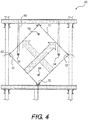
FIG. 4 is a schematic representation of a heat exchanger in accordance with an embodiment of the present invention positioned in a cooling tower or the like. -
FIG. 5 is a plan view of a heat exchange sheet depicting the features of the sheet in accordance with an embodiment of the present invention. - Referring now to the figures wherein like reference numerals indicate like elements, in
FIGS. 1 and2 a vapor condensing heat exchanger pack, generally designated 10, is illustrated in accordance with an embodiment of the present invention. As depicted, theheat exchanger pack 10 is constructed from a plurality of individual, thin heat exchange sheets, 12 and 14, respectively, that are connected or bonded to together to form thepack 10. Thesheets sheets sheets FIGS. 1 and2 , the pack has afirst flow path 16 through thepack 10, i.e. passageways betweensheets second flow path 18, oversheets 12 and undersheets 14. The aforementioned flow provides, and allows for two different airflow streams. In the embodiment depicted, the two air flow streams enter the heat exchanger pack at right angles to each other and are kept separate from one another by thesheets - As depicted in
FIG. 1 , to prevent the twoair streams seal 20 is formed in the thinsynthetic resin sheets edges 22 of thethin sheets sheets sheet 12 is depressed andsheet 14 is raised. The depressed and raised sheets, 12 and 14 respectively, meet in the center of theair passageways 16, or in other words, is depressed or raised one-half the width of thepassageways 16. Thisedge seal 20 is parallel to thepassageway 16 and therefore extends along the length of theair passageway 16 along the edges of entrance and exit ofair passageways 18. - Similarly, another
seal 21, opposite theseal 20 is formed by the raised edge of thethin sheet material 12 and the depressed edge of thethin sheet material 14, on the edge perpendicular to theseal 20, that meet in the center of theair passageway 18, or in other words, is depressed or raised one half the width of thepassageway 18. Whereasseal 20 is bonded, theedge seal 21 is a compression fit. Thisedge seal 21 extends the length of theair passageway 18 along the edges of the entrance and exit toair passageway 16. Although not shown, the other edge of matingthin sheet material 12 andthin sheet material 14 parallel to seal 20 is similarly bonded. Thus, theperpendicular passageways heat exchanger pack 10. - As illustrated in the figures, one edge extends positively off of the formed sheet and the other downward or negatively. In this arrangement a single sheet component can be used to form the basis of the entire heat exchanger pack. This is accomplished when assembling the pack by stacking the
sheets sheets - To properly align
sheets buttons Buttons mating sheets sheets buttons 28 that extend positively are conidial in shape having a flat top surface when viewed in the direction of the air flow throughpassageway 18. - The width of each of the passageways for either the cool air stream or the vapor laden air stream can be varied according to the design conditions of the particular task. Also, depending upon the orientation of the
pack 10, thecool air passageway 18 and the vaporladen air passageway 16 do not necessarily have to be of equal widths. - As illustrated in
FIGS. 1 and2 , thesheets parallel ribs 40 that extend along thesheet seals 21 and a second series of spaced apart,parallel ribs 42 that extend along thesheet top sheet 12, the first series ofribs 40 projects out of a plane in which the sheets lie, or out of the page of the drawing, as it extends along thesheet ribs 42 project into the plane, or into the page of the drawing, as it extends along thesheets 12. As illustrated inFIGS. 1 and2 each of theribs end regions 44. - As illustrated, the individual sheets of the heat exchanger packs 10 have a alternating configuration wherein
adjacent sheets sheet 12 as illustrated inFIGS. 1 and2 may simply be flipped over to become asheet 14, in which case, the first series ofribs 40, which project out of the page, now extend into the page while the second series ofribs 42, which project into the page, now extend out of the page. - As depicted in
FIGS. 1 and2 , theribs sheets respective ribs ribs 40 and the second serious ofribs 42 intersect one another at preferably a 90 degree angle to one another, however theribs ribs saddle 46. As illustrated inFIG. 2 , thesaddle 46 is a depression or dimple region that is disposed on the first series ofribs 40, wherein the saddle gradually projects a distance downward, into the plane in which the sheets lie, and then gradually upward out of the plane, to provide a round generally U-shaped depression or geometry on thesaddle 46. - As illustrated in
FIGS. 1 and2 , thesaddles 46 are located at nearly every point of intersection of theribs heat exchanger pack 10 for example, thesaddles 46 can function as load bearing regions for the adjacentindividual sheets heat exchanger pack 10 as a whole. The corner regions also assist and function with load bearing which will be discussed in further detail below. In the embodiments depicted, the saddles transfer various loads thesheets heat exchanger pack 10 may experience during operation, by providing a direct load path through theindividual sheets heat exchanger pack 10. The aforementioned orientation of the saddles and the resulting direct load path, along with the corner geometry of thesheets sheets heat exchanger pack 10. For example, in the illustrated embodiment, the saddles are arranged in an array which resists twisting of the pack, bending of the pack, and also resists collapsing of the individual air channels formed between the sheets of the pack. Thesaddle 46 shape provides an intersection with stiffness in the direction of both ribs. This permits effective load transfer between rib segments in either direction. - As previously described, the first series of
ribs 40 extends along thesheets ribs 42 extends along thesheets saddles 46. These intersections, provide a grid-like configuration on thesheets planar sections 48 that are located within the "borders" of the ribs. As illustrated inFIGS. 1 and2 , theplanar sections 48 have a generally square configuration and extend betweenribs 40 andribs 42. Theplanar sections 48 combine with theribs heat exchanger pack 10. The aforementioned flow channels also reduce the egress of air from one channel to an adjacent channel and vice versa, and provide single pathway for the air streams to flow through thepack 10 once the streams enter theheat exchanger pack 10. - The
planar sections 48 are generally planar and provide a flat surface in the channels through which the air travels. The flat surface is interrupted by theribs 40 and theribs 42 that extend away from the plane, as previously described. As illustrated inFIGS. 1 and2 , while some embodiments of the present invention includeplanar sections 48 having a generally smooth geometry, alternative embodiments may include thermalperformance enhancing ribs 50, for example. As depicted inFIGS. 1 and2 , theribs 50 protrude into the dry path, preferably, to stir the air flow traversing along said path. As illustrated theribs 50 are oriented or positioned at an angle to the air flow through the path. Preferably this angle ranges between approximately 20 degrees to approximately 90 degrees, and most preferably approximately 45 degrees. Also, the rib height may vary as a function of the dry path width. For example,rib 50 height may be 0.3 to 0.05 times the width of the dry path opening, and more preferably, 0.10 times the width height. Moreover, center to center spacing of theribs 50 on the paths may vary from 5 to 20 times the rib height. Preferably, the spacing is approximately 10 times therib 50 height. - As depicted in the figures, the
ribs 50 may extend from one or both faces of the dry path passages. Inembodiments utilizing ribs 50 on both faces, theribs 50 on opposing faces may be parallel or at an angle to each other. Furthermore, when saidribs 50 are oriented in a parallel configuration, a stagger is desirable from one face to the other so as not to block too much of the opening at any given cross section. The rib's geometry may be triangular, square, rectilinear, oblong, etc. In one preferred embodiment, the shape is square. Long continuous ribs as shown are preferable for water drainage. - In one embodiment of the present invention, preferred arrangement of the
performance ribs 50 is to be vertical when thepack 10 is installed in a diamond configuration as ahorizontal rib 50 orientation can cause them to fill with liquid and cause increased pressure drop. Accordingly, in theexemplary sheets 12 andsheets 14 depicted, each sheet differs from the other in that theribs 50 are opposite hand so that theribs 50 run or extend vertically in the diamond pack orientation. The aforementioned preferred vertical orientation of the performance ribs may, for example, be accomplished by utilizing separate unique vacuum molds to achieve the preferred vertical orientation. - Referring now to
FIGS. 1 and2 , eachsheet heat exchanger pack 10 has a four corner regions, each generally designated 52. Thecorner regions 52 each include a honeycomb, corrugated section orfoot 54. As illustrated inFIG. 2 , thecorrugated section 54 is preferably honeycomb in geometry and that provides a stiff foot or base to support the gravity load and prevent bending or flexing ofsheets pack 10. - Since moisture is condensed in the wet path, some condensate will run downward until it reaches the seal and then will run downward along the seal until it exits the tube. This seal must be water tight so as not to drip condensate into the dry air path ducting. While conventional glues and solvent welds may be used to provide the seals, in one embodiment said seals are preferably provided via radio frequency (RF) welding of mating tube halves. In one embodiment a RF welding machine may be used having metallic bars roughly the width of a peak and valley that will rest in the opposed peaks and valleys while RF energy is supplied therethrough. As energy is supplied to the bars, a thermal bond is formed at the touching regions. RF welding of a sheet pair in this method will typically be accomplished then by having an assembly of metal rods or bars that close on to the sheet pair from both sides of the sheet pair.
- Referring to
FIGS. 2 and3 , the dry path seal is clearly depicted, within thecorners 52 having alabyrinth geometry 56. Due to the labyrinth geometry, the compression seal of one tube to the next creates a robust dry air path seal. This seal requires no adhesive or weld. The labyrinth seal provides a more tortuous path for leaking air to traverse than a flat surface contact. The labyrinth geometry creates a rib that stiffens the flat edge. The aforementioned stiffened surface is more robust in maintaining its shape when the sheets are pressed against each other. - Referring now to
FIG. 4 , during operation, thecorner 52 allows the individual fill packs to easily engage the support structure orframe assembly 60 of the cooling tower within which the heat exchanger is employed. The support structure orframe assembly 60 of the typically include cross beams or supports having generally planar surfaces upon with the individual heat exchanger packs sit or rest. For example, theframe assembly 60 may include corner supports 62 for receiving thecorners 52 so that they are positioned in the tower in a preferred orientation. The aforementioned corrugated configuration of thecorner 52, in combination with the corner supports 62 provides a stiff, support surface that easily rests on, or engages, the planar surface of the cross beams or supports of the cooling tower. - An alternative to or an addition to reinforcing the bottom corner is to provide welded
sockets 64 in the in thesheets aforementioned sockets 64 have been added and may be utilized should high temperatures (121°F to 160°F) or less stiff material such as polypropylene necessitate their use. Wire hangers, generally designated 66, extend upward from the stainless steel support tubes and are suspended from framing above thepack 10. - Referring now to
FIG. 5 , a plan view of one of thesheets FIGS. 1-4 , is depicted. As previously discussed, the individual sheets have an alternating configuration wherein they mirror on another. - As previously discussed, the
sheet 100 comprises a first series of spaced apartribs 42 that extend along thesheet ribs 40 that extend along the seal 21 (not pictured) generally parallel to the horizontal axis B, and perpendicular to the vertical axis A. As described inFIGS. 1-4 , the first series ofribs 40 projects out of a plane in which thesheet 100 lies as it extends along thesheet 100, while the second series ofribs 42 project into the plane. - The
sheet 100, as previously discussed hasplanar sections 48 are generally planar and provide a flat surface in the channels through which the air travels. The flat surface is interrupted by theribs 40 and theribs 42 that extend away from the plane, as previously described. As illustrated, these sections may include thermalperformance enhancing ribs 50, for example. Theribs 50 protrude into the dry path, preferably, to stir the air flow traversing along said path. As illustrated theribs 50 are oriented or positioned at an angle to the air flow through the path. Preferably this angle ranges between approximately 20 degrees to approximately 90 degrees, and most preferably approximately 45 degrees. During operation, thesheet 100 is rotated approximately forty-five degrees as part to a fill pack, and thus theribs 50 extend generally parallel to the vertical axis A. - As previously discussed the
ribs 50 on both faces, theribs 50 on opposing faces may be parallel or at an angle to each other. Furthermore, when saidribs 50 are oriented in a parallel configuration, a stagger is desirable from one face to the other so as not to block too much of the opening at any given cross section. The rib's geometry may be triangular, square, rectilinear, oblong, etc. In one preferred embodiment, the shape is square. Long continuous ribs as shown are preferable for water drainage. - Also as previously discussed, the
sheet 100 has a four corner regions, each generally designated 52. Thecorner regions 52 each have a geometry such that when combined, the sheets provide a honeycomb, corrugated section or foot (not pictured) as described above. - The many features and advantages of the invention are apparent from the detailed specification, and thus, it is intended by the appended claims to cover all such features and advantages of the invention which fall within the true spirits and scope of the invention. Further, since numerous modifications and variations will readily occur to those skilled in the art, it is not desired to limit the invention to the exact construction and operation illustrated and described, and accordingly, all suitable modifications and equivalents may be resorted to, falling within the scope of the invention.
Claims (15)
- A fill pack (10) having plurality of sheets (12, 14, 100) each having first, second, third and fourth edges along, for use with a heat exchange apparatus having a first axis (B) and a second axis (A), wherein each sheet (12, 14) generally lies in a plane that is generally parallel to the first axis (B) and wherein the plurality of sheets (12, 14) combine to form a plurality of conduits, each sheet (12, 14) further comprising:a first vertical rib (40) that extends in a first direction generally parallel to the first axis (B) along the sheet (12, 14), substantially all the way between the first and second edges, wherein said first vertical rib (40) protrudes in a second direction out of the plane;a second vertical rib (40) that extends in the first direction along the sheet (12, 14, 100), substantially all the way between the first and second edges generally parallel to said first vertical rib (40), wherein said second vertical rib (40) protrudes in the second direction out of the plane;a first horizontal rib (42) that extends in a third direction generally parallel to the second axis (A) along the sheet (12, 14, 100) substantially all the way between the third and fourth edges, wherein said first horizontal rib (42) protrudes in a fourth direction opposite said second direction, into the plane, wherein said first horizontal rib (42) intersects said first vertical rib (40);a second horizontal rib (42) that extends in the third direction along the sheet (12, 14, 100) substantially all the way between the third and fourth edges generally parallel to said first horizontal rib (42), wherein said second horizontal rib (42) protrudes in the fourth direction opposite said second direction, into the plane, wherein said second horizontal rib (42) intersects said second vertical rib (40), wherein said first and second vertical ribs (40) and said first and second horizontal ribs (42) form a boundary that surrounds at least one generally planar region (48),characterised in that said at least one generally planar region (48) further comprises performance ribs (50) disposed thereon at an angle to the first axis (B), at least one performance rib (50) being continuous from one horizontal rib (42) to one vertical rib (40).
- The fill pack (10) according to claim 1, wherein said angle is equal to approximately 20 degrees to approximately 90 degrees to the first axis (B).
- The fill pack (10) according to claim 2, wherein said angle is equal to approximately 45 degrees to the first axis (B).
- The fill pack (10) according to claim 1, each sheet (12, 14, 100) further comprising:
at least one hardened corner (52), wherein said first hardened corner includes said plurality of conduits wherein adjacent ones of said plurality of conduits contact one another. - The fill pack (10) according to claim 1, further comprising a saddle region (46) located at each of the intersections between said first vertical and horizontal ribs (40, 42) and said second vertical and horizontal ribs (40, 42).
- The fill pack (10) according to claim 4, wherein said adjacent conduits that contact one another combine to form a honeycomb geometry.
- The fill pack (10) according to claim 1, wherein said first horizontal rib (42) and said second horizontal rib (42) each comprise:a first wall having a top region, a middle region and a lower region;a second wall having a top region, a middle region and a lower region; anda base that extends between said first wall and said second wall.
- The fill pack (10) according to claim 1, wherein said sheet (12, 14, 100) is made of polyvinyl chloride (PVC).
- The fill pack (10) according to claim 6, wherein each hardened corner (52) of each sheet (12, 14, 100) is positioned so that the honeycomb geometries of adjacent sheets contact each other.
- The fill pack (10) according to claim 4, wherein said at least one hardened corner (52) is a plurality of hardened corners (52).
- A method for condensing water utilizing a heat exchange fill pack (10) as defined in claim 1 for use with a heat exchange apparatus having a first axis (B) and a second axis (A), comprising:passing an air stream (16) to be cooled through a plurality of first conduits, while concurrently passing a cooling air stream through a plurality of second conduits, the first and second conduits formed from a plurality of heat exchange sheets (12, 14, 100), each sheet (12, 14, 100) having first, second, third and fourth edges along with first, second, third and fourth corners, wherein each sheet (12, 14, 100) generally lies in a plane that is generally parallel to the first axis (B), each sheet (12, 14, 100) further comprising:a first vertical rib (40) that extends in a first direction generally parallel to the first axis (B) along the sheet (12, 14, 100), substantially all the way between the first and second edges, wherein said first vertical rib (40) protrudes in a second direction out of the plane;a second vertical rib (40) that extends in the first direction along the sheet (12, 14, 100), substantially all the way between the first and second edges generally parallel to said first vertical rib (40), wherein said second vertical rib (40) protrudes in the second direction out of the plane;a first horizontal rib (42) that extends in a third direction generally parallel to the second axis (A) along the sheet (12, 14, 100) substantially all the way between the third and fourth edges, wherein said first horizontal rib (42) protrudes in a fourth direction opposite said second direction, into the plane, wherein said first horizontal rib (42) intersects said first vertical rib (40);a second horizontal rib (42) that extends in the third direction along the sheet (12, 14, 100) substantially all the way between the third and fourth edges generally parallel to said first horizontal rib (42), wherein said second horizontal rib (42) protrudes in the fourth direction opposite said second direction, into the plane, wherein said second horizontal rib (42) intersects said second vertical rib (40), wherein said first and second vertical ribs (40) and said first and second horizontal ribs (42) form a boundary that surrounds at least one generally planar region (48);flowing an air stream (18) over the sheet (12, 14, 100) such that the performance ribs (50) provide heat exchange; and condensing water from the air stream (18) to be cooled.
- The method according to claim 11, further comprising at least one hardened corner (52), wherein said at least one hardened corner (52) includes said plurality of first and second conduits wherein adjacent ones of said plurality of conduits contact one another.
- The method accordingly to claim 11, wherein the performance ribs (50) extend generally at an angle to the first axis (B).
- The method according to claim 12, wherein said adjacent conduits that contact one another combine to form a honeycomb geometry.
- The method according to claim 12, wherein said angle is equal to approximately 20 degrees to approximately 90 degrees to the first axis (B).
Applications Claiming Priority (2)
| Application Number | Priority Date | Filing Date | Title |
|---|---|---|---|
| US13/290,887 US8827249B2 (en) | 2011-11-07 | 2011-11-07 | Air-to-air atmospheric exchanger |
| PCT/US2012/063487 WO2013070530A1 (en) | 2011-11-07 | 2012-11-05 | Air-to-air atmospheric exchanger |
Publications (3)
| Publication Number | Publication Date |
|---|---|
| EP2776775A1 EP2776775A1 (en) | 2014-09-17 |
| EP2776775A4 EP2776775A4 (en) | 2015-06-24 |
| EP2776775B1 true EP2776775B1 (en) | 2018-06-20 |
Family
ID=48223156
Family Applications (1)
| Application Number | Title | Priority Date | Filing Date |
|---|---|---|---|
| EP12847681.9A Active EP2776775B1 (en) | 2011-11-07 | 2012-11-05 | Air-to-air atmospheric exchanger |
Country Status (8)
| Country | Link |
|---|---|
| US (1) | US8827249B2 (en) |
| EP (1) | EP2776775B1 (en) |
| JP (1) | JP6338529B2 (en) |
| KR (1) | KR102011533B1 (en) |
| CN (1) | CN103975218B (en) |
| AU (1) | AU2012336130B2 (en) |
| CA (1) | CA2854181C (en) |
| WO (1) | WO2013070530A1 (en) |
Cited By (1)
| Publication number | Priority date | Publication date | Assignee | Title |
|---|---|---|---|---|
| RU2757084C1 (en) * | 2018-11-26 | 2021-10-11 | Альфа Лаваль Корпорейт Аб | Heat transfer plate |
Families Citing this family (15)
| Publication number | Priority date | Publication date | Assignee | Title |
|---|---|---|---|---|
| US8833741B2 (en) * | 2011-11-07 | 2014-09-16 | Spx Cooling Technologies, Inc. | Air-to-air atmospheric exchanger |
| US10222146B2 (en) * | 2013-09-12 | 2019-03-05 | Spx Cooling Technologies, Inc. | Air-to-air heat exchanger bypass for wet cooling tower apparatus and method |
| CN104121792B (en) * | 2014-07-31 | 2016-08-24 | 叶立英 | Indirect evaporating-cooling core body |
| EP3237826B1 (en) * | 2014-12-23 | 2022-11-30 | Evapco, Inc. | Bi-directional fill for use in cooling towers |
| EP3447429B1 (en) * | 2017-08-22 | 2023-06-07 | InnoHeat Sweden AB | Heat exchanger plate and heat exchanger |
| EP3447427B1 (en) * | 2017-08-22 | 2020-03-18 | InnoHeat Sweden AB | Heat exchanger |
| US11136763B2 (en) * | 2018-05-01 | 2021-10-05 | Hanover Prest-Paving Company | Aerodynamically stable roof paver system and ballast block therefor |
| WO2020191198A1 (en) | 2019-03-19 | 2020-09-24 | Baltimore Aircoil Company, Inc. | Heat exchanger having plume abatement assembly bypass |
| CN111928705B (en) * | 2019-05-13 | 2022-03-25 | 亚浩电子五金塑胶(惠州)有限公司 | Heat radiator with gravity type loop heat pipe |
| EP4073438A4 (en) | 2019-12-11 | 2023-12-20 | Baltimore Aircoil Company, Inc. | HEAT EXCHANGER SYSTEM WITH OPTIMIZATION BASED ON MACHINE LEARNING |
| US11433370B2 (en) * | 2019-12-20 | 2022-09-06 | Brentwood Industries, Inc. | Fill sheets and related fill pack assemblies |
| US11976882B2 (en) | 2020-11-23 | 2024-05-07 | Baltimore Aircoil Company, Inc. | Heat rejection apparatus, plume abatement system, and method |
| CN218296816U (en) * | 2022-06-14 | 2023-01-13 | 中化工程沧州冷却技术有限公司 | Heat exchange module |
| KR20250029920A (en) | 2022-06-24 | 2025-03-05 | 벌티모어 에어코일 컴파니 인코포레이티드 | Heat transfer device and method |
| US12260925B2 (en) * | 2023-03-14 | 2025-03-25 | SanDisk Technologies, Inc. | Data integrity check in non-volatile storage |
Family Cites Families (22)
| Publication number | Priority date | Publication date | Assignee | Title |
|---|---|---|---|---|
| US3733063A (en) * | 1971-09-24 | 1973-05-15 | Marley Co | Chevron ribbed fill unit for water cooling tower |
| GB1433379A (en) * | 1973-08-24 | 1976-04-28 | Nevsky Mashinostroitelny Z Im | Heat exchange apparatus |
| JPS5332878A (en) * | 1976-09-08 | 1978-03-28 | Hisaka Works Ltd | Condenser |
| DE2953392C2 (en) * | 1979-08-23 | 1984-12-13 | Hisaka Works Ltd., Osaka | Plate-shaped heat exchanger |
| US4361426A (en) | 1981-01-22 | 1982-11-30 | Baltimore Aircoil Company, Inc. | Angularly grooved corrugated fill for water cooling tower |
| US4514144A (en) | 1983-06-20 | 1985-04-30 | General Electric Company | Angled turbulence promoter |
| JPS63194192A (en) * | 1987-02-04 | 1988-08-11 | Matsushita Seiko Co Ltd | Total heat exchanger |
| US4801410A (en) | 1987-07-02 | 1989-01-31 | The Marley Cooling Tower Company | Plastic fill sheet for water cooling tower with air guiding spacers |
| JPH02279992A (en) * | 1989-04-21 | 1990-11-15 | Tadao Totsuka | Heat exchanger element |
| EP0982427B1 (en) | 1998-08-25 | 2003-03-05 | Joma-Polytec Kunststofftechnik GmbH | Cross flow heat exchanger for laundry drier with condenser |
| US6260830B1 (en) | 1998-11-25 | 2001-07-17 | Baltimore Aircoil Company, Inc. | Film fill-pack for inducement of spiraling gas flow in heat and mass transfer contact apparatus with self-spacing fill-sheets |
| US6517058B1 (en) * | 2000-03-02 | 2003-02-11 | Sandkuhl Clay Works, Inc. | Fill packs for use in heat and mass transfer devices |
| US7328886B2 (en) | 2001-10-11 | 2008-02-12 | Spx Cooling Technologies, Inc. | Air-to-air atmospheric heat exchanger for condensing cooling tower effluent |
| US6663087B2 (en) * | 2001-10-11 | 2003-12-16 | Marley Cooling Technologies, Inc. | Air-to-air atmospheric exchanger for condensing cooling tower effluent |
| CN2530236Y (en) * | 2001-11-23 | 2003-01-08 | 财团法人工业技术研究院 | A new type of fin with rib-type vortex generators |
| GB0210434D0 (en) * | 2002-05-08 | 2002-06-12 | Smiths Group Plc | Apparatus |
| EP1682842B1 (en) * | 2003-10-28 | 2014-06-04 | Behr GmbH & Co. KG | Flow channel for a heat exchanger, and heat exchanger comprising such flow channels |
| JP2008116138A (en) * | 2006-11-06 | 2008-05-22 | Xenesys Inc | Heat exchange plate |
| SE534306C2 (en) * | 2008-06-17 | 2011-07-05 | Alfa Laval Corp Ab | Heat exchanger plate and plate heat exchanger |
| JP2010025487A (en) * | 2008-07-23 | 2010-02-04 | Nippon Spindle Mfg Co Ltd | Sealed cooling tower |
| WO2010069874A1 (en) * | 2008-12-17 | 2010-06-24 | Swep International Ab | Reinforced heat exchanger |
| US8771457B2 (en) * | 2008-12-19 | 2014-07-08 | Spx Cooling Technologies, Inc. | Fill pack assembly and method with bonded sheet pairs |
-
2011
- 2011-11-07 US US13/290,887 patent/US8827249B2/en active Active
-
2012
- 2012-11-05 JP JP2014541129A patent/JP6338529B2/en active Active
- 2012-11-05 AU AU2012336130A patent/AU2012336130B2/en active Active
- 2012-11-05 CA CA2854181A patent/CA2854181C/en active Active
- 2012-11-05 CN CN201280059745.4A patent/CN103975218B/en active Active
- 2012-11-05 KR KR1020147015079A patent/KR102011533B1/en active Active
- 2012-11-05 EP EP12847681.9A patent/EP2776775B1/en active Active
- 2012-11-05 WO PCT/US2012/063487 patent/WO2013070530A1/en not_active Ceased
Non-Patent Citations (1)
| Title |
|---|
| None * |
Cited By (2)
| Publication number | Priority date | Publication date | Assignee | Title |
|---|---|---|---|---|
| RU2757084C1 (en) * | 2018-11-26 | 2021-10-11 | Альфа Лаваль Корпорейт Аб | Heat transfer plate |
| US11499786B2 (en) | 2018-11-26 | 2022-11-15 | Alfa Laval Corporate Ab | Heat transfer plate |
Also Published As
| Publication number | Publication date |
|---|---|
| US20130113127A1 (en) | 2013-05-09 |
| EP2776775A4 (en) | 2015-06-24 |
| WO2013070530A1 (en) | 2013-05-16 |
| CN103975218B (en) | 2020-04-03 |
| CA2854181A1 (en) | 2013-05-16 |
| AU2012336130B2 (en) | 2017-08-24 |
| AU2012336130A1 (en) | 2014-05-22 |
| KR20140088608A (en) | 2014-07-10 |
| JP2014532852A (en) | 2014-12-08 |
| JP6338529B2 (en) | 2018-06-06 |
| US8827249B2 (en) | 2014-09-09 |
| EP2776775A1 (en) | 2014-09-17 |
| CN103975218A (en) | 2014-08-06 |
| KR102011533B1 (en) | 2019-08-16 |
| CA2854181C (en) | 2018-12-04 |
Similar Documents
| Publication | Publication Date | Title |
|---|---|---|
| EP2776776B1 (en) | Air-to-air atmospheric heat exchanger | |
| CA2854181C (en) | Air-to-air atmospheric heat exchanger | |
| US7328886B2 (en) | Air-to-air atmospheric heat exchanger for condensing cooling tower effluent | |
| US6663694B2 (en) | Air-to-air atmospheric exchanger for condensing cooling tower effluent | |
| US6663087B2 (en) | Air-to-air atmospheric exchanger for condensing cooling tower effluent | |
| US7128310B2 (en) | Air-to-air atmospheric heat exchanger for condensing cooling tower effluent | |
| US6314752B1 (en) | Mass and heat transfer devices and methods of use | |
| EP0052009A2 (en) | Apparatus for ensuring heat exchange between a gas flow and a heat exchanger | |
| CN118056109A (en) | Direct heat exchange packing | |
| AU2002342032A1 (en) | Air-to-air atmospheric heat exchanger for condensing cooling tower effluent | |
| AU2002342033A1 (en) | Air-to-air atmospheric heat exchanger for condensing cooling tower effluent |
Legal Events
| Date | Code | Title | Description |
|---|---|---|---|
| PUAI | Public reference made under article 153(3) epc to a published international application that has entered the european phase |
Free format text: ORIGINAL CODE: 0009012 |
|
| 17P | Request for examination filed |
Effective date: 20140516 |
|
| AK | Designated contracting states |
Kind code of ref document: A1 Designated state(s): AL AT BE BG CH CY CZ DE DK EE ES FI FR GB GR HR HU IE IS IT LI LT LU LV MC MK MT NL NO PL PT RO RS SE SI SK SM TR |
|
| DAX | Request for extension of the european patent (deleted) | ||
| RA4 | Supplementary search report drawn up and despatched (corrected) |
Effective date: 20150526 |
|
| RIC1 | Information provided on ipc code assigned before grant |
Ipc: F28F 3/08 20060101AFI20150519BHEP |
|
| GRAP | Despatch of communication of intention to grant a patent |
Free format text: ORIGINAL CODE: EPIDOSNIGR1 |
|
| INTG | Intention to grant announced |
Effective date: 20180305 |
|
| GRAS | Grant fee paid |
Free format text: ORIGINAL CODE: EPIDOSNIGR3 |
|
| GRAA | (expected) grant |
Free format text: ORIGINAL CODE: 0009210 |
|
| AK | Designated contracting states |
Kind code of ref document: B1 Designated state(s): AL AT BE BG CH CY CZ DE DK EE ES FI FR GB GR HR HU IE IS IT LI LT LU LV MC MK MT NL NO PL PT RO RS SE SI SK SM TR |
|
| REG | Reference to a national code |
Ref country code: GB Ref legal event code: FG4D |
|
| REG | Reference to a national code |
Ref country code: IE Ref legal event code: FG4D |
|
| REG | Reference to a national code |
Ref country code: DE Ref legal event code: R096 Ref document number: 602012047725 Country of ref document: DE |
|
| REG | Reference to a national code |
Ref country code: AT Ref legal event code: REF Ref document number: 1010902 Country of ref document: AT Kind code of ref document: T Effective date: 20180715 |
|
| REG | Reference to a national code |
Ref country code: NL Ref legal event code: MP Effective date: 20180620 |
|
| PG25 | Lapsed in a contracting state [announced via postgrant information from national office to epo] |
Ref country code: FI Free format text: LAPSE BECAUSE OF FAILURE TO SUBMIT A TRANSLATION OF THE DESCRIPTION OR TO PAY THE FEE WITHIN THE PRESCRIBED TIME-LIMIT Effective date: 20180620 Ref country code: NO Free format text: LAPSE BECAUSE OF FAILURE TO SUBMIT A TRANSLATION OF THE DESCRIPTION OR TO PAY THE FEE WITHIN THE PRESCRIBED TIME-LIMIT Effective date: 20180920 Ref country code: SE Free format text: LAPSE BECAUSE OF FAILURE TO SUBMIT A TRANSLATION OF THE DESCRIPTION OR TO PAY THE FEE WITHIN THE PRESCRIBED TIME-LIMIT Effective date: 20180620 Ref country code: LT Free format text: LAPSE BECAUSE OF FAILURE TO SUBMIT A TRANSLATION OF THE DESCRIPTION OR TO PAY THE FEE WITHIN THE PRESCRIBED TIME-LIMIT Effective date: 20180620 Ref country code: BG Free format text: LAPSE BECAUSE OF FAILURE TO SUBMIT A TRANSLATION OF THE DESCRIPTION OR TO PAY THE FEE WITHIN THE PRESCRIBED TIME-LIMIT Effective date: 20180920 |
|
| REG | Reference to a national code |
Ref country code: LT Ref legal event code: MG4D |
|
| PG25 | Lapsed in a contracting state [announced via postgrant information from national office to epo] |
Ref country code: RS Free format text: LAPSE BECAUSE OF FAILURE TO SUBMIT A TRANSLATION OF THE DESCRIPTION OR TO PAY THE FEE WITHIN THE PRESCRIBED TIME-LIMIT Effective date: 20180620 Ref country code: HR Free format text: LAPSE BECAUSE OF FAILURE TO SUBMIT A TRANSLATION OF THE DESCRIPTION OR TO PAY THE FEE WITHIN THE PRESCRIBED TIME-LIMIT Effective date: 20180620 Ref country code: LV Free format text: LAPSE BECAUSE OF FAILURE TO SUBMIT A TRANSLATION OF THE DESCRIPTION OR TO PAY THE FEE WITHIN THE PRESCRIBED TIME-LIMIT Effective date: 20180620 Ref country code: GR Free format text: LAPSE BECAUSE OF FAILURE TO SUBMIT A TRANSLATION OF THE DESCRIPTION OR TO PAY THE FEE WITHIN THE PRESCRIBED TIME-LIMIT Effective date: 20180921 |
|
| REG | Reference to a national code |
Ref country code: AT Ref legal event code: MK05 Ref document number: 1010902 Country of ref document: AT Kind code of ref document: T Effective date: 20180620 |
|
| PG25 | Lapsed in a contracting state [announced via postgrant information from national office to epo] |
Ref country code: NL Free format text: LAPSE BECAUSE OF FAILURE TO SUBMIT A TRANSLATION OF THE DESCRIPTION OR TO PAY THE FEE WITHIN THE PRESCRIBED TIME-LIMIT Effective date: 20180620 |
|
| PG25 | Lapsed in a contracting state [announced via postgrant information from national office to epo] |
Ref country code: RO Free format text: LAPSE BECAUSE OF FAILURE TO SUBMIT A TRANSLATION OF THE DESCRIPTION OR TO PAY THE FEE WITHIN THE PRESCRIBED TIME-LIMIT Effective date: 20180620 Ref country code: SK Free format text: LAPSE BECAUSE OF FAILURE TO SUBMIT A TRANSLATION OF THE DESCRIPTION OR TO PAY THE FEE WITHIN THE PRESCRIBED TIME-LIMIT Effective date: 20180620 Ref country code: AT Free format text: LAPSE BECAUSE OF FAILURE TO SUBMIT A TRANSLATION OF THE DESCRIPTION OR TO PAY THE FEE WITHIN THE PRESCRIBED TIME-LIMIT Effective date: 20180620 Ref country code: EE Free format text: LAPSE BECAUSE OF FAILURE TO SUBMIT A TRANSLATION OF THE DESCRIPTION OR TO PAY THE FEE WITHIN THE PRESCRIBED TIME-LIMIT Effective date: 20180620 Ref country code: IS Free format text: LAPSE BECAUSE OF FAILURE TO SUBMIT A TRANSLATION OF THE DESCRIPTION OR TO PAY THE FEE WITHIN THE PRESCRIBED TIME-LIMIT Effective date: 20181020 Ref country code: PL Free format text: LAPSE BECAUSE OF FAILURE TO SUBMIT A TRANSLATION OF THE DESCRIPTION OR TO PAY THE FEE WITHIN THE PRESCRIBED TIME-LIMIT Effective date: 20180620 Ref country code: CZ Free format text: LAPSE BECAUSE OF FAILURE TO SUBMIT A TRANSLATION OF THE DESCRIPTION OR TO PAY THE FEE WITHIN THE PRESCRIBED TIME-LIMIT Effective date: 20180620 |
|
| PG25 | Lapsed in a contracting state [announced via postgrant information from national office to epo] |
Ref country code: SM Free format text: LAPSE BECAUSE OF FAILURE TO SUBMIT A TRANSLATION OF THE DESCRIPTION OR TO PAY THE FEE WITHIN THE PRESCRIBED TIME-LIMIT Effective date: 20180620 Ref country code: ES Free format text: LAPSE BECAUSE OF FAILURE TO SUBMIT A TRANSLATION OF THE DESCRIPTION OR TO PAY THE FEE WITHIN THE PRESCRIBED TIME-LIMIT Effective date: 20180620 |
|
| REG | Reference to a national code |
Ref country code: DE Ref legal event code: R097 Ref document number: 602012047725 Country of ref document: DE |
|
| PLBE | No opposition filed within time limit |
Free format text: ORIGINAL CODE: 0009261 |
|
| STAA | Information on the status of an ep patent application or granted ep patent |
Free format text: STATUS: NO OPPOSITION FILED WITHIN TIME LIMIT |
|
| 26N | No opposition filed |
Effective date: 20190321 |
|
| PG25 | Lapsed in a contracting state [announced via postgrant information from national office to epo] |
Ref country code: DK Free format text: LAPSE BECAUSE OF FAILURE TO SUBMIT A TRANSLATION OF THE DESCRIPTION OR TO PAY THE FEE WITHIN THE PRESCRIBED TIME-LIMIT Effective date: 20180620 |
|
| REG | Reference to a national code |
Ref country code: CH Ref legal event code: PL |
|
| PG25 | Lapsed in a contracting state [announced via postgrant information from national office to epo] |
Ref country code: MC Free format text: LAPSE BECAUSE OF FAILURE TO SUBMIT A TRANSLATION OF THE DESCRIPTION OR TO PAY THE FEE WITHIN THE PRESCRIBED TIME-LIMIT Effective date: 20180620 Ref country code: LU Free format text: LAPSE BECAUSE OF NON-PAYMENT OF DUE FEES Effective date: 20181105 |
|
| REG | Reference to a national code |
Ref country code: BE Ref legal event code: MM Effective date: 20181130 |
|
| REG | Reference to a national code |
Ref country code: IE Ref legal event code: MM4A |
|
| PG25 | Lapsed in a contracting state [announced via postgrant information from national office to epo] |
Ref country code: CH Free format text: LAPSE BECAUSE OF NON-PAYMENT OF DUE FEES Effective date: 20181130 Ref country code: LI Free format text: LAPSE BECAUSE OF NON-PAYMENT OF DUE FEES Effective date: 20181130 Ref country code: SI Free format text: LAPSE BECAUSE OF FAILURE TO SUBMIT A TRANSLATION OF THE DESCRIPTION OR TO PAY THE FEE WITHIN THE PRESCRIBED TIME-LIMIT Effective date: 20180620 |
|
| PG25 | Lapsed in a contracting state [announced via postgrant information from national office to epo] |
Ref country code: IE Free format text: LAPSE BECAUSE OF NON-PAYMENT OF DUE FEES Effective date: 20181105 Ref country code: FR Free format text: LAPSE BECAUSE OF NON-PAYMENT OF DUE FEES Effective date: 20181130 |
|
| PG25 | Lapsed in a contracting state [announced via postgrant information from national office to epo] |
Ref country code: AL Free format text: LAPSE BECAUSE OF FAILURE TO SUBMIT A TRANSLATION OF THE DESCRIPTION OR TO PAY THE FEE WITHIN THE PRESCRIBED TIME-LIMIT Effective date: 20180620 Ref country code: BE Free format text: LAPSE BECAUSE OF NON-PAYMENT OF DUE FEES Effective date: 20181130 |
|
| PG25 | Lapsed in a contracting state [announced via postgrant information from national office to epo] |
Ref country code: MT Free format text: LAPSE BECAUSE OF NON-PAYMENT OF DUE FEES Effective date: 20181105 |
|
| PG25 | Lapsed in a contracting state [announced via postgrant information from national office to epo] |
Ref country code: TR Free format text: LAPSE BECAUSE OF FAILURE TO SUBMIT A TRANSLATION OF THE DESCRIPTION OR TO PAY THE FEE WITHIN THE PRESCRIBED TIME-LIMIT Effective date: 20180620 |
|
| PG25 | Lapsed in a contracting state [announced via postgrant information from national office to epo] |
Ref country code: PT Free format text: LAPSE BECAUSE OF FAILURE TO SUBMIT A TRANSLATION OF THE DESCRIPTION OR TO PAY THE FEE WITHIN THE PRESCRIBED TIME-LIMIT Effective date: 20180620 |
|
| PG25 | Lapsed in a contracting state [announced via postgrant information from national office to epo] |
Ref country code: MK Free format text: LAPSE BECAUSE OF NON-PAYMENT OF DUE FEES Effective date: 20180620 Ref country code: HU Free format text: LAPSE BECAUSE OF FAILURE TO SUBMIT A TRANSLATION OF THE DESCRIPTION OR TO PAY THE FEE WITHIN THE PRESCRIBED TIME-LIMIT; INVALID AB INITIO Effective date: 20121105 Ref country code: CY Free format text: LAPSE BECAUSE OF FAILURE TO SUBMIT A TRANSLATION OF THE DESCRIPTION OR TO PAY THE FEE WITHIN THE PRESCRIBED TIME-LIMIT Effective date: 20180620 |
|
| PGFP | Annual fee paid to national office [announced via postgrant information from national office to epo] |
Ref country code: DE Payment date: 20251128 Year of fee payment: 14 |
|
| PGFP | Annual fee paid to national office [announced via postgrant information from national office to epo] |
Ref country code: GB Payment date: 20251127 Year of fee payment: 14 |
|
| PGFP | Annual fee paid to national office [announced via postgrant information from national office to epo] |
Ref country code: IT Payment date: 20251119 Year of fee payment: 14 |