EP2776356B1 - Elevator car - Google Patents
Elevator car Download PDFInfo
- Publication number
- EP2776356B1 EP2776356B1 EP11794418.1A EP11794418A EP2776356B1 EP 2776356 B1 EP2776356 B1 EP 2776356B1 EP 11794418 A EP11794418 A EP 11794418A EP 2776356 B1 EP2776356 B1 EP 2776356B1
- Authority
- EP
- European Patent Office
- Prior art keywords
- wall elements
- flatbar
- perforations
- bolts
- elevator car
- Prior art date
- Legal status (The legal status is an assumption and is not a legal conclusion. Google has not performed a legal analysis and makes no representation as to the accuracy of the status listed.)
- Active
Links
Images


Classifications
-
- B—PERFORMING OPERATIONS; TRANSPORTING
- B66—HOISTING; LIFTING; HAULING
- B66B—ELEVATORS; ESCALATORS OR MOVING WALKWAYS
- B66B11/00—Main component parts of lifts in, or associated with, buildings or other structures
- B66B11/02—Cages, i.e. cars
- B66B11/0226—Constructional features, e.g. walls assembly, decorative panels, comfort equipment, thermal or sound insulation
- B66B11/0253—Fixation of wall panels
-
- B—PERFORMING OPERATIONS; TRANSPORTING
- B66—HOISTING; LIFTING; HAULING
- B66B—ELEVATORS; ESCALATORS OR MOVING WALKWAYS
- B66B11/00—Main component parts of lifts in, or associated with, buildings or other structures
- B66B11/02—Cages, i.e. cars
- B66B11/0226—Constructional features, e.g. walls assembly, decorative panels, comfort equipment, thermal or sound insulation
-
- E—FIXED CONSTRUCTIONS
- E04—BUILDING
- E04B—GENERAL BUILDING CONSTRUCTIONS; WALLS, e.g. PARTITIONS; ROOFS; FLOORS; CEILINGS; INSULATION OR OTHER PROTECTION OF BUILDINGS
- E04B1/00—Constructions in general; Structures which are not restricted either to walls, e.g. partitions, or floors or ceilings or roofs
- E04B1/38—Connections for building structures in general
- E04B1/61—Connections for building structures in general of slab-shaped building elements with each other
- E04B1/6108—Connections for building structures in general of slab-shaped building elements with each other the frontal surfaces of the slabs connected together
- E04B1/612—Connections for building structures in general of slab-shaped building elements with each other the frontal surfaces of the slabs connected together by means between frontal surfaces
- E04B1/6125—Connections for building structures in general of slab-shaped building elements with each other the frontal surfaces of the slabs connected together by means between frontal surfaces with protrusions on the one frontal surface co-operating with recesses in the other frontal surface
- E04B1/6141—Connections for building structures in general of slab-shaped building elements with each other the frontal surfaces of the slabs connected together by means between frontal surfaces with protrusions on the one frontal surface co-operating with recesses in the other frontal surface the connection made by an additional locking key
-
- Y—GENERAL TAGGING OF NEW TECHNOLOGICAL DEVELOPMENTS; GENERAL TAGGING OF CROSS-SECTIONAL TECHNOLOGIES SPANNING OVER SEVERAL SECTIONS OF THE IPC; TECHNICAL SUBJECTS COVERED BY FORMER USPC CROSS-REFERENCE ART COLLECTIONS [XRACs] AND DIGESTS
- Y10—TECHNICAL SUBJECTS COVERED BY FORMER USPC
- Y10T—TECHNICAL SUBJECTS COVERED BY FORMER US CLASSIFICATION
- Y10T29/00—Metal working
- Y10T29/49—Method of mechanical manufacture
- Y10T29/49826—Assembling or joining
- Y10T29/49947—Assembling or joining by applying separate fastener
- Y10T29/49963—Threaded fastener
Definitions
- the present invention refers to an elevator car comprising a support frame, a floor structure and a ceiling structure, as well as at least one car door and side walls extending between the floor structure and the ceiling structure.
- the side walls consist of several wall elements which are aligned end-to-end within one wall.
- the wall elements to be connected are arranged perpendicular to each other the wall elements are arranged end to side.
- the present invention relates to this basic layout of an elevator car whereby it is particularly directed to high rise elevators or fast driving elevators where the noise of the fast running elevator car increases essentially compared to usual elevators with car velocities about 1 m/s. Elevator cars of such high rise elevators have velocities of two to ten m/s. Accordingly, there is a desire for elevator cars with a good noise insulation.
- the EP 0 585 945 A1 as well as the US 2006/0289242 A1 show elevator cars having multi-layer wall elements for better noise insulation.
- the US 4,199,907 discloses a connecting method for non-metal massive panels of elevator cars with flatbars having one vertical and one tilted longhole for the connection of the wall elements.
- the object of the invention is solved with an elevator car according to claim 1.
- a method for building an elevator car with good noise insulating properties is subject matter of claim 12.
- Preferred embodiments of the invention are subject matter of the corresponding sub claims.
- wall elements are used with good noise insulating properties comprising at least one support material, e.g. panels of metal sheet, plastic panels or fiberboard plates (MDF) and at least one noise insulating material as e.g. stone wool or glass wool.
- MDF plastic panels or fiberboard plates
- noise insulating material e.g. stone wool or glass wool.
- MDF fiberboard plates
- wall elements also combinations of several support materials and noise insulating materials may be chosen as desired.
- the use of wall elements with good insulting properties essentially reduces the noise level in the elevator car even during fast travel of the elevator car in a high rise elevator.
- a particular joint is provided in the connection area of two adjacent wall elements. Accordingly, one flatbar is used which covers a part of both adjacent wall elements to be connected on both sides of the joint as well as the connecting area itself.
- This flatbar is connected with fixing elements to at least one of both adjacent wall elements, preferably to both adjacent wall elements.
- a kind of labyrinth seal is provided in the joint area between both adjacent wall elements which labyrinth seal has good noise insulting properties.
- the joint between the two wall elements is not leaking so that it does not allow noise to pass through.
- single wall elements may be changed or replaced one by one, if needed.
- the connecting of wall elements by means of the flatbars is fast and no special tools are needed.
- the flatbar is connected via fixing elements to both adjacent wall elements which results in a better rigidity of the joint and better noise insulating properties.
- fixing elements bolts, particularly punch nuts may be used to fix the flatbar to the wall elements.
- the perforations comprise first and second perforations and the first perforations extend over the first of two adjacent wall elements and the second perforations extend over the second of said wall elements.
- the perforations comprise or consist of tilted portions, whereby the tilted portions of the first and second perforations are tilted towards each other. With such a configuration of the perforations it is possible to use the tilted portion for pressing the adjacent wall elements together by moving the flatbar vertically.
- the flatbar maybe any longitudinal band, strip, sheet or bar, e.g. a metal or plastics sheet strip.
- the flatbar could be embodied as a one-piece element which extends from the floor to the ceiling of the car, e.g. over the total height of the side walls, or it may comprise several parts are mounted above each other in vertical direction.
- the flatbar is an element which only extends in one plane and preferably having a thickness between 1 and 5 mm.
- Such a flatbar is easy to handle and allows a fast and economic joint between adjacent wall elements as it only has to be brought to the surfaces thereof and does not interfere with the inner structure or end structure of the wall elements.
- the flatbar is mounted on the surface of the wall elements facing the car inside because in this case the side walls can be easily installed from the elevator car. But it is also possible to mount the flatbars on the side of the wall elements facing the shaft. If a very rigid construction is to be achieved the flatbars may be mounted on both sides of the wall elements.
- the flatbar On the side facing the wall elements the flatbar may comprise a sealing or damping material as e.g. rubber or soft plastics to improve the noise insulation in the area of contact to the wall element surface.
- a sealing or damping material e.g. rubber or soft plastics to improve the noise insulation in the area of contact to the wall element surface.
- the flatbar comprises perforations which are to be penetrated by bolts for fixing the flatbar to one or both adjacent wall elements.
- This fixing of the flatbar to adjacent wall elements can be performed very easy and fast. By this way the vertical as well as horizontal mutual alignment and fixation of the wall elements is easy to achieve.
- the perforations are embodied as or comprise longholes, in which the bolts can easily slide in the direction of the longitudinal axis of the longholes.
- the perforations in the flatbar have a keyhole shape with one larger diameter hole connected to a longhole with a smaller width than the diameter of the hole, which larger diameter hole is larger than the diameter of the bolt heads.
- the bolts can be fixed to the wall elements in the perforation pattern of the flatbar without the necessity to arrange the flatbar in mounting position beforehand. After fixing of the bolts in said pattern in the wall elements the flatbar can be arranged in mounting position by simply putting it with the holes over the bolt heads so that the flatbar is held between the bolt heads and the wall elements.
- the bolts are fixed in a first mounting position which still allows the movement of the flatbar with respect to the wall elements, i.e. the distance of the bolt heads to the wall element surface is slightly larger than the thickness of the flatbar.
- longholes of the first perforations are arranged side by side to the longholes of the second perforations. This arrangement is easy to handle. On the other side it is however possible to arrange the longholes of both perforations alternately in vertical direction.
- Preferably several sets of two perforations located side by side are located in the flatbar at different height levels, e.g. 3 to 8 sets to provide a rigid and sealed connection between both adjacent wall elements.
- the longholes or the tilted portions of the perforations are extending mainly vertically with a slight tilting angle to each other.
- the tilting angle may preferably be in a region of 5 to 45 degrees, preferably 10 to 25 degrees.
- any noise insulting structure panel comprising supporting material as well as insulating material can be used for the wall elements of the elevator car.
- the thickness of the wall elements in the area where the flatbar covers the wall element is reduced by the thickness of the flatbar (or by the thickness of the flatbar plus the thickness of the bolt heads) so that the mounted flatbar is in alignment with the surface of the wall elements. Because of this the flatbar (and the bolts) do not hamper the mounting of the decorative panels on the inner side of the wall elements and/or the fixing of the side walls to additional support structures extending between the floor structure and the ceiling structure of the elevator car.
- the invention of course also aims for an elevator comprising at least one elevator car according to the above given specifications.
- the inventive method for mounting the side walls in the elevator car uses an elevator car consisting of a support frame, a floor structure and a ceiling structure, as well as at least one car door and side walls extending between the floor structure and the ceiling structure, wherein the side walls are formed from several wall elements, which are aligned end-to-end or end-to side in corners, wherein flatbars are used for the connection between two adjacent wall elements, which flatbars comprise perforations to be penetrated by bolts to be fixed to the wall elements, wherein the perforations in the flatbar comprise first perforations extending over the first of both adjacent wall elements which are to be connected and second perforations extending over the second of said adjacent wall elements, which perforations comprise longholes or tilted portions of the first and second perforations which are tilted towards each other.
- the floor and ceiling structures of the elevator car have to be mounted to the car.frame.
- the side walls of the elevator car are built up by connecting wall elements end to end.
- two adjacent wall are located end to end so as to be in contact to each other.
- the bolts are fixed to the wall elements in line with the pattern of the holes in the flatbar in a first mounting position in which the bolt head has a sufficient distance from the wall element surfaces such that the movement of the flatbar with respect to the bolts is still possible. It is irrelevant whether flatbar is provided in its mounting place before or after fixing the bolts in their first mounting position in the wall elements.
- the flatbar After the bolts have been fixed in their first mounting position to the adjacent wall elements and the flatbar is mounted e.g. by putting the holes over the bolt heads, the flatbar is moved in vertical direction so that the flatbar grips the bolts in the longholes. Accordingly, by moving the flatbar in vertical direction so that the bolts travel away from the holes and into the longholes. With the further movement of the flatbar with respect to the wall elements the bolts are pressed by the longholes or tilted portions towards each other which leads to the fact that also the wall elements are pressed towards each other. Via this method a tight joint between two adjacent wall elements is provided which avoids any noise leakage.
- the vertical movement of the flatbar is stopped when the pressure between two wall elements is in a desired range which ensures that no gap is present any longer between the two wall elements. Afterwards the bolts are tightened (screwed) into a second mounting position wherein the flatbar is tightly (immovable) pressed between the bolt heads and the wall element surfaces.
- This provides on optimal noise insulating joint with only minor mounting effort. No special tools are needed and the insulation can be performed without building stands on the shaft.
- the connection of the wall elements to the floor and ceiling structures is performed in line with adapted prior art technology. This also holds true for the mounting of the car doors and other structural elements of the elevator car.
- the perforations can also be realized only by longholes without a larger diameter hole connected thereto.
- the flatbar has to be brought into the mounting position before drilling the bolts into the wall elements.
- the flatbar can also be used for the connection of two wall elements in the corner of the car where the two adjacent wall elements are arranged perpendicular to each other. In this case one end of the first wall element is in contact with the surface of the second wall element.
- both perforations do not need to be longholes, but both perforations needs to have a tilted portion whereby the tilted portions of both perforations are tilted towards each other which allows the bolts pressed together by a vertical movement of the flatbar.
- the tilted portion should be located in both perforations mutually at their opposite sides.
- a flatbar may be located at the inner side and/or outer side of the elevator car.
- joint line between panels could be other than a vertical one. Further the invention may be applied to other than elevator car panel joints.
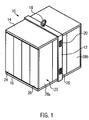
- Fig. 1 shows an elevator car 10 having a car frame (or car sling) 12 carrying a ceiling structure 14 and a floor structure 16.
- the car frame 12 further comprises means for fixing suspension ropes, e.g. a diverting pulley 18 and means 24 for guiding the elevator car along guide rails.
- the elevator car has furthermore other components as e.g. gripping devices which are - like the suspension means 18 or the guiding means 20 - not relevant for the present invention.
- side walls 22 extend in vertical direction.
- On at least one side of the elevator car elevator car doors 24, 26 are provided which are able to open the telescopic manner to allow entrance into the elevator car 10.
- the car doors may deviate from those shown in the figure.
- the embodiment and number of the car doors is not relevant for the invention.
- the side walls on the side and back of the elevator car consist of wall elements 28a, 28b which are connected in their end region whereby the joint between both wall elements 28a, 28b, 28c is connected via a flatbar 30 and bolts 32 in a manner which is described later on in more detail.
- the invention relates to this connection between different side walls 28a, 28b and 28c.
- the wall elements 28a, 28b, 28c are connected to the floor structure 16 and the ceiling structure 14 in a per se known manner.
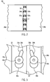
- Fig. 2 shows the joint between two wall elements 28a, 28b of a side wall 22 in a more detailed manner from the inner side of the elevator car.
- the flatbar 30 is a strip of metal sheet extending vertically and covering the surface of both adjacent wall elements 28a, 28b (see also fig. 4 ) which are arranged end-to-end.
- the flatbar 30 has several sets of keyhole perforations 34a, 34b located side by side which are shown in more detail in fig. 3 .
- Each keyhole perforation 34a, 34b has a circular hole 36a, 36b with a larger diameter connected to a longhole or slot 38a, 38b.
- the diameter of the holes 36a, 36b is slightly larger than the diameter of the bolt head 40a, 40b.
- the longholes or slots 38a, 38b of one pair of perforations extend essentially vertically but are slightly inclined in an angle of 5 - 30 degrees relative to each other. Accordingly, the right keyhole perforation 34a, 34b is identical to the left keyhole perforation 34a but mirrored with respect to the center axis 24 of the flatbar 30.
- the flatbar 30 comprises several pairs of the side by side perforations 34a and 34b at different height levels.
- the fixing of two wall elements 28a, 28b is performed as follows:
- the two wall elements 28a, 28b to be connected are located side by side so that their end faces 44a, 44b are in contact. Thereafter bolts 32a, 32b are drilled into the wall elements 28a, 28b in a pattern corresponding to the pattern of the holes in the flatbar.
- the bolts 32a, 32b are not drilled up to the end but to a first mounting position which ensures the movement of the flatbar between the corresponding bolt heads 40a, 40b and the surface of the wall elements 28a, 28b.
- the flat bar is put onto the bolts so that the bolt heads 40a, 40b pass through the holes 36a, 36b of the flatbar.
- the flatbar 30 forms together with the wall elements 28a, 28b a kind of labyrinth seal with also prevents noise from passing through the joint between both wall elements.
- each wall element 28a, 28b consists of two metal sheets 50, 52 between which a noise insulating layer 54 is arranged which is for example stone wool, glass wool or any other noise insulating material. It is also possible that the metal sheets 50, 52 have anchors or fixing elements to improve the connection between the sheet 50, 52 and the noise insulating material 54. The metal sheets 50, 52 may also have perforations which are penetrated by the noise insulating material to improve the mutual connection of these layers. Of course, the layers can be arranged differently from the arrangement shown in fig. 4 .
- Fig. 5 shows the same view as fig. 4 with a different embodiment wherein within the width d the flatbar 30 the thickness of the wall elements 28a, 28b is reduced by the thickness of the flatbar 30 and the thickness of the bolt heads 40a, 40b.
- the surface of the bolt heads 40a, 40b is aligned with the surface 56a, 56b of the wall elements 28a, 28b.
- This facilitates or enables the mounting of decorative panels 58a, 58b, 58c on the inner surface of the wall elements 28a, 28b.
- Decorative panels 58a, 58b, 58c could be made for example from marble, metal or wood according to the desired design of the customer.
- the flatbar 30 and the bolt heads 40a, 40b do not interfere with the mounting of the decorative panels 58b on the inner surface 56a, 56b of the wall elements 28a, 28b.
- Fig. 6 shows the mounting of two wall elements 28b, 28c in the corner region of the elevator car 10, wherein the wall elements 28b, 28c are perpendicular to each other.
- the end face 44b of the first wall element 28b is connected to the surface 56c of the other wall element 28c.
- the joint region between both wall elements 28b, 28c is again covered with a flatbar 30 which is fixed to both wall elements with bolts 32a, 32b in the same manner as it has been discussed in connection with figs. 2 to 4 .
- Fig. 7 and 8 show different patterns of perforations in the flatbar 30.
- the perforations only consist of longholes 340a,b.
- they may consist of keyhole perforations as shown in Fig. 3 .
- the perforations 340a to be connected with the first wall element 28a and the perforations 340b to be connected with the second wall element 28b are vertically offset, so that they are arranged in vertical direction in an alternating succession.
- the perforations 3400 a to be connected with the first wall element 28a and the perforations 3400 b to be connected with the second wall element 28b are vertically offset, but in a way that always two first perforations 3400a of follow two second perforations 3400b in vertical direction, which pattern is repeated along the vertical axis of the flatbar.
- the perforations 341a, 341 b may have any shape which comprises a tilted portion 3410a,b whereby the tilted portion 3410a,b of both perforations 341a,b is mirrored against the center line 42 of the flatbar 30 so that the inclined or tilted portions 3410a,b of both perforations 341a,b are tilted towards each other.
- the tilted portion should be located in both perforations mutually at their opposite sides (i.e. facing away from each other).
- the frame of the elevator car may deviate from the one shown in fig. 1 . Accordingly, it may consist of several parallel multiple frame parts arranged side by side. Furthermore, the connection of the floor and ceiling structures 16, 14 to the frame 12 is not relevant for the invention.
- connection of the wall elements 28a, 28b, 28c to the floor or ceiling structures 16, 14 is performed in line with prior art. Furthermore, the connection of the wall elements 28 to door sections of the car is realized in line with prior art technology and not part of the invention.
- car doors there may be several car doors on different positions of the elevator car for example in the front and back.
- car doors may be turn doors instead of telescopic doors or sliding doors.
- wall elements 28a, 28b, 28c On the inner side of the wall elements decorative panels may be fixed. Furthermore on the outer side of the wall elements 28a, 28b, 28c supporting structures maybe located as e.g. a supporting wall or supporting beams to which the wall elements are fixed in a per se known manner.
Landscapes
- Engineering & Computer Science (AREA)
- Civil Engineering (AREA)
- Structural Engineering (AREA)
- Mechanical Engineering (AREA)
- Architecture (AREA)
- Physics & Mathematics (AREA)
- Electromagnetism (AREA)
- Elevator Door Apparatuses (AREA)
- Cage And Drive Apparatuses For Elevators (AREA)
Description
- The present invention refers to an elevator car comprising a support frame, a floor structure and a ceiling structure, as well as at least one car door and side walls extending between the floor structure and the ceiling structure. As the elevator cars have various sizes according to the specified nominal capacity of an elevator, usually the side walls consist of several wall elements which are aligned end-to-end within one wall. In a corner of the elevator car where one side wall meets another side wall so that the wall elements to be connected are arranged perpendicular to each other the wall elements are arranged end to side. The present invention relates to this basic layout of an elevator car whereby it is particularly directed to high rise elevators or fast driving elevators where the noise of the fast running elevator car increases essentially compared to usual elevators with car velocities about 1 m/s. Elevator cars of such high rise elevators have velocities of two to ten m/s. Accordingly, there is a desire for elevator cars with a good noise insulation.
- The
EP 0 585 945 A1 as well as theUS 2006/0289242 A1 show elevator cars having multi-layer wall elements for better noise insulation. TheUS 4,199,907 discloses a connecting method for non-metal massive panels of elevator cars with flatbars having one vertical and one tilted longhole for the connection of the wall elements. - It is therefore object of the present invention to provide an elevator car with good noise insulation properties which can be easily configured to different cars sizes and which is fast and economic to build.
- The object of the invention is solved with an elevator car according to claim 1. A method for building an elevator car with good noise insulating properties is subject matter of
claim 12. Preferred embodiments of the invention are subject matter of the corresponding sub claims. - According to the invention wall elements are used with good noise insulating properties comprising at least one support material, e.g. panels of metal sheet, plastic panels or fiberboard plates (MDF) and at least one noise insulating material as e.g. stone wool or glass wool. For the wall elements also combinations of several support materials and noise insulating materials may be chosen as desired. The use of wall elements with good insulting properties essentially reduces the noise level in the elevator car even during fast travel of the elevator car in a high rise elevator. Furthermore, a particular joint is provided in the connection area of two adjacent wall elements. Accordingly, one flatbar is used which covers a part of both adjacent wall elements to be connected on both sides of the joint as well as the connecting area itself. This flatbar is connected with fixing elements to at least one of both adjacent wall elements, preferably to both adjacent wall elements. With this solution a kind of labyrinth seal is provided in the joint area between both adjacent wall elements which labyrinth seal has good noise insulting properties. Furthermore, the joint between the two wall elements is not leaking so that it does not allow noise to pass through. Furthermore, in case of any damage single wall elements may be changed or replaced one by one, if needed. The connecting of wall elements by means of the flatbars is fast and no special tools are needed.
- According to the invention the flatbar is connected via fixing elements to both adjacent wall elements which results in a better rigidity of the joint and better noise insulating properties. As fixing elements bolts, particularly punch nuts may be used to fix the flatbar to the wall elements.
- According to the invention the perforations comprise first and second perforations and the first perforations extend over the first of two adjacent wall elements and the second perforations extend over the second of said wall elements. With this construction the flatbar can be easily mounted to both adjacent wall elements.
- The perforations comprise or consist of tilted portions, whereby the tilted portions of the first and second perforations are tilted towards each other. With such a configuration of the perforations it is possible to use the tilted portion for pressing the adjacent wall elements together by moving the flatbar vertically.
- The flatbar maybe any longitudinal band, strip, sheet or bar, e.g. a metal or plastics sheet strip. The flatbar could be embodied as a one-piece element which extends from the floor to the ceiling of the car, e.g. over the total height of the side walls, or it may comprise several parts are mounted above each other in vertical direction. Preferably the flatbar is an element which only extends in one plane and preferably having a thickness between 1 and 5 mm. Such a flatbar is easy to handle and allows a fast and economic joint between adjacent wall elements as it only has to be brought to the surfaces thereof and does not interfere with the inner structure or end structure of the wall elements.
- Preferably the flatbar is mounted on the surface of the wall elements facing the car inside because in this case the side walls can be easily installed from the elevator car. But it is also possible to mount the flatbars on the side of the wall elements facing the shaft. If a very rigid construction is to be achieved the flatbars may be mounted on both sides of the wall elements.
- On the side facing the wall elements the flatbar may comprise a sealing or damping material as e.g. rubber or soft plastics to improve the noise insulation in the area of contact to the wall element surface.
- Preferably the flatbar comprises perforations which are to be penetrated by bolts for fixing the flatbar to one or both adjacent wall elements. This fixing of the flatbar to adjacent wall elements can be performed very easy and fast. By this way the vertical as well as horizontal mutual alignment and fixation of the wall elements is easy to achieve.
- In an embodiment which is easy to manufacture the perforations are embodied as or comprise longholes, in which the bolts can easily slide in the direction of the longitudinal axis of the longholes.
- Preferably, the perforations in the flatbar have a keyhole shape with one larger diameter hole connected to a longhole with a smaller width than the diameter of the hole, which larger diameter hole is larger than the diameter of the bolt heads. In this embodiment of the invention the bolts can be fixed to the wall elements in the perforation pattern of the flatbar without the necessity to arrange the flatbar in mounting position beforehand. After fixing of the bolts in said pattern in the wall elements the flatbar can be arranged in mounting position by simply putting it with the holes over the bolt heads so that the flatbar is held between the bolt heads and the wall elements.
- Preferably in this case the bolts are fixed in a first mounting position which still allows the movement of the flatbar with respect to the wall elements, i.e. the distance of the bolt heads to the wall element surface is slightly larger than the thickness of the flatbar.
- In one alternative longholes of the first perforations are arranged side by side to the longholes of the second perforations. This arrangement is easy to handle. On the other side it is however possible to arrange the longholes of both perforations alternately in vertical direction.
- Preferably several sets of two perforations located side by side are located in the flatbar at different height levels, e.g. 3 to 8 sets to provide a rigid and sealed connection between both adjacent wall elements.
- In an advantageous embodiment of the invention the longholes or the tilted portions of the perforations are extending mainly vertically with a slight tilting angle to each other. The tilting angle may preferably be in a region of 5 to 45 degrees, preferably 10 to 25 degrees. Via this arrangement of the longholes the two adjacent wall elements are pressed together by moving the flatbar in vertical direction so that the already pre-fixed bolts (mounted in the first mounting position) slide along the tilted longholes whereby the mutual distance of the longholes diminishes with the moving distance of the flatbar whereby the two bolts are pressed together by the longholes which also presses the noise insulting wall elements together. By this means a gap the joint between two wall elements can be avoided so that the joint between two adjacent wall elements is not noise leaking and the noise insulting properties of the wall elements are maintained also in the joints of the wall elements.
- It shall be understood that any noise insulting structure panel comprising supporting material as well as insulating material can be used for the wall elements of the elevator car.
- Preferably, the thickness of the wall elements in the area where the flatbar covers the wall element is reduced by the thickness of the flatbar (or by the thickness of the flatbar plus the thickness of the bolt heads) so that the mounted flatbar is in alignment with the surface of the wall elements. Because of this the flatbar (and the bolts) do not hamper the mounting of the decorative panels on the inner side of the wall elements and/or the fixing of the side walls to additional support structures extending between the floor structure and the ceiling structure of the elevator car.
- The invention of course also aims for an elevator comprising at least one elevator car according to the above given specifications.
- The inventive method for mounting the side walls in the elevator car uses an elevator car consisting of a support frame, a floor structure and a ceiling structure, as well as at least one car door and side walls extending between the floor structure and the ceiling structure, wherein the side walls are formed from several wall elements, which are aligned end-to-end or end-to side in corners, wherein flatbars are used for the connection between two adjacent wall elements, which flatbars comprise perforations to be penetrated by bolts to be fixed to the wall elements, wherein the perforations in the flatbar comprise first perforations extending over the first of both adjacent wall elements which are to be connected and second perforations extending over the second of said adjacent wall elements, which perforations comprise longholes or tilted portions of the first and second perforations which are tilted towards each other.
Of course, first the floor and ceiling structures of the elevator car have to be mounted to the car.frame. Then the side walls of the elevator car are built up by connecting wall elements end to end. On this behalf two adjacent wall are located end to end so as to be in contact to each other. Then the bolts are fixed to the wall elements in line with the pattern of the holes in the flatbar in a first mounting position in which the bolt head has a sufficient distance from the wall element surfaces such that the movement of the flatbar with respect to the bolts is still possible. It is irrelevant whether flatbar is provided in its mounting place before or after fixing the bolts in their first mounting position in the wall elements. - After the bolts have been fixed in their first mounting position to the adjacent wall elements and the flatbar is mounted e.g. by putting the holes over the bolt heads, the flatbar is moved in vertical direction so that the flatbar grips the bolts in the longholes. Accordingly, by moving the flatbar in vertical direction so that the bolts travel away from the holes and into the longholes. With the further movement of the flatbar with respect to the wall elements the bolts are pressed by the longholes or tilted portions towards each other which leads to the fact that also the wall elements are pressed towards each other. Via this method a tight joint between two adjacent wall elements is provided which avoids any noise leakage. The vertical movement of the flatbar is stopped when the pressure between two wall elements is in a desired range which ensures that no gap is present any longer between the two wall elements. Afterwards the bolts are tightened (screwed) into a second mounting position wherein the flatbar is tightly (immovable) pressed between the bolt heads and the wall element surfaces. This provides on optimal noise insulating joint with only minor mounting effort. No special tools are needed and the insulation can be performed without building stands on the shaft. The connection of the wall elements to the floor and ceiling structures is performed in line with adapted prior art technology. This also holds true for the mounting of the car doors and other structural elements of the elevator car.
- It shall be clarified that the perforations can also be realized only by longholes without a larger diameter hole connected thereto. In this case the flatbar has to be brought into the mounting position before drilling the bolts into the wall elements.
- It is further possible to place the longholes tilted in different directions vertically offset so that the two different longholes are not located side by side but vertically in different positions.
- It shall be clarified that the flatbar can also be used for the connection of two wall elements in the corner of the car where the two adjacent wall elements are arranged perpendicular to each other. In this case one end of the first wall element is in contact with the surface of the second wall element.
- For the desired tightening pressure effect on the adjacent wall elements the perforations do not need to be longholes, but both perforations needs to have a tilted portion whereby the tilted portions of both perforations are tilted towards each other which allows the bolts pressed together by a vertical movement of the flatbar. Preferably the tilted portion should be located in both perforations mutually at their opposite sides.
- Furthermore, a flatbar may be located at the inner side and/or outer side of the elevator car.
- It shall be understood that the joint line between panels could be other than a vertical one. Further the invention may be applied to other than elevator car panel joints.
- The invention is now described in detail with reference to the embodiments in connection with the enclosed drawings.
- Fig. 1
- shows a perspective schematic view of an elevator car,
- Fig. 2
- shows a detail from
fig. 1 showing two wall elements from the inner side of the elevator car connected by a flatbar, - Fig. 3
- shows an enlarged detail III from
fig. 2 , - Fig. 4
- shows a cross sectional view of the joint region of two adjacent wall elements of a side wall,
- Fig. 5
- shows a cross sectional view of the joint region of two wall elements carrying decorative panels, and
- Fig. 6
- shows the joint region of two wall elements of perpendicular side walls in a car corner,
- Fig. 7
- shows a side view of another embodiment of a joint between two wall elements showing another perforation pattern in a flatbar,
- Fig. 8
- shows a side view of a third embodiment of a joint between two wall elements showing another perforation pattern in a flatbar, and
- Fig. 9
- shows a side view of a fourth embodiment of a joint between two wall elements showing perforations with a tilted portion.
-
Fig. 1 shows anelevator car 10 having a car frame (or car sling) 12 carrying aceiling structure 14 and afloor structure 16. Thecar frame 12 further comprises means for fixing suspension ropes, e.g. a divertingpulley 18 and means 24 for guiding the elevator car along guide rails. The elevator car has furthermore other components as e.g. gripping devices which are - like the suspension means 18 or the guiding means 20 - not relevant for the present invention. Between theceiling structure 14 andfloor structure 16side walls 22 extend in vertical direction. On at least one side of the elevator carelevator car doors elevator car 10. The car doors may deviate from those shown in the figure. The embodiment and number of the car doors is not relevant for the invention. The side walls on the side and back of the elevator car consist ofwall elements wall elements flatbar 30 and bolts 32 in a manner which is described later on in more detail. - The invention relates to this connection between
different side walls wall elements floor structure 16 and theceiling structure 14 in a per se known manner. -
Fig. 2 shows the joint between twowall elements side wall 22 in a more detailed manner from the inner side of the elevator car. Theflatbar 30 is a strip of metal sheet extending vertically and covering the surface of bothadjacent wall elements fig. 4 ) which are arranged end-to-end. - The
flatbar 30 has several sets ofkeyhole perforations fig. 3 . Eachkeyhole perforation circular hole slot - The diameter of the
holes bolt head slots right keyhole perforation left keyhole perforation 34a but mirrored with respect to thecenter axis 24 of theflatbar 30. - As is it derivable from
fig. 2 theflatbar 30 comprises several pairs of the side byside perforations - The fixing of two
wall elements - First the two
wall elements bolts wall elements bolts wall elements bolts wall elements holes bolts different wall elements wall elements bolts flatbar 30 tight (immovable) between the bolt heads 40a, 40b and the surface of thewall elements - On the other side the
flatbar 30 forms together with thewall elements -
Fig. 4 further shows that eachwall element fig. 4 . -
Fig. 5 shows the same view asfig. 4 with a different embodiment wherein within the width d theflatbar 30 the thickness of thewall elements flatbar 30 and the thickness of the bolt heads 40a, 40b. In this arrangement the surface of the bolt heads 40a, 40b is aligned with thesurface wall elements decorative panels wall elements Decorative panels fig. 5 theflatbar 30 and the bolt heads 40a, 40b do not interfere with the mounting of thedecorative panels 58b on theinner surface wall elements -
Fig. 6 shows the mounting of twowall elements elevator car 10, wherein thewall elements end face 44b of thefirst wall element 28b is connected to thesurface 56c of theother wall element 28c. The joint region between bothwall elements flatbar 30 which is fixed to both wall elements withbolts figs. 2 to 4 . -
Fig. 7 and 8 show different patterns of perforations in theflatbar 30. InFig. 7 the perforations only consist of longholes 340a,b. Anyway instead of longholes they may consist of keyhole perforations as shown inFig. 3 . In this embodiment theperforations 340a to be connected with thefirst wall element 28a and theperforations 340b to be connected with thesecond wall element 28b are vertically offset, so that they are arranged in vertical direction in an alternating succession. - In
Fig. 8 theperforations 3400 a to be connected with thefirst wall element 28a and theperforations 3400 b to be connected with thesecond wall element 28b are vertically offset, but in a way that always twofirst perforations 3400a of follow twosecond perforations 3400b in vertical direction, which pattern is repeated along the vertical axis of the flatbar. - According to
Fig. 9 instead of tilted longholes the perforations 341a, 341 b may have any shape which comprises a tiltedportion 3410a,b whereby the tiltedportion 3410a,b of bothperforations 341a,b is mirrored against thecenter line 42 of theflatbar 30 so that the inclined or tiltedportions 3410a,b of bothperforations 341a,b are tilted towards each other. The tilted portion should be located in both perforations mutually at their opposite sides (i.e. facing away from each other). - It should be clear for the skilled person that the above mentioned embodiments are not restricting the invention but the invention may be carried out within the scope of the appended patent claims.
- The frame of the elevator car may deviate from the one shown in
fig. 1 . Accordingly, it may consist of several parallel multiple frame parts arranged side by side. Furthermore, the connection of the floor andceiling structures frame 12 is not relevant for the invention. - The connection of the
wall elements ceiling structures - Of course there may be several car doors on different positions of the elevator car for example in the front and back. Furthermore, the car doors may be turn doors instead of telescopic doors or sliding doors.
- On the inner side of the wall elements decorative panels may be fixed. Furthermore on the outer side of the
wall elements
Claims (12)
- Elevator car (10) comprising a support frame (12), a floor structure (16) and a ceiling structure (14), as well as at least one car door (24) and side walls (22) extending between the floor structure and the ceiling structure, wherein the side walls are formed from several wall elements(28a,b,c), which are aligned end-to-end or end-to side in corners, which wall elements (28a,b,c) are composite panels consisting of at least one support material (50, 52) and at least one noise insulating material (54), characterized in that the elevator car comprises at least one flatbar (30), extending over the surface (56a,b) of both adjacent wall elements, and covering the joint between them, which flatbar (30) is fixed by fixing elements (32a,b) to both adjacent wall elements (28a, b; 28b,c) and comprises perforations (34a,b) to be penetrated by bolts (32a,b), which are fixed to the wall element(s), whereby the perforations (34 a,b) comprise first and second perforations, that the first perforations (34a) extend over the first (28a) of two adjacent wall elements and the second perforations (34b) extend over the second (28b) of said wall elements, and that the perforations are comprising or consisting of tilted portions (38a,b; 340a,b; 3400a,b), whereby the tilted portions of the first and second perforations are tilted towards each other.
- Elevator according to claim 1, characterized in that the tilted portions (38a,b; 340a,b; 3400a,b) are longholes.
- Elevator according to claim 2, characterized in that the perforations (34a,b) in the flatbar (30) have a keyhole shape with one larger diameter hole connected to a longhole with a smaller width than the diameter of the hole, which larger diameter hole is larger than the diameter of the bolt heads (40a,b).
- Elevator car according to any of the preceding claims, characterized in that the longholes (38 a) of the first perforations (34a) are arranged side by side to the longholes (38b) of the second perforations.
- Elevator car according to one of the preceding claims, characterized in that the bolts (32a,b) are punch nuts.
- Elevator car according to one of the preceding claims, characterized in that the support material (50,52) of the wall elements (28a,b,c) is sheet metal.
- Elevator car according to one of the preceding claims, characterized in that the noise insulating material (54) of the wall elements (28a,b,c) is rockwool.
- Elevator car according to one of the preceding claims, characterized in that the flatbar (30) is a strip of metal sheet.
- Elevator car according to one of the preceding claims, characterized in that the region where the flatbar (30) is covering the surface of the adjacent wall elements the thickness of the wall elements is reduced.
- Elevator car according to claim 9 characterized in that the thickness reduction of the wall elements (28a,b) corresponds to the thickness of the flatbar (30) and
optionally also the thickness of the bolt heads. - Elevator comprising an elevator car according to any of the previous claims.
- Method of building up an elevator car (10) consisting of a support frame (12), a floor structure (16) and a ceiling structure (14), as well as at least one car door (24,26) and side walls (22) extending between the floor structure and the ceiling structure, wherein the side walls are formed from several wall elements (28a,b,c), which are aligned end-to-end or end-to side in corners, wherein flatbars (30) are used for the connection between two adjacent wall elements, which flatbars comprise perforations (34a,b; 340a,b; 3400a,b) to be penetrated by bolts (32a,b), which are fixed to the wall element(s), wherein the perforations (34a,b) in the flatbar comprise first perforations (34 a; 340 a; 3400 a) extending over the first (28a) of both wall elements and second perforations (34 b; 340 b; 3400 b) extending over the second (28b) of both wall elements, which longholes (38a,b) of the first and second perforations are tilted towards each other,
in which method a succession of following steps is carried out for the building up of the side walls:- both adjacent walls elements are located end-to end or end-to-side in a corner of two perpendicular extending side walls,- two bolts are fixed to the wall elements into a first fixing position, wherein the bolts are not driven into the wall elements as far as they go to allow the flatbar to be movable with respect to the bolts, whereby the first of both bolts is fixed to the first of the adjacent wall elements and the second of both bolts is fixed to the second of the adjacent wall elements, which two bolts are fixed in a distance which corresponds to the pattern of perforations arranged in the flatbar, whereby,- previously to, during or after the above step the flatbar is put to its mounting location,- the flatbar is moved relative to the bolts in vertical direction, by which movement the adjacent wall elements are caused by the force of the longholes on the bolts to be pressed together,- in a vertical position of the flatbar wherein the pressure force on the wall elements is as desired, the bolts are fixed in a second fixing position in which the flatbar is pressed tightly between the wall elements and the bolt heads.
Applications Claiming Priority (1)
| Application Number | Priority Date | Filing Date | Title |
|---|---|---|---|
| PCT/EP2011/069604 WO2013068034A1 (en) | 2011-11-08 | 2011-11-08 | Elevator car |
Publications (2)
| Publication Number | Publication Date |
|---|---|
| EP2776356A1 EP2776356A1 (en) | 2014-09-17 |
| EP2776356B1 true EP2776356B1 (en) | 2016-04-06 |
Family
ID=45319069
Family Applications (1)
| Application Number | Title | Priority Date | Filing Date |
|---|---|---|---|
| EP11794418.1A Active EP2776356B1 (en) | 2011-11-08 | 2011-11-08 | Elevator car |
Country Status (6)
| Country | Link |
|---|---|
| US (2) | US20140231183A1 (en) |
| EP (1) | EP2776356B1 (en) |
| CN (1) | CN104039676A (en) |
| ES (1) | ES2572212T3 (en) |
| HK (1) | HK1201805A1 (en) |
| WO (1) | WO2013068034A1 (en) |
Families Citing this family (5)
| Publication number | Priority date | Publication date | Assignee | Title |
|---|---|---|---|---|
| WO2013068034A1 (en) * | 2011-11-08 | 2013-05-16 | Kone Corporation | Elevator car |
| CN104955754A (en) * | 2013-02-01 | 2015-09-30 | 通力股份公司 | Elevator system and method for installing an elevator |
| JP6223571B2 (en) * | 2014-07-09 | 2017-11-01 | 三菱電機株式会社 | Elevator cab and its assembly method |
| EP3548412B1 (en) * | 2016-11-29 | 2020-10-07 | Inventio AG | Connecting device and method for connecting a wall element in an elevator car |
| JP7575361B2 (en) * | 2021-08-20 | 2024-10-29 | 株式会社日立製作所 | Elevators and cars |
Family Cites Families (17)
| Publication number | Priority date | Publication date | Assignee | Title |
|---|---|---|---|---|
| US850275A (en) * | 1906-10-27 | 1907-04-16 | George B Staples | Tiling. |
| US2053482A (en) * | 1934-04-21 | 1936-09-08 | Johns Manville | Corner portion of an assembly wall |
| US3303937A (en) * | 1964-09-09 | 1967-02-14 | Interlake Steel Corp | Pallet rack |
| US3392848A (en) * | 1966-06-06 | 1968-07-16 | Interlake Steel Corp | Pallet rack |
| US4199907A (en) * | 1978-08-23 | 1980-04-29 | Westinghouse Electric Corp. | Panel joint |
| US4266386A (en) * | 1979-10-02 | 1981-05-12 | Westinghouse Electric Corp. | Panel joint for assembling panel members |
| US4251969A (en) * | 1979-10-02 | 1981-02-24 | Westinghouse Electric Corp. | Panel joint |
| US4430838A (en) * | 1980-08-07 | 1984-02-14 | Westinghouse Electric Corp. | Panel joints |
| US4435935A (en) * | 1980-10-08 | 1984-03-13 | Perfil En Frio, S.A. (Perfrisa) | Panel joining system |
| US4422277A (en) * | 1981-05-11 | 1983-12-27 | Westinghouse Electric Corp. | Panel Joint |
| FI96410C (en) * | 1992-09-04 | 1996-06-25 | Kone Oy | Wall construction for a lift basket and lift basket |
| US6241109B1 (en) * | 1999-02-05 | 2001-06-05 | Interlake Material Handling, Inc. | Load lock for rack |
| GB9927012D0 (en) * | 1999-11-16 | 2000-01-12 | Steel Construction The | Connecting apparatus |
| US6668514B2 (en) * | 2001-05-18 | 2003-12-30 | Rubbermaid Incorporated | Apparatus and method for connecting adjacent panels |
| DE502006007252D1 (en) * | 2005-05-25 | 2010-08-05 | Inventio Ag | Elevator system with noise reduction device |
| WO2013068034A1 (en) * | 2011-11-08 | 2013-05-16 | Kone Corporation | Elevator car |
| US8801106B2 (en) * | 2012-04-27 | 2014-08-12 | Joy Mm Delaware, Inc. | Cleat for joining chassis modules |
-
2011
- 2011-11-08 WO PCT/EP2011/069604 patent/WO2013068034A1/en not_active Ceased
- 2011-11-08 EP EP11794418.1A patent/EP2776356B1/en active Active
- 2011-11-08 HK HK15102466.4A patent/HK1201805A1/en unknown
- 2011-11-08 CN CN201180076215.6A patent/CN104039676A/en active Pending
- 2011-11-08 ES ES11794418T patent/ES2572212T3/en active Active
-
2014
- 2014-04-24 US US14/260,820 patent/US20140231183A1/en not_active Abandoned
-
2017
- 2017-01-13 US US15/405,777 patent/US10611605B2/en active Active
Also Published As
| Publication number | Publication date |
|---|---|
| CN104039676A (en) | 2014-09-10 |
| US20170121153A1 (en) | 2017-05-04 |
| ES2572212T3 (en) | 2016-05-30 |
| EP2776356A1 (en) | 2014-09-17 |
| HK1201805A1 (en) | 2015-09-11 |
| US10611605B2 (en) | 2020-04-07 |
| WO2013068034A1 (en) | 2013-05-16 |
| US20140231183A1 (en) | 2014-08-21 |
Similar Documents
| Publication | Publication Date | Title |
|---|---|---|
| US10611605B2 (en) | Elevator car including flatbar covering joint between adjacent wall elements | |
| US6138423A (en) | Facing panel | |
| US6381917B1 (en) | Lift door panel | |
| US20080295450A1 (en) | Prefabricated wall panels and a method for manufacturing the same | |
| CN101626970B (en) | Machine mounting in machine roomless elevator system | |
| EP1954548A4 (en) | Composite body for a vehicle | |
| WO2003042467A1 (en) | Frame structure of low-rise building | |
| CA2779808A1 (en) | Modular wall system | |
| CN104229612B (en) | Truss device and escalator or moving walk | |
| KR20140124500A (en) | shielding method of opening wall | |
| KR102466439B1 (en) | Soundproofing assembly for gang form | |
| JP5638383B2 (en) | Elevator car handrail device | |
| JP5054390B2 (en) | Passenger conveyor equipment for building earthquake resistance | |
| KR101273087B1 (en) | Method for installing alc panel to concrete slab | |
| KR20100011971U (en) | Wall structure of elevator cage with low noise function | |
| JP2000063062A (en) | Elevator car | |
| KR200319053Y1 (en) | Pocket frame for sliding door | |
| EP1328460B1 (en) | Supporting structure for elevator guide rails | |
| WO2020217461A1 (en) | Passenger conveyor truss | |
| JP2010184755A (en) | Landing hall unit of elevator | |
| KR102859171B1 (en) | construction panel assembly | |
| CN213802499U (en) | An elevator wood veneer door panel | |
| JP2012172432A (en) | Wooden building's planar structure and construction method thereof | |
| JP3771715B2 (en) | Man conveyor balustrade equipment | |
| EP1953300A2 (en) | Arrangement for joining wood-based construction elements |
Legal Events
| Date | Code | Title | Description |
|---|---|---|---|
| PUAI | Public reference made under article 153(3) epc to a published international application that has entered the european phase |
Free format text: ORIGINAL CODE: 0009012 |
|
| 17P | Request for examination filed |
Effective date: 20140502 |
|
| AK | Designated contracting states |
Kind code of ref document: A1 Designated state(s): AL AT BE BG CH CY CZ DE DK EE ES FI FR GB GR HR HU IE IS IT LI LT LU LV MC MK MT NL NO PL PT RO RS SE SI SK SM TR |
|
| DAX | Request for extension of the european patent (deleted) | ||
| GRAP | Despatch of communication of intention to grant a patent |
Free format text: ORIGINAL CODE: EPIDOSNIGR1 |
|
| INTG | Intention to grant announced |
Effective date: 20151118 |
|
| GRAS | Grant fee paid |
Free format text: ORIGINAL CODE: EPIDOSNIGR3 |
|
| GRAA | (expected) grant |
Free format text: ORIGINAL CODE: 0009210 |
|
| AK | Designated contracting states |
Kind code of ref document: B1 Designated state(s): AL AT BE BG CH CY CZ DE DK EE ES FI FR GB GR HR HU IE IS IT LI LT LU LV MC MK MT NL NO PL PT RO RS SE SI SK SM TR |
|
| REG | Reference to a national code |
Ref country code: GB Ref legal event code: FG4D |
|
| REG | Reference to a national code |
Ref country code: AT Ref legal event code: REF Ref document number: 787586 Country of ref document: AT Kind code of ref document: T Effective date: 20160415 Ref country code: CH Ref legal event code: EP |
|
| REG | Reference to a national code |
Ref country code: IE Ref legal event code: FG4D |
|
| REG | Reference to a national code |
Ref country code: DE Ref legal event code: R096 Ref document number: 602011025035 Country of ref document: DE |
|
| REG | Reference to a national code |
Ref country code: ES Ref legal event code: FG2A Ref document number: 2572212 Country of ref document: ES Kind code of ref document: T3 Effective date: 20160530 |
|
| REG | Reference to a national code |
Ref country code: LT Ref legal event code: MG4D Ref country code: NL Ref legal event code: MP Effective date: 20160406 |
|
| REG | Reference to a national code |
Ref country code: AT Ref legal event code: MK05 Ref document number: 787586 Country of ref document: AT Kind code of ref document: T Effective date: 20160406 |
|
| PG25 | Lapsed in a contracting state [announced via postgrant information from national office to epo] |
Ref country code: NL Free format text: LAPSE BECAUSE OF FAILURE TO SUBMIT A TRANSLATION OF THE DESCRIPTION OR TO PAY THE FEE WITHIN THE PRESCRIBED TIME-LIMIT Effective date: 20160406 |
|
| PG25 | Lapsed in a contracting state [announced via postgrant information from national office to epo] |
Ref country code: FI Free format text: LAPSE BECAUSE OF FAILURE TO SUBMIT A TRANSLATION OF THE DESCRIPTION OR TO PAY THE FEE WITHIN THE PRESCRIBED TIME-LIMIT Effective date: 20160406 Ref country code: LT Free format text: LAPSE BECAUSE OF FAILURE TO SUBMIT A TRANSLATION OF THE DESCRIPTION OR TO PAY THE FEE WITHIN THE PRESCRIBED TIME-LIMIT Effective date: 20160406 Ref country code: NO Free format text: LAPSE BECAUSE OF FAILURE TO SUBMIT A TRANSLATION OF THE DESCRIPTION OR TO PAY THE FEE WITHIN THE PRESCRIBED TIME-LIMIT Effective date: 20160706 Ref country code: IS Free format text: LAPSE BECAUSE OF FAILURE TO SUBMIT A TRANSLATION OF THE DESCRIPTION OR TO PAY THE FEE WITHIN THE PRESCRIBED TIME-LIMIT Effective date: 20160806 Ref country code: PL Free format text: LAPSE BECAUSE OF FAILURE TO SUBMIT A TRANSLATION OF THE DESCRIPTION OR TO PAY THE FEE WITHIN THE PRESCRIBED TIME-LIMIT Effective date: 20160406 |
|
| REG | Reference to a national code |
Ref country code: FR Ref legal event code: PLFP Year of fee payment: 6 |
|
| PG25 | Lapsed in a contracting state [announced via postgrant information from national office to epo] |
Ref country code: SE Free format text: LAPSE BECAUSE OF FAILURE TO SUBMIT A TRANSLATION OF THE DESCRIPTION OR TO PAY THE FEE WITHIN THE PRESCRIBED TIME-LIMIT Effective date: 20160406 Ref country code: AT Free format text: LAPSE BECAUSE OF FAILURE TO SUBMIT A TRANSLATION OF THE DESCRIPTION OR TO PAY THE FEE WITHIN THE PRESCRIBED TIME-LIMIT Effective date: 20160406 Ref country code: PT Free format text: LAPSE BECAUSE OF FAILURE TO SUBMIT A TRANSLATION OF THE DESCRIPTION OR TO PAY THE FEE WITHIN THE PRESCRIBED TIME-LIMIT Effective date: 20160808 Ref country code: HR Free format text: LAPSE BECAUSE OF FAILURE TO SUBMIT A TRANSLATION OF THE DESCRIPTION OR TO PAY THE FEE WITHIN THE PRESCRIBED TIME-LIMIT Effective date: 20160406 Ref country code: LV Free format text: LAPSE BECAUSE OF FAILURE TO SUBMIT A TRANSLATION OF THE DESCRIPTION OR TO PAY THE FEE WITHIN THE PRESCRIBED TIME-LIMIT Effective date: 20160406 Ref country code: GR Free format text: LAPSE BECAUSE OF FAILURE TO SUBMIT A TRANSLATION OF THE DESCRIPTION OR TO PAY THE FEE WITHIN THE PRESCRIBED TIME-LIMIT Effective date: 20160707 Ref country code: RS Free format text: LAPSE BECAUSE OF FAILURE TO SUBMIT A TRANSLATION OF THE DESCRIPTION OR TO PAY THE FEE WITHIN THE PRESCRIBED TIME-LIMIT Effective date: 20160406 |
|
| PG25 | Lapsed in a contracting state [announced via postgrant information from national office to epo] |
Ref country code: BE Free format text: LAPSE BECAUSE OF FAILURE TO SUBMIT A TRANSLATION OF THE DESCRIPTION OR TO PAY THE FEE WITHIN THE PRESCRIBED TIME-LIMIT Effective date: 20160406 |
|
| REG | Reference to a national code |
Ref country code: DE Ref legal event code: R097 Ref document number: 602011025035 Country of ref document: DE |
|
| PG25 | Lapsed in a contracting state [announced via postgrant information from national office to epo] |
Ref country code: DK Free format text: LAPSE BECAUSE OF FAILURE TO SUBMIT A TRANSLATION OF THE DESCRIPTION OR TO PAY THE FEE WITHIN THE PRESCRIBED TIME-LIMIT Effective date: 20160406 Ref country code: SK Free format text: LAPSE BECAUSE OF FAILURE TO SUBMIT A TRANSLATION OF THE DESCRIPTION OR TO PAY THE FEE WITHIN THE PRESCRIBED TIME-LIMIT Effective date: 20160406 Ref country code: RO Free format text: LAPSE BECAUSE OF FAILURE TO SUBMIT A TRANSLATION OF THE DESCRIPTION OR TO PAY THE FEE WITHIN THE PRESCRIBED TIME-LIMIT Effective date: 20160406 Ref country code: CZ Free format text: LAPSE BECAUSE OF FAILURE TO SUBMIT A TRANSLATION OF THE DESCRIPTION OR TO PAY THE FEE WITHIN THE PRESCRIBED TIME-LIMIT Effective date: 20160406 Ref country code: EE Free format text: LAPSE BECAUSE OF FAILURE TO SUBMIT A TRANSLATION OF THE DESCRIPTION OR TO PAY THE FEE WITHIN THE PRESCRIBED TIME-LIMIT Effective date: 20160406 |
|
| PLBE | No opposition filed within time limit |
Free format text: ORIGINAL CODE: 0009261 |
|
| STAA | Information on the status of an ep patent application or granted ep patent |
Free format text: STATUS: NO OPPOSITION FILED WITHIN TIME LIMIT |
|
| PG25 | Lapsed in a contracting state [announced via postgrant information from national office to epo] |
Ref country code: SM Free format text: LAPSE BECAUSE OF FAILURE TO SUBMIT A TRANSLATION OF THE DESCRIPTION OR TO PAY THE FEE WITHIN THE PRESCRIBED TIME-LIMIT Effective date: 20160406 |
|
| 26N | No opposition filed |
Effective date: 20170110 |
|
| PG25 | Lapsed in a contracting state [announced via postgrant information from national office to epo] |
Ref country code: SI Free format text: LAPSE BECAUSE OF FAILURE TO SUBMIT A TRANSLATION OF THE DESCRIPTION OR TO PAY THE FEE WITHIN THE PRESCRIBED TIME-LIMIT Effective date: 20160406 |
|
| REG | Reference to a national code |
Ref country code: CH Ref legal event code: PL |
|
| PG25 | Lapsed in a contracting state [announced via postgrant information from national office to epo] |
Ref country code: CH Free format text: LAPSE BECAUSE OF NON-PAYMENT OF DUE FEES Effective date: 20161130 Ref country code: LI Free format text: LAPSE BECAUSE OF NON-PAYMENT OF DUE FEES Effective date: 20161130 |
|
| REG | Reference to a national code |
Ref country code: IE Ref legal event code: MM4A |
|
| PG25 | Lapsed in a contracting state [announced via postgrant information from national office to epo] |
Ref country code: LU Free format text: LAPSE BECAUSE OF NON-PAYMENT OF DUE FEES Effective date: 20161130 |
|
| REG | Reference to a national code |
Ref country code: FR Ref legal event code: PLFP Year of fee payment: 7 |
|
| PG25 | Lapsed in a contracting state [announced via postgrant information from national office to epo] |
Ref country code: IE Free format text: LAPSE BECAUSE OF NON-PAYMENT OF DUE FEES Effective date: 20161108 |
|
| PG25 | Lapsed in a contracting state [announced via postgrant information from national office to epo] |
Ref country code: HU Free format text: LAPSE BECAUSE OF FAILURE TO SUBMIT A TRANSLATION OF THE DESCRIPTION OR TO PAY THE FEE WITHIN THE PRESCRIBED TIME-LIMIT; INVALID AB INITIO Effective date: 20111108 |
|
| PG25 | Lapsed in a contracting state [announced via postgrant information from national office to epo] |
Ref country code: MK Free format text: LAPSE BECAUSE OF FAILURE TO SUBMIT A TRANSLATION OF THE DESCRIPTION OR TO PAY THE FEE WITHIN THE PRESCRIBED TIME-LIMIT Effective date: 20160406 Ref country code: CY Free format text: LAPSE BECAUSE OF FAILURE TO SUBMIT A TRANSLATION OF THE DESCRIPTION OR TO PAY THE FEE WITHIN THE PRESCRIBED TIME-LIMIT Effective date: 20160406 Ref country code: MC Free format text: LAPSE BECAUSE OF FAILURE TO SUBMIT A TRANSLATION OF THE DESCRIPTION OR TO PAY THE FEE WITHIN THE PRESCRIBED TIME-LIMIT Effective date: 20160406 |
|
| PG25 | Lapsed in a contracting state [announced via postgrant information from national office to epo] |
Ref country code: BG Free format text: LAPSE BECAUSE OF FAILURE TO SUBMIT A TRANSLATION OF THE DESCRIPTION OR TO PAY THE FEE WITHIN THE PRESCRIBED TIME-LIMIT Effective date: 20160406 |
|
| PG25 | Lapsed in a contracting state [announced via postgrant information from national office to epo] |
Ref country code: MT Free format text: LAPSE BECAUSE OF NON-PAYMENT OF DUE FEES Effective date: 20161108 |
|
| PG25 | Lapsed in a contracting state [announced via postgrant information from national office to epo] |
Ref country code: TR Free format text: LAPSE BECAUSE OF FAILURE TO SUBMIT A TRANSLATION OF THE DESCRIPTION OR TO PAY THE FEE WITHIN THE PRESCRIBED TIME-LIMIT Effective date: 20160406 Ref country code: AL Free format text: LAPSE BECAUSE OF FAILURE TO SUBMIT A TRANSLATION OF THE DESCRIPTION OR TO PAY THE FEE WITHIN THE PRESCRIBED TIME-LIMIT Effective date: 20160406 |
|
| P01 | Opt-out of the competence of the unified patent court (upc) registered |
Effective date: 20230525 |
|
| PGFP | Annual fee paid to national office [announced via postgrant information from national office to epo] |
Ref country code: DE Payment date: 20251119 Year of fee payment: 15 |
|
| PGFP | Annual fee paid to national office [announced via postgrant information from national office to epo] |
Ref country code: GB Payment date: 20251121 Year of fee payment: 15 |
|
| PGFP | Annual fee paid to national office [announced via postgrant information from national office to epo] |
Ref country code: IT Payment date: 20251121 Year of fee payment: 15 |
|
| PGFP | Annual fee paid to national office [announced via postgrant information from national office to epo] |
Ref country code: FR Payment date: 20251125 Year of fee payment: 15 |
|
| PGFP | Annual fee paid to national office [announced via postgrant information from national office to epo] |
Ref country code: ES Payment date: 20251229 Year of fee payment: 15 |