EP2775830B1 - Oxygen supply for organ perfusion systems - Google Patents
Oxygen supply for organ perfusion systems Download PDFInfo
- Publication number
- EP2775830B1 EP2775830B1 EP12784314.2A EP12784314A EP2775830B1 EP 2775830 B1 EP2775830 B1 EP 2775830B1 EP 12784314 A EP12784314 A EP 12784314A EP 2775830 B1 EP2775830 B1 EP 2775830B1
- Authority
- EP
- European Patent Office
- Prior art keywords
- oxygen
- perfusion
- air
- fluid
- control
- Prior art date
- Legal status (The legal status is an assumption and is not a legal conclusion. Google has not performed a legal analysis and makes no representation as to the accuracy of the status listed.)
- Active
Links
Images

Classifications
-
- A—HUMAN NECESSITIES
- A01—AGRICULTURE; FORESTRY; ANIMAL HUSBANDRY; HUNTING; TRAPPING; FISHING
- A01N—PRESERVATION OF BODIES OF HUMANS OR ANIMALS OR PLANTS OR PARTS THEREOF; BIOCIDES, e.g. AS DISINFECTANTS, AS PESTICIDES OR AS HERBICIDES; PEST REPELLANTS OR ATTRACTANTS; PLANT GROWTH REGULATORS
- A01N1/00—Preservation of bodies of humans or animals, or parts thereof
- A01N1/10—Preservation of living parts
- A01N1/14—Mechanical aspects of preservation; Apparatus or containers therefor
- A01N1/142—Apparatus
- A01N1/143—Apparatus for organ perfusion
-
- A—HUMAN NECESSITIES
- A01—AGRICULTURE; FORESTRY; ANIMAL HUSBANDRY; HUNTING; TRAPPING; FISHING
- A01N—PRESERVATION OF BODIES OF HUMANS OR ANIMALS OR PLANTS OR PARTS THEREOF; BIOCIDES, e.g. AS DISINFECTANTS, AS PESTICIDES OR AS HERBICIDES; PEST REPELLANTS OR ATTRACTANTS; PLANT GROWTH REGULATORS
- A01N1/00—Preservation of bodies of humans or animals, or parts thereof
- A01N1/10—Preservation of living parts
-
- A—HUMAN NECESSITIES
- A61—MEDICAL OR VETERINARY SCIENCE; HYGIENE
- A61M—DEVICES FOR INTRODUCING MEDIA INTO, OR ONTO, THE BODY; DEVICES FOR TRANSDUCING BODY MEDIA OR FOR TAKING MEDIA FROM THE BODY; DEVICES FOR PRODUCING OR ENDING SLEEP OR STUPOR
- A61M1/00—Suction or pumping devices for medical purposes; Devices for carrying-off, for treatment of, or for carrying-over, body-liquids; Drainage systems
- A61M1/14—Dialysis systems; Artificial kidneys; Blood oxygenators ; Reciprocating systems for treatment of body fluids, e.g. single needle systems for hemofiltration or pheresis
- A61M1/16—Dialysis systems; Artificial kidneys; Blood oxygenators ; Reciprocating systems for treatment of body fluids, e.g. single needle systems for hemofiltration or pheresis with membranes
- A61M1/1698—Blood oxygenators with or without heat-exchangers
-
- A—HUMAN NECESSITIES
- A61—MEDICAL OR VETERINARY SCIENCE; HYGIENE
- A61M—DEVICES FOR INTRODUCING MEDIA INTO, OR ONTO, THE BODY; DEVICES FOR TRANSDUCING BODY MEDIA OR FOR TAKING MEDIA FROM THE BODY; DEVICES FOR PRODUCING OR ENDING SLEEP OR STUPOR
- A61M1/00—Suction or pumping devices for medical purposes; Devices for carrying-off, for treatment of, or for carrying-over, body-liquids; Drainage systems
- A61M1/36—Other treatment of blood in a by-pass of the natural circulatory system, e.g. temperature adaptation, irradiation ; Extra-corporeal blood circuits
- A61M1/3621—Extra-corporeal blood circuits
- A61M1/3623—Means for actively controlling temperature of blood
Definitions
- the present invention relates to perfusion systems for bodily organs, for example human organs, such as the liver, pancreas, kidney, small bowel, but also other organs including non-human organs.
- bodily organs for example human organs, such as the liver, pancreas, kidney, small bowel, but also other organs including non-human organs.
- the invention relates to the supply of oxygen for such systems and the control of the content of perfusion fluids in such systems.
- the system typically comprises a reservoir for perfusion fluid (or perfusate), which may be blood or another perfusion solution, and a circuit for circulating the fluid through the organ.
- perfusion fluid or perfusate
- the circuit typically also comprises an oxygenator or other device for adding oxygen, carbon dioxide, or other substances into the blood, from a source which typically comprises a pressurized gas cylinder.
- US 2010/0330547 A1 discloses an organ perfusion system, wherein the preserving gas used to perfuse the organ may be administered to the organ as a gas/liquid solution or as a gas/gas mixture.
- the preserving gas may be oxygen or carbon dioxide, and where the preserving gas is oxygen, it may be generated in situ using an oxygen concentrator.
- An adjustable flow valve may adjust the rate at which ambient air is to be mixed with pure oxygen so that a desired oxygen concentration may be obtained.
- the present invention provides a perfusion system for the perfusion of an organ, the system comprising: a perfusion fluid circuit for circulating perfusion fluid (perfusate) through the organ; oxygenation means for adding oxygen into the perfusion fluid; an oxygen supply arranged to supply oxygen to the oxygenation means, wherein the oxygen supply comprises an oxygen concentrator, the oxygen concentrator comprising an inlet arranged to receive gas in the form of air, which may be at atmospheric pressure, and nitrogen extraction means arranged to extract nitrogen from the gas thereby to increase the oxygen concentration of the gas; an air supply arranged to supply air to the oxygenation means; carbon dioxide measuring means arranged to measure the carbon dioxide content in the perfusion fluid; an air control valve arranged to control the flow rate of air from the air supply to the oxygenation means; an oxygen control valve arranged to control the flow rate of oxygen from the oxygen concentrator to the oxygenation means; oxygen measuring means arranged to measure the oxygen content in the perfusion fluid; and control means arranged to monitor the measured oxygen content and to control the oxygen control valve in response to the measured oxygen content thereby to
- the oxygen concentrator may comprise an outlet from which gas can be fed to the oxygenator.
- the oxygen concentrator may comprise a compressor arranged to pump the gas through the nitrogen extraction means.
- the pump may be arranged to pump gas to the oxygenation means. Some of that gas may be arranged to bypass the nitrogen extraction means, for example passing through a separate supply duct, to provide the gas necessary to control CO 2 in the perfusate.
- the control means is arranged to control the air control valve in response to the measured carbon dioxide content.
- the oxygenation means is arranged both to add oxygen into the fluid and extract carbon dioxide from the fluid, and therefore serves as a gas content adjustment means for adjusting both oxygen and carbon dioxide level.
- the system may further comprise an analysis duct through which the fluid can flow to bypass the organ.
- the measuring means may be arranged to measure the fluid in the analysis duct.
- the measuring means may be arranged to operate during perfusion of the organ.
- the control means may be arranged to operate during perfusion of the organ to maintain the target range or ranges during perfusion.
- the range may be defined by upper and lower limits, or just a lower limit, or just an upper limit.
- the system may further comprise a user interface arranged to enable a user to input at least one limit of said range, or at least one of said ranges.
- the user interface may be arranged to enable a user to input one or both limits of the target oxygen content, or one or both limits of the target carbon dioxide content.
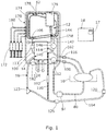
- a perfusion system generally comprises a sling 10 in which an organ can be supported, a fluid reservoir 12, an oxygenator 14, and a perfusion circuit 16 arranged to circulate fluid between the reservoir, the organ, and the oxygenator during perfusion.
- a controller 18 is arranged to control the functioning of the system as will be described in more detail below.
- An ascites duct 80 is connected at one end to a drainage hole in the bottom of the sling 10 and at the other end to an ascites return port 82 in the top of the fluid reservoir 12.
- An ascites pump 84 is provided in the ascites duct 80 to pump ascites from the sling 10 back up into the reservoir 12.
- the perfusion circuit 16 further comprises a portal duct 100, a hepatic artery duct 102 and an inferior vena cava (IVC) duct 104.
- the portal duct 100 has one end connected to an outlet port 106 in the fluid reservoir and the other end attached to a portal vein connector 108.
- a flow control valve in the form of a pinch valve 112 having a variable degree of opening, is provided in the portal duct 100 and is connected to the controller 18.
- the controller 18 is arranged to vary the degree of opening of the pinch valve 112 so as to control the rate of flow of fluid from the reservoir 12 to the portal vein of a liver.
- the hepatic artery duct 102 has one end connected to a first outlet port 114 of the oxygenator 14 and the other end attached to a hepatic artery connector 116.
- a flow sensor 113 is arranged to measure the rate of fluid flow in the portal vein duct 100 and is arranged to output a signal indicative of the flow rate of fluid in the portal vein 100. The output of the flow sensor 113 is connected to the controller 18 which can therefore monitor the flow rate in the portal vein duct 100.
- the IVC duct 104 has one end attached to a vena cava connector 120 and its other end connected to an inlet port 124 of the oxygenator 14.
- a pump 123 is provided in the IVC duct 104 having its inlet connected to the vena cava connector 120 and its outlet connected to the inlet port 124 of the oxygenator 14.
- the pump 123 is arranged to pump fluid from the IVC duct 104 into the oxygenator 124.
- the pump 123 is a variable speed pump and is connected to, and controlled by, the controller 18.
- An IVC flow sensor 125 is arranged to measure the rate of fluid flow in the IVC duct 104 and is arranged to output a signal indicative of the flow rate of fluid in the IVC duct 104.
- the output of the flow sensor 125 is connected to the controller 18 which can therefore monitor the flow rate in the vena cava duct.
- the controller 18 is also arranged to measure the flow rate in the arterial duct 102 by determining the difference between the flow measured by the flow sensor 125 in the IVC duct 104 and that measured by flow sensor 113 in the portal vein duct 100.
- the oxygenator 14 has a second outlet port 140 which is connected by a pressure control duct 142 to a further port 144 in the fluid reservoir 12.
- a flow control valve in the form of a pinch valve 146, having a variable degree of opening, is provided in the pressure control duct 142 and is connected to the controller 18 so that the controller can vary the degree of opening of the pinch valve 146 thereby to control the return flow of fluid from the oxygenator 14 to the reservoir 12.
- This together with the pump 123, is used to control the pressure of fluid flowing to the organ through the hepatic artery duct 102, as well as the pressure of the fluid in the IVC duct 104 flowing away form the organ.
- the oxygenator which is shown schematically, comprises a through duct 150 arranged to carry fluid from the inlet port 124 to the two outlet ports 114, 140.
- An oxygen chamber 152 has an inlet port 154 for connection to an oxygen supply and an air supply, and an outlet or vent port 156 for venting the oxygen and air from the oxygen chamber.
- a vent 158 is connected at its lower end to the through duct 150 and extends upward so that its upper end is approximately level with the top of the reservoir 12. This vent 158 is closable, and is arranged to be opened during filling of the fluid circuit to vent air from the oxygenator, but is closed during perfusion.
- a permeable membrane 160 between the oxygen chamber 152 and the through duct 150 allows oxygen in the oxygen chamber 152 to oxygenate fluid, which may be blood, in the through duct 150.
- the membrane 160 also allows CO 2 in the perfusate to pass out of the perfusate through the membrane into the air.
- a water chamber or duct 162 is also connected to a water inlet port 164 and a water outlet port 166, and is separated from the through duct 150 by a thermally conductive wall 168. This allows water, or another suitable thermal control fluid, to be circulated through the oxygenator 14 to control the temperature of the perfusion fluid.
- a heater 167 is provided to heat water entering the oxygenator via the water inlet port 164, and a thermometer 169 is provided to measure the temperature of the perfusate flowing out of the oxygenator into the hepatic artery duct 102.
- the heater 167 and the thermometer 169 are connected to the controller 18 which is arranged to measure and monitor the temperature of the perfusate supplied to the organ and control the heater 167 so as to maintain the perfusate temperature at a desired level, for example within a target temperature range.
- a bubbler can be used, instead of the type of oxygenator shown in Figure 2 , which bubbles the concentrated oxygen through the perfusate.
- the system can include separate devices one for each gas.
- a nutrient control circuit 170 comprises a set of syringes 172, in this case four, each containing a respective nutrient, and a nutrient feed duct 174 which has one end connected to a separate fluid reservoir 176 and the other end connected to a nutrient inlet port 178 in the top of the main fluid reservoir 12.
- Each of the syringes 172 is connected to the nutrient feed duct 174 by a respective nutrient input duct 180.
- a nutrient pump 182 is arranged in the nutrient feed duct 174 to pump fluid through the nutrient feed duct from the nutrient feed reservoir 176 into the main reservoir 12 via the nutrient inlet port 178.
- the pump 182 and the syringes 172 are controlled by the controller 18 so that the rate at which each of the nutrients is fed into the reservoir 12 is controlled.
- a small diameter fluid analysis duct 190 has one end connected to the IVC duct 104, upstream of the pump 123, and in this case downstream of the IVC flow sensor 125, and the other end connected to the pressure control duct 142 so that fluid can flow from the pressure control duct 142 to the IVC duct 104, bypassing the organ.
- a blood gas analyser (BGA) 192 is arranged to measure various parameters of the fluid flowing through the fluid analysis duct 190.
- the BGA 192 is arranged to measure the oxygen content and the carbon dioxide content of the fluid flowing through it. Other parameters can also be measured and monitored.
- the BGA 192 is connected to the controller 18 and arranged to output signals each of which is indicative of the value of one of the parameters it measures, and the controller 18 is arranged to receive those signals so that the parameters can be monitored by the controller 18.
- the signals therefore include an oxygen level signal, a CO 2 level signal, and a glucose level signal in this embodiment.
- the oxygen supply to the oxygenator inlet 154 is provided by an oxygen concentrator 200.
- This comprises a pair of zeolite towers 202, 204, an air inlet 206 arranged to receive gas in the form of air at atmospheric pressure, a compressor 208 arranged in the inlet to compress the incoming air, and a two way switch valve 210 operable to control the flow of incoming air into the zeolite towers 202, 204.
- Each of the towers 202, 204 has an outlet 212, 214 and these are connected together to form a single outlet from the oxygen concentrator which in turn is connected to the inlet 154 of the oxygenator.
- the zeolite In use, as the compressed air flows through the zeolite towers 202, 204, the zeolite extracts nitrogen from the air which increases the concentration of oxygen in the gas.
- the nitrogen leaves the towers via vents 216, and the gas leaving the concentrator 200 through its outlet, which comprises concentrated oxygen as well as some nitrogen and traces of other gases, is fed to the oxygenator inlet 154.
- a proportional valve 224 in the outlet from the oxygen concentrator is arranged to control the flow rate of gas, and hence oxygen, from the oxygen concentrator 200 to the oxygenator 14.
- the proportional valve 224 is connected to, and controlled by, the controller 18 so that the controller can control the flow rate of oxygen into the oxygenator 14.
- the air supply to the oxygenator inlet 154 is provided by a further compressor 220 which has an inlet 222 arranged to receive air at atmospheric pressure.
- a further proportional valve 226 in the outlet from the compressor 220 is connected to and controlled by the controller 18, so that the controller can control the flow rate of air from the compressor 220 to the oxygenator. Because there are separate proportional valves for the oxygen and air supplies, the flow rates of oxygen and air can be controlled, at least to some extent, independently of each other.
- the second compressor 220 is omitted and the output from the first compressor 208 is connected both to the oxygen concentrator 200 and through a separate air duct via the second proportional valve 226 to the oxygenator gas inlet.
- the single compressor 208 therefore provides the pressure for the oxygen and air supplies, the flow rates of which are controlled independently by their respective flow control valves 224, 226.
- perfusate fluid flow through the liver is controlled by the controller 18 which is arranged to control the pressure in the hepatic artery duct 102 and the IVC duct 104 to maintain them at approximately constant pressures, allowing the liver to regulate the flow rate of fluid through it itself.
- the controller 18 is arranged to monitor the pressure in the hepatic artery duct 100 by monitoring the output signal from the pressure sensor 136 and the pressure in the vena cava duct 104 by monitoring the output of the pressure sensor 138, and to control the perfusion pump 123 and the pinch valve 146 in the pressure control duct 142 so as to maintain the measured pressures, i.e. the pressure sensor output signals, at respective set levels, or within respective ranges.
- the oxygen level in the perfusate fluid is also controlled by the controller 18 during perfusion. While most of the oxygenated perfusate from the oxygenator outlet 114 flows through the hepatic artery duct 102, a small proportion of it is diverted through the fluid analysis duct 190 and through the BGA 192.
- the BGA 192 detects the level of oxygen in the perfusate, which is monitored by the controller 18.
- the controller 18 is arranged to control the pressure and flow rate of oxygen supplied by the oxygen concentrator 200 to the oxygenator by controlling the pump 208 and the two-way valve 210 of the oxygen concentrator 200, so as to control the rate at which perfusate is oxygenated in the oxygenator 100.
- the controller 18 is arranged to keep the oxygen level of the blood at a predetermined level or within a predetermined range.
- the controller 18 has a memory in which a target level or range of the oxygen content can be stored and the controller is arranged to compare the measured level with the stored level to determine how the oxygen level needs to be controlled.
- the complete range will be defined, with upper and lower limits of oxygen content.
- the range may be defined only by a lower limit, in which case the controller can be arranged to trigger a process to add oxygen to provide a step increase in oxygen content when the oxygen content falls below that level.
- the stored target level or range can be selected and altered by means of a user input which in this case is in the form of a graphic user interface (GUI) 17 connected to the controller 18.
- the GUI 17 is also arranged to display various information including the values of various operating parameters of the system, which in this embodiment include oxygen level, CO 2 level, glucose level, temperature, and flow rate of the perfusate.
- the carbon dioxide (CO 2 ) level in the perfusate is also monitored and controlled by the controller 18 in a similar way to the oxygen level, except that it is arranged to increase the flow rate of air to reduce the CO 2 level, decrease the flow rate of air to increase the CO 2 level.
- the controller 18 is arranged to continuously use the CO 2 level signal from the BGA 192 to measure the CO 2 level in the perfusate, compare it with target levels stored in memory in the controller 18, and control the air flow control valve 226 to control the flow rate of air into the oxygenator 16. Varying the flow rate of air varies the rate at which CO 2 is extracted from the perfusate, so controlling the air flow rate through the oxygenator can be used to control the CO 2 level in the perfusate.
- the flow rate of air is increased so as to increase the rate at which CO 2 is extracted from the perfusate. If the CO 2 level is below the target range, then the air flow rate is decreased to decrease the rate at which CO 2 is extracted from the perfusate.
- the target CO 2 level or range can also be set and adjusted by a user by means of the user input 17.
- the system is arranged for perfusion of a liver.
- organs such as the kidney can be perfused, and such organs only have one artery to supply blood to the organ and one vein to take blood from the organ. Therefore in another embodiment the system is the same as that described above except that the portal vein duct is completely omitted.
Landscapes
- Life Sciences & Earth Sciences (AREA)
- Health & Medical Sciences (AREA)
- Engineering & Computer Science (AREA)
- Dentistry (AREA)
- General Health & Medical Sciences (AREA)
- Wood Science & Technology (AREA)
- Zoology (AREA)
- Environmental Sciences (AREA)
- External Artificial Organs (AREA)
- Agricultural Chemicals And Associated Chemicals (AREA)
Description
- The present invention relates to perfusion systems for bodily organs, for example human organs, such as the liver, pancreas, kidney, small bowel, but also other organs including non-human organs. In particular the invention relates to the supply of oxygen for such systems and the control of the content of perfusion fluids in such systems.
- It is known, for example from
EP 1 168 913 , to provide a system for extracorporeal organ perfusion in which a human or non-human organ can be preserved, for example prior to transplant into a patient. The system typically comprises a reservoir for perfusion fluid (or perfusate), which may be blood or another perfusion solution, and a circuit for circulating the fluid through the organ. The circuit typically also comprises an oxygenator or other device for adding oxygen, carbon dioxide, or other substances into the blood, from a source which typically comprises a pressurized gas cylinder. -
US 2010/0330547 A1 discloses an organ perfusion system, wherein the preserving gas used to perfuse the organ may be administered to the organ as a gas/liquid solution or as a gas/gas mixture. The preserving gas may be oxygen or carbon dioxide, and where the preserving gas is oxygen, it may be generated in situ using an oxygen concentrator. An adjustable flow valve may adjust the rate at which ambient air is to be mixed with pure oxygen so that a desired oxygen concentration may be obtained. - The present invention provides a perfusion system for the perfusion of an organ, the system comprising: a perfusion fluid circuit for circulating perfusion fluid (perfusate) through the organ; oxygenation means for adding oxygen into the perfusion fluid; an oxygen supply arranged to supply oxygen to the oxygenation means, wherein the oxygen supply comprises an oxygen concentrator, the oxygen concentrator comprising an inlet arranged to receive gas in the form of air, which may be at atmospheric pressure, and nitrogen extraction means arranged to extract nitrogen from the gas thereby to increase the oxygen concentration of the gas; an air supply arranged to supply air to the oxygenation means; carbon dioxide measuring means arranged to measure the carbon dioxide content in the perfusion fluid; an air control valve arranged to control the flow rate of air from the air supply to the oxygenation means; an oxygen control valve arranged to control the flow rate of oxygen from the oxygen concentrator to the oxygenation means; oxygen measuring means arranged to measure the oxygen content in the perfusion fluid; and control means arranged to monitor the measured oxygen content and to control the oxygen control valve in response to the measured oxygen content thereby to maintain the oxygen content within a target range, and to monitor the measured carbon dioxide content and to control the air control valve in response to the measured carbon dioxide content thereby to maintain the carbon dioxide content within a target range.
- The oxygen concentrator may comprise an outlet from which gas can be fed to the oxygenator.
- The oxygen concentrator may comprise a compressor arranged to pump the gas through the nitrogen extraction means. The pump may be arranged to pump gas to the oxygenation means. Some of that gas may be arranged to bypass the nitrogen extraction means, for example passing through a separate supply duct, to provide the gas necessary to control CO2 in the perfusate.
- The control means is arranged to control the air control valve in response to the measured carbon dioxide content. In this case the oxygenation means is arranged both to add oxygen into the fluid and extract carbon dioxide from the fluid, and therefore serves as a gas content adjustment means for adjusting both oxygen and carbon dioxide level.
- The system may further comprise an analysis duct through which the fluid can flow to bypass the organ. The measuring means may be arranged to measure the fluid in the analysis duct.
- The measuring means may be arranged to operate during perfusion of the organ. The control means may be arranged to operate during perfusion of the organ to maintain the target range or ranges during perfusion.
- In each case where a target range is referred to above, the range may be defined by upper and lower limits, or just a lower limit, or just an upper limit.
- The system may further comprise a user interface arranged to enable a user to input at least one limit of said range, or at least one of said ranges. For example the user interface may be arranged to enable a user to input one or both limits of the target oxygen content, or one or both limits of the target carbon dioxide content.
- Preferred embodiments of the present invention will now be described by way of example only with reference to the accompanying drawings.
-
-
Figure 1 is a schematic diagram of a perfusion system according to an embodiment of the invention; -
Figure 2 is a schematic diagram of an oxygenator forming part of the system of -
Figure 1 , and; -
Figure 3 is a schematic diagram of an oxygen concentrator forming part of the system ofFigure 1 . - Referring to
Figure 1 , a perfusion system according to an embodiment of the invention generally comprises asling 10 in which an organ can be supported, afluid reservoir 12, anoxygenator 14, and aperfusion circuit 16 arranged to circulate fluid between the reservoir, the organ, and the oxygenator during perfusion. Acontroller 18 is arranged to control the functioning of the system as will be described in more detail below. - An
ascites duct 80 is connected at one end to a drainage hole in the bottom of thesling 10 and at the other end to anascites return port 82 in the top of thefluid reservoir 12. An ascites pump 84 is provided in theascites duct 80 to pump ascites from thesling 10 back up into thereservoir 12. - The
perfusion circuit 16 further comprises aportal duct 100, ahepatic artery duct 102 and an inferior vena cava (IVC)duct 104. Theportal duct 100 has one end connected to anoutlet port 106 in the fluid reservoir and the other end attached to aportal vein connector 108. A flow control valve, in the form of apinch valve 112 having a variable degree of opening, is provided in theportal duct 100 and is connected to thecontroller 18. Thecontroller 18 is arranged to vary the degree of opening of thepinch valve 112 so as to control the rate of flow of fluid from thereservoir 12 to the portal vein of a liver. Thehepatic artery duct 102 has one end connected to afirst outlet port 114 of theoxygenator 14 and the other end attached to ahepatic artery connector 116. Aflow sensor 113 is arranged to measure the rate of fluid flow in theportal vein duct 100 and is arranged to output a signal indicative of the flow rate of fluid in theportal vein 100. The output of theflow sensor 113 is connected to thecontroller 18 which can therefore monitor the flow rate in theportal vein duct 100. TheIVC duct 104 has one end attached to avena cava connector 120 and its other end connected to aninlet port 124 of theoxygenator 14. Apump 123 is provided in theIVC duct 104 having its inlet connected to thevena cava connector 120 and its outlet connected to theinlet port 124 of theoxygenator 14. Thepump 123 is arranged to pump fluid from theIVC duct 104 into theoxygenator 124. Thepump 123 is a variable speed pump and is connected to, and controlled by, thecontroller 18. AnIVC flow sensor 125 is arranged to measure the rate of fluid flow in theIVC duct 104 and is arranged to output a signal indicative of the flow rate of fluid in theIVC duct 104. The output of theflow sensor 125 is connected to thecontroller 18 which can therefore monitor the flow rate in the vena cava duct. Thecontroller 18 is also arranged to measure the flow rate in thearterial duct 102 by determining the difference between the flow measured by theflow sensor 125 in theIVC duct 104 and that measured byflow sensor 113 in theportal vein duct 100. - The
oxygenator 14 has asecond outlet port 140 which is connected by apressure control duct 142 to afurther port 144 in thefluid reservoir 12. A flow control valve, in the form of apinch valve 146, having a variable degree of opening, is provided in thepressure control duct 142 and is connected to thecontroller 18 so that the controller can vary the degree of opening of thepinch valve 146 thereby to control the return flow of fluid from theoxygenator 14 to thereservoir 12. This, together with thepump 123, is used to control the pressure of fluid flowing to the organ through thehepatic artery duct 102, as well as the pressure of the fluid in theIVC duct 104 flowing away form the organ. - Referring to
Figure 2 , the oxygenator, which is shown schematically, comprises a through duct 150 arranged to carry fluid from theinlet port 124 to the twooutlet ports oxygen chamber 152 has aninlet port 154 for connection to an oxygen supply and an air supply, and an outlet or ventport 156 for venting the oxygen and air from the oxygen chamber. Avent 158 is connected at its lower end to the through duct 150 and extends upward so that its upper end is approximately level with the top of thereservoir 12. Thisvent 158 is closable, and is arranged to be opened during filling of the fluid circuit to vent air from the oxygenator, but is closed during perfusion. Apermeable membrane 160 between theoxygen chamber 152 and the through duct 150 allows oxygen in theoxygen chamber 152 to oxygenate fluid, which may be blood, in the through duct 150. Themembrane 160 also allows CO2 in the perfusate to pass out of the perfusate through the membrane into the air. A water chamber orduct 162 is also connected to awater inlet port 164 and awater outlet port 166, and is separated from the through duct 150 by a thermallyconductive wall 168. This allows water, or another suitable thermal control fluid, to be circulated through theoxygenator 14 to control the temperature of the perfusion fluid. Aheater 167 is provided to heat water entering the oxygenator via thewater inlet port 164, and athermometer 169 is provided to measure the temperature of the perfusate flowing out of the oxygenator into thehepatic artery duct 102. Theheater 167 and thethermometer 169 are connected to thecontroller 18 which is arranged to measure and monitor the temperature of the perfusate supplied to the organ and control theheater 167 so as to maintain the perfusate temperature at a desired level, for example within a target temperature range. - It will be appreciated that other devices can be used for adding oxygen and carbon dioxide into the perfusate. For example a bubbler can be used, instead of the type of oxygenator shown in
Figure 2 , which bubbles the concentrated oxygen through the perfusate. Also, instead of one device which brings a gas into contact with the perfusate and in which the oxygen and carbon dioxide content of the gas are controlled, the system can include separate devices one for each gas. - Referring back to
Figure 1 , anutrient control circuit 170 comprises a set ofsyringes 172, in this case four, each containing a respective nutrient, and anutrient feed duct 174 which has one end connected to aseparate fluid reservoir 176 and the other end connected to anutrient inlet port 178 in the top of themain fluid reservoir 12. Each of thesyringes 172 is connected to thenutrient feed duct 174 by a respectivenutrient input duct 180. Anutrient pump 182 is arranged in thenutrient feed duct 174 to pump fluid through the nutrient feed duct from thenutrient feed reservoir 176 into themain reservoir 12 via thenutrient inlet port 178. Thepump 182 and thesyringes 172 are controlled by thecontroller 18 so that the rate at which each of the nutrients is fed into thereservoir 12 is controlled. - A small diameter
fluid analysis duct 190 has one end connected to theIVC duct 104, upstream of thepump 123, and in this case downstream of theIVC flow sensor 125, and the other end connected to thepressure control duct 142 so that fluid can flow from thepressure control duct 142 to theIVC duct 104, bypassing the organ. A blood gas analyser (BGA) 192 is arranged to measure various parameters of the fluid flowing through thefluid analysis duct 190. In this embodiment theBGA 192 is arranged to measure the oxygen content and the carbon dioxide content of the fluid flowing through it. Other parameters can also be measured and monitored. TheBGA 192 is connected to thecontroller 18 and arranged to output signals each of which is indicative of the value of one of the parameters it measures, and thecontroller 18 is arranged to receive those signals so that the parameters can be monitored by thecontroller 18. The signals therefore include an oxygen level signal, a CO2 level signal, and a glucose level signal in this embodiment. - Referring to
Figure 3 , the oxygen supply to theoxygenator inlet 154 is provided by anoxygen concentrator 200. This comprises a pair ofzeolite towers air inlet 206 arranged to receive gas in the form of air at atmospheric pressure, acompressor 208 arranged in the inlet to compress the incoming air, and a twoway switch valve 210 operable to control the flow of incoming air into the zeolite towers 202, 204. Each of thetowers outlet inlet 154 of the oxygenator. In use, as the compressed air flows through the zeolite towers 202, 204, the zeolite extracts nitrogen from the air which increases the concentration of oxygen in the gas. The nitrogen leaves the towers viavents 216, and the gas leaving theconcentrator 200 through its outlet, which comprises concentrated oxygen as well as some nitrogen and traces of other gases, is fed to theoxygenator inlet 154. Aproportional valve 224 in the outlet from the oxygen concentrator is arranged to control the flow rate of gas, and hence oxygen, from theoxygen concentrator 200 to theoxygenator 14. Theproportional valve 224 is connected to, and controlled by, thecontroller 18 so that the controller can control the flow rate of oxygen into theoxygenator 14. The air supply to theoxygenator inlet 154 is provided by afurther compressor 220 which has aninlet 222 arranged to receive air at atmospheric pressure. A furtherproportional valve 226 in the outlet from thecompressor 220 is connected to and controlled by thecontroller 18, so that the controller can control the flow rate of air from thecompressor 220 to the oxygenator. Because there are separate proportional valves for the oxygen and air supplies, the flow rates of oxygen and air can be controlled, at least to some extent, independently of each other. - In a modification to the arrangement of
Figure 3 , thesecond compressor 220 is omitted and the output from thefirst compressor 208 is connected both to theoxygen concentrator 200 and through a separate air duct via the secondproportional valve 226 to the oxygenator gas inlet. Thesingle compressor 208 therefore provides the pressure for the oxygen and air supplies, the flow rates of which are controlled independently by their respectiveflow control valves - Referring back to
Figure 1 , perfusate fluid flow through the liver is controlled by thecontroller 18 which is arranged to control the pressure in thehepatic artery duct 102 and theIVC duct 104 to maintain them at approximately constant pressures, allowing the liver to regulate the flow rate of fluid through it itself. To do this, thecontroller 18 is arranged to monitor the pressure in thehepatic artery duct 100 by monitoring the output signal from the pressure sensor 136 and the pressure in thevena cava duct 104 by monitoring the output of the pressure sensor 138, and to control theperfusion pump 123 and thepinch valve 146 in thepressure control duct 142 so as to maintain the measured pressures, i.e. the pressure sensor output signals, at respective set levels, or within respective ranges. - The oxygen level in the perfusate fluid is also controlled by the
controller 18 during perfusion. While most of the oxygenated perfusate from theoxygenator outlet 114 flows through thehepatic artery duct 102, a small proportion of it is diverted through thefluid analysis duct 190 and through theBGA 192. TheBGA 192 detects the level of oxygen in the perfusate, which is monitored by thecontroller 18. Thecontroller 18 is arranged to control the pressure and flow rate of oxygen supplied by theoxygen concentrator 200 to the oxygenator by controlling thepump 208 and the two-way valve 210 of theoxygen concentrator 200, so as to control the rate at which perfusate is oxygenated in theoxygenator 100. Thecontroller 18 is arranged to keep the oxygen level of the blood at a predetermined level or within a predetermined range. Thecontroller 18 has a memory in which a target level or range of the oxygen content can be stored and the controller is arranged to compare the measured level with the stored level to determine how the oxygen level needs to be controlled. Typically the complete range will be defined, with upper and lower limits of oxygen content. However the range may be defined only by a lower limit, in which case the controller can be arranged to trigger a process to add oxygen to provide a step increase in oxygen content when the oxygen content falls below that level. The stored target level or range can be selected and altered by means of a user input which in this case is in the form of a graphic user interface (GUI) 17 connected to thecontroller 18. TheGUI 17 is also arranged to display various information including the values of various operating parameters of the system, which in this embodiment include oxygen level, CO2 level, glucose level, temperature, and flow rate of the perfusate. - The carbon dioxide (CO2) level in the perfusate is also monitored and controlled by the
controller 18 in a similar way to the oxygen level, except that it is arranged to increase the flow rate of air to reduce the CO2 level, decrease the flow rate of air to increase the CO2 level. Thecontroller 18 is arranged to continuously use the CO2 level signal from theBGA 192 to measure the CO2 level in the perfusate, compare it with target levels stored in memory in thecontroller 18, and control the airflow control valve 226 to control the flow rate of air into theoxygenator 16. Varying the flow rate of air varies the rate at which CO2 is extracted from the perfusate, so controlling the air flow rate through the oxygenator can be used to control the CO2 level in the perfusate. If the CO2 level is above the target range, then the flow rate of air is increased so as to increase the rate at which CO2 is extracted from the perfusate. If the CO2 level is below the target range, then the air flow rate is decreased to decrease the rate at which CO2 is extracted from the perfusate. The target CO2 level or range can also be set and adjusted by a user by means of theuser input 17. - In the embodiment described above, the system is arranged for perfusion of a liver. However other organs such as the kidney can be perfused, and such organs only have one artery to supply blood to the organ and one vein to take blood from the organ. Therefore in another embodiment the system is the same as that described above except that the portal vein duct is completely omitted.
Claims (6)
- A perfusion system for the perfusion of an organ, the system comprising: a perfusion fluid circuit (16) for circulating perfusion fluid through the organ; oxygenation means (14) for adding oxygen into the perfusion fluid; an oxygen supply arranged to supply oxygen to the oxygenation means, wherein the oxygen supply comprises an oxygen concentrator (200), the oxygen concentrator comprising an inlet (206) arranged to receive gas in the form of air, and nitrogen extraction means (216) arranged to extract nitrogen from the gas thereby to increase the oxygen concentration of the gas; an air supply arranged to supply air to the oxygenation means whereby the oxygenation means can extract carbon dioxide from the perfusion fluid; carbon dioxide measuring means arranged to measure the carbon dioxide content in the perfusion fluid; an air control valve (226) arranged to control the flow rate of air from the air supply to the oxygenation means; an oxygen control valve (224) arranged to control the flow rate of oxygen from the oxygen concentrator to the oxygenation means; oxygen measuring means arranged to measure the oxygen content in the perfusion fluid; and control means (18) arranged to monitor the measured oxygen content and to control the oxygen control valve in response to the measured oxygen content thereby to maintain the oxygen content within a target range, and to monitor the measured carbon dioxide content and to control the air control valve in response to the measured carbon dioxide content thereby to maintain the carbon dioxide content within a target range.
- A perfusion system according to claim 1, wherein the oxygen concentrator comprises a compressor (208) arranged to pump the gas through the nitrogen extraction means, and to pump gas to the oxygenation means, bypassing the nitrogen extraction means, thereby to form the air supply.
- A perfusion system according to claim 1 or claim 2 further comprising a user interface (17) arranged to enable a user to input at least one limit of said target ranges, or at least one of said target ranges.
- A perfusion system according to any preceding claim further comprising an analysis duct (190) through which the fluid can flow to bypass the organ, wherein the measuring means is arranged to measure the fluid in the analysis duct.
- A perfusion system according to any preceding claim wherein the measuring means is arranged to operate during perfusion of the organ and the control means is arranged to operate during perfusion of the organ to maintain the target range or ranges.
- A perfusion system according to claim 2 wherein the output from the compressor (208) is connected both to the oxygen concentrator (200) and through a separate air duct via the air control valve (226) to the gas inlet (154) of the oxygenation means.
Applications Claiming Priority (2)
| Application Number | Priority Date | Filing Date | Title |
|---|---|---|---|
| GBGB1119420.6A GB201119420D0 (en) | 2011-11-10 | 2011-11-10 | Oxygen supply for organ perfusion systems |
| PCT/GB2012/052783 WO2013068753A1 (en) | 2011-11-10 | 2012-11-08 | Oxygen supply for organ perfusion systems |
Publications (2)
| Publication Number | Publication Date |
|---|---|
| EP2775830A1 EP2775830A1 (en) | 2014-09-17 |
| EP2775830B1 true EP2775830B1 (en) | 2019-01-02 |
Family
ID=45421572
Family Applications (1)
| Application Number | Title | Priority Date | Filing Date |
|---|---|---|---|
| EP12784314.2A Active EP2775830B1 (en) | 2011-11-10 | 2012-11-08 | Oxygen supply for organ perfusion systems |
Country Status (8)
| Country | Link |
|---|---|
| US (1) | US10362780B2 (en) |
| EP (1) | EP2775830B1 (en) |
| CN (1) | CN104039136B (en) |
| BR (1) | BR112014011279A2 (en) |
| CA (1) | CA2855341C (en) |
| ES (1) | ES2711104T3 (en) |
| GB (2) | GB201119420D0 (en) |
| WO (1) | WO2013068753A1 (en) |
Families Citing this family (30)
| Publication number | Priority date | Publication date | Assignee | Title |
|---|---|---|---|---|
| US8304181B2 (en) | 2004-10-07 | 2012-11-06 | Transmedics, Inc. | Method for ex-vivo organ care and for using lactate as an indication of donor organ status |
| NZ591524A (en) | 2004-10-07 | 2012-09-28 | Transmedics Inc | Method for timing pulsatile flow of normothermic perfusate to the heart in ex-vivo organ care |
| US12010987B2 (en) | 2004-10-07 | 2024-06-18 | Transmedics, Inc. | Systems and methods for ex-vivo organ care and for using lactate as an indication of donor organ status |
| US9078428B2 (en) | 2005-06-28 | 2015-07-14 | Transmedics, Inc. | Systems, methods, compositions and solutions for perfusing an organ |
| US9457179B2 (en) | 2007-03-20 | 2016-10-04 | Transmedics, Inc. | Systems for monitoring and applying electrical currents in an organ perfusion system |
| US8420380B2 (en) | 2008-01-31 | 2013-04-16 | Transmedics, Inc. | Systems and methods for ex vivo lung care |
| EP2704560B1 (en) | 2011-04-14 | 2022-04-06 | Transmedics, Inc. | Organ care solution for ex-vivo machine perfusion of donor lungs |
| US20140017665A1 (en) * | 2012-07-10 | 2014-01-16 | Lifeline Scientific, Inc. | Organ transporter with oxygen generation |
| CN106030295B (en) * | 2013-12-20 | 2019-10-01 | 皇家飞利浦有限公司 | Sensing system and oxygen separator including sensing system |
| US10076112B2 (en) | 2014-06-02 | 2018-09-18 | Transmedic, Inc. | Ex vivo organ care system |
| WO2015187968A1 (en) | 2014-06-04 | 2015-12-10 | Sonescence, Inc. | Systems and methods for therapeutic agent delivery |
| EP4378496B1 (en) * | 2014-11-19 | 2026-05-06 | University of Maryland, Baltimore | Artificial lung system and its methods of use |
| WO2016090498A1 (en) | 2014-12-12 | 2016-06-16 | Freed Darren | Apparatus and method for organ perfusion |
| CN106178159A (en) * | 2015-03-30 | 2016-12-07 | Estor股份公司 | Equipment and corresponding carbon dioxide for extracorporeal blood treatment are removed and oxygenate method |
| EP3347084B1 (en) | 2015-09-09 | 2020-11-11 | Transmedics, Inc. | Aortic cannula for ex vivo organ care system |
| CA3025673A1 (en) | 2016-05-30 | 2017-12-07 | Tevosol, Inc. | Apparatus and method for ex vivo lung ventilation with a varying exterior pressure |
| EP3487295B1 (en) | 2016-07-22 | 2020-11-04 | ETH Zürich | Perfusion loop assembly for an ex-vivo liver perfusion |
| WO2018201138A1 (en) * | 2017-04-28 | 2018-11-01 | Lifeline Scientific, Inc. | Organ transporter with supplemental oxygenation system |
| EP3513653A1 (en) * | 2018-01-19 | 2019-07-24 | ETH Zürich | Perfusion loop assembly for an ex-vivo liver perfusion and a method for ex-vivo liver perfusion |
| US12225900B2 (en) | 2018-01-19 | 2025-02-18 | Eth Zurich | Perfusion loop assembly for an ex-vivo liver perfusion and a method for ex-vivo liver perfusion |
| CN108157352A (en) * | 2018-02-11 | 2018-06-15 | 广东顺德工业设计研究院(广东顺德创新设计研究院) | Multiple organ one perfusion equipment |
| CN109730054B (en) * | 2019-01-30 | 2021-09-21 | 广东丁沃生医疗器械有限公司 | Gas delivery system for liver perfusion |
| US12356982B2 (en) | 2019-03-14 | 2025-07-15 | Lifeline Scientific, Inc. | Oxygenator device |
| CN211294426U (en) * | 2019-03-22 | 2020-08-18 | 天一阁医疗科技(广州)有限公司 | Organ perfusion teaching and training system |
| CN114375159A (en) | 2019-09-13 | 2022-04-19 | 生命线科学有限公司 | Organ container with oxygenation option |
| GB202018460D0 (en) | 2020-11-24 | 2021-01-06 | Organox Ltd | Precision oxygen flow control for organ perfusion systems |
| EP4373271A4 (en) * | 2021-07-22 | 2025-06-04 | Biomedinnovations, Llc | Portable device for the perfusion of multi-role organs |
| IT202100022808A1 (en) * | 2021-09-03 | 2023-03-03 | Maria Cecilia Hospital S P A | DEVICE FOR THE TREATMENT OF BIOLOGICAL TISSUES |
| CN113975505B (en) * | 2021-11-08 | 2023-12-19 | 中山大学中山眼科中心 | Extracorporeal circulation system for eyeball perfusion |
| JP2023088347A (en) * | 2021-12-15 | 2023-06-27 | 株式会社Screenホールディングス | Organ preservation device and organ preservation method |
Family Cites Families (38)
| Publication number | Priority date | Publication date | Assignee | Title |
|---|---|---|---|---|
| US3772153A (en) | 1969-04-02 | 1973-11-13 | Air Liquide | Apparatus for the preservation of animal or human organs in living condition |
| US4493692A (en) * | 1982-09-29 | 1985-01-15 | Reed Charles C | Blood gas concentration control apparatus and method |
| SE8206430L (en) | 1982-11-12 | 1984-05-13 | Meteve Ab | DEVICE SOURCE DEVICE |
| US5157930A (en) | 1991-04-22 | 1992-10-27 | Mcghee Samuel C | Organ preservation apparatus |
| DE4320198C1 (en) * | 1993-06-18 | 1994-07-14 | Fresenius Ag | Blood gas exchange appts. |
| US5462416A (en) | 1993-12-22 | 1995-10-31 | Baxter International Inc. | Peristaltic pump tube cassette for blood processing systems |
| WO1996029865A1 (en) | 1995-03-27 | 1996-10-03 | Organ, Inc. | Organ evaluation and resuscitation device and method |
| DE19702098B4 (en) * | 1997-01-22 | 2004-02-12 | HORUS medizinische Artikel und Geräte | Mobile heart-lung machine |
| DE19715152A1 (en) | 1997-04-11 | 1998-10-15 | Udo Prof Dr Franz | Equipment for perfusing limbs to extend live state during transplantation |
| US6642045B1 (en) | 1997-04-14 | 2003-11-04 | Breonics, Inc. | System for exsanguinous metabolic support of an organ or tissue |
| US6673594B1 (en) * | 1998-09-29 | 2004-01-06 | Organ Recovery Systems | Apparatus and method for maintaining and/or restoring viability of organs |
| GB9908335D0 (en) | 1999-04-12 | 1999-06-09 | Univ Cambridge Tech | Methods and means for extracorporeal organ perfusion |
| US6582953B2 (en) | 1999-04-14 | 2003-06-24 | Breonics, Inc. | Organ chamber for exsanguinous metabolic support system |
| DE10015807C2 (en) * | 2000-03-24 | 2002-09-19 | Mediport Biotech Gmbh | Process and device for maintaining vital organs, extremities and tissue flaps by perfusion |
| WO2002020982A2 (en) * | 2000-09-07 | 2002-03-14 | Savage Enterprises, Inc. | Igniter for internal combustion engines operating over a wide range of air fuel ratios |
| AU2001294922A1 (en) | 2000-10-02 | 2002-04-15 | Thomas F. Cannon | Automated bioculture and bioculture experiments system |
| FR2822540B1 (en) | 2001-03-23 | 2004-09-10 | Labmetrix Technologies Iett Sa | AUTOMATED VOLUME MEASUREMENT PROCESS |
| US20040170950A1 (en) * | 2002-09-12 | 2004-09-02 | Prien Samuel D. | Organ preservation apparatus and methods |
| WO2004089085A2 (en) | 2003-04-04 | 2004-10-21 | Organ Recovery Systems, Inc. | Device for separating gas from a liquid path |
| WO2004089235A2 (en) | 2003-04-04 | 2004-10-21 | Organ Recovery Systems, Inc. | Methods and apparatus for perfusion, diagnosis, storage and/or transport of an organ or tissue |
| US7601268B2 (en) | 2003-05-27 | 2009-10-13 | Haemonetics Corporation | Continuous blood filtration and method of use |
| US7504201B2 (en) | 2004-04-05 | 2009-03-17 | Organ Recovery Systems | Method for perfusing an organ and for isolating cells from the organ |
| US8741555B2 (en) | 2004-05-14 | 2014-06-03 | Organ Recovery Systems, Inc. | Apparatus and method for perfusion and determining the viability of an organ |
| US8304181B2 (en) | 2004-10-07 | 2012-11-06 | Transmedics, Inc. | Method for ex-vivo organ care and for using lactate as an indication of donor organ status |
| NZ591524A (en) | 2004-10-07 | 2012-09-28 | Transmedics Inc | Method for timing pulsatile flow of normothermic perfusate to the heart in ex-vivo organ care |
| US7225085B2 (en) | 2005-02-25 | 2007-05-29 | The Regents Of The University Of California | Precision gas flow meter |
| WO2006118990A2 (en) | 2005-04-29 | 2006-11-09 | Transplan, Inc. | Method and device for organ perfusion |
| US7491261B2 (en) * | 2005-06-27 | 2009-02-17 | Wearair Oxygen, Inc. | Process and apparatus for generating and delivering an enriched gas fraction |
| US8753435B2 (en) * | 2006-04-03 | 2014-06-17 | Ric Investments, Llc | Portable oxygen concentrator |
| EP3677118A1 (en) | 2006-04-19 | 2020-07-08 | Transmedics, Inc. | Systems for ex vivo organ care |
| SE531453C2 (en) | 2007-07-06 | 2009-04-07 | Xenodevice Ab | Organ evaluation and preservation system |
| US8420380B2 (en) | 2008-01-31 | 2013-04-16 | Transmedics, Inc. | Systems and methods for ex vivo lung care |
| US8329450B2 (en) | 2008-08-01 | 2012-12-11 | Biomedinnovations, Llc | Methods and apparatus for organ support |
| US20100143192A1 (en) | 2008-12-04 | 2010-06-10 | Therox, Inc. | Method and device for combined detection of bubbles and flow rate in a system for enriching a bodily fluid with a gas |
| US10091985B2 (en) * | 2009-06-18 | 2018-10-09 | Giner, Inc. | Perfusing an organ with an in situ generated gas |
| US9357764B2 (en) * | 2009-06-18 | 2016-06-07 | Giner, Inc. | System for fluid perfusion of biological matter comprising tissue |
| US9320269B2 (en) | 2009-09-25 | 2016-04-26 | John Brassil | Organ preservation system |
| EP2717680A1 (en) | 2011-06-09 | 2014-04-16 | Lifeline Scientific, Inc. | Data record for organ transport and/or storage, comprising biomarker and events information |
-
2011
- 2011-11-10 GB GBGB1119420.6A patent/GB201119420D0/en not_active Ceased
-
2012
- 2012-11-08 WO PCT/GB2012/052783 patent/WO2013068753A1/en not_active Ceased
- 2012-11-08 GB GB1408212.7A patent/GB2509875B/en active Active
- 2012-11-08 CA CA2855341A patent/CA2855341C/en active Active
- 2012-11-08 BR BR112014011279A patent/BR112014011279A2/en active IP Right Grant
- 2012-11-08 EP EP12784314.2A patent/EP2775830B1/en active Active
- 2012-11-08 ES ES12784314T patent/ES2711104T3/en active Active
- 2012-11-08 US US14/357,078 patent/US10362780B2/en active Active
- 2012-11-08 CN CN201280066672.1A patent/CN104039136B/en active Active
Non-Patent Citations (1)
| Title |
|---|
| None * |
Also Published As
| Publication number | Publication date |
|---|---|
| ES2711104T3 (en) | 2019-04-30 |
| BR112014011279A2 (en) | 2017-05-02 |
| GB2509875B (en) | 2017-07-19 |
| GB201119420D0 (en) | 2011-12-21 |
| CN104039136B (en) | 2016-08-24 |
| GB2509875A (en) | 2014-07-16 |
| EP2775830A1 (en) | 2014-09-17 |
| CA2855341C (en) | 2019-06-04 |
| CN104039136A (en) | 2014-09-10 |
| US10362780B2 (en) | 2019-07-30 |
| GB201408212D0 (en) | 2014-06-25 |
| US20150004677A1 (en) | 2015-01-01 |
| CA2855341A1 (en) | 2013-05-16 |
| WO2013068753A1 (en) | 2013-05-16 |
Similar Documents
| Publication | Publication Date | Title |
|---|---|---|
| US10362780B2 (en) | Oxygen supply for organ perfusion systems | |
| US11540508B2 (en) | Organ perfusion systems | |
| US12295361B2 (en) | Organ perfusion device | |
| CN205124849U (en) | Separation liver normal atmospheric temperature or low control by temperature change temperature perfusion device | |
| EP3226929B1 (en) | Ventilation system | |
| US20110003275A1 (en) | System and method for organ evaluation and preservation | |
| US8329450B2 (en) | Methods and apparatus for organ support | |
| US20250188424A1 (en) | Hypothermic Liver Perfusion Preservation Device and Method | |
| JPH0374302A (en) | Organ storage system | |
| US12543728B2 (en) | Precision oxygen flow control for organ perfusion systems | |
| RU2855495C1 (en) | Device for controlled cultivation of isolated liver with ability to change pressure parameters and gas composition inside organ chamber | |
| WO2024058775A1 (en) | Systems and methods for oxygenating blood, passive oxygenation circuits, and neonatal extracorporeal support systems | |
| US8173414B2 (en) | Sulfide perfusion apparatus | |
| CN206933133U (en) | A kind of oxygen carrying device for casting |
Legal Events
| Date | Code | Title | Description |
|---|---|---|---|
| PUAI | Public reference made under article 153(3) epc to a published international application that has entered the european phase |
Free format text: ORIGINAL CODE: 0009012 |
|
| 17P | Request for examination filed |
Effective date: 20140509 |
|
| AK | Designated contracting states |
Kind code of ref document: A1 Designated state(s): AL AT BE BG CH CY CZ DE DK EE ES FI FR GB GR HR HU IE IS IT LI LT LU LV MC MK MT NL NO PL PT RO RS SE SI SK SM TR |
|
| DAX | Request for extension of the european patent (deleted) | ||
| GRAP | Despatch of communication of intention to grant a patent |
Free format text: ORIGINAL CODE: EPIDOSNIGR1 |
|
| STAA | Information on the status of an ep patent application or granted ep patent |
Free format text: STATUS: GRANT OF PATENT IS INTENDED |
|
| INTG | Intention to grant announced |
Effective date: 20180703 |
|
| GRAS | Grant fee paid |
Free format text: ORIGINAL CODE: EPIDOSNIGR3 |
|
| GRAA | (expected) grant |
Free format text: ORIGINAL CODE: 0009210 |
|
| STAA | Information on the status of an ep patent application or granted ep patent |
Free format text: STATUS: THE PATENT HAS BEEN GRANTED |
|
| RBV | Designated contracting states (corrected) |
Designated state(s): AL AT BE BG CH CY CZ DE DK EE ES FI FR GR HR HU IE IS IT LI LT LU LV MC MK MT NL NO PL PT RO RS SE SI SK SM TR |
|
| AK | Designated contracting states |
Kind code of ref document: B1 Designated state(s): AL AT BE BG CH CY CZ DE DK EE ES FI FR GR HR HU IE IS IT LI LT LU LV MC MK MT NL NO PL PT RO RS SE SI SK SM TR |
|
| REG | Reference to a national code |
Ref country code: CH Ref legal event code: EP Ref country code: AT Ref legal event code: REF Ref document number: 1083254 Country of ref document: AT Kind code of ref document: T Effective date: 20190115 |
|
| REG | Reference to a national code |
Ref country code: IE Ref legal event code: FG4D |
|
| REG | Reference to a national code |
Ref country code: DE Ref legal event code: R096 Ref document number: 602012055449 Country of ref document: DE |
|
| REG | Reference to a national code |
Ref country code: ES Ref legal event code: FG2A Ref document number: 2711104 Country of ref document: ES Kind code of ref document: T3 Effective date: 20190430 |
|
| REG | Reference to a national code |
Ref country code: NL Ref legal event code: MP Effective date: 20190102 |
|
| REG | Reference to a national code |
Ref country code: LT Ref legal event code: MG4D |
|
| REG | Reference to a national code |
Ref country code: AT Ref legal event code: MK05 Ref document number: 1083254 Country of ref document: AT Kind code of ref document: T Effective date: 20190102 |
|
| PG25 | Lapsed in a contracting state [announced via postgrant information from national office to epo] |
Ref country code: NL Free format text: LAPSE BECAUSE OF FAILURE TO SUBMIT A TRANSLATION OF THE DESCRIPTION OR TO PAY THE FEE WITHIN THE PRESCRIBED TIME-LIMIT Effective date: 20190102 |
|
| PG25 | Lapsed in a contracting state [announced via postgrant information from national office to epo] |
Ref country code: FI Free format text: LAPSE BECAUSE OF FAILURE TO SUBMIT A TRANSLATION OF THE DESCRIPTION OR TO PAY THE FEE WITHIN THE PRESCRIBED TIME-LIMIT Effective date: 20190102 Ref country code: NO Free format text: LAPSE BECAUSE OF FAILURE TO SUBMIT A TRANSLATION OF THE DESCRIPTION OR TO PAY THE FEE WITHIN THE PRESCRIBED TIME-LIMIT Effective date: 20190402 Ref country code: PL Free format text: LAPSE BECAUSE OF FAILURE TO SUBMIT A TRANSLATION OF THE DESCRIPTION OR TO PAY THE FEE WITHIN THE PRESCRIBED TIME-LIMIT Effective date: 20190102 Ref country code: LT Free format text: LAPSE BECAUSE OF FAILURE TO SUBMIT A TRANSLATION OF THE DESCRIPTION OR TO PAY THE FEE WITHIN THE PRESCRIBED TIME-LIMIT Effective date: 20190102 Ref country code: PT Free format text: LAPSE BECAUSE OF FAILURE TO SUBMIT A TRANSLATION OF THE DESCRIPTION OR TO PAY THE FEE WITHIN THE PRESCRIBED TIME-LIMIT Effective date: 20190502 Ref country code: SE Free format text: LAPSE BECAUSE OF FAILURE TO SUBMIT A TRANSLATION OF THE DESCRIPTION OR TO PAY THE FEE WITHIN THE PRESCRIBED TIME-LIMIT Effective date: 20190102 |
|
| PG25 | Lapsed in a contracting state [announced via postgrant information from national office to epo] |
Ref country code: LV Free format text: LAPSE BECAUSE OF FAILURE TO SUBMIT A TRANSLATION OF THE DESCRIPTION OR TO PAY THE FEE WITHIN THE PRESCRIBED TIME-LIMIT Effective date: 20190102 Ref country code: RS Free format text: LAPSE BECAUSE OF FAILURE TO SUBMIT A TRANSLATION OF THE DESCRIPTION OR TO PAY THE FEE WITHIN THE PRESCRIBED TIME-LIMIT Effective date: 20190102 Ref country code: IS Free format text: LAPSE BECAUSE OF FAILURE TO SUBMIT A TRANSLATION OF THE DESCRIPTION OR TO PAY THE FEE WITHIN THE PRESCRIBED TIME-LIMIT Effective date: 20190502 Ref country code: BG Free format text: LAPSE BECAUSE OF FAILURE TO SUBMIT A TRANSLATION OF THE DESCRIPTION OR TO PAY THE FEE WITHIN THE PRESCRIBED TIME-LIMIT Effective date: 20190402 Ref country code: GR Free format text: LAPSE BECAUSE OF FAILURE TO SUBMIT A TRANSLATION OF THE DESCRIPTION OR TO PAY THE FEE WITHIN THE PRESCRIBED TIME-LIMIT Effective date: 20190403 Ref country code: HR Free format text: LAPSE BECAUSE OF FAILURE TO SUBMIT A TRANSLATION OF THE DESCRIPTION OR TO PAY THE FEE WITHIN THE PRESCRIBED TIME-LIMIT Effective date: 20190102 |
|
| REG | Reference to a national code |
Ref country code: DE Ref legal event code: R097 Ref document number: 602012055449 Country of ref document: DE |
|
| PG25 | Lapsed in a contracting state [announced via postgrant information from national office to epo] |
Ref country code: AT Free format text: LAPSE BECAUSE OF FAILURE TO SUBMIT A TRANSLATION OF THE DESCRIPTION OR TO PAY THE FEE WITHIN THE PRESCRIBED TIME-LIMIT Effective date: 20190102 Ref country code: DK Free format text: LAPSE BECAUSE OF FAILURE TO SUBMIT A TRANSLATION OF THE DESCRIPTION OR TO PAY THE FEE WITHIN THE PRESCRIBED TIME-LIMIT Effective date: 20190102 Ref country code: EE Free format text: LAPSE BECAUSE OF FAILURE TO SUBMIT A TRANSLATION OF THE DESCRIPTION OR TO PAY THE FEE WITHIN THE PRESCRIBED TIME-LIMIT Effective date: 20190102 Ref country code: SK Free format text: LAPSE BECAUSE OF FAILURE TO SUBMIT A TRANSLATION OF THE DESCRIPTION OR TO PAY THE FEE WITHIN THE PRESCRIBED TIME-LIMIT Effective date: 20190102 Ref country code: AL Free format text: LAPSE BECAUSE OF FAILURE TO SUBMIT A TRANSLATION OF THE DESCRIPTION OR TO PAY THE FEE WITHIN THE PRESCRIBED TIME-LIMIT Effective date: 20190102 Ref country code: CZ Free format text: LAPSE BECAUSE OF FAILURE TO SUBMIT A TRANSLATION OF THE DESCRIPTION OR TO PAY THE FEE WITHIN THE PRESCRIBED TIME-LIMIT Effective date: 20190102 Ref country code: RO Free format text: LAPSE BECAUSE OF FAILURE TO SUBMIT A TRANSLATION OF THE DESCRIPTION OR TO PAY THE FEE WITHIN THE PRESCRIBED TIME-LIMIT Effective date: 20190102 |
|
| PLBE | No opposition filed within time limit |
Free format text: ORIGINAL CODE: 0009261 |
|
| STAA | Information on the status of an ep patent application or granted ep patent |
Free format text: STATUS: NO OPPOSITION FILED WITHIN TIME LIMIT |
|
| PG25 | Lapsed in a contracting state [announced via postgrant information from national office to epo] |
Ref country code: SM Free format text: LAPSE BECAUSE OF FAILURE TO SUBMIT A TRANSLATION OF THE DESCRIPTION OR TO PAY THE FEE WITHIN THE PRESCRIBED TIME-LIMIT Effective date: 20190102 |
|
| 26N | No opposition filed |
Effective date: 20191003 |
|
| PG25 | Lapsed in a contracting state [announced via postgrant information from national office to epo] |
Ref country code: SI Free format text: LAPSE BECAUSE OF FAILURE TO SUBMIT A TRANSLATION OF THE DESCRIPTION OR TO PAY THE FEE WITHIN THE PRESCRIBED TIME-LIMIT Effective date: 20190102 |
|
| PG25 | Lapsed in a contracting state [announced via postgrant information from national office to epo] |
Ref country code: TR Free format text: LAPSE BECAUSE OF FAILURE TO SUBMIT A TRANSLATION OF THE DESCRIPTION OR TO PAY THE FEE WITHIN THE PRESCRIBED TIME-LIMIT Effective date: 20190102 |
|
| REG | Reference to a national code |
Ref country code: CH Ref legal event code: PL |
|
| PG25 | Lapsed in a contracting state [announced via postgrant information from national office to epo] |
Ref country code: LU Free format text: LAPSE BECAUSE OF NON-PAYMENT OF DUE FEES Effective date: 20191108 Ref country code: CH Free format text: LAPSE BECAUSE OF NON-PAYMENT OF DUE FEES Effective date: 20191130 Ref country code: LI Free format text: LAPSE BECAUSE OF NON-PAYMENT OF DUE FEES Effective date: 20191130 Ref country code: MC Free format text: LAPSE BECAUSE OF FAILURE TO SUBMIT A TRANSLATION OF THE DESCRIPTION OR TO PAY THE FEE WITHIN THE PRESCRIBED TIME-LIMIT Effective date: 20190102 |
|
| PG25 | Lapsed in a contracting state [announced via postgrant information from national office to epo] |
Ref country code: IE Free format text: LAPSE BECAUSE OF NON-PAYMENT OF DUE FEES Effective date: 20191108 |
|
| PG25 | Lapsed in a contracting state [announced via postgrant information from national office to epo] |
Ref country code: CY Free format text: LAPSE BECAUSE OF FAILURE TO SUBMIT A TRANSLATION OF THE DESCRIPTION OR TO PAY THE FEE WITHIN THE PRESCRIBED TIME-LIMIT Effective date: 20190102 |
|
| PG25 | Lapsed in a contracting state [announced via postgrant information from national office to epo] |
Ref country code: MT Free format text: LAPSE BECAUSE OF FAILURE TO SUBMIT A TRANSLATION OF THE DESCRIPTION OR TO PAY THE FEE WITHIN THE PRESCRIBED TIME-LIMIT Effective date: 20190102 Ref country code: HU Free format text: LAPSE BECAUSE OF FAILURE TO SUBMIT A TRANSLATION OF THE DESCRIPTION OR TO PAY THE FEE WITHIN THE PRESCRIBED TIME-LIMIT; INVALID AB INITIO Effective date: 20121108 |
|
| PG25 | Lapsed in a contracting state [announced via postgrant information from national office to epo] |
Ref country code: MK Free format text: LAPSE BECAUSE OF FAILURE TO SUBMIT A TRANSLATION OF THE DESCRIPTION OR TO PAY THE FEE WITHIN THE PRESCRIBED TIME-LIMIT Effective date: 20190102 |
|
| REG | Reference to a national code |
Ref country code: DE Ref legal event code: R079 Ref document number: 602012055449 Country of ref document: DE Free format text: PREVIOUS MAIN CLASS: A01N0001020000 Ipc: A01N0001100000 |
|
| PGFP | Annual fee paid to national office [announced via postgrant information from national office to epo] |
Ref country code: DE Payment date: 20251126 Year of fee payment: 14 |
|
| PGFP | Annual fee paid to national office [announced via postgrant information from national office to epo] |
Ref country code: IT Payment date: 20251121 Year of fee payment: 14 |
|
| PGFP | Annual fee paid to national office [announced via postgrant information from national office to epo] |
Ref country code: FR Payment date: 20251124 Year of fee payment: 14 |
|
| PGFP | Annual fee paid to national office [announced via postgrant information from national office to epo] |
Ref country code: BE Payment date: 20251124 Year of fee payment: 14 |
|
| PGFP | Annual fee paid to national office [announced via postgrant information from national office to epo] |
Ref country code: ES Payment date: 20251209 Year of fee payment: 14 |