EP2775682A2 - Measuring device and method for frame start detection - Google Patents
Measuring device and method for frame start detection Download PDFInfo
- Publication number
- EP2775682A2 EP2775682A2 EP14151467.9A EP14151467A EP2775682A2 EP 2775682 A2 EP2775682 A2 EP 2775682A2 EP 14151467 A EP14151467 A EP 14151467A EP 2775682 A2 EP2775682 A2 EP 2775682A2
- Authority
- EP
- European Patent Office
- Prior art keywords
- pucch
- frame start
- metric
- determining
- pusch
- Prior art date
- Legal status (The legal status is an assumption and is not a legal conclusion. Google has not performed a legal analysis and makes no representation as to the accuracy of the status listed.)
- Granted
Links
- 238000000034 method Methods 0.000 title claims description 20
- 238000001514 detection method Methods 0.000 title description 11
- 238000012545 processing Methods 0.000 claims abstract description 29
- 125000004122 cyclic group Chemical group 0.000 claims description 16
- 230000001419 dependent effect Effects 0.000 claims description 6
- 238000004590 computer program Methods 0.000 claims 2
- 230000009466 transformation Effects 0.000 description 11
- 101150071746 Pbsn gene Proteins 0.000 description 8
- 238000013459 approach Methods 0.000 description 5
- 230000000875 corresponding effect Effects 0.000 description 4
- URWAJWIAIPFPJE-YFMIWBNJSA-N sisomycin Chemical compound O1C[C@@](O)(C)[C@H](NC)[C@@H](O)[C@H]1O[C@@H]1[C@@H](O)[C@H](O[C@@H]2[C@@H](CC=C(CN)O2)N)[C@@H](N)C[C@H]1N URWAJWIAIPFPJE-YFMIWBNJSA-N 0.000 description 4
- 238000004891 communication Methods 0.000 description 3
- 238000010586 diagram Methods 0.000 description 3
- 239000000523 sample Substances 0.000 description 3
- 230000005540 biological transmission Effects 0.000 description 2
- 230000002596 correlated effect Effects 0.000 description 2
- 238000003708 edge detection Methods 0.000 description 2
- 238000012935 Averaging Methods 0.000 description 1
- 235000015429 Mirabilis expansa Nutrition 0.000 description 1
- 244000294411 Mirabilis expansa Species 0.000 description 1
- 238000004458 analytical method Methods 0.000 description 1
- 238000010276 construction Methods 0.000 description 1
- 230000006866 deterioration Effects 0.000 description 1
- 238000011161 development Methods 0.000 description 1
- 230000018109 developmental process Effects 0.000 description 1
- 230000000694 effects Effects 0.000 description 1
- 238000001914 filtration Methods 0.000 description 1
- 235000013536 miso Nutrition 0.000 description 1
- 238000010606 normalization Methods 0.000 description 1
- 238000007781 pre-processing Methods 0.000 description 1
- 239000012723 sample buffer Substances 0.000 description 1
- 238000012360 testing method Methods 0.000 description 1
- 230000003245 working effect Effects 0.000 description 1
Images


Classifications
-
- H—ELECTRICITY
- H04—ELECTRIC COMMUNICATION TECHNIQUE
- H04L—TRANSMISSION OF DIGITAL INFORMATION, e.g. TELEGRAPHIC COMMUNICATION
- H04L27/00—Modulated-carrier systems
- H04L27/26—Systems using multi-frequency codes
- H04L27/2601—Multicarrier modulation systems
- H04L27/2647—Arrangements specific to the receiver only
- H04L27/2655—Synchronisation arrangements
- H04L27/2656—Frame synchronisation, e.g. packet synchronisation, time division duplex [TDD] switching point detection or subframe synchronisation
-
- H—ELECTRICITY
- H04—ELECTRIC COMMUNICATION TECHNIQUE
- H04L—TRANSMISSION OF DIGITAL INFORMATION, e.g. TELEGRAPHIC COMMUNICATION
- H04L27/00—Modulated-carrier systems
- H04L27/26—Systems using multi-frequency codes
- H04L27/2601—Multicarrier modulation systems
- H04L27/2647—Arrangements specific to the receiver only
- H04L27/2655—Synchronisation arrangements
- H04L27/2668—Details of algorithms
- H04L27/2669—Details of algorithms characterised by the domain of operation
- H04L27/2672—Frequency domain
-
- H—ELECTRICITY
- H04—ELECTRIC COMMUNICATION TECHNIQUE
- H04L—TRANSMISSION OF DIGITAL INFORMATION, e.g. TELEGRAPHIC COMMUNICATION
- H04L27/00—Modulated-carrier systems
- H04L27/26—Systems using multi-frequency codes
- H04L27/2601—Multicarrier modulation systems
- H04L27/2647—Arrangements specific to the receiver only
- H04L27/2655—Synchronisation arrangements
- H04L27/2657—Carrier synchronisation
- H04L27/2659—Coarse or integer frequency offset determination and synchronisation
-
- H—ELECTRICITY
- H04—ELECTRIC COMMUNICATION TECHNIQUE
- H04L—TRANSMISSION OF DIGITAL INFORMATION, e.g. TELEGRAPHIC COMMUNICATION
- H04L27/00—Modulated-carrier systems
- H04L27/26—Systems using multi-frequency codes
- H04L27/2601—Multicarrier modulation systems
- H04L27/2647—Arrangements specific to the receiver only
- H04L27/2655—Synchronisation arrangements
- H04L27/2657—Carrier synchronisation
- H04L27/266—Fine or fractional frequency offset determination and synchronisation
-
- H—ELECTRICITY
- H04—ELECTRIC COMMUNICATION TECHNIQUE
- H04L—TRANSMISSION OF DIGITAL INFORMATION, e.g. TELEGRAPHIC COMMUNICATION
- H04L27/00—Modulated-carrier systems
- H04L27/32—Carrier systems characterised by combinations of two or more of the types covered by groups H04L27/02, H04L27/10, H04L27/18 or H04L27/26
- H04L27/34—Amplitude- and phase-modulated carrier systems, e.g. quadrature-amplitude modulated carrier systems
- H04L27/38—Demodulator circuits; Receiver circuits
- H04L27/3845—Demodulator circuits; Receiver circuits using non - coherent demodulation, i.e. not using a phase synchronous carrier
- H04L27/3854—Demodulator circuits; Receiver circuits using non - coherent demodulation, i.e. not using a phase synchronous carrier using a non - coherent carrier, including systems with baseband correction for phase or frequency offset
- H04L27/3863—Compensation for quadrature error in the received signal
Definitions
- the invention relates to an apparatus and method for detecting frame start timing in an OFDM system.
- pilot symbols are used.
- the distribution of these pilot symbols within a signal is known.
- the content of the pilot symbols is known. From the position and content of the pilot symbols, it is easily possible to determine the frame start timing of the SISO signal.
- modern communication standards like for example LTE
- the use of several uplink antennas is possible. In this case, it is possible that the independent uplink signals of the different uplink antennas use pilot signals which are transmitted at the same time. A simple correlation in the frequency domain to search for known pilot symbols is therefore no longer possible.
- European patent EP 1 583 267 B1 shows a system and method for synchronization in OFDM systems using SISO.
- the system and method shown there are disadvantageous, since they cannot be employed in MIMO systems using simultaneous pilots.
- the object of the invention is to provide a device and method for performing synchronization even when pilot symbols are transmitted simultaneously by different transmit antennas.
- An inventive measuring device for measuring a frame start time in a measuring signal comprises receiving means for receiving the measuring signal as a digital measuring signal and processing means for determining the frame start time.
- the processing means comprise frame start determination means for determining the frame start time by calculating a frame start metric. It is therefore possible to determine the frame start time even with simultaneous pilot symbols.
- the processing means further comprise active resource block determination means for determining active resource blocks of a first signal derived from the digital measuring signal by determining a power of each received resource block and determining a resource block as active, if the determined power is above a given threshold.
- the frame start determination means are setup for determining the frame start time based upon the determined active resource blocks. A high reliability and low computational complexity can therefore be reached.
- the processing means further comprise integer carrier frequency offset means for determining an integer carrier frequency offset of the digital measuring signal by determining a power of each symbol, determining a number of hypothesis for the integer carrier frequency offset depending on the number of symbols per slot, summing up the powers of the symbols for each hypothesis and determining the integer carrier frequency offset as the hypothesis of maximal power. Also thereby, the accuracy is increased.
- the processing means also comprise I/Q offset means for determining and compensating an I/Q offset before determining the active resource blocks. This also helps increase the accuracy.
- An inventive method for measuring a frame start time in a measuring signal comprises the steps of receiving the measuring signal as a digital measuring signal and determining the frame start time. The method further comprises the additional steps of calculating a frame start metric and determining the frame start time therefrom. It is therefore possible to determine the frame start time even with simultaneous pilot symbols.
- the common cyclic prefix (CP) correlation is performed on each receive antenna signal separately.
- the CP correlation is not performed on the sum signal of the receive antennas. This is due to the fact that for some standard conform precoding matrices a summation of the transmit antenna signals would result in the cancellation of the whole sum signal.
- the receive antenna with the highest peak in its CP correlation delivers the estimation for the OFDM symbol start and a coarse estimated CFO.
- a coarse estimated CFO appears from cyclic prefix correlation as well.
- the carrier frequency used for all antennas is the same on transmitter side as well as on receiver side, the frequency offset is the same for all antennas and only one frequency offset has to be estimated.
- Each receive antenna may contain a weighted sum of all transmit antenna signals. Between each transmit and each receive antenna there may be a different time alignment. Typically there is a time alignment between the transmit antennas due to different lengths of the conducting paths and cables inside the DUT. For example the signal from the first transmit antenna is by 4 samples late to the signal of the second transmit antenna. Additionally by using different cables with different lengths to connect the transmit antennas with the receive antennas, additional time alignment issues between transmit and receive antennas are introduced.
- the common cyclic prefix correlation is used. It requires no threshold but finds the best OFDM symbol start position. It estimates the first sample of the CP of the first OFDM symbol, also if the first OFDM symbol has a short CP.
- the cyclic prefix correlation is used. It requires no threshold but finds the best OFDM symbol start position. It estimates the first sample of the CP of the first OFDM symbol, also if the first OFDM symbol has a short CP.
- all OFDM symbols of the uplink subframes of one frame should be used.
- FDD these are all OFDM symbols of 10 sequential subframes.
- TDD all OFDM symbols from all UL subframes of a frame need to be used as nothing is known in advance about the location of the uplink subframes in the capture buffer.
- the final CP correlation peak is compared against a given threshold.
- a shorter correlation length is used in order to achieve accurate CFO estimates in the presence of time alignment errors (TAE).
- TAE time alignment errors
- the correlation length is cut by 4 times the maximal TAE which is 130ns, i.e. the number of samples to be cut depends on the FFT size.
- the correlation length is shortened to account for time alignment errors which lead to deteriorations of the correlation at the boundaries of the cyclic prefix.
- the metric of cyclic prefix correlation will show one peak with height near 1 at the start sample of the CP. Considering two transmit antennas with a time alignment of 10 samples, the metric of cyclic prefix correlation will show two peaks of height near 1/2 which are 10 samples away from each other. Both cases may appear.
- the inventive measuring device 1 comprises receiving means 5, processing means 13, control means 15 and display means 14.
- the receiving means 5 furthermore comprises an amplifier 10, analog processing means 11 and an analog-digital-converter 12.
- a device under test for example a mobile telephone 2 comprises two separate transmit antennas 3, 4.
- the mobile telephone 2 is connected to the amplifier 10 of the receiving means 5.
- the individual antennas 3, 4 of the mobile telephone 2 are connected to the amplifier 10 independently.
- the amplifier 10 is connected to the analog processing means 11, which are connected to the analog-digital-converter 12.
- the analog-digital-converter 12 is connected to the processing means 13, which are connected to the display means 14.
- the analog processing means 11, the processing means 13 and the display means 14 are each furthermore connected to the control means 15.
- a further connection exists between the control means 15 and the amplifier 10, which is not shown here.
- a measuring signal 30 which comprises two separate signals emitted by each of the antennas 3, 4 of the mobile telephone 2 is transmitted to the amplifier 10 and amplified by the amplifier 10.
- the individual transmit signals of the antennas 3, 4 are at this stage still separate.
- the amplified measuring signal 31 is transmitted to the analog processing means 11, which perform further preprocessing, for example a frequency reduction and/or a filtering.
- a resulting preprocessed measuring signal 32 is handed on to the analog-digital converter 12, which converts the signal into a digital measuring signal 33.
- the digital measuring signal 33 still comprises the two independent transmit antenna signals.
- the digital measuring signal 33 is handed on to the processing means 13, which perform further processing. Especially the processing means 13 determine the frame start and the carrier frequency offset within the digital measuring signal 33. The results are handed on to the display means 14 and to the control means 15 by the processing means 13.
- the analog processing means 11, the processing means 13 and the display means 14 are controlled by the control means 15.
- the amplifier 10 is controlled by the control means 15.
- Fig. 2 Regarding the detailed function of the embodiment of the inventive measuring device, it is referred to Fig. 2 .
- FIG. 2 a detailed block diagram of the inner workings of the processing means 13 of Fig. 1 are shown.
- the processing means 13 comprise carrier frequency offset means 20, transformation means 23, I/Q offset means 24, active resource block determination means 25 and frame start determination means 26.
- the carrier frequency offset means 20 furthermore comprise fractional carrier frequency offset means 21 and integer carrier frequency offset means 22.
- the fractional carrier offset means 21 are connected to the analog-digital-converter 12 of Fig. 1 . Furthermore, the fractional carrier offset means 21 are connected to the transformation means 23, which in turn is connected to the integer carrier frequency offset means 22.
- the integer carrier frequency offset means 22 moreover are connected to I/Q offset means 24, which are connected to the active resource block determination means 25. Those are connected to the frame start determination means 26.
- the transformation means 23 are also connected to the frame start determination means 26, the active resource block determination means 24 and the I/Q offset means 24.
- the integer carrier frequency offset means 22 are connected to the frame start determination means 26.
- the digital measuring signal 33 is supplied to the fractional carrier frequency offset means 21.
- the fractional carrier frequency offset means 21 determine a fractional carrier frequency offset of the two independent transmit signals within the digital measuring signal 33. This is done by performing a correlation using the cyclic prefix of the OFDM symbols. Therefore, an auto-correlation of the individual transmit signals is performed. This auto-correlation results in a metric having peaks at the distance of the OFDM symbol length. The peaks indicate the positions of the cyclic prefix within the transmit signals. Therefore, the OFDM symbol timing is known from this calculation. Since this calculation is performed on the different transmit signals of the antennas 3, 4 of Fig. 1 , in this case two different metrics are achieved. For the further processing, only the stronger metric - the metric with the more accurate auto-correlation - is used. The OFDM symbol start timing and a coarse carrier frequency offset are determined from this metric.
- fractional carrier frequency offset means 21 furthermore perform a carrier frequency offset compensation based upon the detected carrier frequency offset.
- the resulting fractional carrier frequency offset compensated measuring signal 34 is handed on to the transformation means 23, which transforms the fractional carrier frequency offset compensated measuring signal 34, which now only comprises the transmit signal responding to the strongest metric into the frequency domain.
- a fast fourier transformation is used by the transformation means 23.
- a frequency domain measuring signal r l,k (p R ) 35 is calculated by a FFT of all OFDM symbols I of 20 subframes for each receive antenna p R from the frequency offset compensated measuring signal 34. As the frame start is not known at this stage, 20 subframes contain at least a complete frame.
- the noise power is estimated based on the subcarriers in the guard band. This noise power is used later on to calculate a threshold for integer CFO estimation and another threshold for the detection of active PUSCH PRBs.
- the resulting frequency domain measuring signal 35 is handed on to the integer carrier frequency offset means 22.
- the timing of the OFDM symbol starts, determined by the fractional carrier frequency offset means 21 is used for the transformation window start and the transformation window length used by the transformation means 23.
- the integer carrier frequency offset means 22 now determine the integer carrier frequency offset of the frequency domain measuring signal 35.
- 12 subcarriers form a resource block.
- the positions of the resource blocks in the frequency domain are set by the communications standard. According to the standard, each subcarrier has a bandwidth of 15kHz. Therefore, one resource block has the bandwidth of 180kHz.
- the integer carrier frequency offset is estimated before IQ Offset estimation and active resource block detection. As the first subcarrier of each PRB is fixed and the start of a PRB can only be every 12 th subcarrier, the integer CFO can be estimated in the range of ⁇ 6 subcarriers.
- the integer CFO estimation comprises the following steps.
- the calculations by the transformation means 23 can also be performed for the second transmit signal within the digital measuring signal 33.
- the resulting frequency domain transmit signals can be added in the frequency domain before performing the integer carrier frequency offset determination. This results in an evening out of valleys within the signal in the frequency domain. This allows for a higher accuracy of the integer carrier frequency offset determination.
- a signal indicating the integer carrier frequency offset 36 is transmitted to the I/Q offset means 24, and to the frame start determination means 26.
- the I/Q offset means 24 determine and compensate an I/Q offset of the frequency domain measuring signal 35.
- the signal 36 from the integer carrier frequency offset determining means 22 is used.
- 12 subcarriers to the left and to the right of the physical DC carrier are used respectively.
- the resulting I/Q offset compensated measuring signal 37 is handed on to the active resource block determination means 25, which determine the presently active resource blocks within the signal 37.
- the active PUSCH PRBs are given by the user.
- the detection of active PUSCH PRBs comprises the following steps. Note that the active PUSCH PRBs are the same for all PUSCH layers and so for all antennas. The following steps are performed:
- the frame start timing can be determined by the frame start determination means 26.
- the first OFDM symbol ⁇ of the frame is going to be estimated.
- the signal of each receive antenna may contain a weighted sum of all transmit antenna signals.
- ⁇ k 2 should be used in case of 2 PUSCH transmit antennas and
- the PUSCH correlation metric it is sufficient to calculate the PUSCH correlation metric only for the first layer, also if only another layer is contained in the received signal. The reason is that the PUSCH correlation metric also will get its maximum if not matching layers are correlated.
- the overall frame start metric considers also the case that some receive antennas or some OFDM symbols have no power. In this case its correlation metric c p R ,l,(n S ), ⁇ (k) is small against the correlation metric of all other symbols. So they have neglecting influence on the numerator as well on the denominator.
- receive antennas are only taken into account for the overall frame start metric if a peak of its frame start metric m(p R, ⁇ ) is above a given threshold.
- this approach is not robust enough due to often arising false peaks in the frame start metric. These false peaks arise in signal areas with small power. In areas with small power, the frame start metric is boosted because the denominator is a power normalization factor.
- the synchronization was not successful. If the synchronization was not successful, the remaining sample buffer is searched for a valid frame start.
- the signal r l,k (P R ) over all receive antennas is summed up and squared and compared against a given threshold.
- the PUCCH subcarriers are transmit antenna depended and are fully determined by the user given parameters.
- frame parameters can be configured for each subframe:
- the CP Correlation is repeated using the found frame start. Only active uplink subframes are considered.
- a measuring signal comprised by individual transmit signals of individual transmit antennas is received.
- a fractional carrier frequency offset is determined. Regarding the function of the fractional carrier frequency offset, it is referred to the elaborations regarding Fig. 2 .
- the determined fractional carrier frequency offset is compensated.
- a resulting compensated signal is transformed into the frequency domain.
- a fifth step 104 an integer carrier frequency offset of the frequency domain measuring signal is determined.
- a sixth step 105 an I/Q offset of the frequency domain signal is estimated.
- the determined I/Q offset is compensated.
- active resource blocks within the I/Q compensated measuring signal are determined.
- the timing of the frame start is determined.
- the invention is not limited to the examples and especially not to the transmission scheme LTE.
- the invention discussed above can be applied to many different communication standards.
- the characteristics of the exemplary embodiments can be used in any combination.
Landscapes
- Engineering & Computer Science (AREA)
- Computer Networks & Wireless Communication (AREA)
- Signal Processing (AREA)
- Mobile Radio Communication Systems (AREA)
- Radio Transmission System (AREA)
- Synchronisation In Digital Transmission Systems (AREA)
- Testing, Inspecting, Measuring Of Stereoscopic Televisions And Televisions (AREA)
- Maintenance And Management Of Digital Transmission (AREA)
Abstract
Description
- The invention relates to an apparatus and method for detecting frame start timing in an OFDM system.
- For performing synchronization in SISO systems, pilot symbols are used. The distribution of these pilot symbols within a signal is known. Furthermore, the content of the pilot symbols is known. From the position and content of the pilot symbols, it is easily possible to determine the frame start timing of the SISO signal. With modern communication standards like for example LTE, the use of several uplink antennas is possible. In this case, it is possible that the independent uplink signals of the different uplink antennas use pilot signals which are transmitted at the same time. A simple correlation in the frequency domain to search for known pilot symbols is therefore no longer possible.
- For example the
European patent EP 1 583 267 B1 shows a system and method for synchronization in OFDM systems using SISO. The system and method shown there are disadvantageous, since they cannot be employed in MIMO systems using simultaneous pilots. - Accordingly, the object of the invention is to provide a device and method for performing synchronization even when pilot symbols are transmitted simultaneously by different transmit antennas.
- The object is solved by the features of
claim 1 for the measuring device and claim 11 for the method. The dependent claims contain further developments. - An inventive measuring device for measuring a frame start time in a measuring signal comprises receiving means for receiving the measuring signal as a digital measuring signal and processing means for determining the frame start time. The processing means comprise frame start determination means for determining the frame start time by calculating a frame start metric. It is therefore possible to determine the frame start time even with simultaneous pilot symbols.
- Advantageously, the processing means further comprise active resource block determination means for determining active resource blocks of a first signal derived from the digital measuring signal by determining a power of each received resource block and determining a resource block as active, if the determined power is above a given threshold. The frame start determination means are setup for determining the frame start time based upon the determined active resource blocks. A high reliability and low computational complexity can therefore be reached.
- Even more advantageously, the processing means further comprise integer carrier frequency offset means for determining an integer carrier frequency offset of the digital measuring signal by determining a power of each symbol, determining a number of hypothesis for the integer carrier frequency offset depending on the number of symbols per slot, summing up the powers of the symbols for each hypothesis and determining the integer carrier frequency offset as the hypothesis of maximal power. Also thereby, the accuracy is increased.
- Advantageously, the processing means also comprise I/Q offset means for determining and compensating an I/Q offset before determining the active resource blocks. This also helps increase the accuracy.
- An inventive method for measuring a frame start time in a measuring signal comprises the steps of receiving the measuring signal as a digital measuring signal and determining the frame start time. The method further comprises the additional steps of calculating a frame start metric and determining the frame start time therefrom. It is therefore possible to determine the frame start time even with simultaneous pilot symbols.
- An exemplary embodiment of the invention is now further explained with respect to the drawings by way of example in which
- Fig. 1
- shows a block diagram of an exemplary embodiment of the inventive measuring device;
- Fig. 2
- shows a block diagram of a detail of the exemplary embodiment of the inventive measuring device, and
- Fig. 3
- shows a flow chart of an exemplary embodiment of the inventive measuring method.
- First we demonstrate the general concept underlying the exemplary embodiments. Along
Fig. 1 - 2 the detailed construction and function of an exemplary embodiment of the inventive measuring device is described. Finally, alongFig. 3 , the detailed function of an exemplary embodiment of the inventive measuring method is shown. Similar entities and reference numbers in different figures have been partially omitted. - For the detection of OFDM symbol starts, the common cyclic prefix (CP) correlation is performed on each receive antenna signal separately. The CP correlation is not performed on the sum signal of the receive antennas. This is due to the fact that for some standard conform precoding matrices a summation of the transmit antenna signals would result in the cancellation of the whole sum signal. The receive antenna with the highest peak in its CP correlation delivers the estimation for the OFDM symbol start and a coarse estimated CFO.
- A coarse estimated CFO appears from cyclic prefix correlation as well. As the carrier frequency used for all antennas is the same on transmitter side as well as on receiver side, the frequency offset is the same for all antennas and only one frequency offset has to be estimated.
- Each receive antenna may contain a weighted sum of all transmit antenna signals. Between each transmit and each receive antenna there may be a different time alignment. Typically there is a time alignment between the transmit antennas due to different lengths of the conducting paths and cables inside the DUT. For example the signal from the first transmit antenna is by 4 samples late to the signal of the second transmit antenna. Additionally by using different cables with different lengths to connect the transmit antennas with the receive antennas, additional time alignment issues between transmit and receive antennas are introduced.
- Here the common cyclic prefix correlation is used. It requires no threshold but finds the best OFDM symbol start position. It estimates the first sample of the CP of the first OFDM symbol, also if the first OFDM symbol has a short CP. The cyclic prefix correlation
- ■ is performed on each receive antenna signal separately,
- ■ starts with the first found Tx area,
- ■ maximal search area is 2 frames plus 1 slot margin as it can be assumed that the capture buffer contains a frame within this period after the start of the first found Tx area,
- ■ uses all OFDM symbols of all subframes of one frame for FDD and TDD,
- ■ uses a shorter correlation length for calculating the fractional CFO.
- As not all subframes may be allocated, all OFDM symbols of the uplink subframes of one frame should be used. For FDD these are all OFDM symbols of 10 sequential subframes. For TDD all OFDM symbols from all UL subframes of a frame need to be used as nothing is known in advance about the location of the uplink subframes in the capture buffer. To avoid synchronization on noise, the final CP correlation peak is compared against a given threshold.
- When calculating the fractional CFO, a shorter correlation length is used in order to achieve accurate CFO estimates in the presence of time alignment errors (TAE). The correlation length is cut by 4 times the maximal TAE which is 130ns, i.e. the number of samples to be cut depends on the FFT size. The correlation length is shortened to account for time alignment errors which lead to deteriorations of the correlation at the boundaries of the cyclic prefix.
- If no time alignment is present, the metric of cyclic prefix correlation will show one peak with height near 1 at the start sample of the CP. Considering two transmit antennas with a time alignment of 10 samples, the metric of cyclic prefix correlation will show two peaks of height near 1/2 which are 10 samples away from each other. Both cases may appear.
- For the detection of the subframe starts the ideal DMRS sequence per layer has to be known. An Auto Demodulation is not possible with this approach. However auto frame detection is possible with this approach, meaning that the allocation does not need to be known in advance.
- In
Fig. 1 , an exemplary embodiment of theinventive measuring device 1 is shown. Theinventive measuring device 1 comprises receiving means 5, processing means 13, control means 15 and display means 14. The receiving means 5 furthermore comprises anamplifier 10, analog processing means 11 and an analog-digital-converter 12. - A device under test, for example a
mobile telephone 2 comprises two separate transmitantennas mobile telephone 2 is connected to theamplifier 10 of the receiving means 5. Theindividual antennas mobile telephone 2 are connected to theamplifier 10 independently. - The
amplifier 10 is connected to the analog processing means 11, which are connected to the analog-digital-converter 12. The analog-digital-converter 12 is connected to the processing means 13, which are connected to the display means 14. The analog processing means 11, the processing means 13 and the display means 14 are each furthermore connected to the control means 15. Optionally, a further connection exists between the control means 15 and theamplifier 10, which is not shown here. - A measuring
signal 30 which comprises two separate signals emitted by each of theantennas mobile telephone 2 is transmitted to theamplifier 10 and amplified by theamplifier 10. The individual transmit signals of theantennas signal 30. The amplifiedmeasuring signal 31 is transmitted to the analog processing means 11, which perform further preprocessing, for example a frequency reduction and/or a filtering. A resulting preprocessed measuringsignal 32 is handed on to the analog-digital converter 12, which converts the signal into adigital measuring signal 33. Also at this stage, thedigital measuring signal 33 still comprises the two independent transmit antenna signals. - The
digital measuring signal 33 is handed on to the processing means 13, which perform further processing. Especially the processing means 13 determine the frame start and the carrier frequency offset within thedigital measuring signal 33. The results are handed on to the display means 14 and to the control means 15 by the processing means 13. - The analog processing means 11, the processing means 13 and the display means 14 are controlled by the control means 15. Optionally, furthermore the
amplifier 10 is controlled by the control means 15. Regarding the detailed function of the embodiment of the inventive measuring device, it is referred toFig. 2 . - In
Fig. 2 , a detailed block diagram of the inner workings of the processing means 13 ofFig. 1 are shown. The processing means 13 comprise carrier frequency offset means 20, transformation means 23, I/Q offsetmeans 24, active resource block determination means 25 and frame start determination means 26. The carrier frequency offset means 20 furthermore comprise fractional carrier frequency offset means 21 and integer carrier frequency offset means 22. - The fractional carrier offset means 21 are connected to the analog-digital-
converter 12 ofFig. 1 . Furthermore, the fractional carrier offset means 21 are connected to the transformation means 23, which in turn is connected to the integer carrier frequency offset means 22. The integer carrier frequency offset means 22 moreover are connected to I/Q offsetmeans 24, which are connected to the active resource block determination means 25. Those are connected to the frame start determination means 26. Moreover, the transformation means 23 are also connected to the frame start determination means 26, the active resource block determination means 24 and the I/Q offsetmeans 24. Furthermore, the integer carrier frequency offset means 22 are connected to the frame start determination means 26. - The
digital measuring signal 33 is supplied to the fractional carrier frequency offset means 21. The fractional carrier frequency offset means 21 determine a fractional carrier frequency offset of the two independent transmit signals within thedigital measuring signal 33. This is done by performing a correlation using the cyclic prefix of the OFDM symbols. Therefore, an auto-correlation of the individual transmit signals is performed. This auto-correlation results in a metric having peaks at the distance of the OFDM symbol length. The peaks indicate the positions of the cyclic prefix within the transmit signals. Therefore, the OFDM symbol timing is known from this calculation. Since this calculation is performed on the different transmit signals of theantennas Fig. 1 , in this case two different metrics are achieved. For the further processing, only the stronger metric - the metric with the more accurate auto-correlation - is used. The OFDM symbol start timing and a coarse carrier frequency offset are determined from this metric. - Moreover, the fractional carrier frequency offset means 21 furthermore perform a carrier frequency offset compensation based upon the detected carrier frequency offset.
- The resulting fractional carrier frequency offset compensated measuring
signal 34 is handed on to the transformation means 23, which transforms the fractional carrier frequency offset compensated measuringsignal 34, which now only comprises the transmit signal responding to the strongest metric into the frequency domain. For example, a fast fourier transformation is used by the transformation means 23. - A frequency domain measuring signal rl,k(pR) 35 is calculated by a FFT of all OFDM symbols I of 20 subframes for each receive antenna pR from the frequency offset compensated measuring
signal 34. As the frame start is not known at this stage, 20 subframes contain at least a complete frame. - The FFT calculation assumes the first symbol to have a long CP. So if the first OFDM symbol has a short CP (the used hypothesis of the subframe start does not fit to the condition we have in the received signal), the ISI free length using the FFT calculation is NShortCP -(NLongCP -NShortCP). So the ISI free length is a little shorter than the length of the short cyclic prefix. By the way, this ISI free length is equal to the averaging length used in CP correlation. So the FFT start position is achieved by adding

to the estimated CP start of each OFDM symbol. - Due to positioning the FFT start nearly in the middle of the CP, a linear phase in frequency domain is introduced. During FFT calculation this phase is compensated for all OFDM symbols, if the first OFDM symbol has a long CP. If the first OFDM symbol has a short CP, at some OFDM symbols a linear phase remains.
- Additionally, the noise power is estimated based on the subcarriers in the guard band. This noise power is used later on to calculate a threshold for integer CFO estimation and another threshold for the detection of active PUSCH PRBs.
- Implementation Aspects: If the remaining capture buffer does not contain 20 subframes anymore, the signal in the frequency domain is filled up with zeros. The location of these dummy values is borne in mind for the following integer CFO estimation.
- The resulting frequency
domain measuring signal 35 is handed on to the integer carrier frequency offset means 22. - The timing of the OFDM symbol starts, determined by the fractional carrier frequency offset means 21 is used for the transformation window start and the transformation window length used by the transformation means 23.
- The integer carrier frequency offset means 22 now determine the integer carrier frequency offset of the frequency
domain measuring signal 35. In LTE, 12 subcarriers form a resource block. At the present, the content of the received symbols is not yet known. The positions of the resource blocks in the frequency domain are set by the communications standard. According to the standard, each subcarrier has a bandwidth of 15kHz. Therefore, one resource block has the bandwidth of 180kHz. - The integer carrier frequency offset (CFO) is estimated before IQ Offset estimation and active resource block detection. As the first subcarrier of each PRB is fixed and the start of a PRB can only be every 12th subcarrier, the integer CFO can be estimated in the range of ±6 subcarriers. The integer CFO estimation comprises the following steps.
- a. For each OFDM symbol the frequency domain signal rl,k(pR) is squared and summed up over all receive antennas resulting in the power

- b. 6 or 7 hypotheses are set up depending on the number of OFDM symbols per slot. For each hypothesis i Hyp the power of the OFDM symbols with a stride of 6 or 7 is summed up resulting in the power

One of the hypotheses contains only PUSCH DRMS symbols. The PUSCH DRMS symbols have constant amplitude and are therefore particularly suitable for the following integer CFO metric which comprises edge detection. For a single OFDM symbol, a power of zero for allocated subcarriers may occur due to over the air transmission or summation of transmit antenna signals at one receive antenna. The power summation of the OFDM symbols avoids a power of zero for allocated subcarriers. - c. In order to increase the conditions for the following edge detection, for each hypothesis and each subcarrier the power P iHyp ,k is set 1.0 if the power is higher than or equal to a given threshold. The power Pi
Hyp ,k may be set 0.0 if the power is smaller than a given threshold. The threshold is based on the estimated noise power (see above).
For each hypothesis, the number of subcarriers with PiHyp ,k equal to 1.0 has to be a multiple of 12. The number of allocated subcarriers is a multiple of 12 because only a whole Resource Block (RB), comprising 12 subcarriers, can be allocated or not. As long as the number of subcarriers with PiHyp ,k equal to 1.0 is not a multiple of 12, the threshold is modified (mostly increased) and the Schmitt trigger is applied again. The reason for this approach are signals with a high leakage power on unallocated subcarrier next to allocated ones. In this case the power on unallocated subcarriers may be above the threshold. - d. For each hypothesis iHyp, the integer CFO metric

is calculated with κ=-6,...,+6. For each hypothesis, its estimated integer CFO
is the position where the integer CFO metric has its maximum. - e. For each hypothesis, the integer CFO metric is normalized so that the maximum is 1.0. Then the difference Δd of the metric value at its peak to the metric value at the next smaller peak is calculated and saved for further processing.
- f. After all hypotheses are processed, for each hypothesis an estimated integer CFO ΔîIntCFO with a reliability difference Δd exists. For the same estimated ΔîIntCFO all differences Δd are summed up. The final estimated integer CFO ΔîIntCFO is the one with the highest sum of differences Δd.
- In order to increase the accuracy, optionally, the calculations by the transformation means 23 can also be performed for the second transmit signal within the
digital measuring signal 33. In this case, the resulting frequency domain transmit signals can be added in the frequency domain before performing the integer carrier frequency offset determination. This results in an evening out of valleys within the signal in the frequency domain. This allows for a higher accuracy of the integer carrier frequency offset determination. - As a result of the integer carrier frequency determination, a signal indicating the integer carrier frequency offset 36 is transmitted to the I/Q offset
means 24, and to the frame start determination means 26. - Now the I/Q offset
means 24 determine and compensate an I/Q offset of the frequencydomain measuring signal 35. Thesignal 36 from the integer carrier frequency offset determiningmeans 22 is used. - For each OFDM Symbol I and each receive antenna pR the IQ Offset

is estimated using the estimated integer CFO in order to correlate the matching subcarriers. For estimation of the IQ Offset, 12 subcarriers to the left and to the right of the physical DC carrier are used respectively. - If during the transformation, the FFT window of the optimum window is shifted to the position of the useful part of the symbol by a circular shift, the interference function is given by

with Δn as the number of samples in time domain the FFT window starts before the useful part of the symbol, i.e. Δn is positive. If no circular shift of the FFT window of the optimum window is performed, the interference function is given by
- The resulting I/Q offset compensated measuring
signal 37 is handed on to the active resource block determination means 25, which determine the presently active resource blocks within thesignal 37. - In case of active PUSCH PRBs in manual mode, the active PUSCH PRBs are given by the user. Alternatively, in auto mode, the detection of active PUSCH PRBs comprises the following steps. Note that the active PUSCH PRBs are the same for all PUSCH layers and so for all antennas. The following steps are performed:
- a. For each OFDM symbol the integer CFO compensated frequency domain signal rl,k(pR) is squared and summed up over all receive antennas.
- b. The IQ Offset is only compensated for active PUSCH PRB detection but not for the frame start detection. For each OFDM symbol, the IQ Offset is only compensated for a PUSCH PRB which fulfills the following two conditions:
- ■ The PUSCH PRB lies in the interval of 12 subcarriers to the left and right of the physical DC carrier, respectively. The influence of the IQ Offset on the other subcarriers is small.
- ■ The power of the PUSCH PRB is above the given threshold, i.e. the PUSCH PRB will be detected as active.

- c. After IQ Offset compensation for each OFDM symbol the integer CFO and IQ Offset compensated signal rl,k,IQcomp(pR) over all receive antennas is summed up and squared and used for active PUSCH PRB detection.
- d. As the slot starts are not known at this stage, it is unknown which OFDM symbols belong to one slot. So for each OFDM symbol the active PUSCH PRBs are detected by comparing the power of each possible PUSCH PRB against a given threshold. Subsequently the possible length of the DRMS sequence

In both modes - manual mode and auto mode - for each slot and for each transmit antenna (layer) the possible PUCCH PRB and its subcarriers is fully determined by the user given parameters. Note that the PUCCH subcarriers may be different for each PUCCH transmit antenna (layer). As the PUCCH subcarriers are now known, the only open question is if the PUCCH is active in the subframe or not. - e. In manual mode, the activity of a PUCCH in the subframe is given by the user.
- f. In auto mode, for frame start detection it is assumed that the PUCCH is active in all UL subframes. After the frame start is estimated, for each UL subframe it is detected whether a PUCCH is active or not.
As all parameters of the DMRS sequence are given and its length is detected or given by the user, the DMRS sequences
- g. In manual mode, as the length of the DRMS sequence for each slot nS=0,...,NSlotsPerFrame -1 is known, for each layer the DMRS sequences

- h. In auto mode, for each OFDM symbol I the DMRS sequences


- In manual mode, for each active PUCCH subframe and in auto mode for each UL subframe, the DMRS sequences

- Now that the active resource blocks are known, the frame start timing can be determined by the frame start determination means 26.
- The first OFDM symbol ν̂ of the frame is going to be estimated.
- At this stage it is not known which OFDM symbol carries the DMRS sequence. Furthermore, the signal of each receive antenna may contain a weighted sum of all transmit antenna signals.
- Under the assumption that the OFDM symbol ν is the first one of the frame, the PUSCH DMRS OFDM symbol positions are

with i PUSCH_DMRS_Pos = 3 for normal cyclic prefix and
iPUSCH_DMRS_Pos = 2 for extended cyclic prefix,
and the PUCCH DMRS OFDM symbol positions are
with X being the PUCCH DMRS symbols of a slot which depends on the PUCCH format. Note that there are more PUCCH DMRS symbols in a slot. - The frame start metric is based on the estimated channel coefficients

and the correlation metric
with the received signal rl,k(pR), the generated ideal DMRS sequence
- For PUCCH in case of 1 PUCCH antenna or MIMO Direct Mode (each receive antenna contains the signal from one and only one transmit antenna), the first PUCCH metric

is calculated using the knowledge which receive antenna contains which PUCCH transmit antenna signal. So each receive antenna signal is only correlated with the contained PUCCH DMRS layer. - For the general case the second PUCCH metric

is used with NPUCCH_DMRS as the number of PUCCH DMRS symbols in a slot. - The frame start metric for each receive antenna

- With

and
and the overall frame start metric
are calculated with the union of the PUCCH subcarriers of all layers
- It is sufficient to calculate the PUSCH correlation metric only for the first layer, also if only another layer is contained in the received signal. The reason is that the PUSCH correlation metric also will get its maximum if not matching layers are correlated.
- In manual mode, for each layer and each slot number there is only one DMRS sequence sλ,n
S (k). In auto mode for each layer for each OFDM symbol I DMRS sequences for all slot numbers were generated sλ,nS ,l (k) The used DMRS sequence to calculate the correlation metric cpR ,l,nS ,λ(k) depends only on the corresponding slot number of the symbol position
- The overall frame start metric considers also the case that some receive antennas or some OFDM symbols have no power. In this case its correlation metric cp
R ,l,(nS ),λ(k) is small against the correlation metric of all other symbols. So they have neglecting influence on the numerator as well on the denominator. However to be more robust, receive antennas are only taken into account for the overall frame start metric if a peak of its frame start metric m(pR,ν) is above a given threshold. - As a first idea, the frame start in OFDM symbols

could be the position where the overall frame start metric has its maximum. However this approach is not robust enough due to often arising false peaks in the frame start metric. These false peaks arise in signal areas with small power. In areas with small power, the frame start metric is boosted because the denominator is a power normalization factor. - A more robust approach to determine the frame start is as follows: A candidate for the frame start in OFDM symbols

is the position where the numerator of the overall frame start metric has its maximum. The candidate is considered as valid, if the corresponding value of the overall frame start metric m(ν̂) is above a given threshold. - In manual mode an analysis has also to be performed if the above determination of a frame start was not successful. In this case for each receive antenna a candidate for the frame start in OFDM symbols

is determined. The final candidate is the one with the highest value in its frame start metric m(pR ,ν̂). The final candidate is considered as valid, if the corresponding value of its frame start metric m(pR ,ν̂) is above another given threshold. - If no valid candidate for a frame start could be found, the synchronization was not successful. If the synchronization was not successful, the remaining sample buffer is searched for a valid frame start.
- In auto mode only, for each UL subframe it is detected whether a PUCCH is active or not. Therefore the signal rl,k(PR) over all receive antennas is summed up and squared and compared against a given threshold. The PUCCH subcarriers are transmit antenna depended and are fully determined by the user given parameters.
- In auto mode only, frame parameters can be configured for each subframe:
- its active PUSCH PRBs (As the frame start is known, also the active PUSCH PRBs are known.)
- if PUCCH is active.
- To get more precise estimates for the OFDM symbol start in samples and the fractional CFO, the CP Correlation is repeated using the found frame start. Only active uplink subframes are considered.
- In
Fig. 3 , an exemplary embodiment of the inventive measuring method is shown. In afirst step 100, a measuring signal comprised by individual transmit signals of individual transmit antennas is received. In asecond step 101, a fractional carrier frequency offset is determined. Regarding the function of the fractional carrier frequency offset, it is referred to the elaborations regardingFig. 2 . In athird step 102, the determined fractional carrier frequency offset is compensated. In a fourth step 103 a resulting compensated signal is transformed into the frequency domain. - In a
fifth step 104, an integer carrier frequency offset of the frequency domain measuring signal is determined. - In a
sixth step 105, an I/Q offset of the frequency domain signal is estimated. In aseventh step 106, the determined I/Q offset is compensated. In aneighth step 107, active resource blocks within the I/Q compensated measuring signal are determined. In aninth step 108, the timing of the frame start is determined. - Regarding the function of the individual steps, it is referred to the corresponding elaborations regarding
Fig. 2 . - The abbreviations used in this application are summarized in the following table:
Abbreviation Description CFO Carrier Frequency Offset CPE Common Phase Error DMRS Demodulation Reference Symbols EVM Error Vector Magnitude MIMO Multiple In Multiple Out MISO Multiple In Single Out OFDM Orthogonal Frequency Domain Multiplexing PRB Physical Resource Block SISO Single In Single Out SFO Sample frequency offset SNR Signal to noise ratio SRS Sounding Reference Symbol UL Uplink - The invention is not limited to the examples and especially not to the transmission scheme LTE. The invention discussed above can be applied to many different communication standards. The characteristics of the exemplary embodiments can be used in any combination.
Claims (22)
- Measuring device for measuring a frame start time in a measuring signal (30) comprising receiving means (5) for receiving the measuring signal (30) as a digital measuring signal (33), and processing means (13) for determining the frame start time,
characterized in that
the processing means (13) comprise frame start determination means (26) for determining the frame start time by calculating a frame start metric. - Measuring device according to claim 1,
characterized in that
the frame start determination means (26) are setup for calculating the frame start metric using the following formula:
wherein
and
and
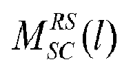
whereinν is an index counting the current OFDM symbol as hypothesis for the frame start,pR is an index counting the current receive antenna,NR is a number of receive antennas,L is a number of PUSCH layers,λ is an index counting the current PUSCH layer or PUCCH transmit antenna,MRS SC (l) is a length of the DMRS sequence of OFDM symbol l,l is an index counting the current DMRS OFDM symbol under the hypothesis that ν is the frame start ,k is an index counting the current subcarrier,k0 is a first allocated subcarrier,Δk is a correlation distance in subcarriers,rl,k(pR) is a received signal in the frequency domain,KPUCCH is a union of PUCCH subcarriers of all PUCCH transmit antennas of the considered OFDM symbol l,CpR, l, nS, λ (k) is a correlation metric, anddpR, PUCCH is a PUCCH metric. - Measuring device according to claim 2,
characterized in that
the frame start determination means (26) are setup for calculating the frame start metric furthermore using the following formulas:
and
and
and
whereinHpR,l,ns,λ (k) are estimated channel coefficients,nS is an index counting the current slot between 0 and 19,LPUCCH is a number of PUCCH transmit antennas,NPUCCH_DMRS is a number of PUCCH DMRS symbols in a slot,wλ(nS) is a scalar independent of the subcarrier k but dependent on the slot nS and layer λ, in case of PUSCH,wλ(ns) is called Orthogonal Cover Code (OCC),ru,ν α(λ,nS) is an ideal generated DMRS sequence dependent on the slot nS and layer λ,* is the complex conjugate operation,cpR,l,nS,λ(k) is a correlation metric,d1 pR,PUCCH is a metric for PUCCH in case of exactly one PUCCH transmit antenna or if each receive antenna contains the signal from one and only one transmit antenna,d2 pR,PUCCH is a metric for PUCCH for the general case. - Measuring device according to claim 3,
characterized in that
the frame start determination means (26) are setup for calculating the frame start metric furthermore using the following formulas:
and
whereinNPUSCH(ν) are PUSCH DMRS OFDM symbol positions under the hypothesis that ν is the frame start,NPUCCH(ν) are PUCCH DMRS OFDM symbol positions under the hypothesis that ν is the frame start,NSymbolsPerSlot is a number of symbols per slot,IPUSCH_DMRS_Pos is 3 for normal cyclic prefix and 2 for extended cyclic prefix, andX are PUCCH DMRS OFDM symbols positions in a slot which depends on the PUCCH format. - Measuring device according to any of the claims 1 to 4,
characterized in that
the frame start determination means (26) are set up for determining the frame start time by:determining a maximum of the frame start metric according to the following formula:
- Measuring device according to any of the claims 1 to 4,
characterized in that
the frame start determination means (26) are set up for determining the frame start time by:- determining candidates for the frame start time, according to the following formula: - evaluating the determined maxima regarding a most likely frame start time, by comparing the candidates with a given threshold, whereinmNUM(pr,ν) is a numerator of the overall frame start metric,pR is an index counting the current receive antenna, andν is an index counting the current OFDM symbol as hypothesis for the frame start.
 - Measuring device according to any of the claims 1 to 5,
characterized in that
the frame start determination means (26) are set up for calculating and evaluating the frame start metric only for a single PUSCH layer, even if only PUSCH layers that are not used for the frame start metric are contained in the received signal and even if more than one PUSCH layer is in use. - Measuring device according to any of the claims 1 to 7,
characterized in that
the processing means (13) comprise active resource block determination means (25) for determining active resource blocks of a first signal (37) derived from the digital measuring signal (33) by- determining a power of each received resource block, and- determining a resource block as active, if the determined power is above a given threshold, and the frame start determination means (26) are setup for determining the frame start time based upon the determined active resource blocks. - Measuring device according to claim 8,
characterized in that
the processing means (13) further comprise integer carrier frequency offset means (22) for determining an integer carrier frequency offset of the frequency domain measuring signal (35) by- determining a power Pl,k per subcarrier k of each OFDM symbol l,- determining a number of hypothesis for the integer carrier frequency offset depending on the number of OFDM symbols per slot,-summing up for each hypothesis iHyp the powers of its OFDM symbols according to - calculating the integer CFO metric for each hypothesis iHyp according to
with x being any postive number,- determining the integer carrier frequency offset for each hypothesis iHyp as the position where the integer CFO metric has its maximum according to - calculating for each hypothesis iHyp the difference Δd of the peak integer CFO metric value to a smaller metric value,- summing up the differences Δd for each integer carrier frequency offset, -determining the integer carrier frequency offset as the one with the highest sum of differences.
 - Measuring device according to claim 8 or 9,
characterized in that
the processing means (13) further comprise I/Q offset means (24) for determining and compensating an I/Q offset before determining the active resource blocks using the following formula:
whereinbeff(l,pR) is the I/Q offset,K is a set of subcarriers used for determining I/Q offset, Ck' is an interference function given by the following formula:
whereinn is an index counting the time domain samples,NFFT is an FFT window length, andΔn is a number of samples in the time domain depending on the start of the FFT window. - Method for measuring a frame start time in a measuring signal (30) comprising:- receiving the measuring signal (30) as a digital measuring signal (33), and- determining the frame start time,characterized by
determining the frame start time by calculating a frame start metric. - Method according to claim 11,
characterized in that
the frame start metric is calculated using the following formula:
wherein
and
and
whereinν is an index counting the current OFDM symbol as hypothesis for the frame start,pR is an index counting the current receive antenna,NR is a number of receive antennas,L is a number of PUSCH layers,λ is an index counting the current PUSCH layer or PUCCH transmit antenna,MRS SC (l) is a length of the DMRS sequence of OFDM symbol l,l is an index counting the current DMRS OFDM symbol under the hypothesis that ν is the frame start,k is an index counting the current subcarrier,k0 is a first allocated subcarrier,Δk is a correlation distance in subcarriers,rl,k(pR) is a received signal in the frequency domain,KPUCCH is a union of PUCCH subcarriers of all PUCCH transmit antennas of the considered OFDM symbol l,CpR, l, nS, λ (k) is a correlation metric, anddpR, PUCCH is a PUCCH metric. - Method according to claim 12,
characterized in that
the frame start metric is calculated furthermore using the following formulas:
and
and
and
whereinHpR,l,nS,λ (k) are estimated channel coefficients,nS is an index counting the current slot between 0 and 19,LPUCCH is a number of PUCCH transmit antennas,NPUCCH_DMRS is a number of PUCCH DMRS symbols in a slot,wλ(ns) is a scalar independent of the subcarrier k but dependent on the slot nS and layer λ, in case of PUSCH,wλ(ns) is called Orthogonal Cover Code (OCC),ru,ν α(λ,nS) is an ideal generated DMRS sequence dependent on the slot nS and layer λ,cpR,l,nS,λ(k) is a correlation metric,* is the complex conjugate operation,d1 pR,PUCCH is a metric for PUCCH in case of exactly one PUCCH transmit antenna or if each receive antenna contains the signal from one and only one transmit antenna, d2 pR,PUCCH is a metric for PUCCH for the general case. - Method according to claim 13,
characterized in that
the frame start metric is calculated furthermore using the following formula:
and
whereinNPUSCH(ν) are PUSCH DMRS OFDM symbol positions under the hypothesis that ν is the frame start,NPUCCH(ν) are PUCCH DMRS OFDM symbol positions under the hypothesis that ν is the frame start,NSymbolsPerSlot is a number of symbols per slot,IPUSCH_DMRS_Pos is 3 for normal cyclic prefix and 2 for extended cyclic prefix, andX are PUCCH DMRS OFDM symbols positions in a slot which depends on the PUCCH format. - Method according to any of the claims 11 to 14,
characterized by
determining the frame start time by:determining a maximum of the frame start metric according to the following formula:
- Method according to any of the claims 11 to 15,
characterized by
determining the frame start time by:- determining candidates for the frame start time, according to the following formula: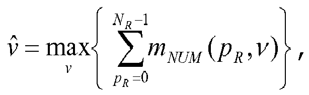 - evaluating the determined maxima regarding a most likely frame start time, by comparing the candidates with a given threshold, whereinmNUM(pr,ν) is a numerator of the overall frame start metric,pR is an index counting the current receive antenna, andν is an index counting the current OFDM symbol as hypothesis for the frame start.
 - Measuring device according to any of the claims 11 to 16,
characterized in that
the frame start metric is calculated and evaluated only for a single PUSCH layer, even if only PUSCH layers that are not used for the frame start metric are contained in the received signal and even if more than one PUSCH layer is in use. - Method according to any of the claims 11 to 17,
characterized by
determining active resource blocks of a first signal (37) derived from the digital measuring signal (33) by:- determining a power of each received resource block, and- determining a resource block as active, if the determined power is above a given threshold, and- determining the frame start time based upon the determined active resource blocks. - Method according to claim 18,
characterized by
determining an integer carrier frequency offset of the frequency domain measuring signal (35) by:- determining a power Pl,k per subcarrier k of each OFDM symbol l,- determining a number of hypothesis for the integer carrier frequency offset depending on the number of OFDM symbols per slot,- summing up for each hypothesis iHyp the powers of its OFDM symbols according to - calculating the integer CFO metric for each hypothesis iHyp according to
with x being any postive number,- determining the integer carrier frequency offset for each hypothesis iHyp as the position where the integer CFO metric has its maximum according to - calculating for each hypothesis iHyp the difference Δd of the peak integer CFO metric value to a smaller metric value,- summing up the differences Δd for each integer carrier frequency offset,- determining the integer carrier frequency offset as the one with the highest sum of differences.
 - Method according to claim 18 or 19,
characterized by
determining and compensating an I/Q offset before determining the active resource blocks using the following formula:
whereinbeff(l,pR) is the I/Q offset,K is a set of subcarriers used for determining I/Q offset,Ck' is an interference function given by the following formula:
whereinn is an index counting the time domain samples,NFFT is an FFT window length, andΔn is a number of samples in the time domain depending on the start of the FFT window. - A computer program with program code means for performing all steps according to any of the claims 11 to 20 if the program is executed on a computer or a digital signal processor.
- A computer program product having a computer readable medium with stored program code means for performing all steps according to any of the claims 11 to 20 if the program is executed on a computer or a digital signal processor.
Priority Applications (2)
| Application Number | Priority Date | Filing Date | Title |
|---|---|---|---|
| EP18189848.7A EP3422654B8 (en) | 2013-03-04 | 2014-01-16 | Measuring device and method for frame start detection |
| EP14151467.9A EP2775682B8 (en) | 2013-03-04 | 2014-01-16 | Measuring device and method for frame start detection |
Applications Claiming Priority (3)
| Application Number | Priority Date | Filing Date | Title |
|---|---|---|---|
| EP13157557 | 2013-03-04 | ||
| EP13175338 | 2013-07-05 | ||
| EP14151467.9A EP2775682B8 (en) | 2013-03-04 | 2014-01-16 | Measuring device and method for frame start detection |
Related Child Applications (2)
| Application Number | Title | Priority Date | Filing Date |
|---|---|---|---|
| EP18189848.7A Division EP3422654B8 (en) | 2013-03-04 | 2014-01-16 | Measuring device and method for frame start detection |
| EP18189848.7A Division-Into EP3422654B8 (en) | 2013-03-04 | 2014-01-16 | Measuring device and method for frame start detection |
Publications (4)
| Publication Number | Publication Date |
|---|---|
| EP2775682A2 true EP2775682A2 (en) | 2014-09-10 |
| EP2775682A3 EP2775682A3 (en) | 2017-11-15 |
| EP2775682B1 EP2775682B1 (en) | 2019-06-19 |
| EP2775682B8 EP2775682B8 (en) | 2019-07-24 |
Family
ID=49920298
Family Applications (2)
| Application Number | Title | Priority Date | Filing Date |
|---|---|---|---|
| EP18189848.7A Active EP3422654B8 (en) | 2013-03-04 | 2014-01-16 | Measuring device and method for frame start detection |
| EP14151467.9A Active EP2775682B8 (en) | 2013-03-04 | 2014-01-16 | Measuring device and method for frame start detection |
Family Applications Before (1)
| Application Number | Title | Priority Date | Filing Date |
|---|---|---|---|
| EP18189848.7A Active EP3422654B8 (en) | 2013-03-04 | 2014-01-16 | Measuring device and method for frame start detection |
Country Status (1)
| Country | Link |
|---|---|
| EP (2) | EP3422654B8 (en) |
Cited By (4)
| Publication number | Priority date | Publication date | Assignee | Title |
|---|---|---|---|---|
| CN114257481A (en) * | 2020-09-24 | 2022-03-29 | 大唐联仪科技有限公司 | Time slot synchronization detection method, equipment, device and storage medium |
| US20220247537A1 (en) * | 2019-07-12 | 2022-08-04 | Telefonaktiebolaget Lm Ericsson (Publ) | Method for selecting physical uplink control channel (pucch) orthogonal cover codes (occ) repetition sequence |
| CN115842704A (en) * | 2021-09-18 | 2023-03-24 | 大唐联仪科技有限公司 | Uplink signal subframe synchronization method, device, apparatus and storage medium |
| US20230283746A1 (en) * | 2022-03-04 | 2023-09-07 | Realtek Semiconductor Corp. | Receiver device and signal processing method |
Citations (1)
| Publication number | Priority date | Publication date | Assignee | Title |
|---|---|---|---|---|
| EP1583267B1 (en) | 2003-01-10 | 2008-03-12 | Diseno de Sistemas en Silicio S.A. | Method for the time- and frequency-domain synchronisation of multiple devices in a transmission system with ofdm modulation |
Family Cites Families (3)
| Publication number | Priority date | Publication date | Assignee | Title |
|---|---|---|---|---|
| GB0803333D0 (en) * | 2008-02-23 | 2008-04-02 | Univ Surrey | Frame timing and carrier frequency recovery for frequency selective signals |
| CN101741800B (en) * | 2009-10-14 | 2014-07-09 | 苏州恩巨网络有限公司 | Synchronous searching method |
| DE102011008731B4 (en) * | 2011-01-17 | 2016-10-06 | Rohde & Schwarz Gmbh & Co. Kg | Method and device for determining the start of a data frame in an OFDM data stream |
-
2014
- 2014-01-16 EP EP18189848.7A patent/EP3422654B8/en active Active
- 2014-01-16 EP EP14151467.9A patent/EP2775682B8/en active Active
Patent Citations (1)
| Publication number | Priority date | Publication date | Assignee | Title |
|---|---|---|---|---|
| EP1583267B1 (en) | 2003-01-10 | 2008-03-12 | Diseno de Sistemas en Silicio S.A. | Method for the time- and frequency-domain synchronisation of multiple devices in a transmission system with ofdm modulation |
Cited By (6)
| Publication number | Priority date | Publication date | Assignee | Title |
|---|---|---|---|---|
| US20220247537A1 (en) * | 2019-07-12 | 2022-08-04 | Telefonaktiebolaget Lm Ericsson (Publ) | Method for selecting physical uplink control channel (pucch) orthogonal cover codes (occ) repetition sequence |
| CN114257481A (en) * | 2020-09-24 | 2022-03-29 | 大唐联仪科技有限公司 | Time slot synchronization detection method, equipment, device and storage medium |
| CN114257481B (en) * | 2020-09-24 | 2024-03-08 | 大唐联仪科技有限公司 | Time slot synchronization detection method, device, apparatus and storage medium |
| CN115842704A (en) * | 2021-09-18 | 2023-03-24 | 大唐联仪科技有限公司 | Uplink signal subframe synchronization method, device, apparatus and storage medium |
| US20230283746A1 (en) * | 2022-03-04 | 2023-09-07 | Realtek Semiconductor Corp. | Receiver device and signal processing method |
| US12022232B2 (en) * | 2022-03-04 | 2024-06-25 | Realtek Semiconductor Corp. | Receiver device and signal processing method |
Also Published As
| Publication number | Publication date |
|---|---|
| EP3422654B8 (en) | 2021-08-18 |
| EP2775682B8 (en) | 2019-07-24 |
| EP3422654A2 (en) | 2019-01-02 |
| EP2775682A3 (en) | 2017-11-15 |
| EP3422654A3 (en) | 2019-04-03 |
| EP3422654B1 (en) | 2021-07-14 |
| EP2775682B1 (en) | 2019-06-19 |
Similar Documents
| Publication | Publication Date | Title |
|---|---|---|
| EP3086492B1 (en) | Lte frame synchronization detection method and apparatus and relay apparatus applying same | |
| US10219238B2 (en) | OTDOA in LTE networks | |
| US8446894B2 (en) | Systems and methods for performing initial synchronization in wireless communications systems | |
| US9807718B2 (en) | Secondary cell synchronization for carrier aggregation | |
| US7336647B2 (en) | System and method for ranging | |
| US20080198942A1 (en) | Long echo detection and channel estimation for ofdm systems | |
| US8718159B2 (en) | Receiver with cyclic prefix determination | |
| US8599828B2 (en) | Non-coherent secondary synchronization signal detecting method, device and corresponding computer program | |
| US20060039451A1 (en) | Method and apparatus for fast cell search | |
| KR101808189B1 (en) | Apparatus and method for estimating doppler spread in mobile communication system | |
| AU2017219686B2 (en) | NB-loT receiver operating at minimum sampling rate | |
| EP2775682B1 (en) | Measuring device and method for frame start detection | |
| JP5368457B2 (en) | Communication device and method | |
| CN117320046B (en) | CRS searching method, LTE time alignment error measuring method and user equipment | |
| US20110142142A1 (en) | Apparatus and method for estimating channel in channel domain | |
| US8891706B2 (en) | System and method for optimizing use of channel state information | |
| CN101741800A (en) | Synchronous searching method | |
| EP2941852A1 (en) | Method for estimating and removing dc offset | |
| KR101346436B1 (en) | Apparatus and method of estimating channel using adaptive channel estimation window in wireless communication based on CAZAC sequence | |
| EP2595352B1 (en) | Method and apparatus for enhanced channel estimation using a frame based compensation of changes of the communication channel | |
| KR101005126B1 (en) | Residual Frequency Offset Estimation Method and Apparatus for Orthogonal Frequency Division Multiplexing Receiver | |
| KR20230090121A (en) | Apparatus and method for estimating symbol timing offset for 5g communication system | |
| KR101071050B1 (en) | P-sch detection method and receiver thererfor | |
| KR20170091030A (en) | Digital audio broadcasting system based on ofdm and method of mode and frame detection using the same | |
| Choi et al. | An adaptive cell search and integral frequency offset estimation in mobile WiMAX |
Legal Events
| Date | Code | Title | Description |
|---|---|---|---|
| PUAI | Public reference made under article 153(3) epc to a published international application that has entered the european phase |
Free format text: ORIGINAL CODE: 0009012 |
|
| 17P | Request for examination filed |
Effective date: 20140116 |
|
| AK | Designated contracting states |
Kind code of ref document: A2 Designated state(s): AL AT BE BG CH CY CZ DE DK EE ES FI FR GB GR HR HU IE IS IT LI LT LU LV MC MK MT NL NO PL PT RO RS SE SI SK SM TR |
|
| AX | Request for extension of the european patent |
Extension state: BA ME |
|
| RIC1 | Information provided on ipc code assigned before grant |
Ipc: H04L 27/38 20060101ALN20170704BHEP Ipc: H04L 27/26 20060101AFI20170704BHEP |
|
| PUAL | Search report despatched |
Free format text: ORIGINAL CODE: 0009013 |
|
| AK | Designated contracting states |
Kind code of ref document: A3 Designated state(s): AL AT BE BG CH CY CZ DE DK EE ES FI FR GB GR HR HU IE IS IT LI LT LU LV MC MK MT NL NO PL PT RO RS SE SI SK SM TR |
|
| AX | Request for extension of the european patent |
Extension state: BA ME |
|
| RIC1 | Information provided on ipc code assigned before grant |
Ipc: H04L 27/38 20060101ALN20171012BHEP Ipc: H04L 27/26 20060101AFI20171012BHEP |
|
| STAA | Information on the status of an ep patent application or granted ep patent |
Free format text: STATUS: REQUEST FOR EXAMINATION WAS MADE |
|
| R17P | Request for examination filed (corrected) |
Effective date: 20180316 |
|
| RBV | Designated contracting states (corrected) |
Designated state(s): AL AT BE BG CH CY CZ DE DK EE ES FI FR GB GR HR HU IE IS IT LI LT LU LV MC MK MT NL NO PL PT RO RS SE SI SK SM TR |
|
| GRAP | Despatch of communication of intention to grant a patent |
Free format text: ORIGINAL CODE: EPIDOSNIGR1 |
|
| STAA | Information on the status of an ep patent application or granted ep patent |
Free format text: STATUS: GRANT OF PATENT IS INTENDED |
|
| INTG | Intention to grant announced |
Effective date: 20190125 |
|
| RIC1 | Information provided on ipc code assigned before grant |
Ipc: H04L 27/26 20060101AFI20190115BHEP Ipc: H04L 27/38 20060101ALN20190115BHEP |
|
| GRAS | Grant fee paid |
Free format text: ORIGINAL CODE: EPIDOSNIGR3 |
|
| GRAA | (expected) grant |
Free format text: ORIGINAL CODE: 0009210 |
|
| STAA | Information on the status of an ep patent application or granted ep patent |
Free format text: STATUS: THE PATENT HAS BEEN GRANTED |
|
| AK | Designated contracting states |
Kind code of ref document: B1 Designated state(s): AL AT BE BG CH CY CZ DE DK EE ES FI FR GB GR HR HU IE IS IT LI LT LU LV MC MK MT NL NO PL PT RO RS SE SI SK SM TR |
|
| REG | Reference to a national code |
Ref country code: GB Ref legal event code: FG4D |
|
| REG | Reference to a national code |
Ref country code: CH Ref legal event code: PK Free format text: DIE BENENNUNG CH/LI WURDE VOR DER ERTEILUNG ZURUECKGENOMMEN. Ref country code: CH Ref legal event code: EP |
|
| RBV | Designated contracting states (corrected) |
Designated state(s): AL AT BE BG CH CY CZ DE DK EE ES FI FR GB GR HR HU IE IS IT LI LT LU LV MC MK MT NL NO PL PT RO RS SE SI SK SM TR |
|
| RBV | Designated contracting states (corrected) |
Designated state(s): AL AT BE BG CY CZ DE DK EE ES FI FR GB GR HR HU IS IT LT LU LV MC MK MT NL NO PL PT RO RS SE SI SK SM TR |
|
| REG | Reference to a national code |
Ref country code: IE Ref legal event code: FG4D |
|
| REG | Reference to a national code |
Ref country code: DE Ref legal event code: R096 Ref document number: 602014048487 Country of ref document: DE |
|
| REG | Reference to a national code |
Ref country code: AT Ref legal event code: REF Ref document number: 1146935 Country of ref document: AT Kind code of ref document: T Effective date: 20190715 |
|
| REG | Reference to a national code |
Ref country code: NL Ref legal event code: MP Effective date: 20190619 |
|
| PG25 | Lapsed in a contracting state [announced via postgrant information from national office to epo] |
Ref country code: NO Free format text: LAPSE BECAUSE OF FAILURE TO SUBMIT A TRANSLATION OF THE DESCRIPTION OR TO PAY THE FEE WITHIN THE PRESCRIBED TIME-LIMIT Effective date: 20190919 Ref country code: FI Free format text: LAPSE BECAUSE OF FAILURE TO SUBMIT A TRANSLATION OF THE DESCRIPTION OR TO PAY THE FEE WITHIN THE PRESCRIBED TIME-LIMIT Effective date: 20190619 Ref country code: HR Free format text: LAPSE BECAUSE OF FAILURE TO SUBMIT A TRANSLATION OF THE DESCRIPTION OR TO PAY THE FEE WITHIN THE PRESCRIBED TIME-LIMIT Effective date: 20190619 Ref country code: LT Free format text: LAPSE BECAUSE OF FAILURE TO SUBMIT A TRANSLATION OF THE DESCRIPTION OR TO PAY THE FEE WITHIN THE PRESCRIBED TIME-LIMIT Effective date: 20190619 Ref country code: AL Free format text: LAPSE BECAUSE OF FAILURE TO SUBMIT A TRANSLATION OF THE DESCRIPTION OR TO PAY THE FEE WITHIN THE PRESCRIBED TIME-LIMIT Effective date: 20190619 Ref country code: SE Free format text: LAPSE BECAUSE OF FAILURE TO SUBMIT A TRANSLATION OF THE DESCRIPTION OR TO PAY THE FEE WITHIN THE PRESCRIBED TIME-LIMIT Effective date: 20190619 |
|
| REG | Reference to a national code |
Ref country code: LT Ref legal event code: MG4D |
|
| PG25 | Lapsed in a contracting state [announced via postgrant information from national office to epo] |
Ref country code: GR Free format text: LAPSE BECAUSE OF FAILURE TO SUBMIT A TRANSLATION OF THE DESCRIPTION OR TO PAY THE FEE WITHIN THE PRESCRIBED TIME-LIMIT Effective date: 20190920 Ref country code: RS Free format text: LAPSE BECAUSE OF FAILURE TO SUBMIT A TRANSLATION OF THE DESCRIPTION OR TO PAY THE FEE WITHIN THE PRESCRIBED TIME-LIMIT Effective date: 20190619 Ref country code: LV Free format text: LAPSE BECAUSE OF FAILURE TO SUBMIT A TRANSLATION OF THE DESCRIPTION OR TO PAY THE FEE WITHIN THE PRESCRIBED TIME-LIMIT Effective date: 20190619 Ref country code: BG Free format text: LAPSE BECAUSE OF FAILURE TO SUBMIT A TRANSLATION OF THE DESCRIPTION OR TO PAY THE FEE WITHIN THE PRESCRIBED TIME-LIMIT Effective date: 20190919 |
|
| REG | Reference to a national code |
Ref country code: AT Ref legal event code: MK05 Ref document number: 1146935 Country of ref document: AT Kind code of ref document: T Effective date: 20190619 |
|
| PG25 | Lapsed in a contracting state [announced via postgrant information from national office to epo] |
Ref country code: RO Free format text: LAPSE BECAUSE OF FAILURE TO SUBMIT A TRANSLATION OF THE DESCRIPTION OR TO PAY THE FEE WITHIN THE PRESCRIBED TIME-LIMIT Effective date: 20190619 Ref country code: CZ Free format text: LAPSE BECAUSE OF FAILURE TO SUBMIT A TRANSLATION OF THE DESCRIPTION OR TO PAY THE FEE WITHIN THE PRESCRIBED TIME-LIMIT Effective date: 20190619 Ref country code: SK Free format text: LAPSE BECAUSE OF FAILURE TO SUBMIT A TRANSLATION OF THE DESCRIPTION OR TO PAY THE FEE WITHIN THE PRESCRIBED TIME-LIMIT Effective date: 20190619 Ref country code: PT Free format text: LAPSE BECAUSE OF FAILURE TO SUBMIT A TRANSLATION OF THE DESCRIPTION OR TO PAY THE FEE WITHIN THE PRESCRIBED TIME-LIMIT Effective date: 20191021 Ref country code: EE Free format text: LAPSE BECAUSE OF FAILURE TO SUBMIT A TRANSLATION OF THE DESCRIPTION OR TO PAY THE FEE WITHIN THE PRESCRIBED TIME-LIMIT Effective date: 20190619 Ref country code: NL Free format text: LAPSE BECAUSE OF FAILURE TO SUBMIT A TRANSLATION OF THE DESCRIPTION OR TO PAY THE FEE WITHIN THE PRESCRIBED TIME-LIMIT Effective date: 20190619 Ref country code: AT Free format text: LAPSE BECAUSE OF FAILURE TO SUBMIT A TRANSLATION OF THE DESCRIPTION OR TO PAY THE FEE WITHIN THE PRESCRIBED TIME-LIMIT Effective date: 20190619 |
|
| PG25 | Lapsed in a contracting state [announced via postgrant information from national office to epo] |
Ref country code: IT Free format text: LAPSE BECAUSE OF FAILURE TO SUBMIT A TRANSLATION OF THE DESCRIPTION OR TO PAY THE FEE WITHIN THE PRESCRIBED TIME-LIMIT Effective date: 20190619 Ref country code: IS Free format text: LAPSE BECAUSE OF FAILURE TO SUBMIT A TRANSLATION OF THE DESCRIPTION OR TO PAY THE FEE WITHIN THE PRESCRIBED TIME-LIMIT Effective date: 20191019 Ref country code: SM Free format text: LAPSE BECAUSE OF FAILURE TO SUBMIT A TRANSLATION OF THE DESCRIPTION OR TO PAY THE FEE WITHIN THE PRESCRIBED TIME-LIMIT Effective date: 20190619 Ref country code: ES Free format text: LAPSE BECAUSE OF FAILURE TO SUBMIT A TRANSLATION OF THE DESCRIPTION OR TO PAY THE FEE WITHIN THE PRESCRIBED TIME-LIMIT Effective date: 20190619 |
|
| PG25 | Lapsed in a contracting state [announced via postgrant information from national office to epo] |
Ref country code: TR Free format text: LAPSE BECAUSE OF FAILURE TO SUBMIT A TRANSLATION OF THE DESCRIPTION OR TO PAY THE FEE WITHIN THE PRESCRIBED TIME-LIMIT Effective date: 20190619 |
|
| PG25 | Lapsed in a contracting state [announced via postgrant information from national office to epo] |
Ref country code: DK Free format text: LAPSE BECAUSE OF FAILURE TO SUBMIT A TRANSLATION OF THE DESCRIPTION OR TO PAY THE FEE WITHIN THE PRESCRIBED TIME-LIMIT Effective date: 20190619 Ref country code: PL Free format text: LAPSE BECAUSE OF FAILURE TO SUBMIT A TRANSLATION OF THE DESCRIPTION OR TO PAY THE FEE WITHIN THE PRESCRIBED TIME-LIMIT Effective date: 20190619 |
|
| PGFP | Annual fee paid to national office [announced via postgrant information from national office to epo] |
Ref country code: DE Payment date: 20200130 Year of fee payment: 7 |
|
| PG25 | Lapsed in a contracting state [announced via postgrant information from national office to epo] |
Ref country code: IS Free format text: LAPSE BECAUSE OF FAILURE TO SUBMIT A TRANSLATION OF THE DESCRIPTION OR TO PAY THE FEE WITHIN THE PRESCRIBED TIME-LIMIT Effective date: 20200224 |
|
| REG | Reference to a national code |
Ref country code: DE Ref legal event code: R097 Ref document number: 602014048487 Country of ref document: DE |
|
| PLBE | No opposition filed within time limit |
Free format text: ORIGINAL CODE: 0009261 |
|
| STAA | Information on the status of an ep patent application or granted ep patent |
Free format text: STATUS: NO OPPOSITION FILED WITHIN TIME LIMIT |
|
| PG2D | Information on lapse in contracting state deleted |
Ref country code: IS |
|
| 26N | No opposition filed |
Effective date: 20200603 |
|
| PG25 | Lapsed in a contracting state [announced via postgrant information from national office to epo] |
Ref country code: SI Free format text: LAPSE BECAUSE OF FAILURE TO SUBMIT A TRANSLATION OF THE DESCRIPTION OR TO PAY THE FEE WITHIN THE PRESCRIBED TIME-LIMIT Effective date: 20190619 Ref country code: MC Free format text: LAPSE BECAUSE OF FAILURE TO SUBMIT A TRANSLATION OF THE DESCRIPTION OR TO PAY THE FEE WITHIN THE PRESCRIBED TIME-LIMIT Effective date: 20190619 |
|
| GBPC | Gb: european patent ceased through non-payment of renewal fee |
Effective date: 20200116 |
|
| REG | Reference to a national code |
Ref country code: BE Ref legal event code: MM Effective date: 20200131 |
|
| PG25 | Lapsed in a contracting state [announced via postgrant information from national office to epo] |
Ref country code: GB Free format text: LAPSE BECAUSE OF NON-PAYMENT OF DUE FEES Effective date: 20200116 Ref country code: LU Free format text: LAPSE BECAUSE OF NON-PAYMENT OF DUE FEES Effective date: 20200116 Ref country code: FR Free format text: LAPSE BECAUSE OF NON-PAYMENT OF DUE FEES Effective date: 20200131 |
|
| PG25 | Lapsed in a contracting state [announced via postgrant information from national office to epo] |
Ref country code: BE Free format text: LAPSE BECAUSE OF NON-PAYMENT OF DUE FEES Effective date: 20200131 |
|
| REG | Reference to a national code |
Ref country code: DE Ref legal event code: R119 Ref document number: 602014048487 Country of ref document: DE |
|
| PG25 | Lapsed in a contracting state [announced via postgrant information from national office to epo] |
Ref country code: DE Free format text: LAPSE BECAUSE OF NON-PAYMENT OF DUE FEES Effective date: 20210803 |
|
| PG25 | Lapsed in a contracting state [announced via postgrant information from national office to epo] |
Ref country code: MT Free format text: LAPSE BECAUSE OF FAILURE TO SUBMIT A TRANSLATION OF THE DESCRIPTION OR TO PAY THE FEE WITHIN THE PRESCRIBED TIME-LIMIT Effective date: 20190619 Ref country code: CY Free format text: LAPSE BECAUSE OF FAILURE TO SUBMIT A TRANSLATION OF THE DESCRIPTION OR TO PAY THE FEE WITHIN THE PRESCRIBED TIME-LIMIT Effective date: 20190619 |
|
| PG25 | Lapsed in a contracting state [announced via postgrant information from national office to epo] |
Ref country code: MK Free format text: LAPSE BECAUSE OF FAILURE TO SUBMIT A TRANSLATION OF THE DESCRIPTION OR TO PAY THE FEE WITHIN THE PRESCRIBED TIME-LIMIT Effective date: 20190619 |