EP2775607A2 - Motor control unit - Google Patents
Motor control unit Download PDFInfo
- Publication number
- EP2775607A2 EP2775607A2 EP14158033.2A EP14158033A EP2775607A2 EP 2775607 A2 EP2775607 A2 EP 2775607A2 EP 14158033 A EP14158033 A EP 14158033A EP 2775607 A2 EP2775607 A2 EP 2775607A2
- Authority
- EP
- European Patent Office
- Prior art keywords
- motor
- angular velocity
- capacitor
- power supply
- control unit
- Prior art date
- Legal status (The legal status is an assumption and is not a legal conclusion. Google has not performed a legal analysis and makes no representation as to the accuracy of the status listed.)
- Granted
Links
- 239000003990 capacitor Substances 0.000 claims abstract description 46
- 230000005540 biological transmission Effects 0.000 claims abstract description 16
- 238000006243 chemical reaction Methods 0.000 description 6
- 238000010438 heat treatment Methods 0.000 description 6
- 238000000034 method Methods 0.000 description 6
- 230000002093 peripheral effect Effects 0.000 description 5
- 238000010586 diagram Methods 0.000 description 3
- 238000013507 mapping Methods 0.000 description 2
- 238000007599 discharging Methods 0.000 description 1
- 230000000694 effects Effects 0.000 description 1
- 230000005669 field effect Effects 0.000 description 1
Images


Classifications
-
- B—PERFORMING OPERATIONS; TRANSPORTING
- B60—VEHICLES IN GENERAL
- B60L—PROPULSION OF ELECTRICALLY-PROPELLED VEHICLES; SUPPLYING ELECTRIC POWER FOR AUXILIARY EQUIPMENT OF ELECTRICALLY-PROPELLED VEHICLES; ELECTRODYNAMIC BRAKE SYSTEMS FOR VEHICLES IN GENERAL; MAGNETIC SUSPENSION OR LEVITATION FOR VEHICLES; MONITORING OPERATING VARIABLES OF ELECTRICALLY-PROPELLED VEHICLES; ELECTRIC SAFETY DEVICES FOR ELECTRICALLY-PROPELLED VEHICLES
- B60L15/00—Methods, circuits, or devices for controlling the traction-motor speed of electrically-propelled vehicles
- B60L15/20—Methods, circuits, or devices for controlling the traction-motor speed of electrically-propelled vehicles for control of the vehicle or its driving motor to achieve a desired performance, e.g. speed, torque, programmed variation of speed
- B60L15/2054—Methods, circuits, or devices for controlling the traction-motor speed of electrically-propelled vehicles for control of the vehicle or its driving motor to achieve a desired performance, e.g. speed, torque, programmed variation of speed by controlling transmissions or clutches
-
- B—PERFORMING OPERATIONS; TRANSPORTING
- B60—VEHICLES IN GENERAL
- B60L—PROPULSION OF ELECTRICALLY-PROPELLED VEHICLES; SUPPLYING ELECTRIC POWER FOR AUXILIARY EQUIPMENT OF ELECTRICALLY-PROPELLED VEHICLES; ELECTRODYNAMIC BRAKE SYSTEMS FOR VEHICLES IN GENERAL; MAGNETIC SUSPENSION OR LEVITATION FOR VEHICLES; MONITORING OPERATING VARIABLES OF ELECTRICALLY-PROPELLED VEHICLES; ELECTRIC SAFETY DEVICES FOR ELECTRICALLY-PROPELLED VEHICLES
- B60L3/00—Electric devices on electrically-propelled vehicles for safety purposes; Monitoring operating variables, e.g. speed, deceleration or energy consumption
- B60L3/0023—Detecting, eliminating, remedying or compensating for drive train abnormalities, e.g. failures within the drive train
- B60L3/0046—Detecting, eliminating, remedying or compensating for drive train abnormalities, e.g. failures within the drive train relating to electric energy storage systems, e.g. batteries or capacitors
-
- B—PERFORMING OPERATIONS; TRANSPORTING
- B60—VEHICLES IN GENERAL
- B60L—PROPULSION OF ELECTRICALLY-PROPELLED VEHICLES; SUPPLYING ELECTRIC POWER FOR AUXILIARY EQUIPMENT OF ELECTRICALLY-PROPELLED VEHICLES; ELECTRODYNAMIC BRAKE SYSTEMS FOR VEHICLES IN GENERAL; MAGNETIC SUSPENSION OR LEVITATION FOR VEHICLES; MONITORING OPERATING VARIABLES OF ELECTRICALLY-PROPELLED VEHICLES; ELECTRIC SAFETY DEVICES FOR ELECTRICALLY-PROPELLED VEHICLES
- B60L50/00—Electric propulsion with power supplied within the vehicle
- B60L50/40—Electric propulsion with power supplied within the vehicle using propulsion power supplied by capacitors
-
- B—PERFORMING OPERATIONS; TRANSPORTING
- B60—VEHICLES IN GENERAL
- B60L—PROPULSION OF ELECTRICALLY-PROPELLED VEHICLES; SUPPLYING ELECTRIC POWER FOR AUXILIARY EQUIPMENT OF ELECTRICALLY-PROPELLED VEHICLES; ELECTRODYNAMIC BRAKE SYSTEMS FOR VEHICLES IN GENERAL; MAGNETIC SUSPENSION OR LEVITATION FOR VEHICLES; MONITORING OPERATING VARIABLES OF ELECTRICALLY-PROPELLED VEHICLES; ELECTRIC SAFETY DEVICES FOR ELECTRICALLY-PROPELLED VEHICLES
- B60L58/00—Methods or circuit arrangements for monitoring or controlling batteries or fuel cells, specially adapted for electric vehicles
- B60L58/10—Methods or circuit arrangements for monitoring or controlling batteries or fuel cells, specially adapted for electric vehicles for monitoring or controlling batteries
-
- H—ELECTRICITY
- H02—GENERATION; CONVERSION OR DISTRIBUTION OF ELECTRIC POWER
- H02P—CONTROL OR REGULATION OF ELECTRIC MOTORS, ELECTRIC GENERATORS OR DYNAMO-ELECTRIC CONVERTERS; CONTROLLING TRANSFORMERS, REACTORS OR CHOKE COILS
- H02P23/00—Arrangements or methods for the control of AC motors characterised by a control method other than vector control
- H02P23/16—Controlling the angular speed of one shaft
-
- H—ELECTRICITY
- H02—GENERATION; CONVERSION OR DISTRIBUTION OF ELECTRIC POWER
- H02P—CONTROL OR REGULATION OF ELECTRIC MOTORS, ELECTRIC GENERATORS OR DYNAMO-ELECTRIC CONVERTERS; CONTROLLING TRANSFORMERS, REACTORS OR CHOKE COILS
- H02P27/00—Arrangements or methods for the control of AC motors characterised by the kind of supply voltage
- H02P27/04—Arrangements or methods for the control of AC motors characterised by the kind of supply voltage using variable-frequency supply voltage, e.g. inverter or converter supply voltage
-
- H—ELECTRICITY
- H02—GENERATION; CONVERSION OR DISTRIBUTION OF ELECTRIC POWER
- H02P—CONTROL OR REGULATION OF ELECTRIC MOTORS, ELECTRIC GENERATORS OR DYNAMO-ELECTRIC CONVERTERS; CONTROLLING TRANSFORMERS, REACTORS OR CHOKE COILS
- H02P6/00—Arrangements for controlling synchronous motors or other dynamo-electric motors using electronic commutation dependent on the rotor position; Electronic commutators therefor
- H02P6/20—Arrangements for starting
-
- Y—GENERAL TAGGING OF NEW TECHNOLOGICAL DEVELOPMENTS; GENERAL TAGGING OF CROSS-SECTIONAL TECHNOLOGIES SPANNING OVER SEVERAL SECTIONS OF THE IPC; TECHNICAL SUBJECTS COVERED BY FORMER USPC CROSS-REFERENCE ART COLLECTIONS [XRACs] AND DIGESTS
- Y02—TECHNOLOGIES OR APPLICATIONS FOR MITIGATION OR ADAPTATION AGAINST CLIMATE CHANGE
- Y02T—CLIMATE CHANGE MITIGATION TECHNOLOGIES RELATED TO TRANSPORTATION
- Y02T10/00—Road transport of goods or passengers
- Y02T10/60—Other road transportation technologies with climate change mitigation effect
- Y02T10/64—Electric machine technologies in electromobility
-
- Y—GENERAL TAGGING OF NEW TECHNOLOGICAL DEVELOPMENTS; GENERAL TAGGING OF CROSS-SECTIONAL TECHNOLOGIES SPANNING OVER SEVERAL SECTIONS OF THE IPC; TECHNICAL SUBJECTS COVERED BY FORMER USPC CROSS-REFERENCE ART COLLECTIONS [XRACs] AND DIGESTS
- Y02—TECHNOLOGIES OR APPLICATIONS FOR MITIGATION OR ADAPTATION AGAINST CLIMATE CHANGE
- Y02T—CLIMATE CHANGE MITIGATION TECHNOLOGIES RELATED TO TRANSPORTATION
- Y02T10/00—Road transport of goods or passengers
- Y02T10/60—Other road transportation technologies with climate change mitigation effect
- Y02T10/70—Energy storage systems for electromobility, e.g. batteries
-
- Y—GENERAL TAGGING OF NEW TECHNOLOGICAL DEVELOPMENTS; GENERAL TAGGING OF CROSS-SECTIONAL TECHNOLOGIES SPANNING OVER SEVERAL SECTIONS OF THE IPC; TECHNICAL SUBJECTS COVERED BY FORMER USPC CROSS-REFERENCE ART COLLECTIONS [XRACs] AND DIGESTS
- Y02—TECHNOLOGIES OR APPLICATIONS FOR MITIGATION OR ADAPTATION AGAINST CLIMATE CHANGE
- Y02T—CLIMATE CHANGE MITIGATION TECHNOLOGIES RELATED TO TRANSPORTATION
- Y02T10/00—Road transport of goods or passengers
- Y02T10/60—Other road transportation technologies with climate change mitigation effect
- Y02T10/72—Electric energy management in electromobility
Definitions
- the invention relates to a motor control unit.
- a control unit for the motor is provided with a switch, such as a power supply relay, disposed at an intermediate portion of a power supply line (electric power supply path) that connects a driving circuit of the control unit and an external power supply to each other.
- a switch such as a power supply relay
- a capacitor used to, for example, smooth an electric current is disposed on an intermediate portion of the power supply line.
- JP 11-89264 A describes a motor control unit that carries out electric discharge from a capacitor by causing electric charges stored in the capacitor to flow to a motor after a switch is turned off to bring an power supply line out of conduction.
- JP 11-89264 A describes a method of carrying out electric discharge by supplying electric power based on the electric charges stored in the capacitor to the motor such that torque is generated, and a method of carrying out electric discharge by supplying electric power to the motor such that torque is not generated.
- the former method has an advantage that it is possible to carry out electric discharge while suppressing resistance heating, whereas the latter method has an advantage that it is possible to carry out electric discharge without rotating the motor.
- some vehicles such as electric vehicles and hybrid vehicles are provided with an interrupting mechanism, such as a clutch, which allows or interrupts torque transmission and which is disposed between a motor serving as a driving source and a wheel.
- an interrupting mechanism such as a clutch
- the interrupting mechanism is disposed between the motor and a driven body that forms a load as described above, by interrupting torque transmission between the motor and the driven body when carrying out electric discharge from a capacitor, it is possible to carry out electric discharge from the capacitor while suppressing resistance heating, according to the former method described in JP 11-89264 A , in which electric power is supplied to the motor such that torque is generated.
- One object of the invention is to provide a motor control unit that is able to carry out electric discharge from a capacitor while suppressing resistance heating and preventing an excessive burden from being placed on a motor and its peripheral components.
- An aspect of the invention relates to a motor control unit that controls an operation of a motor connected to a driven body via an interrupting mechanism that allows or interrupts torque transmission between the motor and the driven body.
- the motor control unit includes: a control circuit that outputs a motor control signal for controlling the operation of the motor; a driving circuit that supplies driving electric power to the motor based on the motor control signal; and a capacitor provided at an intermediate portion of a power supply line that connects the driving circuit and an external power supply to each other.
- the control circuit carries out electric discharge from the capacitor by supplying electric power generated by electric charges stored in the capacitor to the motor such that torque is generated by the motor, with torque transmission between the motor and the driven body interrupted by the interrupting mechanism, after a switch provided at an intermediate portion of the power supply line is turned off.
- the control circuit controls electric power supply to the motor such that an angular velocity of the motor becomes less than or equal to a prescribed angular velocity, at the time of the electric discharge from the capacitor.
- the electric power is supplied to the motor such that torque is generated by the motor, it is possible to carry out electric discharge from the capacitor while suppressing resistance heating.
- the angular velocity of the motor is controlled so as to become less than or equal to the prescribed angular velocity. Therefore, even if electric power is supplied to the motor with torque transmission between the motor and the driven body interrupted, that is, with no load placed on the motor, the motor is prevented from rotating an excessively high angular velocity. In this way, it is possible to prevent an excessive burden from being placed on the motor itself and its peripheral components.
- the motor control unit 1 illustrated in FIG. 1 is used to control the operation of a motor 2 used as a driving source for travelling of an electric vehicle, a hybrid vehicle, or the like.
- the motor 2 is connected to a wheel 4, which is an example of a driven body, via a clutch 3 that may function as an interrupting mechanism.
- a clutch 3 When the clutch 3 is engaged, the motor 2 and the wheel 4 are connected to each other to allow torque transmission.
- the clutch 3 is disengaged, the motor 2 and the wheel 4 are disconnected from each other to interrupt torque transmission.
- a brushless motor is adopted as the motor 2 in the present embodiment.
- the motor control unit 1 includes a microcomputer 11 that may function as a control circuit and that outputs a motor control signal S_m, and a driving circuit 12 that supplies driving electric power to the motor 2 on the basis of the motor control signal S_m output from the microcomputer 11.
- a known PWM inverter is adopted.
- a pair of switching elements for example, FETs
- the PWM inverter is formed by connecting multiples pairs of the switching elements in parallel such that the pairs of switching elements respectively correspond to a U-phase motor coil 5u, a V-phase motor coil 5v, and a W-phase motor coil 5w.
- the motor control signal S_m output from the microcomputer 11 is used to define the on-off state of each switching element.
- Each switching element is turned on or off in response to the motor control signal S_m and thus the energization patterns of the U-phase motor coil 5u, the V-phase motor coil 5v, and the W-phase motor coil 5w are switched. In this way, three-phase driving electric power is output to the motor 2.
- the microcomputer 11 is connected to a power supply (battery) 13 for control (hereinafter, referred to as "control power supply 13") through a power supply line Ls.
- a relay circuit 14 formed by connecting, in parallel, control relays 14a, 14b, each of which is a mechanical relay, is provided at an intermediate portion of the power supply line Ls.
- the driving circuit 12 is connected to a power supply (battery) 15 for driving (hereinafter, referred to as "driving power supply”), which may function as an external power supply, through a power supply line Lp.
- a capacitor C used to smooth an electric current supplied to the power supply line Lp is connected to the power supply line Lp.
- a driving relay 16, which is a mechanical relay and which may function as a switch, is disposed on the power supply line Lp at a position closer to the driving power supply 15 than the capacitor C.
- Vehicle signals such as an accelerator position signal ACCP indicating the depression amount of an accelerator pedal (not illustrated) of the vehicle, and an ignition signal S_ig indicating the on-off state of an ignition switch (IG) of the vehicle are input into the microcomputer 11.
- signals indicating three-phase current values Iu, Iv, Iw of the motor 2, which are respectively detected by current sensors 17u, 17v, 17w, a rotation angle ⁇ of the motor 2, which is detected by a rotation angle sensor 18, and a capacitor voltage Vc of the capacitor C, which is detected by a voltage sensor 19, are input into the microcomputer 11.
- the microcomputer 11 outputs the motor control signal S_m, relay control signals S_rs, S_rp, and a clutch control signal S_cl on the basis of the received state quantities, and controls the operations of the motor 2, the clutch 3, the control relay 14a, and the driving relay 16.
- the ignition signal S_ig is directly input into the control relay 14b.
- the control relay 14b operates to be in an on-state when the ignition signal S_ig indicates that the ignition switch is in an on-state (on-operation), and operates to be in an off-state when the ignition signal S_ig indicates that the ignition switch is in an off-state (off-operation).
- the microcomputer 11 includes a motor control unit 21 that outputs the motor control signal S_m, a relay control unit 22 that outputs the relay control signals S_rs, S_rp, and a clutch control unit 23 that outputs the clutch control signal S_cl.
- the vehicle signals such as the accelerator position signal ACCP are input into the motor control unit 21.
- the motor control unit 21 includes a current command value computation unit 31 that computes a current command value (a q-axis current command value Iq*) that is a target value of the electric power supply to the motor 2, and a motor control signal output unit 32 that outputs the motor control signal S_m on the basis of the current command value.
- a first command value computation unit 41 is provided in the current command value computation unit 31, and the vehicle signals such as the accelerator position signal ACCP are input into the first command value computation unit 41.
- the first command value computation unit 41 computes a first command value I ⁇ * corresponding to target torque based on the vehicle signals such as the accelerator position signal ACCP.
- a second command value computation unit 42 and a switching control unit 43 are provided in the current command value computation unit 31.
- the first command value I ⁇ * is output to the motor control signal output unit 32 as the q-axis current command value Iq* in a two-phase rotating coordinate system (a d-q coordinate system) that rotates in accordance with the rotation angle ⁇ .
- the three-phase phase current values Iu, Iv, Iw and the rotation angle ⁇ are input into the motor control signal output unit 32 along with the q-axis current command value Iq* computed by the current command value computation unit 31.
- the motor control signal output unit 32 executes current feedback control in the d-q coordinate system on the basis of the state quantities, thereby computing the motor control signal S_m that is output to the driving circuit 12.
- the three-phase current values Iu, Iv, Iw input into the motor control signal output unit 32 are input into a d-q conversion unit 33.
- the d-q conversion unit 33 computes a d-axis current value Id and a q-axis current value Iq by mapping the three-phase current values Iu, Iv, Iw onto the d-q coordinates on the basis of the rotation angle ⁇ .
- the q-axis current value Iq is input into a subtracter 34q along with the q-axis current command value Iq* received from the current command value computation unit 31, and the d-axis current value Id is input into a subtracter 34d along with the d-axis current command value Id*.
- the subtracters 34d, 34q compute a d-axis current deviation ⁇ Id and a q-axis current deviation ⁇ Iq, respectively.
- the d-axis current deviation ⁇ Id and the q-axis current deviation ⁇ Iq are input into feedback (FB) control units 35d, 35q, respectively.
- the FB control units 35d, 35q compute a d-axis voltage command value Vd* and a q-axis voltage command value Vq* by multiplying the d-axis current deviation ⁇ Id and the q-axis current deviation ⁇ Iq by prescribed corresponding gains so as to cause the d-axis current value Id and the q-axis current value Iq, which are the actual current values, to follow the d-axis current command value Id* and the q-axis current command value Iq*, respectively.
- the d-axis voltage command value Vd* and the q-axis voltage command value Vq* are input into a d-q reverse conversion unit 36 along with the rotation angle ⁇ .
- the d-q reverse conversion unit 36 compute three-phase voltage command values Vu*, Vv*, Vw* by mapping the d-axis voltage command value Vd* and the q-axis voltage command value Vq* onto the three-phase alternating-current coordinates on the basis of the rotation angle ⁇ . Subsequently, the three-phase voltage command values Vu*, Vv*, Vw* are input into a PWM conversion unit 37.
- the PWM conversion unit 37 computes duty command values based on the three-phase voltage command values Vu*, Vv*, Vw*, generates the motor control signal S_m having an on-duty ratio indicated by each duty command value, and outputs the motor control signal S_m to the driving circuit 12. In this way, driving electric power based on the motor control signal S_m is output to the motor 2, and motor torque corresponding to the driving electric power is transmitted to the wheel 4 via the clutch 3.
- the ignition signal S_ig and the capacitor voltage Vc detected by the voltage sensor 19 are input into the relay control unit 22.
- the relay control unit 22 When the ignition signal S_ig indicates that the ignition switch is in the on-state, the relay control unit 22 outputs the relay control signals S_rs, S_rp such that the control relay 14a and the driving relay 16 are turned on (brought into the on-operation).
- the relay control unit 22 first outputs the relay control signal S_rp such that the driving relay 16 is turned off (brought into the off-operation). Then, when the capacitor voltage Vc becomes less than or equal to a prescribed capacitor voltage Vcth set in advance, the relay control unit 22 outputs the relay control signal S_rs such that the control relay 14a is turned off (brought into the off-operation).
- the ignition signal S_ig is input into the clutch control unit 23.
- the clutch control unit 23 outputs the clutch control signal S_cl such that the clutch 3 is engaged.
- the clutch control unit 23 outputs the clutch control signal S_cl such that the clutch 3 is disengaged.
- the microcomputer 11 When the ignition switch is turned off by a driver to stop the supply of driving electric power to the motor 2, the microcomputer 11 carries out electric discharge from the capacitor C by supplying the electric power, which is generated by electric charges stored in the capacitor C, to the motor 2 such that torque is generated (without setting the q-axis current command value Iq* to zero). At this time, the microcomputer 11 in the present embodiment controls the electric power that is supplied to the motor 2 such that an angular velocity ⁇ of the motor 2 becomes less than or equal to a prescribed angular velocity ⁇ th.
- the prescribed angular velocity ⁇ th is set less than or equal to the maximum angular velocity at which the motor 2 is able to rotate with the clutch 3 engaged, and set to be an angular velocity sufficiently smaller than the maximum angular velocity at which the motor 2 is able to rotate with the clutch 3 disengaged, that is, with no load placed on the motor 2.
- the second command value computation unit 42 and the switching control unit 43 are provided in the current command value computation unit 31, and an angular velocity command value computation unit 45 that computes an angular velocity command value ⁇ * that is a target angular velocity of the motor 2 is provided in the second command value computation unit 42.
- the second command value computation unit 42 computes a second command value I ⁇ *, which is a target value of the electric power supply to the motor 2 at the time of electric discharge from the capacitor C, by executing velocity feedback control so as to cause the angular velocity ⁇ of the motor 2 to follow the angular velocity command value ⁇ * computed by the angular velocity command value computation unit 45.
- the angular velocity command value computation unit 45 outputs a value less than or equal to the prescribed angular velocity ⁇ th to a subtracter 46 as the angular velocity command value ⁇ *.
- the angular velocity (rotation angular velocity) ⁇ of the motor 2 which is obtained by differentiating the rotation angle ⁇ detected by the rotation angle sensor 18 (refer to FIG. 1 ), is input into the subtracter 46 along with the angular velocity command value ⁇ *
- the microcomputer 11 and the rotation angle sensor 18 constitute an angular velocity detector.
- the subtracter 46 computes an angular velocity deviation ⁇ that is a deviation (difference) between the angular velocity command value ⁇ * and the angular velocity ⁇ , and outputs the angular velocity deviation ⁇ to a feedback (FB) control unit 47.
- the FB control unit 47 computes the second command value I ⁇ * by multiplying the angular velocity deviation ⁇ by a prescribed gain so as to cause the angular velocity ⁇ to follow the angular velocity command value ⁇ *, and outputs the second command value I ⁇ * to the switching control unit 43.
- the ignition signal S_ig, the relay control signal S_rp, and the clutch control signal S_cl are input into the switching control unit 43.
- the switching control unit 43 When the ignition signal S_ig indicates that the ignition switch is in the on-state, the switching control unit 43 outputs the first command value I ⁇ * as the q-axis current command value Iq*.
- the driving relay 16 is turned off according to the relay control signal S_rp, and the clutch 3 is disengaged according to the clutch control signal S_cl, the switching control unit 43 outputs the second command value I ⁇ * as the q-axis current command value Iq*.
- the q-axis current command value Iq* that makes the angular velocity ⁇ of the motor 2 less than or equal to the prescribed angular velocity ⁇ th is output to the motor control signal output unit 32.
- the control relay 14b and the driving relay 16 are turned off and the clutch 3 is disengaged. Further, the motor control signal S_m based on the q-axis current command value Iq* (the second command value I ⁇ *) that makes the angular velocity ⁇ of the motor 2 less than or equal to the prescribed angular velocity cosh is output from the microcomputer 11 to the driving circuit 12. In this way, the electric power generated by the electric charges stored in the capacitor C is controlled and supplied to the motor 2 such that torque is generated and the angular velocity ⁇ becomes less than or equal to the prescribed angular velocity ⁇ th, and electric discharge from the capacitor C is carried out. When the capacitor voltage Vc becomes less than or equal to the prescribed capacitor voltage Vcth, the control relay 14a is turned off and the electric power supply to the microcomputer 11 is stopped. As a result, the motor control unit 1 is shut down.
- the advantageous effects of the present embodiment will be described. Because the electric power generated by the electric charges stored in the capacitor C is supplied to the motor 2 such that torque is generated, it is possible to carry out electric discharge from the capacitor C while suppressing resistance heating.
- the angular velocity ⁇ of the motor 2 is controlled so as to become less than or equal to the prescribed angular velocity ⁇ th. Therefore, even if electric power is supplied to the motor 2 with torque transmission between the motor 2 and the wheel 4 interrupted, the motor 2 is prevented from rotating an excessively high angular velocity ⁇ . In this way, it is possible to prevent an excessive burden from being placed on the motor 2 itself and its peripheral components such as a bearing.
- the embodiment described above may be modified as follows.
- the velocity feedback control is executed.
- electric power is supplied to the motor 2 such that the angular velocity ⁇ of the motor 2 becomes less than or equal to the prescribed angular velocity ⁇ th.
- the invention is not limited to this.
- the angular velocity ⁇ of the motor 2 may be made less than or equal to the prescribed angular velocity ⁇ th by supplying electric power to the motor 2 with, for example, the three-phase voltage command values Vu*, Vv*, Vw* fixed at values less than or equal to a prescribed voltage (voltage at which the angular velocity ⁇ of the motor 2 becomes less than or equal to the prescribed angular velocity ⁇ th).
- the rotation angle ⁇ (the angular velocity ⁇ ) of the motor 2 need not be detected.
- a relay sensor that detects the on-off state of the driving relay 16 may be provided and a determination that the driving relay 16 is in the off-state, which is made based on a signal from the relay sensor, may be added to the conditions under which the switching control unit 43 outputs the second command value I ⁇ * as the q-axis current command value Iq*.
- a clutch sensor that detects the state of the clutch 3 may be provided and a determination that the clutch 3 is disengaged, which is made based on a signal from the clutch sensor, may be added to the conditions under which the switching control unit 43 outputs the second command value I ⁇ * as the q-axis current command value Iq*.
- the microcomputer 11 includes the relay control unit 22.
- a control unit that controls the operations of the control relay 14a and the driving relay 16 may be provided in addition to the motor control unit 1, and the microcomputer 11 may include no relay control unit 22.
- a control unit that controls the operation of the clutch 3 may be provided in addition to the motor control unit 1, and the microcomputer 11 may include no clutch control unit 23.
- a determination that the driving relay 16 is in the off-state, which is made based on a signal from the relay sensor, or a determination that the clutch 3 is disengaged, which is made based on a signal from the clutch sensor, may be added to the conditions under which the switching control unit 43 outputs the second command value I ⁇ * as the q-axis current command value Iq*.
- a mechanical relay is used as the driving relay 16 that serves as a switch.
- the invention is not limited to this.
- a switching element such as a FET (field effect transistor) may be used as the driving relay 16.
- a switching element such as a FET may be used as each of the control relays 14a, 14b.
- a brushless motor is used as the motor 2.
- the invention is not limited to this.
- a direct-current motor with a brush may be used as the motor 2.
- the operation of the motor 2 connected to the wheel 4 is controlled by the motor control unit 1.
- the invention is not limited to this.
- the operation of a motor for other uses may be controlled by the motor control unit 1.
- a motor control unit in which a control circuit supplies electric power to a motor such that an angular velocity of the motor becomes less than or equal to a prescribed angular velocity, by executing velocity feedback control so as to cause the angular velocity of the motor that is detected by an angular velocity detector to follow a target angular velocity.
- the motor control unit in which the control circuit supplies electric power to the motor such that the angular velocity of the motor becomes less than or equal to the prescribed angular velocity, by making a voltage that is applied to the motor less than or equal to a prescribed voltage.
- a motor control unit (1) controls an operation of a motor (2) connected to a wheel (4) via a clutch (3) that allows or interrupts torque transmission between the motor (2) and the wheel (4).
- the motor control unit (1) includes: a microcomputer (11) that outputs a motor control signal S_m; a driving circuit (12) that supplies driving electric power to the motor (2) based on the motor control signal S_m; and a capacitor (C) provided at an intermediate portion of a power supply line (Lp) that connects the driving circuit (12) and a driving power supply (15) to each other.
- the microcomputer (11) carries out electric discharge from the capacitor (C) by supplying electric power generated by electric charges stored in the capacitor (C) to the motor (2) such that torque is generated by the motor (2) and an angular velocity of the motor (2) becomes less than or equal to a prescribed angular velocity, with torque transmission between the motor (2) and the wheel (4) interrupted by the clutch (3), after a driving relay (16) is turned off.
Landscapes
- Engineering & Computer Science (AREA)
- Power Engineering (AREA)
- Transportation (AREA)
- Mechanical Engineering (AREA)
- Life Sciences & Earth Sciences (AREA)
- Sustainable Development (AREA)
- Sustainable Energy (AREA)
- Electric Propulsion And Braking For Vehicles (AREA)
- Control Of Ac Motors In General (AREA)
- Hydraulic Clutches, Magnetic Clutches, Fluid Clutches, And Fluid Joints (AREA)
Abstract
Description
- The invention relates to a motor control unit.
- In general, in a vehicle in which a motor is used as a driving source for vehicle travelling, such as an electric vehicle or a hybrid vehicle, a control unit for the motor is provided with a switch, such as a power supply relay, disposed at an intermediate portion of a power supply line (electric power supply path) that connects a driving circuit of the control unit and an external power supply to each other. When the switch is turned on and thus the power supply line is brought into conduction, electric power is supplied to the motor. Further, in such a motor control unit, a capacitor used to, for example, smooth an electric current is disposed on an intermediate portion of the power supply line.
- From the viewpoint of safety or the like, after an ignition switch is turned off and the switch is turned off to bring the power supply line out of conduction, electric charges stored in the capacitor need to be discharged from the capacitor. Some conventional motor control units are provided with a discharge circuit for discharging electric charges from a capacitor. However, provision of such a discharge circuit inevitably increases the size of the motor control unit.
- For example, Japanese Patent Application Publication No.
11-89264 JP 11-89264 A JP 11-89264 A - In a case where it is not preferable to rotate a motor after a switch is turned off to bring a power supply line out of conduction, such as a case where a motor is used as a driving source for vehicle travelling, electric discharge is carried out by the latter method described in
JP 11-89264 A - Meanwhile, some vehicles such as electric vehicles and hybrid vehicles are provided with an interrupting mechanism, such as a clutch, which allows or interrupts torque transmission and which is disposed between a motor serving as a driving source and a wheel. In a case where the interrupting mechanism is disposed between the motor and a driven body that forms a load as described above, by interrupting torque transmission between the motor and the driven body when carrying out electric discharge from a capacitor, it is possible to carry out electric discharge from the capacitor while suppressing resistance heating, according to the former method described in
JP 11-89264 A - However, if electric power is supplied to the motor in a state where the clutch, which is the interrupting mechanism, is disengaged and thus the motor and the driven body are disconnected from each other to interrupt torque transmission, there is a possibility that the motor may rotate at an excessively high angular velocity (rotation angular velocity), unlike in a case where electric power is supplied to the motor in a state where the clutch is engaged and thus the motor and the driven body are connected to each other to allow torque transmission. As a result, there is a possibility that an excessive burden may be placed on the motor itself and its peripheral components such as a bearing. In this regard, there is still room for improvement.
- One object of the invention is to provide a motor control unit that is able to carry out electric discharge from a capacitor while suppressing resistance heating and preventing an excessive burden from being placed on a motor and its peripheral components.
- An aspect of the invention relates to a motor control unit that controls an operation of a motor connected to a driven body via an interrupting mechanism that allows or interrupts torque transmission between the motor and the driven body. The motor control unit includes: a control circuit that outputs a motor control signal for controlling the operation of the motor; a driving circuit that supplies driving electric power to the motor based on the motor control signal; and a capacitor provided at an intermediate portion of a power supply line that connects the driving circuit and an external power supply to each other. The control circuit carries out electric discharge from the capacitor by supplying electric power generated by electric charges stored in the capacitor to the motor such that torque is generated by the motor, with torque transmission between the motor and the driven body interrupted by the interrupting mechanism, after a switch provided at an intermediate portion of the power supply line is turned off. The control circuit controls electric power supply to the motor such that an angular velocity of the motor becomes less than or equal to a prescribed angular velocity, at the time of the electric discharge from the capacitor.
- According to the aspect described above, because the electric power is supplied to the motor such that torque is generated by the motor, it is possible to carry out electric discharge from the capacitor while suppressing resistance heating. In the aspect described above, when electric discharge from the capacitor is carried out, the angular velocity of the motor is controlled so as to become less than or equal to the prescribed angular velocity. Therefore, even if electric power is supplied to the motor with torque transmission between the motor and the driven body interrupted, that is, with no load placed on the motor, the motor is prevented from rotating an excessively high angular velocity. In this way, it is possible to prevent an excessive burden from being placed on the motor itself and its peripheral components.
- The foregoing and further features and advantages of the invention will become apparent from the following description of example embodiments with reference to the accompanying drawings, wherein like numerals are used to represent like elements and wherein:
-
FIG. 1 is a block diagram illustrating the schematic configuration of a motor control unit and its peripheral components; -
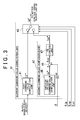
FIG. 2 is a block diagram illustrating the schematic configuration of a microcomputer; and -
FIG. 3 is a block diagram illustrating the schematic configuration of a current command value computation unit. - Hereinafter, a motor control unit 1 according to an embodiment of the invention will be described with reference to the accompanying drawings. The motor control unit 1 illustrated in
FIG. 1 is used to control the operation of amotor 2 used as a driving source for travelling of an electric vehicle, a hybrid vehicle, or the like. Themotor 2 is connected to awheel 4, which is an example of a driven body, via aclutch 3 that may function as an interrupting mechanism. When theclutch 3 is engaged, themotor 2 and thewheel 4 are connected to each other to allow torque transmission. On the other hand, when theclutch 3 is disengaged, themotor 2 and thewheel 4 are disconnected from each other to interrupt torque transmission. As themotor 2 in the present embodiment, a brushless motor is adopted. - As illustrated in
FIG. 1 , the motor control unit 1 includes amicrocomputer 11 that may function as a control circuit and that outputs a motor control signal S_m, and adriving circuit 12 that supplies driving electric power to themotor 2 on the basis of the motor control signal S_m output from themicrocomputer 11. As thedriving circuit 12 in the present embodiment, a known PWM inverter is adopted. In such a PWM inverter, a pair of switching elements (for example, FETs) connected in series is regarded as a basic unit. The PWM inverter is formed by connecting multiples pairs of the switching elements in parallel such that the pairs of switching elements respectively correspond to aU-phase motor coil 5u, a V-phase motor coil 5v, and a W-phase motor coil 5w. The motor control signal S_m output from themicrocomputer 11 is used to define the on-off state of each switching element. Each switching element is turned on or off in response to the motor control signal S_m and thus the energization patterns of theU-phase motor coil 5u, the V-phase motor coil 5v, and the W-phase motor coil 5w are switched. In this way, three-phase driving electric power is output to themotor 2. - The
microcomputer 11 is connected to a power supply (battery) 13 for control (hereinafter, referred to as "control power supply 13") through a power supply line Ls. Arelay circuit 14 formed by connecting, in parallel,control relays control relays control relays microcomputer 11 is actuated by the driving electric power supplied from thecontrol power supply 13. - The
driving circuit 12 is connected to a power supply (battery) 15 for driving (hereinafter, referred to as "driving power supply"), which may function as an external power supply, through a power supply line Lp. A capacitor C used to smooth an electric current supplied to the power supply line Lp is connected to the power supply line Lp. Adriving relay 16, which is a mechanical relay and which may function as a switch, is disposed on the power supply line Lp at a position closer to thedriving power supply 15 than the capacitor C. Thus, when thedriving relay 16 is turned on, the power supply line Lp is brought into conduction, whereas when drivingrelay 16 is turned off, the power supply line Lp is brought out of conduction. When the power supply line Lp is brought into conduction, thedriving circuit 12 is able to supply driving electric power based on the voltage of the power supply for driving 15 to themotor 2. - Vehicle signals such as an accelerator position signal ACCP indicating the depression amount of an accelerator pedal (not illustrated) of the vehicle, and an ignition signal S_ig indicating the on-off state of an ignition switch (IG) of the vehicle are input into the
microcomputer 11. In addition, signals indicating three-phase current values Iu, Iv, Iw of themotor 2, which are respectively detected bycurrent sensors motor 2, which is detected by arotation angle sensor 18, and a capacitor voltage Vc of the capacitor C, which is detected by avoltage sensor 19, are input into themicrocomputer 11. - The
microcomputer 11 outputs the motor control signal S_m, relay control signals S_rs, S_rp, and a clutch control signal S_cl on the basis of the received state quantities, and controls the operations of themotor 2, theclutch 3, thecontrol relay 14a, and thedriving relay 16. The ignition signal S_ig is directly input into thecontrol relay 14b. Thecontrol relay 14b operates to be in an on-state when the ignition signal S_ig indicates that the ignition switch is in an on-state (on-operation), and operates to be in an off-state when the ignition signal S_ig indicates that the ignition switch is in an off-state (off-operation). - Specifically, as illustrated in
FIG. 2 , themicrocomputer 11 includes amotor control unit 21 that outputs the motor control signal S_m, arelay control unit 22 that outputs the relay control signals S_rs, S_rp, and aclutch control unit 23 that outputs the clutch control signal S_cl. - The vehicle signals such as the accelerator position signal ACCP are input into the
motor control unit 21. Themotor control unit 21 includes a current commandvalue computation unit 31 that computes a current command value (a q-axis current command value Iq*) that is a target value of the electric power supply to themotor 2, and a motor controlsignal output unit 32 that outputs the motor control signal S_m on the basis of the current command value. - As illustrated in
FIG. 3 , a first commandvalue computation unit 41 is provided in the current commandvalue computation unit 31, and the vehicle signals such as the accelerator position signal ACCP are input into the first commandvalue computation unit 41. The first commandvalue computation unit 41 computes a first command value Iτ* corresponding to target torque based on the vehicle signals such as the accelerator position signal ACCP. A second commandvalue computation unit 42 and aswitching control unit 43, both of which will be described later, are provided in the current commandvalue computation unit 31. When the ignition signal S_ig indicates that the ignition switch is in the on-state, the first command value Iτ* is output to the motor controlsignal output unit 32 as the q-axis current command value Iq* in a two-phase rotating coordinate system (a d-q coordinate system) that rotates in accordance with the rotation angle θ. Note that, a d-axis current command value Id* is fixed at zero (Id* = 0). - As illustrated in
FIG. 2 , the three-phase phase current values Iu, Iv, Iw and the rotation angle θ are input into the motor controlsignal output unit 32 along with the q-axis current command value Iq* computed by the current commandvalue computation unit 31. The motor controlsignal output unit 32 executes current feedback control in the d-q coordinate system on the basis of the state quantities, thereby computing the motor control signal S_m that is output to the drivingcircuit 12. - Specifically, the three-phase current values Iu, Iv, Iw input into the motor control
signal output unit 32 are input into ad-q conversion unit 33. Thed-q conversion unit 33 computes a d-axis current value Id and a q-axis current value Iq by mapping the three-phase current values Iu, Iv, Iw onto the d-q coordinates on the basis of the rotation angle θ. Subsequently, the q-axis current value Iq is input into asubtracter 34q along with the q-axis current command value Iq* received from the current commandvalue computation unit 31, and the d-axis current value Id is input into asubtracter 34d along with the d-axis current command value Id*. Then, thesubtracters - The d-axis current deviation ΔId and the q-axis current deviation ΔIq are input into feedback (FB)
control units FB control units - The d-axis voltage command value Vd* and the q-axis voltage command value Vq* are input into a d-q
reverse conversion unit 36 along with the rotation angle θ. The d-qreverse conversion unit 36 compute three-phase voltage command values Vu*, Vv*, Vw* by mapping the d-axis voltage command value Vd* and the q-axis voltage command value Vq* onto the three-phase alternating-current coordinates on the basis of the rotation angle θ. Subsequently, the three-phase voltage command values Vu*, Vv*, Vw* are input into aPWM conversion unit 37. ThePWM conversion unit 37 computes duty command values based on the three-phase voltage command values Vu*, Vv*, Vw*, generates the motor control signal S_m having an on-duty ratio indicated by each duty command value, and outputs the motor control signal S_m to the drivingcircuit 12. In this way, driving electric power based on the motor control signal S_m is output to themotor 2, and motor torque corresponding to the driving electric power is transmitted to thewheel 4 via theclutch 3. - The ignition signal S_ig and the capacitor voltage Vc detected by the voltage sensor 19 (refer to
FIG. 1 ) are input into therelay control unit 22. When the ignition signal S_ig indicates that the ignition switch is in the on-state, therelay control unit 22 outputs the relay control signals S_rs, S_rp such that thecontrol relay 14a and the drivingrelay 16 are turned on (brought into the on-operation). On the other hand, when the ignition signal S_ig indicates that the ignition switch is in the off-state, therelay control unit 22 first outputs the relay control signal S_rp such that the drivingrelay 16 is turned off (brought into the off-operation). Then, when the capacitor voltage Vc becomes less than or equal to a prescribed capacitor voltage Vcth set in advance, therelay control unit 22 outputs the relay control signal S_rs such that thecontrol relay 14a is turned off (brought into the off-operation). - The ignition signal S_ig is input into the
clutch control unit 23. When the ignition signal S_ig indicates that the ignition switch is in the on-state, theclutch control unit 23 outputs the clutch control signal S_cl such that theclutch 3 is engaged. On the other hand, when the ignition signal S_ig indicates that the ignition switch is in the off-state, theclutch control unit 23 outputs the clutch control signal S_cl such that theclutch 3 is disengaged. - When the ignition switch is turned off by a driver to stop the supply of driving electric power to the
motor 2, themicrocomputer 11 carries out electric discharge from the capacitor C by supplying the electric power, which is generated by electric charges stored in the capacitor C, to themotor 2 such that torque is generated (without setting the q-axis current command value Iq* to zero). At this time, themicrocomputer 11 in the present embodiment controls the electric power that is supplied to themotor 2 such that an angular velocity ω of themotor 2 becomes less than or equal to a prescribed angular velocity ωth. Note that, the prescribed angular velocity ωth is set less than or equal to the maximum angular velocity at which themotor 2 is able to rotate with the clutch 3 engaged, and set to be an angular velocity sufficiently smaller than the maximum angular velocity at which themotor 2 is able to rotate with the clutch 3 disengaged, that is, with no load placed on themotor 2. - Specifically, as illustrated in
FIG. 3 , in addition to the first commandvalue computation unit 41, the second commandvalue computation unit 42 and the switchingcontrol unit 43 are provided in the current commandvalue computation unit 31, and an angular velocity commandvalue computation unit 45 that computes an angular velocity command value ω* that is a target angular velocity of themotor 2 is provided in the second commandvalue computation unit 42. The second commandvalue computation unit 42 computes a second command value Iω*, which is a target value of the electric power supply to themotor 2 at the time of electric discharge from the capacitor C, by executing velocity feedback control so as to cause the angular velocity ω of themotor 2 to follow the angular velocity command value ω* computed by the angular velocity commandvalue computation unit 45. - Specifically, the angular velocity command
value computation unit 45 outputs a value less than or equal to the prescribed angular velocity ωth to asubtracter 46 as the angular velocity command value ω*. The angular velocity (rotation angular velocity) ω of themotor 2, which is obtained by differentiating the rotation angle θ detected by the rotation angle sensor 18 (refer toFIG. 1 ), is input into thesubtracter 46 along with the angular velocity command value ω* In the present embodiment, themicrocomputer 11 and therotation angle sensor 18 constitute an angular velocity detector. Thesubtracter 46 computes an angular velocity deviation Δω that is a deviation (difference) between the angular velocity command value ω* and the angular velocity ω, and outputs the angular velocity deviation Δω to a feedback (FB)control unit 47. TheFB control unit 47 computes the second command value Iω* by multiplying the angular velocity deviation Δω by a prescribed gain so as to cause the angular velocity ω to follow the angular velocity command value ω*, and outputs the second command value Iω* to the switchingcontrol unit 43. - The ignition signal S_ig, the relay control signal S_rp, and the clutch control signal S_cl are input into the switching
control unit 43. When the ignition signal S_ig indicates that the ignition switch is in the on-state, the switchingcontrol unit 43 outputs the first command value Iτ* as the q-axis current command value Iq*. On the other hand, when the ignition signal S_ig indicates that the ignition switch is in the off-state, the drivingrelay 16 is turned off according to the relay control signal S_rp, and theclutch 3 is disengaged according to the clutch control signal S_cl, the switchingcontrol unit 43 outputs the second command value Iω* as the q-axis current command value Iq*. In this way, when electric discharge from the capacitor C is carried out, the q-axis current command value Iq* that makes the angular velocity ω of themotor 2 less than or equal to the prescribed angular velocity ωth is output to the motor controlsignal output unit 32. - The operation of the present embodiment will be described below. When the ignition switch is turned off by a driver, the
control relay 14b and the drivingrelay 16 are turned off and theclutch 3 is disengaged. Further, the motor control signal S_m based on the q-axis current command value Iq* (the second command value Iω*) that makes the angular velocity ω of themotor 2 less than or equal to the prescribed angular velocity cosh is output from themicrocomputer 11 to the drivingcircuit 12. In this way, the electric power generated by the electric charges stored in the capacitor C is controlled and supplied to themotor 2 such that torque is generated and the angular velocity ω becomes less than or equal to the prescribed angular velocity ωth, and electric discharge from the capacitor C is carried out. When the capacitor voltage Vc becomes less than or equal to the prescribed capacitor voltage Vcth, thecontrol relay 14a is turned off and the electric power supply to themicrocomputer 11 is stopped. As a result, the motor control unit 1 is shut down. - The advantageous effects of the present embodiment will be described. Because the electric power generated by the electric charges stored in the capacitor C is supplied to the
motor 2 such that torque is generated, it is possible to carry out electric discharge from the capacitor C while suppressing resistance heating. In the present embodiment, when electric discharge from the capacitor C is carried out, the angular velocity ω of themotor 2 is controlled so as to become less than or equal to the prescribed angular velocity ωth. Therefore, even if electric power is supplied to themotor 2 with torque transmission between themotor 2 and thewheel 4 interrupted, themotor 2 is prevented from rotating an excessively high angular velocity ω. In this way, it is possible to prevent an excessive burden from being placed on themotor 2 itself and its peripheral components such as a bearing. - The embodiment described above may be modified as follows. In the embodiment described above, the velocity feedback control is executed. Thus, when electric discharge from the capacitor C is carried out, electric power is supplied to the
motor 2 such that the angular velocity ω of themotor 2 becomes less than or equal to the prescribed angular velocity ωth. However, the invention is not limited to this. For example, on the basis the fact that the angular velocity ω of themotor 2 is proportional to the voltage applied to themotor 2, when electric discharge from the capacitor C is carried out, the angular velocity ω of themotor 2 may be made less than or equal to the prescribed angular velocity ωth by supplying electric power to themotor 2 with, for example, the three-phase voltage command values Vu*, Vv*, Vw* fixed at values less than or equal to a prescribed voltage (voltage at which the angular velocity ω of themotor 2 becomes less than or equal to the prescribed angular velocity ωth). Note that, in this case, the rotation angle θ (the angular velocity ω) of themotor 2 need not be detected. - In the embodiment described above, a relay sensor that detects the on-off state of the driving
relay 16 may be provided and a determination that the drivingrelay 16 is in the off-state, which is made based on a signal from the relay sensor, may be added to the conditions under which theswitching control unit 43 outputs the second command value Iω* as the q-axis current command value Iq*. A clutch sensor that detects the state of the clutch 3 may be provided and a determination that theclutch 3 is disengaged, which is made based on a signal from the clutch sensor, may be added to the conditions under which theswitching control unit 43 outputs the second command value Iω* as the q-axis current command value Iq*. - In the embodiment described above, the
microcomputer 11 includes therelay control unit 22. However, the invention is not limited to this. For example, a control unit that controls the operations of thecontrol relay 14a and the drivingrelay 16 may be provided in addition to the motor control unit 1, and themicrocomputer 11 may include norelay control unit 22. Similarly, a control unit that controls the operation of the clutch 3 may be provided in addition to the motor control unit 1, and themicrocomputer 11 may include noclutch control unit 23. In these cases, a determination that the drivingrelay 16 is in the off-state, which is made based on a signal from the relay sensor, or a determination that theclutch 3 is disengaged, which is made based on a signal from the clutch sensor, may be added to the conditions under which theswitching control unit 43 outputs the second command value Iω* as the q-axis current command value Iq*. - In the embodiment described above, a mechanical relay is used as the driving
relay 16 that serves as a switch. However, the invention is not limited to this. For example, a switching element such as a FET (field effect transistor) may be used as the drivingrelay 16. Similarly, a switching element such as a FET may be used as each of the control relays 14a, 14b. - In the embodiment described above, a brushless motor is used as the
motor 2. However, the invention is not limited to this. For example, a direct-current motor with a brush may be used as themotor 2. In the embodiment described above, the operation of themotor 2 connected to thewheel 4 is controlled by the motor control unit 1. However, the invention is not limited to this. The operation of a motor for other uses may be controlled by the motor control unit 1. - Next, the technical concept that is understood from the embodiment described above and the modified examples will be described below. There is provided a motor control unit in which a control circuit supplies electric power to a motor such that an angular velocity of the motor becomes less than or equal to a prescribed angular velocity, by executing velocity feedback control so as to cause the angular velocity of the motor that is detected by an angular velocity detector to follow a target angular velocity.
- There is provided the motor control unit in which the control circuit supplies electric power to the motor such that the angular velocity of the motor becomes less than or equal to the prescribed angular velocity, by making a voltage that is applied to the motor less than or equal to a prescribed voltage.
- A motor control unit (1) controls an operation of a motor (2) connected to a wheel (4) via a clutch (3) that allows or interrupts torque transmission between the motor (2) and the wheel (4). The motor control unit (1) includes: a microcomputer (11) that outputs a motor control signal S_m; a driving circuit (12) that supplies driving electric power to the motor (2) based on the motor control signal S_m; and a capacitor (C) provided at an intermediate portion of a power supply line (Lp) that connects the driving circuit (12) and a driving power supply (15) to each other. The microcomputer (11) carries out electric discharge from the capacitor (C) by supplying electric power generated by electric charges stored in the capacitor (C) to the motor (2) such that torque is generated by the motor (2) and an angular velocity of the motor (2) becomes less than or equal to a prescribed angular velocity, with torque transmission between the motor (2) and the wheel (4) interrupted by the clutch (3), after a driving relay (16) is turned off.
Claims (1)
- A motor control unit that controls an operation of a motor connected to a driven body via an interrupting mechanism that allows or interrupts torque transmission between the motor and the driven body, comprising:a control circuit that outputs a motor control signal for controlling the operation of the motor;a driving circuit that supplies driving electric power to the motor based on the motor control signal; anda capacitor provided at an intermediate portion of a power supply line that connects the driving circuit and an external power supply to each other, whereinthe control circuit carries out electric discharge from the capacitor by supplying electric power generated by electric charges stored in the capacitor to the motor such that torque is generated by the motor, with torque transmission between the motor and the driven body interrupted by the interrupting mechanism, after a switch provided at an intermediate portion of the power supply line is turned off, andthe control circuit controls electric power supply to the motor such that an angular velocity of the motor becomes less than or equal to a prescribed angular velocity, at the time of the electric discharge from the capacitor.
Applications Claiming Priority (1)
| Application Number | Priority Date | Filing Date | Title |
|---|---|---|---|
| JP2013046928A JP6155708B2 (en) | 2013-03-08 | 2013-03-08 | Motor control device |
Publications (3)
| Publication Number | Publication Date |
|---|---|
| EP2775607A2 true EP2775607A2 (en) | 2014-09-10 |
| EP2775607A3 EP2775607A3 (en) | 2017-12-20 |
| EP2775607B1 EP2775607B1 (en) | 2019-08-21 |
Family
ID=50193372
Family Applications (1)
| Application Number | Title | Priority Date | Filing Date |
|---|---|---|---|
| EP14158033.2A Active EP2775607B1 (en) | 2013-03-08 | 2014-03-06 | Motor control unit |
Country Status (4)
| Country | Link |
|---|---|
| US (1) | US20140253003A1 (en) |
| EP (1) | EP2775607B1 (en) |
| JP (1) | JP6155708B2 (en) |
| CN (1) | CN104038126B (en) |
Families Citing this family (1)
| Publication number | Priority date | Publication date | Assignee | Title |
|---|---|---|---|---|
| US12088156B2 (en) * | 2022-06-28 | 2024-09-10 | Ford Global Technologies, Llc | Rotor position-based ramp rate to reduce vehicle harshness during active discharge |
Citations (1)
| Publication number | Priority date | Publication date | Assignee | Title |
|---|---|---|---|---|
| JPH1189264A (en) | 1997-09-04 | 1999-03-30 | Yaskawa Electric Corp | Main circuit power supply discharging method |
Family Cites Families (16)
| Publication number | Priority date | Publication date | Assignee | Title |
|---|---|---|---|---|
| JPS6020870A (en) * | 1983-07-12 | 1985-02-02 | 日立工機株式会社 | Control system of clutch type motorized clamping tool |
| JP3425730B2 (en) * | 1998-03-31 | 2003-07-14 | 本田技研工業株式会社 | Control device for hybrid vehicle |
| JP4006948B2 (en) * | 2001-02-14 | 2007-11-14 | スズキ株式会社 | Vehicle power generation control device |
| US7268521B1 (en) * | 2003-09-26 | 2007-09-11 | Ford Global Technologies, Llc | Method and system for discharging a capacitive element in an electrically operable vehicle |
| JP4648054B2 (en) * | 2005-03-31 | 2011-03-09 | 日立オートモティブシステムズ株式会社 | Hybrid vehicle, control device for electric drive device and electric drive device |
| JP4797537B2 (en) * | 2005-09-22 | 2011-10-19 | 日産自動車株式会社 | Motor control device |
| JP4179381B2 (en) * | 2007-01-25 | 2008-11-12 | トヨタ自動車株式会社 | Electric vehicle |
| US7779941B1 (en) * | 2007-03-21 | 2010-08-24 | Honda Motor Co., Ltd. | Method and apparatus for delivery cart movement start and energy recovery |
| JP4609489B2 (en) * | 2007-12-25 | 2011-01-12 | パナソニック電工株式会社 | Electric tool |
| JP5284028B2 (en) * | 2008-10-01 | 2013-09-11 | 株式会社ジェイテクト | Electric power steering device |
| JP4968698B2 (en) * | 2008-12-26 | 2012-07-04 | 本田技研工業株式会社 | Electric motor control device |
| JP5056781B2 (en) * | 2009-03-12 | 2012-10-24 | 株式会社デンソー | Navigation device |
| RU2482599C1 (en) * | 2009-05-13 | 2013-05-20 | Мицубиси Электрик Корпорейшн | Energy conversion device and method of voltage control on capacitor of energy conversion device |
| JP4911231B2 (en) * | 2010-02-15 | 2012-04-04 | 株式会社デンソー | Rotating electrical machine control device and electric power steering device using the same |
| JP5201192B2 (en) * | 2010-10-15 | 2013-06-05 | 株式会社デンソー | Rotating machine control device |
| JP5397432B2 (en) * | 2011-08-22 | 2014-01-22 | トヨタ自動車株式会社 | Rotating electrical machine drive system |
-
2013
- 2013-03-08 JP JP2013046928A patent/JP6155708B2/en not_active Expired - Fee Related
-
2014
- 2014-03-04 US US14/196,056 patent/US20140253003A1/en not_active Abandoned
- 2014-03-05 CN CN201410077977.3A patent/CN104038126B/en not_active Expired - Fee Related
- 2014-03-06 EP EP14158033.2A patent/EP2775607B1/en active Active
Patent Citations (1)
| Publication number | Priority date | Publication date | Assignee | Title |
|---|---|---|---|---|
| JPH1189264A (en) | 1997-09-04 | 1999-03-30 | Yaskawa Electric Corp | Main circuit power supply discharging method |
Also Published As
| Publication number | Publication date |
|---|---|
| CN104038126B (en) | 2018-04-27 |
| JP2014176202A (en) | 2014-09-22 |
| CN104038126A (en) | 2014-09-10 |
| EP2775607B1 (en) | 2019-08-21 |
| JP6155708B2 (en) | 2017-07-05 |
| US20140253003A1 (en) | 2014-09-11 |
| EP2775607A3 (en) | 2017-12-20 |
Similar Documents
| Publication | Publication Date | Title |
|---|---|---|
| US9903931B2 (en) | Diagnostic device for voltage sensors | |
| JP2010057228A (en) | Motor control device | |
| JP2010221856A (en) | Steering control device | |
| CN104417604A (en) | Electric power steering system | |
| WO2010021353A1 (en) | Motor control device and electric power steering device | |
| JP6500653B2 (en) | Control device of inverter | |
| CN109747703B (en) | Steering control device | |
| JP2014135866A (en) | Motor controller and electrically-driven power steering device | |
| JP2017139926A (en) | Driving device | |
| JP2011125134A (en) | Motor control apparatus | |
| CN112166050A (en) | Inverter control method and inverter control system | |
| JP6421710B2 (en) | Inverter control device | |
| EP3495235B1 (en) | Steering control unit | |
| EP2775607B1 (en) | Motor control unit | |
| JP2011015594A (en) | Motor controller | |
| JP2015023611A (en) | Electric vehicle | |
| JP2015073404A (en) | Temperature estimation device | |
| JP2011250616A (en) | Motor drive device and motor driven vehicle | |
| JP5595436B2 (en) | Motor control device | |
| JP6708843B2 (en) | Drive | |
| JP2015047878A (en) | Electric power steering device | |
| JP5480115B2 (en) | Power steering device | |
| JP7091669B2 (en) | Electric vehicle | |
| JP6939444B2 (en) | Drive device | |
| JP2024044729A (en) | Electric vehicles |
Legal Events
| Date | Code | Title | Description |
|---|---|---|---|
| PUAI | Public reference made under article 153(3) epc to a published international application that has entered the european phase |
Free format text: ORIGINAL CODE: 0009012 |
|
| 17P | Request for examination filed |
Effective date: 20140306 |
|
| AK | Designated contracting states |
Kind code of ref document: A2 Designated state(s): AL AT BE BG CH CY CZ DE DK EE ES FI FR GB GR HR HU IE IS IT LI LT LU LV MC MK MT NL NO PL PT RO RS SE SI SK SM TR |
|
| AX | Request for extension of the european patent |
Extension state: BA ME |
|
| PUAL | Search report despatched |
Free format text: ORIGINAL CODE: 0009013 |
|
| AK | Designated contracting states |
Kind code of ref document: A3 Designated state(s): AL AT BE BG CH CY CZ DE DK EE ES FI FR GB GR HR HU IE IS IT LI LT LU LV MC MK MT NL NO PL PT RO RS SE SI SK SM TR |
|
| AX | Request for extension of the european patent |
Extension state: BA ME |
|
| RIC1 | Information provided on ipc code assigned before grant |
Ipc: B60L 11/00 20060101ALI20171113BHEP Ipc: H02P 6/20 20160101AFI20171113BHEP |
|
| STAA | Information on the status of an ep patent application or granted ep patent |
Free format text: STATUS: REQUEST FOR EXAMINATION WAS MADE |
|
| R17P | Request for examination filed (corrected) |
Effective date: 20180619 |
|
| STAA | Information on the status of an ep patent application or granted ep patent |
Free format text: STATUS: EXAMINATION IS IN PROGRESS |
|
| 17Q | First examination report despatched |
Effective date: 20181009 |
|
| REG | Reference to a national code |
Ref country code: DE Ref legal event code: R079 Ref document number: 602014052031 Country of ref document: DE Free format text: PREVIOUS MAIN CLASS: H02P0006200000 Ipc: B60L0050400000 |
|
| RIC1 | Information provided on ipc code assigned before grant |
Ipc: B60L 50/40 20190101AFI20190211BHEP |
|
| GRAP | Despatch of communication of intention to grant a patent |
Free format text: ORIGINAL CODE: EPIDOSNIGR1 |
|
| STAA | Information on the status of an ep patent application or granted ep patent |
Free format text: STATUS: GRANT OF PATENT IS INTENDED |
|
| INTG | Intention to grant announced |
Effective date: 20190322 |
|
| GRAS | Grant fee paid |
Free format text: ORIGINAL CODE: EPIDOSNIGR3 |
|
| GRAA | (expected) grant |
Free format text: ORIGINAL CODE: 0009210 |
|
| STAA | Information on the status of an ep patent application or granted ep patent |
Free format text: STATUS: THE PATENT HAS BEEN GRANTED |
|
| AK | Designated contracting states |
Kind code of ref document: B1 Designated state(s): AL AT BE BG CH CY CZ DE DK EE ES FI FR GB GR HR HU IE IS IT LI LT LU LV MC MK MT NL NO PL PT RO RS SE SI SK SM TR |
|
| REG | Reference to a national code |
Ref country code: GB Ref legal event code: FG4D |
|
| REG | Reference to a national code |
Ref country code: CH Ref legal event code: EP |
|
| REG | Reference to a national code |
Ref country code: DE Ref legal event code: R096 Ref document number: 602014052031 Country of ref document: DE |
|
| REG | Reference to a national code |
Ref country code: AT Ref legal event code: REF Ref document number: 1169346 Country of ref document: AT Kind code of ref document: T Effective date: 20190915 |
|
| REG | Reference to a national code |
Ref country code: IE Ref legal event code: FG4D |
|
| REG | Reference to a national code |
Ref country code: LT Ref legal event code: MG4D |
|
| REG | Reference to a national code |
Ref country code: NL Ref legal event code: MP Effective date: 20190821 |
|
| PG25 | Lapsed in a contracting state [announced via postgrant information from national office to epo] |
Ref country code: PT Free format text: LAPSE BECAUSE OF FAILURE TO SUBMIT A TRANSLATION OF THE DESCRIPTION OR TO PAY THE FEE WITHIN THE PRESCRIBED TIME-LIMIT Effective date: 20191223 Ref country code: LT Free format text: LAPSE BECAUSE OF FAILURE TO SUBMIT A TRANSLATION OF THE DESCRIPTION OR TO PAY THE FEE WITHIN THE PRESCRIBED TIME-LIMIT Effective date: 20190821 Ref country code: BG Free format text: LAPSE BECAUSE OF FAILURE TO SUBMIT A TRANSLATION OF THE DESCRIPTION OR TO PAY THE FEE WITHIN THE PRESCRIBED TIME-LIMIT Effective date: 20191121 Ref country code: SE Free format text: LAPSE BECAUSE OF FAILURE TO SUBMIT A TRANSLATION OF THE DESCRIPTION OR TO PAY THE FEE WITHIN THE PRESCRIBED TIME-LIMIT Effective date: 20190821 Ref country code: NL Free format text: LAPSE BECAUSE OF FAILURE TO SUBMIT A TRANSLATION OF THE DESCRIPTION OR TO PAY THE FEE WITHIN THE PRESCRIBED TIME-LIMIT Effective date: 20190821 Ref country code: NO Free format text: LAPSE BECAUSE OF FAILURE TO SUBMIT A TRANSLATION OF THE DESCRIPTION OR TO PAY THE FEE WITHIN THE PRESCRIBED TIME-LIMIT Effective date: 20191121 Ref country code: HR Free format text: LAPSE BECAUSE OF FAILURE TO SUBMIT A TRANSLATION OF THE DESCRIPTION OR TO PAY THE FEE WITHIN THE PRESCRIBED TIME-LIMIT Effective date: 20190821 Ref country code: FI Free format text: LAPSE BECAUSE OF FAILURE TO SUBMIT A TRANSLATION OF THE DESCRIPTION OR TO PAY THE FEE WITHIN THE PRESCRIBED TIME-LIMIT Effective date: 20190821 |
|
| PG25 | Lapsed in a contracting state [announced via postgrant information from national office to epo] |
Ref country code: IS Free format text: LAPSE BECAUSE OF FAILURE TO SUBMIT A TRANSLATION OF THE DESCRIPTION OR TO PAY THE FEE WITHIN THE PRESCRIBED TIME-LIMIT Effective date: 20191221 Ref country code: ES Free format text: LAPSE BECAUSE OF FAILURE TO SUBMIT A TRANSLATION OF THE DESCRIPTION OR TO PAY THE FEE WITHIN THE PRESCRIBED TIME-LIMIT Effective date: 20190821 Ref country code: RS Free format text: LAPSE BECAUSE OF FAILURE TO SUBMIT A TRANSLATION OF THE DESCRIPTION OR TO PAY THE FEE WITHIN THE PRESCRIBED TIME-LIMIT Effective date: 20190821 Ref country code: GR Free format text: LAPSE BECAUSE OF FAILURE TO SUBMIT A TRANSLATION OF THE DESCRIPTION OR TO PAY THE FEE WITHIN THE PRESCRIBED TIME-LIMIT Effective date: 20191122 Ref country code: AL Free format text: LAPSE BECAUSE OF FAILURE TO SUBMIT A TRANSLATION OF THE DESCRIPTION OR TO PAY THE FEE WITHIN THE PRESCRIBED TIME-LIMIT Effective date: 20190821 Ref country code: LV Free format text: LAPSE BECAUSE OF FAILURE TO SUBMIT A TRANSLATION OF THE DESCRIPTION OR TO PAY THE FEE WITHIN THE PRESCRIBED TIME-LIMIT Effective date: 20190821 |
|
| REG | Reference to a national code |
Ref country code: AT Ref legal event code: MK05 Ref document number: 1169346 Country of ref document: AT Kind code of ref document: T Effective date: 20190821 |
|
| PG25 | Lapsed in a contracting state [announced via postgrant information from national office to epo] |
Ref country code: TR Free format text: LAPSE BECAUSE OF FAILURE TO SUBMIT A TRANSLATION OF THE DESCRIPTION OR TO PAY THE FEE WITHIN THE PRESCRIBED TIME-LIMIT Effective date: 20190821 |
|
| PG25 | Lapsed in a contracting state [announced via postgrant information from national office to epo] |
Ref country code: RO Free format text: LAPSE BECAUSE OF FAILURE TO SUBMIT A TRANSLATION OF THE DESCRIPTION OR TO PAY THE FEE WITHIN THE PRESCRIBED TIME-LIMIT Effective date: 20190821 Ref country code: DK Free format text: LAPSE BECAUSE OF FAILURE TO SUBMIT A TRANSLATION OF THE DESCRIPTION OR TO PAY THE FEE WITHIN THE PRESCRIBED TIME-LIMIT Effective date: 20190821 Ref country code: IT Free format text: LAPSE BECAUSE OF FAILURE TO SUBMIT A TRANSLATION OF THE DESCRIPTION OR TO PAY THE FEE WITHIN THE PRESCRIBED TIME-LIMIT Effective date: 20190821 Ref country code: AT Free format text: LAPSE BECAUSE OF FAILURE TO SUBMIT A TRANSLATION OF THE DESCRIPTION OR TO PAY THE FEE WITHIN THE PRESCRIBED TIME-LIMIT Effective date: 20190821 Ref country code: EE Free format text: LAPSE BECAUSE OF FAILURE TO SUBMIT A TRANSLATION OF THE DESCRIPTION OR TO PAY THE FEE WITHIN THE PRESCRIBED TIME-LIMIT Effective date: 20190821 Ref country code: PL Free format text: LAPSE BECAUSE OF FAILURE TO SUBMIT A TRANSLATION OF THE DESCRIPTION OR TO PAY THE FEE WITHIN THE PRESCRIBED TIME-LIMIT Effective date: 20190821 |
|
| PG25 | Lapsed in a contracting state [announced via postgrant information from national office to epo] |
Ref country code: CZ Free format text: LAPSE BECAUSE OF FAILURE TO SUBMIT A TRANSLATION OF THE DESCRIPTION OR TO PAY THE FEE WITHIN THE PRESCRIBED TIME-LIMIT Effective date: 20190821 Ref country code: IS Free format text: LAPSE BECAUSE OF FAILURE TO SUBMIT A TRANSLATION OF THE DESCRIPTION OR TO PAY THE FEE WITHIN THE PRESCRIBED TIME-LIMIT Effective date: 20200224 Ref country code: SK Free format text: LAPSE BECAUSE OF FAILURE TO SUBMIT A TRANSLATION OF THE DESCRIPTION OR TO PAY THE FEE WITHIN THE PRESCRIBED TIME-LIMIT Effective date: 20190821 Ref country code: SM Free format text: LAPSE BECAUSE OF FAILURE TO SUBMIT A TRANSLATION OF THE DESCRIPTION OR TO PAY THE FEE WITHIN THE PRESCRIBED TIME-LIMIT Effective date: 20190821 |
|
| REG | Reference to a national code |
Ref country code: DE Ref legal event code: R097 Ref document number: 602014052031 Country of ref document: DE |
|
| PLBE | No opposition filed within time limit |
Free format text: ORIGINAL CODE: 0009261 |
|
| STAA | Information on the status of an ep patent application or granted ep patent |
Free format text: STATUS: NO OPPOSITION FILED WITHIN TIME LIMIT |
|
| PG2D | Information on lapse in contracting state deleted |
Ref country code: IS |
|
| 26N | No opposition filed |
Effective date: 20200603 |
|
| PG25 | Lapsed in a contracting state [announced via postgrant information from national office to epo] |
Ref country code: SI Free format text: LAPSE BECAUSE OF FAILURE TO SUBMIT A TRANSLATION OF THE DESCRIPTION OR TO PAY THE FEE WITHIN THE PRESCRIBED TIME-LIMIT Effective date: 20190821 |
|
| REG | Reference to a national code |
Ref country code: DE Ref legal event code: R119 Ref document number: 602014052031 Country of ref document: DE |
|
| PG25 | Lapsed in a contracting state [announced via postgrant information from national office to epo] |
Ref country code: MC Free format text: LAPSE BECAUSE OF FAILURE TO SUBMIT A TRANSLATION OF THE DESCRIPTION OR TO PAY THE FEE WITHIN THE PRESCRIBED TIME-LIMIT Effective date: 20190821 |
|
| REG | Reference to a national code |
Ref country code: CH Ref legal event code: PL |
|
| REG | Reference to a national code |
Ref country code: BE Ref legal event code: MM Effective date: 20200331 |
|
| PG25 | Lapsed in a contracting state [announced via postgrant information from national office to epo] |
Ref country code: LU Free format text: LAPSE BECAUSE OF NON-PAYMENT OF DUE FEES Effective date: 20200306 |
|
| PG25 | Lapsed in a contracting state [announced via postgrant information from national office to epo] |
Ref country code: DE Free format text: LAPSE BECAUSE OF NON-PAYMENT OF DUE FEES Effective date: 20201001 Ref country code: IE Free format text: LAPSE BECAUSE OF NON-PAYMENT OF DUE FEES Effective date: 20200306 Ref country code: LI Free format text: LAPSE BECAUSE OF NON-PAYMENT OF DUE FEES Effective date: 20200331 Ref country code: CH Free format text: LAPSE BECAUSE OF NON-PAYMENT OF DUE FEES Effective date: 20200331 Ref country code: FR Free format text: LAPSE BECAUSE OF NON-PAYMENT OF DUE FEES Effective date: 20200331 |
|
| PG25 | Lapsed in a contracting state [announced via postgrant information from national office to epo] |
Ref country code: BE Free format text: LAPSE BECAUSE OF NON-PAYMENT OF DUE FEES Effective date: 20200331 |
|
| GBPC | Gb: european patent ceased through non-payment of renewal fee |
Effective date: 20200306 |
|
| PG25 | Lapsed in a contracting state [announced via postgrant information from national office to epo] |
Ref country code: GB Free format text: LAPSE BECAUSE OF NON-PAYMENT OF DUE FEES Effective date: 20200306 |
|
| PG25 | Lapsed in a contracting state [announced via postgrant information from national office to epo] |
Ref country code: MT Free format text: LAPSE BECAUSE OF FAILURE TO SUBMIT A TRANSLATION OF THE DESCRIPTION OR TO PAY THE FEE WITHIN THE PRESCRIBED TIME-LIMIT Effective date: 20190821 Ref country code: CY Free format text: LAPSE BECAUSE OF FAILURE TO SUBMIT A TRANSLATION OF THE DESCRIPTION OR TO PAY THE FEE WITHIN THE PRESCRIBED TIME-LIMIT Effective date: 20190821 |
|
| PG25 | Lapsed in a contracting state [announced via postgrant information from national office to epo] |
Ref country code: MK Free format text: LAPSE BECAUSE OF FAILURE TO SUBMIT A TRANSLATION OF THE DESCRIPTION OR TO PAY THE FEE WITHIN THE PRESCRIBED TIME-LIMIT Effective date: 20190821 |