EP2775357A2 - Image heating apparatus - Google Patents
Image heating apparatus Download PDFInfo
- Publication number
- EP2775357A2 EP2775357A2 EP14156509.3A EP14156509A EP2775357A2 EP 2775357 A2 EP2775357 A2 EP 2775357A2 EP 14156509 A EP14156509 A EP 14156509A EP 2775357 A2 EP2775357 A2 EP 2775357A2
- Authority
- EP
- European Patent Office
- Prior art keywords
- pressing
- arm
- unit
- heating apparatus
- abutting
- Prior art date
- Legal status (The legal status is an assumption and is not a legal conclusion. Google has not performed a legal analysis and makes no representation as to the accuracy of the status listed.)
- Granted
Links
Images




Classifications
-
- G—PHYSICS
- G03—PHOTOGRAPHY; CINEMATOGRAPHY; ANALOGOUS TECHNIQUES USING WAVES OTHER THAN OPTICAL WAVES; ELECTROGRAPHY; HOLOGRAPHY
- G03G—ELECTROGRAPHY; ELECTROPHOTOGRAPHY; MAGNETOGRAPHY
- G03G15/00—Apparatus for electrographic processes using a charge pattern
- G03G15/20—Apparatus for electrographic processes using a charge pattern for fixing, e.g. by using heat
- G03G15/2003—Apparatus for electrographic processes using a charge pattern for fixing, e.g. by using heat using heat
- G03G15/2014—Apparatus for electrographic processes using a charge pattern for fixing, e.g. by using heat using heat using contact heat
- G03G15/206—Structural details or chemical composition of the pressure elements and layers thereof
-
- G—PHYSICS
- G03—PHOTOGRAPHY; CINEMATOGRAPHY; ANALOGOUS TECHNIQUES USING WAVES OTHER THAN OPTICAL WAVES; ELECTROGRAPHY; HOLOGRAPHY
- G03G—ELECTROGRAPHY; ELECTROPHOTOGRAPHY; MAGNETOGRAPHY
- G03G15/00—Apparatus for electrographic processes using a charge pattern
- G03G15/20—Apparatus for electrographic processes using a charge pattern for fixing, e.g. by using heat
- G03G15/2003—Apparatus for electrographic processes using a charge pattern for fixing, e.g. by using heat using heat
- G03G15/2014—Apparatus for electrographic processes using a charge pattern for fixing, e.g. by using heat using heat using contact heat
- G03G15/2017—Structural details of the fixing unit in general, e.g. cooling means, heat shielding means
- G03G15/2032—Retractable heating or pressure unit
-
- G—PHYSICS
- G03—PHOTOGRAPHY; CINEMATOGRAPHY; ANALOGOUS TECHNIQUES USING WAVES OTHER THAN OPTICAL WAVES; ELECTROGRAPHY; HOLOGRAPHY
- G03G—ELECTROGRAPHY; ELECTROPHOTOGRAPHY; MAGNETOGRAPHY
- G03G15/00—Apparatus for electrographic processes using a charge pattern
- G03G15/20—Apparatus for electrographic processes using a charge pattern for fixing, e.g. by using heat
- G03G15/2003—Apparatus for electrographic processes using a charge pattern for fixing, e.g. by using heat using heat
- G03G15/2014—Apparatus for electrographic processes using a charge pattern for fixing, e.g. by using heat using heat using contact heat
- G03G15/2064—Apparatus for electrographic processes using a charge pattern for fixing, e.g. by using heat using heat using contact heat combined with pressure
-
- G—PHYSICS
- G03—PHOTOGRAPHY; CINEMATOGRAPHY; ANALOGOUS TECHNIQUES USING WAVES OTHER THAN OPTICAL WAVES; ELECTROGRAPHY; HOLOGRAPHY
- G03G—ELECTROGRAPHY; ELECTROPHOTOGRAPHY; MAGNETOGRAPHY
- G03G21/00—Arrangements not provided for by groups G03G13/00 - G03G19/00, e.g. cleaning, elimination of residual charge
- G03G21/16—Mechanical means for facilitating the maintenance of the apparatus, e.g. modular arrangements
- G03G21/1604—Arrangement or disposition of the entire apparatus
- G03G21/1623—Means to access the interior of the apparatus
- G03G21/1633—Means to access the interior of the apparatus using doors or covers
-
- G—PHYSICS
- G03—PHOTOGRAPHY; CINEMATOGRAPHY; ANALOGOUS TECHNIQUES USING WAVES OTHER THAN OPTICAL WAVES; ELECTROGRAPHY; HOLOGRAPHY
- G03G—ELECTROGRAPHY; ELECTROPHOTOGRAPHY; MAGNETOGRAPHY
- G03G21/00—Arrangements not provided for by groups G03G13/00 - G03G19/00, e.g. cleaning, elimination of residual charge
- G03G21/16—Mechanical means for facilitating the maintenance of the apparatus, e.g. modular arrangements
- G03G21/1661—Mechanical means for facilitating the maintenance of the apparatus, e.g. modular arrangements means for handling parts of the apparatus in the apparatus
- G03G21/1685—Mechanical means for facilitating the maintenance of the apparatus, e.g. modular arrangements means for handling parts of the apparatus in the apparatus for the fixing unit
-
- G—PHYSICS
- G03—PHOTOGRAPHY; CINEMATOGRAPHY; ANALOGOUS TECHNIQUES USING WAVES OTHER THAN OPTICAL WAVES; ELECTROGRAPHY; HOLOGRAPHY
- G03G—ELECTROGRAPHY; ELECTROPHOTOGRAPHY; MAGNETOGRAPHY
- G03G2221/00—Processes not provided for by group G03G2215/00, e.g. cleaning or residual charge elimination
- G03G2221/16—Mechanical means for facilitating the maintenance of the apparatus, e.g. modular arrangements and complete machine concepts
- G03G2221/1639—Mechanical means for facilitating the maintenance of the apparatus, e.g. modular arrangements and complete machine concepts for the fixing unit
Definitions
- the present invention relates to an image heating apparatus for heating a toner image on a sheet.
- an image forming apparatus such as a copying machine, a printer, facsimile machine or a multi-function machine of these machines
- a constitution in which the toner image is formed by using an appropriate image forming process such as an electrophotographic process or an electrostatic recording process
- the toner image formed by such an image forming process is transferred onto a recording material (sheet).
- the recording material on which the toner image is transferred is heated and pressed by a fixing device as the image heating apparatus, so that the toner image is fixed on the recording material.
- Such a fixing device is provided with a pair of rotatable members, and a constitution in which one of the rotatable members is pressed toward another one of the rotatable members to form a nip for permitting heating of the recording material is employed.
- JP-A Hei 8-328406 a constitution in which lock is made by using a locking mechanism for maintaining the pressed state is employed.
- an image heating apparatus comprising: (i) first and second rotatable members for forming a nip for heating of a toner image on a sheet; (ii) a first unit for rotatably holding the first rotatable member; (iii) a second unit for rotatably holding the second rotatable member; and (iv) a pressing mechanism for pressing the first unit toward the second unit, wherein the pressing mechanism comprises: (iv-i) an abutting member capable of abutting against the first unit; (iv-ii) an arm member, including a supporting portion for being rotatably supported by the abutting member, capable of abutting against the abutting member; and (iv-iii) a spring member which is fixed to the second unit at one end portion thereof and which is mounted, at another and portion thereof, to the arm member at a position closer to a free end of the arm member than the supporting portion of the arm member.
- an image heating apparatus comprising: (i) first and second rotatable members for forming a nip for heating of a toner image on a sheet; (ii) a first unit for rotatably holding the first rotatable member; (iii) a second unit for rotatably holding the second rotatable member; and (iv) a pressing mechanism for pressing each of longitudinal end portions of the first unit toward the second unit, wherein the pressing mechanism comprises: (iv-i) a first abutting member capable of abutting against one of the longitudinal end portions of the first unit; (iv-ii) a first arm member, including a first supporting portion for being rotatably supported by the first abutting member, capable of abutting against the first abutting member; (iv-iii) a first spring member which is fixed to the second unit at one end portion thereof and which is mounted, at another and portion thereof, to the first arm member at a
- An image forming apparatus 100 includes a photosensitive drum (photosensitive member) as an image bearing member as shown in Figure 1 .
- the photosensitive drum 1 is constituted by forming, on a cylindrical substrate of aluminum or nickel, a layer of photosensitive material such as an organic photoconductor (OPC), amorphous Se or amorphous Si.
- OPC organic photoconductor
- the photosensitive drum 1 is rotationally driven in an arrow direction shown in Figure 1 and at first, a surface thereof is electrically charged uniformly by a charging roller 2 as a charging means. Next, the photosensitive drum surface is subjected to scanning exposure to a laser beam ⁇ ON/OFF-controlled depending on image information by a laser scanner 3 as an exposure means, so that an electrostatic latent image is formed.
- This electrostatic latent image is developed and visualized by the developing device 4.
- a developing method a jumping developing method, a two-component developing method, a FEED developing method (contact developing method using a one-component insulating toner) or the like is used, and in many cases, image exposure and reverse development are used in combination.
- the visualized toner image is transferred from the photosensitive drum 1 onto a recording material P fed at predetermined timing by a transfer roller 5 as a transfer means.
- a leading end of the recording material P is detected by a sensor 8 so that an image forming position of the toner image on the photosensitive drum 1 and a writing start position of the leading end of the recording material P coincide with each other, thus adjusting timing.
- the recording material P fed at predetermined timing is nipped and fed at a certain pressing force (pressure) by the photosensitive drum 1 and the transfer roller 5.
- the recording material P no which the toner image is transferred is fed into a fixing device 6 as an image heating apparatus, so that the toner image is fixed as an image.
- a transfer residual toner remaining on the photosensitive drum 1 is removed from the surface of the photosensitive drum 1 by a cleaning device 7. Further, in the fixing device 6, a discharge sensor 9 for detecting the leading end of the recording material P is provided and detects paper jam when the recording material P causes the paper jam between the sensor 8 and the discharge sensor 9.
- the fixing device 6 includes a fixing assembly 10 for heating the image carried on the recording material P, an opposite roller 20 as a rotatable member (nip-forming member) for forming a nip N where the recording material P is to be sandwiched between the opposite roller 20 and the fixing assembly 10, and a pressing device 200 described specifically later.
- the fixing assembly 10 is a unit for rotatably holding a fixing film 13 as a rotatable member.
- the fixing assembly 10 is a member-to-be-pressed to be pressed by the pressing device 200 and includes the fixing film 13, a (heating) heater 11 as a heating mechanism, a heating-insulating holder 12 for holding the heater 11, and a metal stay 14.
- the metal stay 14 receives a pressing (urging) force by a pressing spring 15 as an urging means via a pressing arm 23 as an abutting member (pressing member) and a flange 16 to press the heat-insulating holder 12 toward the opposite roller 20.
- the heater 11 is a ceramic heater formed in a plate shape and generates heat by supply of electric power (energy).
- the heat-insulating holder 12 for holding the heater 11 is formed of a heat-resistant resin material such as a liquid crystal polymer, a phenolic resin, PPS (polyphenylene sulfide) or PEEK (polyether ether ketone).
- a degree of heat conduction to the opposite roller 20 is better with a decreasing thermal conductivity, and therefore a filler such as a glass balloon or a silica balloon may also be incorporated into a layer of the resin material.
- the heat-insulating holder 12 also has the function of guiding rotation of the fixing film 13.
- the metal stay 14 contacts the heat-insulating holder 12, thus suppressing flexure and torsion of the fixing assembly as a whole.
- the fixing film 13 is a heat-resistant film having a total thickness of 200 ⁇ m or less in order to enable quick start of the image forming apparatus.
- a fixing film 13 is prepared by forming a base layer of a heat-resistant resin material such as polyimide, polyamideimide, PEEK; or metal or alloy having a heat-resistance property and a high thermal conductivity, such as SUS (stainless steel), Al, Ni, Cu, Zn, or the like.
- the total thickness may preferably be 20 ⁇ m or more. Accordingly, the total thickness of the fixing film 13 in the range of 20 ⁇ m or more and 200 ⁇ m or less is optimum.
- a parting layer of a heat-resistant resin having a good parting property, including a fluorine-containing resin such as PTFE, PFE, FEP, ETFE, CTFE or PDV; silicone resin; and the like. These resins are used singly or in mixture.
- the surface (parting) layer is constituted by a material at least containing PTFE and PFA.
- PTFE is polytetrafluoroethylene
- PFA is tetrafluoroethylene-perfluoroalkylvinyl ether copolymer
- FEF is tetrafluoroethylene-hexafluoropropylene copolymer
- ETFE is ethylene-tetrafluoroethylene copolymer
- CTFE is polychlorotrifluoroethylene
- PVDF is polyvinylidene fluoride.
- dipping of the parting layer after etching of the outer surface of the fixing film 13, application such as powder spraying, a method in which the surface of the fixing film 13 is coated with a tube-like resin material, or a method in which the outer surface of the fixing film 13 is blasted and thereafter a primer layer of an adhesive is applied and then the parting layer is coated on the primer layer may be used.
- the opposite roller 20 is an elastic roller prepared by forming an elastic layer 22, such as an elastic solid layer, an elastic sponge rubber layer or an elastic foam rubber layer, outside a core metal 21 of SUS, SUM (sulfur or sulfur complex free-cutting steel material), Al or the like.
- the elastic solid rubber layer is formed with a heat-resistant rubber such as a silicone rubber or a fluorine-containing rubber.
- the elastic sponge rubber layer is formed by foaming the silicone rubber in order to provide a further heat-insulating effect.
- the elastic foam rubber layer is formed by dispersing a hollow filler (microballoon or the like) in a silicone rubber layer and by incorporating a gas component in a cured material to enhance the heat-insulating effect.
- a parting layer of perfluoroalkoxy resin (PFA), polytetrafluoroethylene resin (PTFE) or the like may also be formed.
- the fixing assembly 10 is pressed toward the opposite roller 20 against elasticity of the opposite roller 20 by the pressing device 200 described later to form the nip N.
- the fixing film 13 is sandwiched between the heater 11 and the opposite roller 20 by the pressing force to be flexed, thus being placed in a state in which the fixing film 13 closely contacts a heating surface of the heater 11.
- the opposite roller 20 obtains a driving force, for rotating in an arrow direction in Figure 2 , by a driving gear 17 provided at an end portion of the core metal 21 as shown in Figure 3 .
- the driving force is transmitted by a motor 202 as a driving means in accordance with an instruction from a controller (CPU) 201 as a control means.
- the controller 201 is also used as a controller for the image forming apparatus 100, but the fixing device 6 itself includes the controller.
- the fixing film 13 With rotational drive of the opposite roller 20, the fixing film 13 is rotated (moved) by a frictional force with the opposite roller 20. At this time, the fixing film 13 slides with the heater 11. Between the fixing film 13 and the heater 11, a lubricant such as heat-resistant grease of a fluorine-type or a silicone-type is disposed, so that a frictional resistance is suppressed to a low level and thus the fixing film 13 is smoothly rotatable (movable).
- a lubricant such as heat-resistant grease of a fluorine-type or a silicone-type
- temperature control of the heater 11 is effected by determining, on the basis of a signal of a temperature detecting element such as a thermistor, a duty ratio or wave number or the like of a voltage, to be applied to an energization heat generating resistance layer of the heater 11, by the controller 201. Further, the temperature in the nip N is maintained at a desired fixing set temperature.
- various thermistors used for the temperature control are a thermistor 18 provided on a back surface of the ceramic substrate and a thermistor 19 provided on an inner surface of the fixing film 13, for directly detecting the temperature of the fixing film 13.
- the metal stay 14 is provided with a grounding member 14a for the purpose of ensuring grounding with the fixing film 13.
- the grounding member 14a and the thermistor 19 elastically slidably contact the inner surface of the fixing film 13 in a state in which the fixing film 13 is mounted.
- the grounding member 14a and the thermistor 19 are provided with a member, such as a metal plate, having a spring property and are mounted so that an end thereof is projected to an outside of a projected shape of the fixing film 13 during mounting of the fixing film 13 in a natural state while possessing the spring property.
- the recording material P holding the (unfixed) toner image is nipped and fed at the nip N, so that the toner image is heat-fixed on the recording material P.
- the recording material P discharged from the nip N is guided by an unshown discharging guide to be discharged.
- the pressing device 200 includes a casing 25, an openable cover 24 as a cover member, a pressing arm 23 was a pressing member, and a pressing spring 15 as a spring member (urging member).
- the casing 25 is a unit for rotatably holding the opposite roller 20 and is provided with an opening 25a for permitting mounting and demounting of the fixing assembly 10, the opposite roller 20 and the like.
- Such a casing 25 includes a pair of supporting plates 25b between which the fixing assembly 10 and the opposite roller 20 are accommodated and disposed and are supported at end portions thereof.
- the openable cover 24 is supported, by the casing 25, rotatably relative to the casing 25 between a shielding (closing) position (position of Figure 5 ) where the openable cover 24 covers the opening 25a of the casing 25 and an open position (position of Figure 4 ) where the opening 25a is open.
- Such an openable cover 24 includes a covering portion 240 for covering the opening 25a and a bent portion 241 formed so as to be bent from a base end side of the covering portion 240 toward the casing 25 side. Further, a rotation shaft 241a provided at an end portion of the bent portion 241 in an opposite side to the covering portion 240 is rotatably supported by each of the pair of supporting plates 25b of the casing 25. As a result, the openable cover 24 is supported by the casing rotatably about a rotation center D ( Figure 5 ).
- the pressing arm 23 is supported by the openable cover 24 so as to be rotatable in one end side within a predetermined angle range. Further, the pressing arm 23 is also rotatable integrally with the openable cover 24. Further, the pressing arm 23 is positioned at a pressing position (position of Figure 5 ) where the pressing arm 23 is capable of applying the pressing force to the fixing assembly 10 at the shield position of the openable cover 24.
- the pressing arm 23 is rotatably by the openable cover 24 at the base end portion thereof in one end side.
- the pressing arm 23 is provided with a cylindrical rotatable portion 23b at the base end portion thereof, and the covering portion 240 of the openable cover 24 is provided with a rotation supporting portion (boss) 24c at each of base end-side end portions thereof.
- the rotatable portion 23b is rotatably engaged with the rotation supporting portion 24c, so that the pressing arm 23 is held by the openable cover 24 so as to be rotatable about a rotation center C ( Figures 2 and 5 ).
- the openable cover 24 is provided with a first limiting portion 24a and a second limiting portion 24b which are used as a stopper (rotation stopping portion) for limiting relative rotation between the pressing arm 23 and the openable cover 24 (for limiting rotation in a distance exceeding the predetermined angle range).
- the first limiting portion 24a is formed, at each of end portions of the covering portion 240 of the openable cover 24, so as to cover the pressing arm 23 in a rotation side toward an open direction (arrow B direction in Figure 4 ) of the pressing arm 23.
- the pressing arm 23 is rotated in the open direction
- a part of the pressing arm 23 and the first limiting portion 24a contact each other, so that the first limiting portion 24a limits rotation of the pressing arm 23 in the open direction relative to the openable cover 24. That is, with the rotation of the pressing arm 23 in the open direction, the openable cover 24 is rotated in the open direction together with the pressing arm 23.
- the second limiting portion 24b is projected, at a central portion of the bent portion 241 of the openable cover 24, so as to cover the base of the pressing arm 23 in a rotation side toward a shield direction (direction opposite to the arrow B direction in Figure 4 ) of the pressing arm 23. Further, in the case where the pressing arm 23 is rotated in the shield direction, a part of the pressing arm 23 and the second limiting portion 24b contact each other, so that the first limiting portion 24a limits rotation of the pressing arm 23 in the shield direction relative to the openable cover 24. That is, with the rotation of the pressing arm 23 in the shield direction, the openable cover 24 is rotated in the shield direction together with the pressing arm 23.
- the openable cover 24 and the pressing arm 23 are somewhat rotatable relative to each other.
- a rotation stopping portion for limiting the relative rotation can also have another constitution such that, e.g., the pressing arm 23 is supported by the openable cover 24 in a non-rotatable manner (or in a somewhat rotatable manner).
- the pressing spring 15 is fixed to the pressing arm 23 at one end thereof and is fixed to the casing 25 at another end thereof, and urges the pressing arm 25 in an application direction (pressing direction) of a pressing force (urging force).
- the pressing spring 15 is a tension spring connected, at one end portion thereof, with an engaging hole 25c as a casing-side connecting portion provided in the casing 25 and, at another end portion thereof, with a projected portion (boss) 29 as a rotatable portion-side connecting portion in the pressing arm 23 side.
- the pressing spring 15 is coil spring.
- a one end portion-side hooking portion 15a formed at the one end portion of the pressing spring 15 is hooked in the engaging hole 25a of the casing 25, and another end portion-side hooking portion 15b formed in a ring (loop) shape at another end portion of the pressing spring 15 is hooked on the projected portion 29.
- the pressing spring 15 is disposed, between the engaging hole 25c and the projected portion 29, in a state in which the pressing spring 15 is elastically elongated from a free state, so that the pressing arm 23 is urged in the pressing direction.
- the projected portion 29 constitutes a releasing (eliminating) mechanism 205 as a releasing (eliminating) means as described later, and is provided in a projected manner on a releasing arm 27 as an arm member rotatably supported at a supporting portion 28 by the pressing arm 23. Further, the projected portion 29 is disposed at a position closer to a free end (portion W shown in Figure 11 ), as an end of the releasing arm 27 with respect to an extension direction, than the supporting portion 28 of the releasing arm 27. Further, at the free end portion W of the releasing arm 27, a grip portion is provided.
- the pressing arm 23 can be freely connected with and demounted from another end portion of the pressing spring 15 connected with the casing 25 at the one end portion of the pressing spring. That is, the another end portion-side hooking portion 15b of the pressing spring 15 is pulled off from the projected portion 29 in the pressing arm 23 side, so that the pressing arm 23 can be demounted from another end portion of the pressing spring 15. Further, by inserting the projected portion 29 into the another end portion-side hooking portion 15b, the pressing arm 23 can be connected another end portion of the pressing spring 15.
- connection and demounting between the pressing spring 15 and the pressing arm 23 can be performed by using a tool such as a plier even in a state in which the pressing spring 15 is pressed.
- the connection and the demounting are performed in a state in which the pressing force by the pressing spring 15 is released (eliminated) or reduced.
- the fixing assembly O is supported at each of end portions thereof by a flange 16. That is, an arcuate guiding portion 16a formed so as to be projected from an inside surface of the flange 16 is inserted into the fixing film 13 from the end portion of the fixing film 13, so that the fixing 13 is rotatably supported by the guiding portion 16a provided on the flange 16 at each of the end portions thereof.
- These flanges 16 provided at the end portions are connected by the metal stay 14. Accordingly, by the flanges 16 provided at the end portions, the metal stay 14, the heat-insulating holder 12 supported by the metal stay 14, the heater 11 held by the heat-insulating holder 12, and the like are supported.
- the flanges 16 provided at the end portions are detachably mounted to the pair of supporting plates of the casing 25 and are mounted so as to be freely movable toward and away from the opposite roller 20. Further, on each of outside surfaces of the flanges 16 provided at the end portions, a contact receiving portion 16b contactable with the pressing arm 23 at the pressing position is provided in a projected manner.
- the thus-constituted pressing device 200 applies the pressing force to the fixing assembly 10 via the flanges 16 by the contact of the pressing arm 23 with the contact receiving portion 16b of the flange 16. That is, the pressing spring 15 is connected with the casing 25 at one end portion thereof and is connected with the pressing arm 23 at another end portion thereof. Further, the pressing arm 23 is held rotatably about the rotation center C and is urged by the pressing spring 15 at one end portion thereof, so that the pressing arm 23 contacts the contact receiving portion 16b of the flange 16 at the pressing position. Further, the pressing arm 23 applies the urging force to the flange 16, thus pressing the flange 16 toward the opposite roller 20.
- the urging force transmitted to the flanges 16 acts on the end portions of the metal stay 14, and as a result thereof, the metal stay 14 is pressed toward the opposite roller 20.
- the heat-insulating holder 12 disposed in contact with the metal stay 14 and the heater 11 disposed in contact with the heat-insulating holder 12 are integrally pressed toward the urging 20.
- the metal stay 14 is projected from the heat-insulating holder 12 at longitudinal end portions thereof and is inserted into the flanges 16, so that the pressing arms 23 disposed on the flanges 16 are pressed by the pressing springs.
- a load by the pressing spring 15 is uniformly transmitted over the longitudinal direction of the heat-insulating holder 12 via a stay foot portion 14b contacting the heat-insulating holder 12 of the metal stay 14.
- the metal stay 14, the heat-insulating holder 12 and the heater 11 are pressed by the pressing springs 15, so that the fixing film 13 is sandwiched between the opposite roller 20 and a structure including the heat-insulating holder 12 and the heater 11 to form the nip N.
- the fixing assembly 10 is detachably mounted to the casing 25 in an arrow A direction in Figure 4 through the opening 25a provided in the casing 25.
- the openable cover 24 is rotatably mounted, and the openable cover 24 is rotated in an arrow B direction of Figure 4 , so that the opening 25a of the casing 25 is exposed (opened) to place the fixing assembly 10 in a detachably mountable state.
- the pressing arm 23 for pressing the fixing assembly 10 toward the opposite roller 20 is rotatably supported by the rotation supporting portion 24c provided on the openable cover 24. Further, by disconnecting the pressing spring 15 connected to another end portion of the pressing arm 23, the pressing arm 23 is rotatable to the open position integrally with the openable cover 23.
- the pressing arm 23 and the openable cover 24 are capable of being retracted from a locus with respect to a demounting direction of the fixing assembly 10 when the fixing assembly 10 is demounted in the arrow A direction. That is, the pressing arm 23 is demounted from another end portion of the pressing spring 15 and then is rotated in an arrow C direction about the rotation center C.
- the pressing arm 23 contacts the first limiting portion 24a of the openable cover 24, so that the openable cover 24 is rotated together with the pressing arm 23 in the arrow B direction, i.e., the open direction.
- the opening 25a is exposed, so that the fixing assembly is detachably mountable.
- the openable cover 24 is rotated in a direction opposite to the arrow B direction to cover the opening 25a.
- the pressing arm 23 is rotated together with the openable cover 24 by the second limiting portion 24b in the direction opposite to the arrow B direction, so that the openable cover 24 is positioned at the shield position.
- the pressing spring 15 is connected with the end of the pressing arm 23 to place the pressing arm 23 at the pressing position as shown in Figure 5 , so that a force from the pressing spring 15 is transmitted to the fixing assembly 10 via the pressing arm 23 to press the fixing assembly 10 toward the opposite roller 20.
- the openable cover 24 is fixed at the shield position in a state in which the pressing arm 23 is connected with the pressing spring 15 as described above.
- Figure 6 schematically shows a force acting on the pressing arm 23 and the openable cover 24.
- a contact portion (point) between the pressing arm 23 and the contact receiving portion 16b of the flange 16 is taken as point E.
- a force acting from the pressing arm 23 onto the openable cover 24 with the point E as a fulcrum by the urging force G1 is taken as G2.
- a position of the rotation center D of the openable cover 24 is set to that moment H in a direction toward the shield position is applied to the openable cover 24 by the force G2 with, as a center, the rotation center relative to the casing 25.
- the position of the rotation center D of the openable cover 24 is set so as to satisfy the following condition.
- a point where the urging force G1 acts from the pressing arm 23 onto the openable cover 24 with the point E as the fulcrum is taken as application point F.
- the rotation center D of the openable cover 24 is positioned relative to the openable cover 24 in an acting direction of the urging force G1 and is also positioned in the fulcrum side (point E side) with respect to the application point F.
- the rotation center D is positioned in the shield position side (lower side in Figure 6 ) than the openable cover 24 and is disposed between the application point F and the point E. This will be specifically described below.
- the urging force from the pressing spring 15 is transmitted to the fixing assembly 10, so that the fixing assembly 10 is press-contacted to the opposite roller 20.
- the urging force of the pressing spring 15 acts on one end of the pressing arm 23 to apply moment about the rotation center C to the pressing arm 23.
- the moment applied to the pressing arm 23 is transmitted as an urging force for urging (pressing) the flange 16, contacting the pressing arm 23 at the point E, toward the opposite roller 20, and as a result, the fixing assembly 10 is pressed toward the roller 20.
- the pressing arm 23 is rotatably connected with the openable cover 24. For this reason, when the point E as the contact point between the pressing arm 23 and the flange 16 is the fulcrum and the connecting portion (point) with the pressing spring 15 is a force application point (power point), at a point F as a contact portion (point) between the openable cover 24 and the pressing arm 23, the urging force corresponding to the application point in the principle of leverage is generated. At this time, a relationship between forces exerted on respective portions is as shown in Figure 6 .
- the pressing arm 23 is connected with the pressing spring 15 at one end of thereof and is connected with the openable cover 24 at another end thereof.
- the pressing arm 23 applies the urging force G2 in the arrow direction in Figure 6 to the application point F on the openable cover 24 with the point E as the fulcrum.
- the openable cover 24 is rotatably supported about the rotation center D by the casing 25, and therefore the urging force G2 applied to the openable cover 24 is replaced with moment G3 and normal reaction G4, shown by the arrows in Figure 6 , acting on the openable cover 24.
- the openable cover 24 has the constitution in which the openable cover 24 is rotatable about the rotation center D, so that by the moment G3, moment (rotational force) H in the arrow direction in Figure 6 acts on the openable cover 24.
- the openable cover 24 is urged in a direction (toward the shield position) in which the openable cover 24 covers the opening 25a of the casing 25 only by connecting the pressing spring 15 with the pressing arm 23.
- the openable cover 24 can be maintained at the shield position without separately using a fastening mechanism or a lock mechanism which are used for fastening the openable cover 24 to the casing 25.
- a pressing (force) adjusting mechanism 203 as a means (spacing mechanism) for adjusting the pressing force to be applied to the fixing assembly 10 will be described.
- the pressing adjusting mechanism 203 adjusts the pressing force to be applied to the fixing assembly 10 by moving the pressing arm 23 positioned at the pressing position in a direction opposite to the pressing force application direction.
- the pressing adjusting mechanism 203 includes an adjusting cam 26 as a contact member for moving the pressing arm 23 in contact with the pressing arm 23, and a motor 204 as a driving means for rotationally driving the adjusting cam 26.
- the adjusting cam 26 has an outer peripheral surface having different distances from the rotation center thereof, and changes the position of the outer peripheral surface contacting the pressing arm 23, so that the adjusting can 26 moves the pressing arm 23.
- the adjusting cam 26 is rotatably supported by the casing 25, in the neighborhood of the end of the pressing arm 23, at a position of the end in the urging direction side of the pressing spring 15.
- the adjusting cam 26 is constituted so as to have an outer configuration as an eccentric surface with respect to the rotation center.
- the adjusting cam 26 retracted to a non-contact position with the pressing arm 23 positioned in the pressing position, and contacts and presses the pressing arm 23 to move the pressing arm 23 in a direction in which the pressing arm 23 moves against the urging force of the pressing spring 15.
- Such rotation of the adjusting cam 26 is controlled by driving the motor 204 by an instruction from the controller 201, so that it is possible to set the phase of the adjusting cam 26 at an arbitrary position.
- the adjusting cam 26 contacts the pressing arm 23 to push up the pressing arm 23 in an arrow direction in Figure 7 , so that the pressing force applied to the fixing assembly 10 is released (eliminated) or alleviated by the pressing arm 23. That is, the phase of the adjusting cam 26 is set at the position as shown in Figure 7 , the pressing arm 23 is spaced from the contact receiving portion 16b of the flange 16, so that the pressing force applied from the pressing arm 23 to the fixing assembly 10 is released or removed. Incidentally, even in a state in which the pressing arm 23 contacts the contact receiving portion 16b, the pressing force by the pressing arm 23 may also be alleviated by moving the pressing arm 23 from the above-described pressing position shown in Figure 5 . That is the pressing arm 23 pushed up by the cam 26 is spaced from at least a part of the flange 16.
- the nip N is not formed or a minute nip is formed under application of small pressure.
- the phase of the adjusting cam 26 is adjusted at a predetermined phase so as to displace the pressing arm 23 in the arrow direction in Figure 7 by causing the adjusting cam 26 to contact and press the pressing arm 23.
- the fixing assembly 10 is prevented from press-contacting the opposite roller 20 by the urging force from the pressing spring 15 or is press-contacted to the opposite roller 20at low pressure.
- the urging force of the pressing spring 15 acts on one end of the pressing arm 23 to apply moment about the rotation center C of the pressing arm 23.
- the moment applied to the pressing arm 23 is transmitted to the outer (configuration) surface of the adjusting cam 26 contacting the pressing arm 23 at a point J, so that the urging force to be transmitted to the fixing assembly 10 is blocked or alleviated.
- the fixing assembly 10 is not pressed in the direction of the opposite roller 20 or is pressed toward the opposite roller 20 at small pressure.
- the fixing device 6 forms the nip N, and in order to fix the toner image on the recording material, the phase of the adjusting cam 26 is adjusted at the position where the adjusting cam 26 is retracted from the pressing arm 23 ( Figure 5 ).
- the urging force from the pressing spring 15 is transmitted to the fixing assembly 10, so that the fixing assembly 10 is press-contacted to the opposite roller 20 to form the nip N, and thus it becomes possible to apply heat and pressure onto the
- a width of the nip N (with respect to the recording material feeding direction) in some cases.
- the width of the nip N is decreased to reduce the heat quantity to be applied, and in the case of thick paper, the width of the nip N is increased to increase the heat quantity to be applied.
- the pressing force applied to the fixing assembly 10 is changed by changing the phase of the adjusting cam 26, so that it is possible to properly adjust the width of the nip N.
- the mechanism for fixing the openable cover 24 at the shield position in the state in which the pressing arm 23 is positioned at the pressing position was described above.
- the openable cover 24 may preferably be fixed at the shield position.
- a surface 23a, of the pressing arm 23, contacting the adjusting cam 26 is tilted so as to satisfy the following condition.
- the contact position between the adjusting cam 26 and the pressing arm 23 is the point J
- the application point where the force from the pressing arm 23 acts on the openable cover 24 on the basis of the urging force G1 applied from the pressing spring 15 to the pressing arm 23 is the point F.
- a rectilinear line passing through the points J and F is taken as a phantom line L.
- the phantom line L corresponds to a dynamically phantom arm.
- reaction force received by the pressing arm 23 at the point J is G5
- reaction force received by the openable cover 24 at the application point F is G8.
- the above surface 23a is tilted relative to the phantom line L so that the moment H rotated toward the shield position about the rotation center D relative to the casing 25 is applied to the openable cover 24 by the resultant of the reaction forces G5 and G8 on the basis of the urging force G1.
- the pressing arm 23 is formed so that the surface 23a contacting the adjusting cam 26 is tilted, in the urging direction by the pressing spring 15, toward another end side (end side, i.e., the connecting portion side with the pressing 15).
- the surface 23a has an angle non-parallel to the phantom line L, so that the normal reaction received from the adjusting cam 26 at the point J generates moment, via the pressing arm 23, in the closing direction of the openable cover 24.
- the pressing arm 23 When the urging force G1 is applied to the pressing arm 23 in the arrow direction in Figure 8 by the pressing spring 15, moment with the point J, as the fulcrum, which is the contact position between the pressing arm 23 and the adjusting cam 26 is applied to the pressing arm 23. At this time, the pressing arm 23 receives the normal reaction (reaction force) G5, from the adjusting cam 26 at the point J, directed in the arrow direction in Figure 8 .
- the normal reaction G5 has an angle which is not the right angle.
- the normal reaction G5 can be replaced with a force G6 perpendicular to the phantom line L and a force G7 parallel to the phantom line L.
- the force G7 which is a parallel component with the phantom line L is a force for pulling in the pressing arm 23 in the G7 direction along the phantom line L.
- the pressing arm 23 is connected with the openable cover 24 at the point F, and therefore the pressing arm 23 is pulled in by a force G7 in the direction of the phantom line L, whereby moment acts on the openable cover 24 in the arrow D in Figure 8 (which the same direction as the direction of the moment H) with the rotation center D as the center.
- the pressing arm 23 applies an urging force G8 to the application point F on the openable cover 24 in the arrow direction in Figure 8 with the point J as the fulcrum.
- the openable cover 24 is supported by the casing 25 rotatably about the rotation center D, and therefore the urging force G8 to the openable cover 24 is replaced with normal reaction G9 to the openable cover 24 and moment G10 directed in the arrow direction in Figure 8 .
- the openable cover 24 is constituted so as to be rotatable about the rotation center D, and therefore by the moment G10, moment directed in a direction opposite to the direction of the moment H indicated by the arrow in Figure 8 acts on the openable cover 24.
- the moment H directed in the arrow direction in Figure 8 acts on the openable cover 24.
- the moment H is applied to the openable cover 24 in the direction in which the openable cover 24 is moved toward the shield position relative to the casing 25 with the rotation center D as the center.
- the moment by the force G7 acting on the joint J is made larger than the moment G10 acting on the point F.
- the moment H acts on the openable cover 24, so that the openable cover 24 is fixed at the shield position.
- the openable cover 24 is urged in the direction of covering the opening 25a of the casing 25 only by connecting the pressing spring 15 with the pressing arm 23. Accordingly, in the case of this embodiment, irrespective of the operation of the pressing adjusting mechanism 203 and without separately using the fastening means for fastening the openable cover 24 to the casing 25, it is possible to fix the openable cover 24 at the shield position.
- the moment G10 acting on the point F is opposite from the moment H for urging the openable cover 24 toward the shield position.
- the rotation center D of the openable cover 24 relative to the casing 25 is disposed outside the fixing device 6 to the possible extent. That is, inside the fixing device 6, various members such as the fixing assembly 10 are disposed, and when the rotation center D is disposed in a central side of the fixing device 6, there is a possibility that a degree of freedom of design is lowered.
- the rotation center D outside the fixing device 6 to the possible extent, the influence of the rotatable portion of the openable cover 24 on arrangement of the various members in the fixing device 6 can be reduced, so that the degree of freedom of design is improved.
- the moment G10 acting on the point F acts in the opposite direction to the direction of the moment H as described above.
- the moment by the force G7 acting on the point J is made larger than the moment G10, with the result that the force for fixing the openable cover 24 at the shield position is provided.
- the moment G10 acting on the point F may also be directed in the same direction as the direction of the moment H.
- the moment by the force G7 acting on the point J there is no need to make the moment by the force G7 acting on the point J larger than the moment G10, and therefore the tilt angle of the surface 23a, of the pressing arm 23, contacting the adjusting cam 26 with respect to the phantom line L can be made gentle.
- the degree of freedom of the design of the pressing arm 23 is improved.
- the direction of the moment by the force G7 may also be opposite to the direction of the moment H.
- the releasing mechanism 205 includes a releasing arm 27 as a rotatable portion rotatably supported by the pressing arm 23 and a projected portion (boss) 29 as a rotation-side connecting portion which is provided at a position out of a rotation center Q of the releasing arm 27 and with which the pressing spring 15 is connected. Further, on the basis of a rotational position of the releasing arm 27, the position of the projected portion 29 is set so that the pressing arm 23 can be pressed by the urging force of the pressing spring 15 and so that the urging force of the pressing spring 15 can be alleviated or released.
- the base end portion of the releasing arm 27 is connected rotatably relative to the pressing arm 23 about a rotation shaft (supporting portion) 28.
- the releasing arm 27 is provided with the projected portion 29, for connecting the pressing spring 15, at a position out of the rotation shaft 28, and the pressing spring 15 and the releasing arm 27 are connected with each other by hooking another end-side hooking portion 15b, provided at another end portion of the pressing spring 15, on the projected portion 29. Further, by hooking one end-side hooking portion 15a, provided at one end portion of the pressing spring 15, in the engaging hole 25c provided in the casing 25, the pressing spring 15 and the casing 25 are connected with each other at a connecting portion K. As a result, the urging force of the pressing spring 15 is applied to the pressing arm 23 via the releasing arm 27.
- the projected portion 29 of the releasing arm 27 is provided at the position out of the rotation center Q of the rotation shaft 28, so that a distance between the projected portion 29 and the connecting portion K is changed by rotating the releasing arm 27 about the rotation shaft 28. That is, by rotating the releasing arm 27 in an arrow M1 direction (releasing direction) of Figure 9 , the projected portion 29 is rotated and displaced about the rotation shaft 28.
- a grip portion 27a for operating the releasing arm 27 during a releasing operation is provided at a free end W of the releasing arm 27, a grip portion 27a for operating the releasing arm 27 during a releasing operation is provided.
- the distance between the projected portion 29 and the connecting portion K is decreased by the rotation of the releasing arm 27, so that another end-side hooking portion 15b of the pressing spring 15 is demountable from the projected portion 29 at the releasing position where the distance is equal to the natural length of the pressing spring 15 (or is less than the natural length).
- the position of the projected portion 29 is set so that the distance between the projected portion 29 and the connecting portion K (engaging hole 25c) is the natural length of the pressing 15 at the releasing position of the releasing arm 27.
- the pressing arm 23 and the releasing arm 27 are integrally rotatable about the rotation center develop. Then, as described above, the fixing assembly 10 is mountable.
- each of the above-described connecting portion K, the projected portion 29 and the rotation shaft 28 is set to satisfy the following conditions.
- the releasing arm 27 is mounted to the pressing arm 23 rotatably about the rotation shaft 28 so that the releasing arm 27 is capable of being rotated and displaced along a locus shown in Figures 9 to 12 .
- Figure 9 shows a state in which the releasing arm 27 is placed in the non-releasing state (set state of the pressing spring 15).
- the phantom line (rectilinear line) L connecting the center of the projected portion 29, connected with the pressing spring 15 provided on the releasing arm 27, with the connecting portion K of the pressing spring 15 with the casing 25 is positioned in the non-releasing direction relative to the rotation shaft 28 of the releasing arm 27. Further, by the urging force of the pressing spring 15, moment for urging the releasing arm 27 toward the non-releasing position (set position or a predetermined position of the pressing 15) is provided.
- a distance L2 between the center (rotation center Q) of the rotation shaft 28 of the releasing arm 27 and the center of the projected portion 29 and a distance L3 between the center of the rotation shaft 28 and the grip portion 27a are set so that a sufficient lever ratio, e.g., such that L3 is 5 times L2 is provided.
- the releasing arm 27 can be rotated in the releasing direction against the urging force only by a force multiplied by the reciprocal (inverse) of the lever ratio (e.g., 5).
- the distance between the projected portion 29 and the connecting portion K is equal to the natural length of the pressing spring 15, so that in this state, the pressing force of the pressing spring 15 disappears. For this reason, the pressing spring 15 is easily demountable from the projected portion 29.
- the distance between the projected portion 29 and the connecting portion K is smallest, and a distance L4 at that time is set to be shorter than a natural length L5 of the pressing spring 15.
- the distance L4 between the projected portion 2P and the connecting portion K fluctuates due to shape variation in parts and mounting accuracy, the distance L4 can be made shorter than the natural length L5 with reliability.
- the pressing spring 15 is always in a non-load state, so that setting is made so that a demounting operation of the pressing spring 15 can be reliably performed with no load.
- the position of Figure 11 may be the releasing position, but in consideration of part accuracy or the like, the position of Figure 12 may preferably be the releasing position. That is, an angle obtained by rotating the releasing arm 27 from the non-releasing position (predetermined position) of Figure 9 to the position of Figure 12 may preferably be taken as a predetermined angle providing the non-releasing position.
- the pressing spring 15 in the case where the pressing spring 15 is demounted from the projected portion 29, it is preferable that the urging force of the pressing spring 15 disappears.
- the urging force of the pressing spring 15 is alleviated compared with the case where the releasing arm 27 is positioned at the predetermined position, the demounting of the pressing spring 15 becomes easy to some extent, and therefore the above-described predetermined angle can also be set at a position where the urging force of the pressing spring 15 does not disappear.
- the rotation of the pressing arm 23 and the openable cover 24 is enabled by the disconnecting the another end-side hooking portion 15b of the pressing spring 15 from the projected portion 29.
- the releasing arm 27 is made separable from the pressing arm 23, so that the releasing arm 27 and the pressing spring 15 are disconnected from the pressing arm 23 and thus the rotation of the pressing arm 23 and the openable cover 24 may also be enabled. In this case, it is possible to demount the pressing spring 15 from the pressing arm 23 while mounting the pressing spring 15 to be releasing arm 27.
- the pressing spring 15 may also be constituted so as to be demounted from the casing 25. That is, in a state in which the pressing spring 15 and the pressing arm 23 are connected with each other as they are, the one end-side hooking portion of the pressing spring 15 is demounted from the casing 25. In such a constitution, the urging force of the pressing spring 15 is alleviated or released, and therefore the demounting of the pressing spring 15 can be easily performed.
- the openable cover 24 is fixed at the shield position in the state in which the pressing arm 23 is connected with the pressing 15, and is rotatable to the open position in the state in which the pressing arm 23 is demounted from the pressing spring 15. For this reason, in the case where the fixing assembly 10 is taken out from the casing 25, the openable cover 24 can be rotated to the open position by demounting the pressing arm 23 from the pressing spring 15.
- the pressing arm 23 is rotated together with the openable cover 24, and therefore only by operating either one of these members, the pressing arm 23 and the openable cover 24 are retracted from a locus of the fixing assembly 10 with respect to the demounting direction, so that the fixing assembly 10 can be easily taken out from the casing 25.
- the openable cover 24 is rotated together with the pressing arm 23 to the shield position, where the pressing arm 23 is connected with the pressing spring 15, so that the openable cover 24 is fixed.
- the openable cover 24 can be fixed at the shield position.
- the mounting of the fixing assembly 10 into the casing 25 can be easily performed.
- the exchange operation of the opposite roller 20 can be easily performed similarly together with the fixing assembly 10.
- the pressing adjusting mechanism 203 for adjusting the pressing force by moving the pressing arm 23 is provided, and therefore even in the above-described constitution, the urging force for urging the fixing assembly 10 toward the opposite roller 20 is adjustable.
- the urging force for urging the fixing assembly 10 toward the opposite roller 20 is adjustable.
- the width of the nip N can be properly adjusted.
- the urging force of the pressing spring 15 can be alleviated or released, and therefore the demounting of the pressing spring 15 from the pressing arm 23 can be easily performed by operating the releasing arm 27.
- the exchange operation of the fixing assembly 10 and the opposite roller 20 it becomes possible to simply demount (connection-release) the pressing spring 15 from the pressing arm 23 without using a tool or the like.
- the present invention is not limited thereto.
- the rotatable member constituting the fixing device even when a fixing roller including therein a heater or a heating belt to be heated by electromagnetic induction heating is used, the present invention is similarly applicable.
- either one of the fixing film and the opposite roller may only be required to be pressed toward another one of the members.
- urging means a constitution other than the tension spring described above may also be employed.
- a compression spring for urging the pressing member by an elastically restoring force directed from an elastically compressed state to an extension direction may also be employed.
- the pressing adjusting means may also have a constitution other than the constitution using the cam as described above if the pressing member is moved in the constitution. For example, by using a rack and a pinion, the rotational force of the motor is converted into a force directed in a linear direction, so that the pressing member may also be moved by this linear direction force.
- An image heating apparatus includes: (i) first and second rotatable members for forming a nip for heating of a toner image on a sheet; (ii) a first unit for rotatably holding the first rotatable member; (iii) a second unit for rotatably holding the second rotatable member; and (iv) a pressing mechanism for pressing the first unit toward the second unit.
- the pressing mechanism includes: (iv-i) an abutting member capable of abutting against the first unit; (iv-ii) an arm member, including a supporting portion for being rotatably supported by the abutting member, capable of abutting against the abutting member; and (iv-iii) a spring member which is fixed to the second unit at one end portion thereof and which is mounted, at another and portion thereof, to the arm member at a position closer to a free end of the arm member than the supporting portion of the arm member.
Landscapes
- Physics & Mathematics (AREA)
- General Physics & Mathematics (AREA)
- Fixing For Electrophotography (AREA)
- Electrophotography Configuration And Component (AREA)
Abstract
Description
- The present invention relates to an image heating apparatus for heating a toner image on a sheet.
- As a constitution of an image forming apparatus such as a copying machine, a printer, facsimile machine or a multi-function machine of these machines, a constitution in which the toner image is formed by using an appropriate image forming process such as an electrophotographic process or an electrostatic recording process has been conventionally known. Further, the toner image formed by such an image forming process is transferred onto a recording material (sheet). The recording material on which the toner image is transferred is heated and pressed by a fixing device as the image heating apparatus, so that the toner image is fixed on the recording material.
- Such a fixing device is provided with a pair of rotatable members, and a constitution in which one of the rotatable members is pressed toward another one of the rotatable members to form a nip for permitting heating of the recording material is employed.
- Here, in order to apply a proper pressure at the nip, a constitution in which one rotatable member is pressed toward another rotatable member by a spring member has been proposed in Japanese Laid-Open Patent Application (JP-A)
Hei 8-328406 JP-A Hei 8-328406 - However, in the case where such a locking mechanism is used, complication of the fixing device cannot be avoided.
- According to an aspect of the present invention, there is provided an image heating apparatus comprising: (i) first and second rotatable members for forming a nip for heating of a toner image on a sheet; (ii) a first unit for rotatably holding the first rotatable member; (iii) a second unit for rotatably holding the second rotatable member; and (iv) a pressing mechanism for pressing the first unit toward the second unit, wherein the pressing mechanism comprises: (iv-i) an abutting member capable of abutting against the first unit; (iv-ii) an arm member, including a supporting portion for being rotatably supported by the abutting member, capable of abutting against the abutting member; and (iv-iii) a spring member which is fixed to the second unit at one end portion thereof and which is mounted, at another and portion thereof, to the arm member at a position closer to a free end of the arm member than the supporting portion of the arm member.
- According to another aspect of the present invention, there is provided an image heating apparatus comprising: (i) first and second rotatable members for forming a nip for heating of a toner image on a sheet; (ii) a first unit for rotatably holding the first rotatable member; (iii) a second unit for rotatably holding the second rotatable member; and (iv) a pressing mechanism for pressing each of longitudinal end portions of the first unit toward the second unit, wherein the pressing mechanism comprises: (iv-i) a first abutting member capable of abutting against one of the longitudinal end portions of the first unit; (iv-ii) a first arm member, including a first supporting portion for being rotatably supported by the first abutting member, capable of abutting against the first abutting member; (iv-iii) a first spring member which is fixed to the second unit at one end portion thereof and which is mounted, at another and portion thereof, to the first arm member at a position closer to a free end of the first arm member than the first supporting portion of the first arm member; (iv-iv) a second abutting member capable of abutting against another one of the longitudinal end portions of the first unit; (iv-v) a second arm member, including a second supporting portion for being rotatably supported by the second abutting member, capable of abutting against the second abutting member; and (iv-vi) a second spring member which is fixed to the second unit at one end portion thereof and which is mounted, at another and portion thereof, to the second arm member at a position closer to a free end of the second arm member than the first supporting portion of the second arm member.
- These and other objects, features and advantages of the present invention will become more apparent upon a consideration of the following description of the preferred embodiments of the present invention taken in conjunction with the accompanying drawings.
-
-
Figure 1 is a schematic sectional view of an image forming apparatus. -
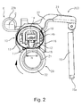
Figure 2 is a sectional view showing a part of a fixing device. -
Figure 3 is a perspective view showing the part of the fixing device. -
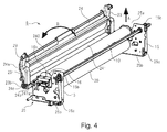
Figure 4 is a perspective view showing a state in which a cover of the fixing device is open. -
Figure 5 is a sectional view of the fixing device during pressing by a pressing arm. -
Figure 6 is a schematic view showing action of a force at a pressing position of the pressing arm. -
Figure 7 is a sectional view, of the fixing device, showing a state in which a pressing force of the abutment is released (eliminated). -
Figure 8 is a schematic view showing action of a force in the state in which the pressing force of the pressing arm is released. -
Figure 9 is a sectional view, of the fixing device, showing a non-released state of a releasing arm. -
Figure 10 is a sectional view, of the fixing device, showing an operation direction of the releasing arm. -
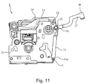
Figure 11 is a sectional view, of the fixing device, showing a released state of the releasing arm. -
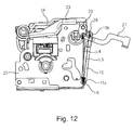
Figure 12 is a sectional view, of the fixing device, showing a state in which a pressing spring is demounted from the releasing arm. - An embodiment to which the present invention is applicable will be described with reference to
Figures 1 to 12 . First, a general structure of an image forming apparatus including a fixing device as an image heating apparatus, provided with a pressing mechanism, according to this embodiment will be described with reference toFigure 1 . - An
image forming apparatus 100 includes a photosensitive drum (photosensitive member) as an image bearing member as shown inFigure 1 . The photosensitive drum 1 is constituted by forming, on a cylindrical substrate of aluminum or nickel, a layer of photosensitive material such as an organic photoconductor (OPC), amorphous Se or amorphous Si. - The photosensitive drum 1 is rotationally driven in an arrow direction shown in
Figure 1 and at first, a surface thereof is electrically charged uniformly by acharging roller 2 as a charging means. Next, the photosensitive drum surface is subjected to scanning exposure to a laser beam α ON/OFF-controlled depending on image information by alaser scanner 3 as an exposure means, so that an electrostatic latent image is formed. This electrostatic latent image is developed and visualized by the developingdevice 4. As a developing method, a jumping developing method, a two-component developing method, a FEED developing method (contact developing method using a one-component insulating toner) or the like is used, and in many cases, image exposure and reverse development are used in combination. - The visualized toner image is transferred from the photosensitive drum 1 onto a recording material P fed at predetermined timing by a
transfer roller 5 as a transfer means. Here, a leading end of the recording material P is detected by a sensor 8 so that an image forming position of the toner image on the photosensitive drum 1 and a writing start position of the leading end of the recording material P coincide with each other, thus adjusting timing. - The recording material P fed at predetermined timing is nipped and fed at a certain pressing force (pressure) by the photosensitive drum 1 and the
transfer roller 5. The recording material P no which the toner image is transferred is fed into afixing device 6 as an image heating apparatus, so that the toner image is fixed as an image. - On the other hand, a transfer residual toner remaining on the photosensitive drum 1 is removed from the surface of the photosensitive drum 1 by a cleaning device 7. Further, in the
fixing device 6, a discharge sensor 9 for detecting the leading end of the recording material P is provided and detects paper jam when the recording material P causes the paper jam between the sensor 8 and the discharge sensor 9. - Next, with reference to
Figures 2 and3 , a general structure of thefixing device 6 as the image heating apparatus will be described. Thefixing device 6 includes afixing assembly 10 for heating the image carried on the recording material P, anopposite roller 20 as a rotatable member (nip-forming member) for forming a nip N where the recording material P is to be sandwiched between theopposite roller 20 and thefixing assembly 10, and apressing device 200 described specifically later. Thefixing assembly 10 is a unit for rotatably holding afixing film 13 as a rotatable member. - The
fixing assembly 10 is a member-to-be-pressed to be pressed by thepressing device 200 and includes thefixing film 13, a (heating)heater 11 as a heating mechanism, a heating-insulating holder 12 for holding theheater 11, and ametal stay 14. Here, themetal stay 14 receives a pressing (urging) force by a pressingspring 15 as an urging means via apressing arm 23 as an abutting member (pressing member) and aflange 16 to press the heat-insulating holder 12 toward theopposite roller 20. - The
heater 11 is a ceramic heater formed in a plate shape and generates heat by supply of electric power (energy). The heat-insulating holder 12 for holding theheater 11 is formed of a heat-resistant resin material such as a liquid crystal polymer, a phenolic resin, PPS (polyphenylene sulfide) or PEEK (polyether ether ketone). A degree of heat conduction to theopposite roller 20 is better with a decreasing thermal conductivity, and therefore a filler such as a glass balloon or a silica balloon may also be incorporated into a layer of the resin material. Further, the heat-insulating holder 12 also has the function of guiding rotation of thefixing film 13. The metal stay 14 contacts the heat-insulating holder 12, thus suppressing flexure and torsion of the fixing assembly as a whole. - The
fixing film 13 is a heat-resistant film having a total thickness of 200 µm or less in order to enable quick start of the image forming apparatus. Such afixing film 13 is prepared by forming a base layer of a heat-resistant resin material such as polyimide, polyamideimide, PEEK; or metal or alloy having a heat-resistance property and a high thermal conductivity, such as SUS (stainless steel), Al, Ni, Cu, Zn, or the like. - In the case of the resin-made base layer, in order to improve the thermal conductivity, high thermal conductivity powder of BN, alumina, Al or the like may also be mixed. Further, in order to constitute a long-lifetime fixing apparatus, as the
fixing film 13 which has a sufficient strength and which is excellent in durability, the total thickness may preferably be 20 µm or more. Accordingly, the total thickness of thefixing film 13 in the range of 20 µm or more and 200 µm or less is optimum. - Further, in order to ensure an offset preventing property and a recording material separating property, as a surface layer, a parting layer of a heat-resistant resin, having a good parting property, including a fluorine-containing resin such as PTFE, PFE, FEP, ETFE, CTFE or PDV; silicone resin; and the like. These resins are used singly or in mixture. In this embodiment, the surface (parting) layer is constituted by a material at least containing PTFE and PFA.
- Here, PTFE is polytetrafluoroethylene, PFA is tetrafluoroethylene-perfluoroalkylvinyl ether copolymer, FEF is tetrafluoroethylene-hexafluoropropylene copolymer, ETFE is ethylene-tetrafluoroethylene copolymer, CTFE is polychlorotrifluoroethylene, and PVDF is polyvinylidene fluoride.
- As a coating method, dipping of the parting layer after etching of the outer surface of the
fixing film 13, application such as powder spraying, a method in which the surface of thefixing film 13 is coated with a tube-like resin material, or a method in which the outer surface of thefixing film 13 is blasted and thereafter a primer layer of an adhesive is applied and then the parting layer is coated on the primer layer may be used. - The
opposite roller 20 is an elastic roller prepared by forming anelastic layer 22, such as an elastic solid layer, an elastic sponge rubber layer or an elastic foam rubber layer, outside acore metal 21 of SUS, SUM (sulfur or sulfur complex free-cutting steel material), Al or the like. Here, the elastic solid rubber layer is formed with a heat-resistant rubber such as a silicone rubber or a fluorine-containing rubber. The elastic sponge rubber layer is formed by foaming the silicone rubber in order to provide a further heat-insulating effect. Further, the elastic foam rubber layer is formed by dispersing a hollow filler (microballoon or the like) in a silicone rubber layer and by incorporating a gas component in a cured material to enhance the heat-insulating effect. On the surface of theelastic layer 22, a parting layer of perfluoroalkoxy resin (PFA), polytetrafluoroethylene resin (PTFE) or the like may also be formed. - The fixing
assembly 10 is pressed toward theopposite roller 20 against elasticity of theopposite roller 20 by thepressing device 200 described later to form the nip N. At the nip N, the fixingfilm 13 is sandwiched between theheater 11 and theopposite roller 20 by the pressing force to be flexed, thus being placed in a state in which the fixingfilm 13 closely contacts a heating surface of theheater 11. - The
opposite roller 20 obtains a driving force, for rotating in an arrow direction inFigure 2 , by adriving gear 17 provided at an end portion of thecore metal 21 as shown inFigure 3 . The driving force is transmitted by amotor 202 as a driving means in accordance with an instruction from a controller (CPU) 201 as a control means. Incidentally, thecontroller 201 is also used as a controller for theimage forming apparatus 100, but thefixing device 6 itself includes the controller. - With rotational drive of the
opposite roller 20, the fixingfilm 13 is rotated (moved) by a frictional force with theopposite roller 20. At this time, the fixingfilm 13 slides with theheater 11. Between the fixingfilm 13 and theheater 11, a lubricant such as heat-resistant grease of a fluorine-type or a silicone-type is disposed, so that a frictional resistance is suppressed to a low level and thus the fixingfilm 13 is smoothly rotatable (movable). - Further, temperature control of the
heater 11 is effected by determining, on the basis of a signal of a temperature detecting element such as a thermistor, a duty ratio or wave number or the like of a voltage, to be applied to an energization heat generating resistance layer of theheater 11, by thecontroller 201. Further, the temperature in the nip N is maintained at a desired fixing set temperature. Here, various thermistors used for the temperature control are athermistor 18 provided on a back surface of the ceramic substrate and athermistor 19 provided on an inner surface of the fixingfilm 13, for directly detecting the temperature of the fixingfilm 13. - Further, the
metal stay 14 is provided with a groundingmember 14a for the purpose of ensuring grounding with the fixingfilm 13. The groundingmember 14a and thethermistor 19 elastically slidably contact the inner surface of the fixingfilm 13 in a state in which the fixingfilm 13 is mounted. For this reason, the groundingmember 14a and thethermistor 19 are provided with a member, such as a metal plate, having a spring property and are mounted so that an end thereof is projected to an outside of a projected shape of the fixingfilm 13 during mounting of the fixingfilm 13 in a natural state while possessing the spring property. - As described above, the recording material P holding the (unfixed) toner image is nipped and fed at the nip N, so that the toner image is heat-fixed on the recording material P. The recording material P discharged from the nip N is guided by an unshown discharging guide to be discharged.
- Next, the
pressing device 200 for pressing the fixingassembly 10 as the member-to-be-pressed will be described with reference toFigures 2 to 5 . Thepressing device 200 includes acasing 25, anopenable cover 24 as a cover member, apressing arm 23 was a pressing member, and apressing spring 15 as a spring member (urging member). Thecasing 25 is a unit for rotatably holding theopposite roller 20 and is provided with anopening 25a for permitting mounting and demounting of the fixingassembly 10, theopposite roller 20 and the like. Such acasing 25 includes a pair of supportingplates 25b between which the fixingassembly 10 and theopposite roller 20 are accommodated and disposed and are supported at end portions thereof. - The
openable cover 24 is supported, by thecasing 25, rotatably relative to thecasing 25 between a shielding (closing) position (position ofFigure 5 ) where theopenable cover 24 covers theopening 25a of thecasing 25 and an open position (position ofFigure 4 ) where theopening 25a is open. Such anopenable cover 24 includes a coveringportion 240 for covering theopening 25a and abent portion 241 formed so as to be bent from a base end side of the coveringportion 240 toward thecasing 25 side. Further, arotation shaft 241a provided at an end portion of thebent portion 241 in an opposite side to the coveringportion 240 is rotatably supported by each of the pair of supportingplates 25b of thecasing 25. As a result, theopenable cover 24 is supported by the casing rotatably about a rotation center D (Figure 5 ). - The
pressing arm 23 is supported by theopenable cover 24 so as to be rotatable in one end side within a predetermined angle range. Further, thepressing arm 23 is also rotatable integrally with theopenable cover 24. Further, thepressing arm 23 is positioned at a pressing position (position ofFigure 5 ) where thepressing arm 23 is capable of applying the pressing force to the fixingassembly 10 at the shield position of theopenable cover 24. - In this embodiment, the
pressing arm 23 is rotatably by theopenable cover 24 at the base end portion thereof in one end side. For this reason, thepressing arm 23 is provided with a cylindricalrotatable portion 23b at the base end portion thereof, and the coveringportion 240 of theopenable cover 24 is provided with a rotation supporting portion (boss) 24c at each of base end-side end portions thereof. Further, therotatable portion 23b is rotatably engaged with therotation supporting portion 24c, so that thepressing arm 23 is held by theopenable cover 24 so as to be rotatable about a rotation center C (Figures 2 and5 ). - Further, the
openable cover 24 is provided with a first limitingportion 24a and a second limiting portion 24b which are used as a stopper (rotation stopping portion) for limiting relative rotation between thepressing arm 23 and the openable cover 24 (for limiting rotation in a distance exceeding the predetermined angle range). The first limitingportion 24a is formed, at each of end portions of the coveringportion 240 of theopenable cover 24, so as to cover thepressing arm 23 in a rotation side toward an open direction (arrow B direction inFigure 4 ) of thepressing arm 23. Further, in the case where thepressing arm 23 is rotated in the open direction, a part of thepressing arm 23 and the first limitingportion 24a contact each other, so that the first limitingportion 24a limits rotation of thepressing arm 23 in the open direction relative to theopenable cover 24. That is, with the rotation of thepressing arm 23 in the open direction, theopenable cover 24 is rotated in the open direction together with thepressing arm 23. - On the other hand, the second limiting portion 24b is projected, at a central portion of the
bent portion 241 of theopenable cover 24, so as to cover the base of thepressing arm 23 in a rotation side toward a shield direction (direction opposite to the arrow B direction inFigure 4 ) of thepressing arm 23. Further, in the case where thepressing arm 23 is rotated in the shield direction, a part of thepressing arm 23 and the second limiting portion 24b contact each other, so that the first limitingportion 24a limits rotation of thepressing arm 23 in the shield direction relative to theopenable cover 24. That is, with the rotation of thepressing arm 23 in the shield direction, theopenable cover 24 is rotated in the shield direction together with thepressing arm 23. - In the case of this embodiment, by providing a gap between the
pressing arm 23 and each of the first and second limitingportions 24a and 24b, theopenable cover 24 and thepressing arm 23 are somewhat rotatable relative to each other. Incidentally, such a rotation stopping portion for limiting the relative rotation can also have another constitution such that, e.g., thepressing arm 23 is supported by theopenable cover 24 in a non-rotatable manner (or in a somewhat rotatable manner). - The
pressing spring 15 is fixed to thepressing arm 23 at one end thereof and is fixed to thecasing 25 at another end thereof, and urges thepressing arm 25 in an application direction (pressing direction) of a pressing force (urging force). In this embodiment, thepressing spring 15 is a tension spring connected, at one end portion thereof, with an engaginghole 25c as a casing-side connecting portion provided in thecasing 25 and, at another end portion thereof, with a projected portion (boss) 29 as a rotatable portion-side connecting portion in thepressing arm 23 side. In this embodiment, thepressing spring 15 is coil spring. That is, a one end portion-side hooking portion 15a formed at the one end portion of thepressing spring 15 is hooked in theengaging hole 25a of thecasing 25, and another end portion-side hooking portion 15b formed in a ring (loop) shape at another end portion of thepressing spring 15 is hooked on the projectedportion 29. Thus, thepressing spring 15 is disposed, between the engaginghole 25c and the projectedportion 29, in a state in which thepressing spring 15 is elastically elongated from a free state, so that thepressing arm 23 is urged in the pressing direction. Incidentally, the projectedportion 29 constitutes a releasing (eliminating)mechanism 205 as a releasing (eliminating) means as described later, and is provided in a projected manner on a releasingarm 27 as an arm member rotatably supported at a supportingportion 28 by thepressing arm 23. Further, the projectedportion 29 is disposed at a position closer to a free end (portion W shown inFigure 11 ), as an end of the releasingarm 27 with respect to an extension direction, than the supportingportion 28 of the releasingarm 27. Further, at the free end portion W of the releasingarm 27, a grip portion is provided. - Further, the
pressing arm 23 can be freely connected with and demounted from another end portion of thepressing spring 15 connected with thecasing 25 at the one end portion of the pressing spring. That is, the another end portion-side hooking portion 15b of thepressing spring 15 is pulled off from the projectedportion 29 in thepressing arm 23 side, so that thepressing arm 23 can be demounted from another end portion of thepressing spring 15. Further, by inserting the projectedportion 29 into the another end portion-side hooking portion 15b, thepressing arm 23 can be connected another end portion of thepressing spring 15. Incidentally, such connection and demounting between thepressing spring 15 and thepressing arm 23 can be performed by using a tool such as a plier even in a state in which thepressing spring 15 is pressed. However, in this embodiment, as described later, the connection and the demounting are performed in a state in which the pressing force by thepressing spring 15 is released (eliminated) or reduced. - The fixing assembly O is supported at each of end portions thereof by a
flange 16. That is, anarcuate guiding portion 16a formed so as to be projected from an inside surface of theflange 16 is inserted into the fixingfilm 13 from the end portion of the fixingfilm 13, so that the fixing 13 is rotatably supported by the guidingportion 16a provided on theflange 16 at each of the end portions thereof. Theseflanges 16 provided at the end portions are connected by themetal stay 14. Accordingly, by theflanges 16 provided at the end portions, themetal stay 14, the heat-insulatingholder 12 supported by themetal stay 14, theheater 11 held by the heat-insulatingholder 12, and the like are supported. Further, theflanges 16 provided at the end portions are detachably mounted to the pair of supporting plates of thecasing 25 and are mounted so as to be freely movable toward and away from theopposite roller 20. Further, on each of outside surfaces of theflanges 16 provided at the end portions, acontact receiving portion 16b contactable with thepressing arm 23 at the pressing position is provided in a projected manner. - The thus-constituted
pressing device 200 applies the pressing force to the fixingassembly 10 via theflanges 16 by the contact of thepressing arm 23 with thecontact receiving portion 16b of theflange 16. That is, thepressing spring 15 is connected with thecasing 25 at one end portion thereof and is connected with thepressing arm 23 at another end portion thereof. Further, thepressing arm 23 is held rotatably about the rotation center C and is urged by thepressing spring 15 at one end portion thereof, so that thepressing arm 23 contacts thecontact receiving portion 16b of theflange 16 at the pressing position. Further, thepressing arm 23 applies the urging force to theflange 16, thus pressing theflange 16 toward theopposite roller 20. The urging force transmitted to theflanges 16 acts on the end portions of themetal stay 14, and as a result thereof, themetal stay 14 is pressed toward theopposite roller 20. As a result, the heat-insulatingholder 12 disposed in contact with themetal stay 14 and theheater 11 disposed in contact with the heat-insulatingholder 12 are integrally pressed toward the urging 20. - Here, as shown in
Figure 3 , themetal stay 14 is projected from the heat-insulatingholder 12 at longitudinal end portions thereof and is inserted into theflanges 16, so that thepressing arms 23 disposed on theflanges 16 are pressed by the pressing springs. As a result, a load by thepressing spring 15 is uniformly transmitted over the longitudinal direction of the heat-insulatingholder 12 via astay foot portion 14b contacting the heat-insulatingholder 12 of themetal stay 14. In this way, themetal stay 14, the heat-insulatingholder 12 and theheater 11 are pressed by thepressing springs 15, so that the fixingfilm 13 is sandwiched between theopposite roller 20 and a structure including the heat-insulatingholder 12 and theheater 11 to form the nip N. - Next, with reference to
Figures 4 and5 , a constitution for mounting and demounting the fixingassembly 10 with respect to thecasing 25 will be described. The fixingassembly 10 is detachably mounted to thecasing 25 in an arrow A direction inFigure 4 through theopening 25a provided in thecasing 25. To thecasing 25, theopenable cover 24 is rotatably mounted, and theopenable cover 24 is rotated in an arrow B direction ofFigure 4 , so that theopening 25a of thecasing 25 is exposed (opened) to place the fixingassembly 10 in a detachably mountable state. - Here, the
pressing arm 23 for pressing the fixingassembly 10 toward theopposite roller 20 is rotatably supported by therotation supporting portion 24c provided on theopenable cover 24. Further, by disconnecting thepressing spring 15 connected to another end portion of thepressing arm 23, thepressing arm 23 is rotatable to the open position integrally with theopenable cover 23. In other words, thepressing arm 23 and theopenable cover 24 are capable of being retracted from a locus with respect to a demounting direction of the fixingassembly 10 when the fixingassembly 10 is demounted in the arrow A direction. That is, thepressing arm 23 is demounted from another end portion of thepressing spring 15 and then is rotated in an arrow C direction about the rotation center C. Then, thepressing arm 23 contacts the first limitingportion 24a of theopenable cover 24, so that theopenable cover 24 is rotated together with thepressing arm 23 in the arrow B direction, i.e., the open direction. As a result, theopening 25a is exposed, so that the fixing assembly is detachably mountable. - On the other hand, during use of the fixing
device 6, in a state in which the fixingassembly 10 is mounted in thecasing 25, theopenable cover 24 is rotated in a direction opposite to the arrow B direction to cover theopening 25a. At this time, thepressing arm 23 is rotated together with theopenable cover 24 by the second limiting portion 24b in the direction opposite to the arrow B direction, so that theopenable cover 24 is positioned at the shield position. At this position, thepressing spring 15 is connected with the end of thepressing arm 23 to place thepressing arm 23 at the pressing position as shown inFigure 5 , so that a force from thepressing spring 15 is transmitted to the fixingassembly 10 via thepressing arm 23 to press the fixingassembly 10 toward theopposite roller 20. Further, theopenable cover 24 is fixed at the shield position in a state in which thepressing arm 23 is connected with thepressing spring 15 as described above. - Next, with reference to
Figures 5 and6 , a mechanism for fixing thecontact 24 at the shield position (i.e., a mechanism in which theopenable cover 24 is maintained at the shield position without using the lock mechanism as used in the conventional constitution) will be described.Figure 6 schematically shows a force acting on thepressing arm 23 and theopenable cover 24. First, as shown inFigure 6 , in a state in which an urging force G1 by thepressing spring 15 acts on thepressing arm 23, a contact portion (point) between thepressing arm 23 and thecontact receiving portion 16b of theflange 16 is taken as point E. Further, a force acting from thepressing arm 23 onto theopenable cover 24 with the point E as a fulcrum by the urging force G1 is taken as G2. At this time, a position of the rotation center D of theopenable cover 24 is set to that moment H in a direction toward the shield position is applied to theopenable cover 24 by the force G2 with, as a center, the rotation center relative to thecasing 25. - For this reason, in the case of this embodiment, the position of the rotation center D of the
openable cover 24 is set so as to satisfy the following condition. First, a point where the urging force G1 acts from thepressing arm 23 onto theopenable cover 24 with the point E as the fulcrum is taken as application point F. In this case, the rotation center D of theopenable cover 24 is positioned relative to theopenable cover 24 in an acting direction of the urging force G1 and is also positioned in the fulcrum side (point E side) with respect to the application point F. In other words, the rotation center D is positioned in the shield position side (lower side inFigure 6 ) than theopenable cover 24 and is disposed between the application point F and the point E. This will be specifically described below. - In general, during operation of the image forming apparatus, in order to form the nip N, in the
fixing device 6, the urging force from thepressing spring 15 is transmitted to the fixingassembly 10, so that the fixingassembly 10 is press-contacted to theopposite roller 20. At this time, the urging force of thepressing spring 15 acts on one end of thepressing arm 23 to apply moment about the rotation center C to thepressing arm 23. The moment applied to thepressing arm 23 is transmitted as an urging force for urging (pressing) theflange 16, contacting thepressing arm 23 at the point E, toward theopposite roller 20, and as a result, the fixingassembly 10 is pressed toward theroller 20. - Further, the
pressing arm 23 is rotatably connected with theopenable cover 24. For this reason, when the point E as the contact point between thepressing arm 23 and theflange 16 is the fulcrum and the connecting portion (point) with thepressing spring 15 is a force application point (power point), at a point F as a contact portion (point) between theopenable cover 24 and thepressing arm 23, the urging force corresponding to the application point in the principle of leverage is generated. At this time, a relationship between forces exerted on respective portions is as shown inFigure 6 . - That is, the
pressing arm 23 is connected with thepressing spring 15 at one end of thereof and is connected with theopenable cover 24 at another end thereof. When the urging force G1 is applied to thepressing arm 23 in the arrow direction inFigure 6 by thepressing spring 15, thepressing arm 23 applies the urging force G2 in the arrow direction inFigure 6 to the application point F on theopenable cover 24 with the point E as the fulcrum. Theopenable cover 24 is rotatably supported about the rotation center D by thecasing 25, and therefore the urging force G2 applied to theopenable cover 24 is replaced with moment G3 and normal reaction G4, shown by the arrows inFigure 6 , acting on theopenable cover 24. Theopenable cover 24 has the constitution in which theopenable cover 24 is rotatable about the rotation center D, so that by the moment G3, moment (rotational force) H in the arrow direction inFigure 6 acts on theopenable cover 24. By the action of this force, theopenable cover 24 is urged in a direction (toward the shield position) in which theopenable cover 24 covers theopening 25a of thecasing 25 only by connecting thepressing spring 15 with thepressing arm 23. As a result, theopenable cover 24 can be maintained at the shield position without separately using a fastening mechanism or a lock mechanism which are used for fastening theopenable cover 24 to thecasing 25. - Next, with reference to
Figures 7 and8 , a pressing (force) adjustingmechanism 203 as a means (spacing mechanism) for adjusting the pressing force to be applied to the fixingassembly 10 will be described. Thepressing adjusting mechanism 203 adjusts the pressing force to be applied to the fixingassembly 10 by moving thepressing arm 23 positioned at the pressing position in a direction opposite to the pressing force application direction. For this purpose, thepressing adjusting mechanism 203 includes an adjustingcam 26 as a contact member for moving thepressing arm 23 in contact with thepressing arm 23, and amotor 204 as a driving means for rotationally driving the adjustingcam 26. - The adjusting
cam 26 has an outer peripheral surface having different distances from the rotation center thereof, and changes the position of the outer peripheral surface contacting thepressing arm 23, so that the adjusting can 26 moves thepressing arm 23. Specifically, the adjustingcam 26 is rotatably supported by thecasing 25, in the neighborhood of the end of thepressing arm 23, at a position of the end in the urging direction side of thepressing spring 15. Further the adjustingcam 26 is constituted so as to have an outer configuration as an eccentric surface with respect to the rotation center. Further, depending on a phase, the adjustingcam 26 retracted to a non-contact position with thepressing arm 23 positioned in the pressing position, and contacts and presses thepressing arm 23 to move thepressing arm 23 in a direction in which thepressing arm 23 moves against the urging force of thepressing spring 15. Such rotation of the adjustingcam 26 is controlled by driving themotor 204 by an instruction from thecontroller 201, so that it is possible to set the phase of the adjustingcam 26 at an arbitrary position. - In this way, the adjusting
cam 26 contacts thepressing arm 23 to push up thepressing arm 23 in an arrow direction inFigure 7 , so that the pressing force applied to the fixingassembly 10 is released (eliminated) or alleviated by thepressing arm 23. That is, the phase of the adjustingcam 26 is set at the position as shown inFigure 7 , thepressing arm 23 is spaced from thecontact receiving portion 16b of theflange 16, so that the pressing force applied from thepressing arm 23 to the fixingassembly 10 is released or removed. Incidentally, even in a state in which thepressing arm 23 contacts thecontact receiving portion 16b, the pressing force by thepressing arm 23 may also be alleviated by moving thepressing arm 23 from the above-described pressing position shown inFigure 5 . That is thepressing arm 23 pushed up by thecam 26 is spaced from at least a part of theflange 16. - Specifically, e.g., during non-operation of the image forming apparatus, in general, in order to prevent the
elastic layer 22 of theopposite roller 22 from causing distortion by the pressing force from the fixingassembly 10, the nip N is not formed or a minute nip is formed under application of small pressure. For this purpose, in this embodiment, the phase of the adjustingcam 26 is adjusted at a predetermined phase so as to displace thepressing arm 23 in the arrow direction inFigure 7 by causing the adjustingcam 26 to contact and press thepressing arm 23. As a result, the fixingassembly 10 is prevented from press-contacting theopposite roller 20 by the urging force from thepressing spring 15 or is press-contacted to the opposite roller 20at low pressure. At this time, the urging force of thepressing spring 15 acts on one end of thepressing arm 23 to apply moment about the rotation center C of thepressing arm 23. The moment applied to thepressing arm 23 is transmitted to the outer (configuration) surface of the adjustingcam 26 contacting thepressing arm 23 at a point J, so that the urging force to be transmitted to the fixingassembly 10 is blocked or alleviated. As a result, the fixingassembly 10 is not pressed in the direction of theopposite roller 20 or is pressed toward theopposite roller 20 at small pressure. - On the other hand, during the operation of the image forming apparatus, in general, the fixing
device 6 forms the nip N, and in order to fix the toner image on the recording material, the phase of the adjustingcam 26 is adjusted at the position where the adjustingcam 26 is retracted from the pressing arm 23 (Figure 5 ). As a result, the urging force from thepressing spring 15 is transmitted to the fixingassembly 10, so that the fixingassembly 10 is press-contacted to theopposite roller 20 to form the nip N, and thus it becomes possible to apply heat and pressure onto the - recording material passing through the nip N.
- Further, when the type of the recording material to be passed through the nip N is changed, a width of the nip N (with respect to the recording material feeding direction) in some cases. For example, in the case of the thin paper, the width of the nip N is decreased to reduce the heat quantity to be applied, and in the case of thick paper, the width of the nip N is increased to increase the heat quantity to be applied. Even in such cases, the pressing force applied to the fixing
assembly 10 is changed by changing the phase of the adjustingcam 26, so that it is possible to properly adjust the width of the nip N. - Here, the mechanism for fixing the
openable cover 24 at the shield position in the state in which thepressing arm 23 is positioned at the pressing position was described above. On the other hand, as described above, even in the case where the pressing force from thepressing arm 23 is released or alleviated by thepressing adjusting mechanism 203, theopenable cover 24 may preferably be fixed at the shield position. - For this purpose, in this embodiment, a
surface 23a, of thepressing arm 23, contacting the adjustingcam 26 is tilted so as to satisfy the following condition. As shown inFigures 7 and8 , the contact position between the adjustingcam 26 and thepressing arm 23 is the point J, and the application point where the force from thepressing arm 23 acts on theopenable cover 24 on the basis of the urging force G1 applied from thepressing spring 15 to thepressing arm 23 is the point F. Further, a rectilinear line passing through the points J and F is taken as a phantom line L. At this time, the phantom line L corresponds to a dynamically phantom arm. Further, on the basis of the urging force G1, reaction force received by thepressing arm 23 at the point J is G5, and reaction force received by theopenable cover 24 at the application point F is G8. In this case, theabove surface 23a is tilted relative to the phantom line L so that the moment H rotated toward the shield position about the rotation center D relative to thecasing 25 is applied to theopenable cover 24 by the resultant of the reaction forces G5 and G8 on the basis of the urging force G1. - In this embodiment, the
pressing arm 23 is formed so that thesurface 23a contacting the adjustingcam 26 is tilted, in the urging direction by thepressing spring 15, toward another end side (end side, i.e., the connecting portion side with the pressing 15). As a result, thesurface 23a has an angle non-parallel to the phantom line L, so that the normal reaction received from the adjustingcam 26 at the point J generates moment, via thepressing arm 23, in the closing direction of theopenable cover 24. This will be described specifically below with reference toFigure 8 . Incidentally, in the following description, in the case where moment magnitudes (values) are compared, comparison will be made in terms of an absolute value. - When the urging force G1 is applied to the
pressing arm 23 in the arrow direction inFigure 8 by thepressing spring 15, moment with the point J, as the fulcrum, which is the contact position between thepressing arm 23 and the adjustingcam 26 is applied to thepressing arm 23. At this time, thepressing arm 23 receives the normal reaction (reaction force) G5, from the adjustingcam 26 at the point J, directed in the arrow direction inFigure 8 . Here, with respect to the phantom line L connecting the point J and the application point F where the force acts from thepressing arm 23 onto theopenable cover 24 with the point J as the fulcrum, the normal reaction G5 has an angle which is not the right angle. For this reason, the normal reaction G5 can be replaced with a force G6 perpendicular to the phantom line L and a force G7 parallel to the phantom line L. Of these two forces G6 and G7, the force G7 which is a parallel component with the phantom line L is a force for pulling in thepressing arm 23 in the G7 direction along the phantom line L. Thepressing arm 23 is connected with theopenable cover 24 at the point F, and therefore thepressing arm 23 is pulled in by a force G7 in the direction of the phantom line L, whereby moment acts on theopenable cover 24 in the arrow D inFigure 8 (which the same direction as the direction of the moment H) with the rotation center D as the center. - On the other hand, when the urging force G1 is applied to the
pressing arm 23 in the arrow direction inFigure 8 by thepressing spring 15, thepressing arm 23 applies an urging force G8 to the application point F on theopenable cover 24 in the arrow direction inFigure 8 with the point J as the fulcrum. Theopenable cover 24 is supported by thecasing 25 rotatably about the rotation center D, and therefore the urging force G8 to theopenable cover 24 is replaced with normal reaction G9 to theopenable cover 24 and moment G10 directed in the arrow direction inFigure 8 . Theopenable cover 24 is constituted so as to be rotatable about the rotation center D, and therefore by the moment G10, moment directed in a direction opposite to the direction of the moment H indicated by the arrow inFigure 8 acts on theopenable cover 24. - Here, as described above, when the moment by the force G7 acting on the point J is larger than the moment G10 acting on the point F, the moment H directed in the arrow direction in
Figure 8 acts on theopenable cover 24. In other words, by the resultant of the reaction force G5 at the point J and the reaction force G8 at the point F, the moment H is applied to theopenable cover 24 in the direction in which theopenable cover 24 is moved toward the shield position relative to thecasing 25 with the rotation center D as the center. Accordingly, in this embodiment, by properly setting the position of the rotation center D and the tilt angle of thesurface 23a of thepressing arm 23, the moment by the force G7 acting on the joint J is made larger than the moment G10 acting on the point F. As a result, the moment H acts on theopenable cover 24, so that theopenable cover 24 is fixed at the shield position. - In the case of this embodiment described above, even in the state in which the pressing force of the
pressing arm 23 is released or alleviated, theopenable cover 24 is urged in the direction of covering theopening 25a of thecasing 25 only by connecting thepressing spring 15 with thepressing arm 23. Accordingly, in the case of this embodiment, irrespective of the operation of thepressing adjusting mechanism 203 and without separately using the fastening means for fastening theopenable cover 24 to thecasing 25, it is possible to fix theopenable cover 24 at the shield position. - Incidentally, in the case of this embodiment, the moment G10 acting on the point F is opposite from the moment H for urging the
openable cover 24 toward the shield position. This is because the rotation center D of theopenable cover 24 relative to thecasing 25 is disposed outside the fixingdevice 6 to the possible extent. That is, inside the fixingdevice 6, various members such as the fixingassembly 10 are disposed, and when the rotation center D is disposed in a central side of the fixingdevice 6, there is a possibility that a degree of freedom of design is lowered. On the other hand, by disposing the rotation center D outside the fixingdevice 6 to the possible extent, the influence of the rotatable portion of theopenable cover 24 on arrangement of the various members in thefixing device 6 can be reduced, so that the degree of freedom of design is improved. On the other hand, when such a constitution is employed, the moment G10 acting on the point F acts in the opposite direction to the direction of the moment H as described above. However, in the case of this embodiment, by properly setting the tilt angle of thesurface 23a of thepressing arm 23, the moment by the force G7 acting on the point J is made larger than the moment G10, with the result that the force for fixing theopenable cover 24 at the shield position is provided. - By moving the rotation center D of the
openable cover 24 relative to thecasing 25 to a position in the point J side more than the position ofFigure 8 , the moment G10 acting on the point F may also be directed in the same direction as the direction of the moment H. In this case, there is no need to make the moment by the force G7 acting on the point J larger than the moment G10, and therefore the tilt angle of thesurface 23a, of thepressing arm 23, contacting the adjustingcam 26 with respect to the phantom line L can be made gentle. For this reason, the degree of freedom of the design of thepressing arm 23 is improved. Further, when the moment by the force G7 acting on the point J is smaller than the moment G10, the direction of the moment by the force G7 may also be opposite to the direction of the moment H. - Next, the releasing
mechanism 205 as the releasing means for releasing the urging force by thepressing spring 15 will be described with reference toFigures 9 and12 . The releasingmechanism 205 includes a releasingarm 27 as a rotatable portion rotatably supported by thepressing arm 23 and a projected portion (boss) 29 as a rotation-side connecting portion which is provided at a position out of a rotation center Q of the releasingarm 27 and with which thepressing spring 15 is connected. Further, on the basis of a rotational position of the releasingarm 27, the position of the projectedportion 29 is set so that thepressing arm 23 can be pressed by the urging force of thepressing spring 15 and so that the urging force of thepressing spring 15 can be alleviated or released. That is, in the case where the releasingarm 27 is positioned at the pressing position shown inFigure 9 , thepressing arm 23 is pressed by the urging force of thepressing spring 15 via the releasingarm 27. On the other hand, as shown inFigures 11 or12 , in the case where the releasingarm 27 is positioned at a releasing position where the releasingarm 27 is rotated from the pressing position by a predetermined angle, compared with the case where the releasingarm 27 is positioned at the pressing position, the urging force of thepressing spring 15 is alleviated or released. This will be described specifically below. - At another end of the
pressing arm 23, the base end portion of the releasingarm 27 is connected rotatably relative to thepressing arm 23 about a rotation shaft (supporting portion) 28. The releasingarm 27 is provided with the projectedportion 29, for connecting thepressing spring 15, at a position out of therotation shaft 28, and thepressing spring 15 and the releasingarm 27 are connected with each other by hooking another end-side hooking portion 15b, provided at another end portion of thepressing spring 15, on the projectedportion 29. Further, by hooking one end-side hooking portion 15a, provided at one end portion of thepressing spring 15, in the engaginghole 25c provided in thecasing 25, thepressing spring 15 and thecasing 25 are connected with each other at a connecting portion K. As a result, the urging force of thepressing spring 15 is applied to thepressing arm 23 via the releasingarm 27. - Further, the projected
portion 29 of the releasingarm 27 is provided at the position out of the rotation center Q of therotation shaft 28, so that a distance between the projectedportion 29 and the connecting portion K is changed by rotating the releasingarm 27 about therotation shaft 28. That is, by rotating the releasingarm 27 in an arrow M1 direction (releasing direction) ofFigure 9 , the projectedportion 29 is rotated and displaced about therotation shaft 28. Incidentally, at a free end W of the releasingarm 27, agrip portion 27a for operating the releasingarm 27 during a releasing operation is provided. - Then, the distance between the projected
portion 29 and the connecting portion K is decreased by the rotation of the releasingarm 27, so that another end-side hooking portion 15b of thepressing spring 15 is demountable from the projectedportion 29 at the releasing position where the distance is equal to the natural length of the pressing spring 15 (or is less than the natural length). In other words, in the case of this embodiment, the position of the projectedportion 29 is set so that the distance between the projectedportion 29 and the connecting portion K (engaginghole 25c) is the natural length of the pressing 15 at the releasing position of the releasingarm 27. - At such a releasing position, by disconnecting the
pressing spring 15 connected with the projectedportion 29, theopenable cover 24, thepressing arm 23 and the releasingarm 27 are integrally rotatable about the rotation center develop. Then, as described above, the fixingassembly 10 is mountable. - On the other hand, by rotating the releasing
arm 27 in an arrow M2 direction (non-releasing direction) ofFigure 10 , the distance between the projectedportion 29 and the connecting portion K is made larger than the natural length of thepressing spring 15, so that the urging force of thepressing spring 15 is applicable. At this time, the rotation of the releasingarm 27 is limited by abutment of anend contact portion 27b against abottom plate portion 23c of the releasingarm 23 as indicated by a broken line inFigure 9 . That is, thecontact portion 27b contacts thebottom plate portion 23c, so that further rotation of the releasingarm 27 relative to thepressing arm 23 in the arrow M2 direction is limited. Moreover, in this state, the urging force of the pressing 15 acts on thephotosensitive drum 29, so that moment directed in the arrow M2 direction is exerted on the releasingarm 27 and thus thecontact portion 27b contacts thebottom plate portion 23c with reliability. As a result, the releasingarm 27 is fixed to thepressing arm 23. - Next, the forces acting on the respective portions by the operation of the releasing
arm 27 will be described more specifically. In this embodiment, each of the above-described connecting portion K, the projectedportion 29 and therotation shaft 28 is set to satisfy the following conditions. First, as described above, the releasingarm 27 is mounted to thepressing arm 23 rotatably about therotation shaft 28 so that the releasingarm 27 is capable of being rotated and displaced along a locus shown inFigures 9 to 12 .Figure 9 shows a state in which the releasingarm 27 is placed in the non-releasing state (set state of the pressing spring 15). In this state, the phantom line (rectilinear line) L connecting the center of the projectedportion 29, connected with thepressing spring 15 provided on the releasingarm 27, with the connecting portion K of thepressing spring 15 with thecasing 25 is positioned in the non-releasing direction relative to therotation shaft 28 of the releasingarm 27. Further, by the urging force of thepressing spring 15, moment for urging the releasingarm 27 toward the non-releasing position (set position or a predetermined position of the pressing 15) is provided. - Here, a distance L2 between the center (rotation center Q) of the
rotation shaft 28 of the releasingarm 27 and the center of the projectedportion 29 and a distance L3 between the center of therotation shaft 28 and thegrip portion 27a are set so that a sufficient lever ratio, e.g., such that L3 is 5 times L2 is provided. As a result, even when the releasingarm 27 is urged to the non-releasing position by the urging force (e.g., 300N) of the pressing 15, by using the principle of leverage, the releasingarm 27 can be rotated in the releasing direction against the urging force only by a force multiplied by the reciprocal (inverse) of the lever ratio (e.g., 5). - When the releasing
arm 27 is rotated to the position ofFigure 10 in the releasing direction, the phantom line L connecting the center of the projectedportion 29 with the connecting portion K passes through the center of therotation shaft 28, and in this state, the moment for urging the releasingarm 27 toward the non-releasing position disappears. From this position as a turning point (position), when the releasingarm 27 is rotated toward the non-releasing position, moment for urging the releasingarm 27 toward the non-releasing position is applied to the releasingarm 27 by thepressing spring 15. On the other hand, when the releasingarm 27 is rotated from the above position toward the releasing direction, moment for urging the releasingarm 27 toward the releasing position is applied to the releasingarm 27 by thepressing spring 15. - Further, when the releasing
arm 27 is rotated to the position ofFigure 11 in the releasing direction, the distance between the projectedportion 29 and the connecting portion K is equal to the natural length of thepressing spring 15, so that in this state, the pressing force of thepressing spring 15 disappears. For this reason, thepressing spring 15 is easily demountable from the projectedportion 29. - Further, when the releasing
arm 27 is rotated to the position ofFigure 12 , the distance between the projectedportion 29 and the connecting portion K is smallest, and a distance L4 at that time is set to be shorter than a natural length L5 of thepressing spring 15. As a result, even when the distance L4 between the projected portion 2P and the connecting portion K fluctuates due to shape variation in parts and mounting accuracy, the distance L4 can be made shorter than the natural length L5 with reliability. Further, thepressing spring 15 is always in a non-load state, so that setting is made so that a demounting operation of thepressing spring 15 can be reliably performed with no load. - In the case of this embodiment, the position of
Figure 11 may be the releasing position, but in consideration of part accuracy or the like, the position ofFigure 12 may preferably be the releasing position. That is, an angle obtained by rotating the releasingarm 27 from the non-releasing position (predetermined position) ofFigure 9 to the position ofFigure 12 may preferably be taken as a predetermined angle providing the non-releasing position. - Incidentally, in the case where the
pressing spring 15 is demounted from the projectedportion 29, it is preferable that the urging force of thepressing spring 15 disappears. However, when the urging force of thepressing spring 15 is alleviated compared with the case where the releasingarm 27 is positioned at the predetermined position, the demounting of thepressing spring 15 becomes easy to some extent, and therefore the above-described predetermined angle can also be set at a position where the urging force of thepressing spring 15 does not disappear. - Further, in the above description, the rotation of the
pressing arm 23 and theopenable cover 24 is enabled by the disconnecting the another end-side hooking portion 15b of thepressing spring 15 from the projectedportion 29. However, e.g., at the releasing position, the releasingarm 27 is made separable from thepressing arm 23, so that the releasingarm 27 and thepressing spring 15 are disconnected from thepressing arm 23 and thus the rotation of thepressing arm 23 and theopenable cover 24 may also be enabled. In this case, it is possible to demount thepressing spring 15 from thepressing arm 23 while mounting thepressing spring 15 to be releasingarm 27. - Further, the
pressing spring 15 may also be constituted so as to be demounted from thecasing 25. That is, in a state in which thepressing spring 15 and thepressing arm 23 are connected with each other as they are, the one end-side hooking portion of thepressing spring 15 is demounted from thecasing 25. In such a constitution, the urging force of thepressing spring 15 is alleviated or released, and therefore the demounting of thepressing spring 15 can be easily performed. - According to the thus-constituted this embodiment, it is possible to easily perform an exchange operation of the fixing
assembly 10 by connecting thepressing arm 23 with thepressing spring 15 or by demounting thepressing arm 23 from thepressing spring 15. That is, theopenable cover 24 is fixed at the shield position in the state in which thepressing arm 23 is connected with the pressing 15, and is rotatable to the open position in the state in which thepressing arm 23 is demounted from thepressing spring 15. For this reason, in the case where the fixingassembly 10 is taken out from thecasing 25, theopenable cover 24 can be rotated to the open position by demounting thepressing arm 23 from thepressing spring 15. At this time, also thepressing arm 23 is rotated together with theopenable cover 24, and therefore only by operating either one of these members, thepressing arm 23 and theopenable cover 24 are retracted from a locus of the fixingassembly 10 with respect to the demounting direction, so that the fixingassembly 10 can be easily taken out from thecasing 25. - In summary, in the case of this embodiment, when the exchange operation of the fixing
assembly 10, theopposite roller 20 or the like is performed, only by connection releasing thepressing spring 15 from thepressing arm 23, the moment for urging and fixing theopenable cover 24 is eliminated or removed. For this reason, only by rotating theopenable cover 24 to open, thepressing arm 23 rotatably connected with theopenable cover 24 is retracted substantially integrally with theopenable cover 24 from the locus of the fixingassembly 10 with respect to the demounting direction. Then, theopening 25a of thecasing 25 is exposed, so that it becomes possible to perform mounting and demounting of the fixing assembly with respect to thefixing device 6 without performing the demounting of parts from the fixingdevice 6. - On the other hand, after the fixing
assembly 10 is placed in thecasing 25, theopenable cover 24 is rotated together with thepressing arm 23 to the shield position, where thepressing arm 23 is connected with thepressing spring 15, so that theopenable cover 24 is fixed. For this reason, without separately using the fastening means for fastening theopenable cover 25, theopenable cover 24 can be fixed at the shield position. As a result, also the mounting of the fixingassembly 10 into thecasing 25 can be easily performed. Also the exchange operation of theopposite roller 20 can be easily performed similarly together with the fixingassembly 10. - Further, in the case of this embodiment, the
pressing adjusting mechanism 203 for adjusting the pressing force by moving thepressing arm 23 is provided, and therefore even in the above-described constitution, the urging force for urging the fixingassembly 10 toward theopposite roller 20 is adjustable. As a result, during the non-operation of the fixingdevice 6, it is possible to suppress generation of distortion of theelastic layer 22 of theopposite roller 22 caused by the urging force from the fixingassembly 10. Further, depending on the type of the recording material and the like, the width of the nip N can be properly adjusted. - Further, in the case of this embodiment, by rotating the releasing
arm 27, the urging force of thepressing spring 15 can be alleviated or released, and therefore the demounting of thepressing spring 15 from thepressing arm 23 can be easily performed by operating the releasingarm 27. As a result, in the case where the exchange operation of the fixingassembly 10 and theopposite roller 20 is performed, it becomes possible to simply demount (connection-release) thepressing spring 15 from thepressing arm 23 without using a tool or the like. - As described above, in this embodiment, when the exchange operation of the fixing
assembly 10 or the like is performed, an opening and closing operation of theopenable cover 24 can be easily performed. Particularly, there is no need to perform a mounting and demounting operation of parts such as a fastening means for fastening theopenable cover 24. Further, there is no need to use the tool for performing the mounting and demounting of thepressing spring 15. For this reason, a time required for the exchange operation can be shortened, and therefore a downtime of the image forming apparatus can be shortened, so that convenience is improved. Further, the exchange operation becomes easy, and therefore mounting of the parts can be performed with high accuracy. - In the above-described embodiment, as the fixing device, the constitution of a combination of the fixing film with the opposite roller was described, but the present invention is not limited thereto. For example, as the rotatable member constituting the fixing device, even when a fixing roller including therein a heater or a heating belt to be heated by electromagnetic induction heating is used, the present invention is similarly applicable.
- Further, as the member demounted from and mounted in the casing, not only the fixing film (fixing assembly) but also the opposite roller may be used.
- Further, either one of the fixing film and the opposite roller may only be required to be pressed toward another one of the members.
- Further, as the urging means, a constitution other than the tension spring described above may also be employed. For example, a compression spring for urging the pressing member by an elastically restoring force directed from an elastically compressed state to an extension direction may also be employed.
- Further, the pressing adjusting means may also have a constitution other than the constitution using the cam as described above if the pressing member is moved in the constitution. For example, by using a rack and a pinion, the rotational force of the motor is converted into a force directed in a linear direction, so that the pressing member may also be moved by this linear direction force.
- While the invention has been described with reference to the structures disclosed herein, it is not confined to the details set forth and this application is intended to cover such modifications or changes as may come within the purpose of the improvements or the scope of the following claims.
- An image heating apparatus includes: (i) first and second rotatable members for forming a nip for heating of a toner image on a sheet; (ii) a first unit for rotatably holding the first rotatable member; (iii) a second unit for rotatably holding the second rotatable member; and (iv) a pressing mechanism for pressing the first unit toward the second unit. The pressing mechanism includes: (iv-i) an abutting member capable of abutting against the first unit; (iv-ii) an arm member, including a supporting portion for being rotatably supported by the abutting member, capable of abutting against the abutting member; and (iv-iii) a spring member which is fixed to the second unit at one end portion thereof and which is mounted, at another and portion thereof, to the arm member at a position closer to a free end of the arm member than the supporting portion of the arm member.
Claims (20)
- An image heating apparatus comprising:(i) first and second rotatable members for forming a nip for heating of a toner image on a sheet;(ii) a first unit for rotatably holding said first rotatable member;(iii) a second unit for rotatably holding said second rotatable member; and(iv) a pressing mechanism for pressing said first unit toward said second unit,
wherein said pressing mechanism comprises:(iv-i) an abutting member capable of abutting against said first unit;(iv-ii) an arm member, including a supporting portion for being rotatably supported by said abutting member, capable of abutting against said abutting member; and(iv-iii) a spring member which is fixed to said second unit at one end portion thereof and which is mounted, at another and portion thereof, to said arm member at a position closer to a free end of said arm member than said supporting portion of said arm member. - An image heating apparatus according to Claim 1, further comprising an opening for permitting mounting and demounting of said first unit and a cover member for opening and closing said opening and for rotatably supporting said drum member in a predetermined angle range,
wherein said cover member is constituted so as to be openable by demounting said another end portion of said spring member from said arm member. - An image heating apparatus according to Claim 2, wherein said arm member further includes a projected portion provided at the position, and said spring member includes including a hooking portion, provided at said another end portion, hooked on said projected portion.
- An image heating apparatus according to Claim 3, wherein said spring member includes a coil spring, and said arm member is rotatable to a position where said coil spring has a natural length.
- An image heating apparatus according to Claim 3, wherein said hooking portion has a loop shape.
- An image heating apparatus according to Claim 2, wherein said abutting member includes a stopper for limiting rotation of said abutting member relative to said cover member to a position exceeding the predetermined angle range.
- An image heating apparatus according to Claim 2, wherein when said first unit is pressed toward said second unit by said pressing mechanism, said image heating apparatus further comprises a spacing mechanism for spacing said abutting member from at least a part of said first unit against an urging force of said spring member.
- An image heating apparatus according to Claim 7, wherein said first unit includes a supporting member for rotatably supporting said first rotatable member, and said abutting member presses said first rotatable member toward said second rotatable member by abutting against said supporting member.
- An image heating apparatus according to Claim 8, wherein said spacing mechanism includes a cam for spacing said abutting member from at least a part of said supporting member.
- An image heating apparatus according to Claim 7, wherein said first rotatable member is an endless belt, and said second rotatable member rotationally drives said endless belt.
- An image heating apparatus according to Claim 10, further comprises a heating mechanism for heating said endless belt.
- An image heating apparatus according to Claim 1, wherein said supporting portion is positioned in the neighborhood of an end portion of said arm member.
- An image heating apparatus according to Claim l,wherein said spring member includes a coil spring.
- An image heating apparatus according to Claim 13, wherein said arm member is rotatable to a position where said coil spring has a natural length.
- An image heating apparatus according to Claim 1, wherein said arm member includes a grip portion provided at the free end.
- An image heating apparatus comprising:(i) first and second rotatable members for forming a nip for heating of a toner image on a sheet;(ii) a first unit for rotatably holding said first rotatable member;(iii) a second unit for rotatably holding said second rotatable member; and(iv) a pressing mechanism for pressing each of longitudinal end portions of said first unit toward said second unit,
wherein said pressing mechanism comprises:(iv-i) a first abutting member capable of abutting against one of the longitudinal end portions of said first unit;(iv-ii) a first arm member, including a first supporting portion for being rotatably supported by said first abutting member, capable of abutting against said first abutting member;(iv-iii) a first spring member which is fixed to said second unit at one end portion thereof and which is mounted, at another and portion thereof, to said first arm member at a position closer to a free end of said first arm member than said first supporting portion of said first arm member;(iv-iv) a second abutting member capable of abutting against another one of the longitudinal end portions of said first unit;(iv-v) a second arm member, including a second supporting portion for being rotatably supported by said second abutting member, capable of abutting against said second abutting member; and(iv-vi) a second spring member which is fixed to said second unit at one end portion thereof and which is mounted, at another and portion thereof, to said second arm member at a position closer to a free end of said second arm member than said first supporting portion of said second arm member. - An image heating apparatus according to Claim 16, further comprising an opening for permitting mounting and demounting of said first unit and a cover member for opening and closing said opening and for rotatably supporting said first and second drum members in a predetermined angle range,
wherein said cover member is constituted so as to be openable by demounting said another end portion of said first and second spring members from said arm members, respectively. - An image heating apparatus according to Claim 17, wherein said abutting member includes a stopper for limiting rotation of said first and second abutting members relative to said cover member to a position exceeding the predetermined angle range.
- An image heating apparatus according to Claim 17, wherein when said first unit is pressed toward said second unit by said pressing mechanism, said image heating apparatus further comprises a spacing mechanism for spacing said first and second abutting members from at least a part of said first unit against urging forces of said first and second spring members, respectively.
- An image heating apparatus according to Claim 16, wherein each of said first and second spring members includes a coil spring, and each of said first and second arm members is rotatable to a position where the associated coil spring has a natural length.
Applications Claiming Priority (3)
| Application Number | Priority Date | Filing Date | Title |
|---|---|---|---|
| JP2013045098A JP6066779B2 (en) | 2013-03-07 | 2013-03-07 | Pressurizing device and image heating device |
| JP2013045097A JP6157156B2 (en) | 2013-03-07 | 2013-03-07 | Image heating device |
| JP2013045096A JP6202833B2 (en) | 2013-03-07 | 2013-03-07 | Pressurizing device and image heating device |
Publications (3)
| Publication Number | Publication Date |
|---|---|
| EP2775357A2 true EP2775357A2 (en) | 2014-09-10 |
| EP2775357A3 EP2775357A3 (en) | 2018-01-10 |
| EP2775357B1 EP2775357B1 (en) | 2019-06-12 |
Family
ID=50230865
Family Applications (1)
| Application Number | Title | Priority Date | Filing Date |
|---|---|---|---|
| EP14156509.3A Active EP2775357B1 (en) | 2013-03-07 | 2014-02-25 | Image heating apparatus |
Country Status (4)
| Country | Link |
|---|---|
| US (1) | US9046840B2 (en) |
| EP (1) | EP2775357B1 (en) |
| KR (1) | KR101693919B1 (en) |
| CN (1) | CN104035307B (en) |
Families Citing this family (8)
| Publication number | Priority date | Publication date | Assignee | Title |
|---|---|---|---|---|
| JP6478530B2 (en) * | 2013-09-27 | 2019-03-06 | キヤノン株式会社 | Fixing device |
| JP6233274B2 (en) * | 2014-10-30 | 2017-11-22 | 京セラドキュメントソリューションズ株式会社 | Fixing apparatus and image forming apparatus |
| JP6600977B2 (en) * | 2015-04-20 | 2019-11-06 | ブラザー工業株式会社 | Fixing apparatus and image forming apparatus |
| JP6592947B2 (en) * | 2015-04-20 | 2019-10-23 | ブラザー工業株式会社 | Fixing apparatus and image forming apparatus |
| US10283638B2 (en) * | 2015-08-03 | 2019-05-07 | Samsung Electronics Co., Ltd. | Structure and method to achieve large strain in NS without addition of stack-generated defects |
| KR102210406B1 (en) * | 2017-12-18 | 2021-02-01 | 휴렛-팩커드 디벨롭먼트 컴퍼니, 엘.피. | Heater for fusing device having pairs of heating element and fusing device using the heater |
| JP7338260B2 (en) | 2019-06-21 | 2023-09-05 | ブラザー工業株式会社 | Fixing device and image forming device |
| JP7771729B2 (en) * | 2021-12-22 | 2025-11-18 | 京セラドキュメントソリューションズ株式会社 | Image forming device |
Citations (1)
| Publication number | Priority date | Publication date | Assignee | Title |
|---|---|---|---|---|
| JPH08328406A (en) | 1995-05-29 | 1996-12-13 | Canon Inc | Heating device and image forming device |
Family Cites Families (23)
| Publication number | Priority date | Publication date | Assignee | Title |
|---|---|---|---|---|
| JP3016885B2 (en) * | 1991-02-12 | 2000-03-06 | 富士ゼロックス株式会社 | Fixing device for image forming device |
| JPH09212030A (en) * | 1996-01-31 | 1997-08-15 | Canon Inc | Fixing device for image forming device |
| EP1619563B1 (en) * | 2004-07-12 | 2009-06-17 | Brother Kogyo Kabushiki Kaisha | Image forming device and fixing unit |
| US7505713B2 (en) * | 2005-04-20 | 2009-03-17 | Samsung Electronics Co., Ltd. | Rollers separating unit and image forming apparatus having the same |
| JP4728690B2 (en) * | 2005-04-28 | 2011-07-20 | 京セラミタ株式会社 | Fixing device |
| JP4914943B2 (en) * | 2006-04-12 | 2012-04-11 | 株式会社リコー | Sheet material conveying apparatus, fixing apparatus, and image forming apparatus |
| US8385800B2 (en) * | 2006-08-25 | 2013-02-26 | Brother Kogyo Kabushiki Kaisha | Fixing device for image forming device, capable of adjusting nip force between heating roller and pressure roller |
| JP5125151B2 (en) * | 2007-03-05 | 2013-01-23 | 富士ゼロックス株式会社 | Fixing device and image forming apparatus using the same |
| US8005413B2 (en) | 2007-06-26 | 2011-08-23 | Canon Kabushiki Kaisha | Image heating apparatus and pressure roller used for image heating apparatus |
| JP5078504B2 (en) * | 2007-08-24 | 2012-11-21 | 株式会社リコー | Fixing device and image forming apparatus |
| JP2009109952A (en) | 2007-11-01 | 2009-05-21 | Canon Inc | PRESSURE MEMBER AND IMAGE HEATING DEVICE HAVING THE PRESSURE MEMBER |
| JP5393134B2 (en) | 2008-12-24 | 2014-01-22 | キヤノン株式会社 | Image heating apparatus, pressure roller used in image heating apparatus, and method of manufacturing pressure roller |
| JP5414450B2 (en) | 2009-10-19 | 2014-02-12 | キヤノン株式会社 | Pressure member, image heating apparatus, and image forming apparatus |
| JP5539115B2 (en) | 2010-08-31 | 2014-07-02 | キヤノン株式会社 | Image heating device |
| JP5541734B2 (en) * | 2010-12-14 | 2014-07-09 | キヤノン株式会社 | Image heating device |
| KR101774893B1 (en) * | 2011-01-04 | 2017-09-19 | 에스프린팅솔루션 주식회사 | Fusing device and image forming apparatus having the same |
| JP5822501B2 (en) | 2011-03-29 | 2015-11-24 | キヤノン株式会社 | Image forming apparatus |
| JP5773804B2 (en) | 2011-08-30 | 2015-09-02 | キヤノン株式会社 | Image heating device |
| JP2013160908A (en) | 2012-02-03 | 2013-08-19 | Canon Inc | Image heating device |
| JP6025405B2 (en) | 2012-06-04 | 2016-11-16 | キヤノン株式会社 | Belt changing unit and belt changing method |
| JP2014016603A (en) | 2012-06-11 | 2014-01-30 | Canon Inc | Image heating device and belt replacement method |
| JP6071406B2 (en) | 2012-10-16 | 2017-02-01 | キヤノン株式会社 | Image heating device |
| JP6061608B2 (en) | 2012-10-17 | 2017-01-18 | キヤノン株式会社 | Image heating device |
-
2014
- 2014-02-25 US US14/189,074 patent/US9046840B2/en active Active
- 2014-02-25 EP EP14156509.3A patent/EP2775357B1/en active Active
- 2014-03-06 KR KR1020140026677A patent/KR101693919B1/en active Active
- 2014-03-07 CN CN201410082057.0A patent/CN104035307B/en active Active
Patent Citations (1)
| Publication number | Priority date | Publication date | Assignee | Title |
|---|---|---|---|---|
| JPH08328406A (en) | 1995-05-29 | 1996-12-13 | Canon Inc | Heating device and image forming device |
Also Published As
| Publication number | Publication date |
|---|---|
| CN104035307A (en) | 2014-09-10 |
| CN104035307B (en) | 2016-08-17 |
| US9046840B2 (en) | 2015-06-02 |
| EP2775357B1 (en) | 2019-06-12 |
| EP2775357A3 (en) | 2018-01-10 |
| KR20140110770A (en) | 2014-09-17 |
| US20140255065A1 (en) | 2014-09-11 |
| KR101693919B1 (en) | 2017-01-06 |
Similar Documents
| Publication | Publication Date | Title |
|---|---|---|
| EP2775357B1 (en) | Image heating apparatus | |
| US8311469B2 (en) | Fixing device and image forming apparatus incorporating same | |
| JP5943616B2 (en) | Image heating device | |
| EP2180379B1 (en) | Image heating apparatus | |
| US8971763B2 (en) | Image heating apparatus and belt exchanging method | |
| US20180059593A1 (en) | Image forming apparatus | |
| EP2778795A1 (en) | Image forming apparatus and image forming method | |
| US9791813B2 (en) | Fixing device and image forming apparatus | |
| JP6282141B2 (en) | Fixing device | |
| US8938194B2 (en) | Image heating apparatus | |
| US9291958B2 (en) | Image heating apparatus, heater and belt replacing method | |
| US11740573B2 (en) | Fixing apparatus having stay members for maintaining alignment of rotatable members thereof | |
| US10353327B2 (en) | Fixing device for fixing an image on a recording material and having a nip plate with a projection that projects towards a roller | |
| US10452006B2 (en) | Fixing device and image forming apparatus that restore a guiding member from a retracted position to a guiding position when a cover closes | |
| US8170458B2 (en) | Image heating apparatus having stably positioned heating unit | |
| US20180364623A1 (en) | Belt unit and image heating apparatus | |
| US10859961B2 (en) | Drive transmission device and image forming apparatus | |
| JP6202833B2 (en) | Pressurizing device and image heating device | |
| JP6157156B2 (en) | Image heating device | |
| JP6066779B2 (en) | Pressurizing device and image heating device | |
| JP2020034874A (en) | Fixing device | |
| JP2004163465A (en) | Fixing device | |
| JP2016122080A (en) | Image heating device |
Legal Events
| Date | Code | Title | Description |
|---|---|---|---|
| PUAI | Public reference made under article 153(3) epc to a published international application that has entered the european phase |
Free format text: ORIGINAL CODE: 0009012 |
|
| 17P | Request for examination filed |
Effective date: 20140225 |
|
| AK | Designated contracting states |
Kind code of ref document: A2 Designated state(s): AL AT BE BG CH CY CZ DE DK EE ES FI FR GB GR HR HU IE IS IT LI LT LU LV MC MK MT NL NO PL PT RO RS SE SI SK SM TR |
|
| AX | Request for extension of the european patent |
Extension state: BA ME |
|
| PUAL | Search report despatched |
Free format text: ORIGINAL CODE: 0009013 |
|
| AK | Designated contracting states |
Kind code of ref document: A3 Designated state(s): AL AT BE BG CH CY CZ DE DK EE ES FI FR GB GR HR HU IE IS IT LI LT LU LV MC MK MT NL NO PL PT RO RS SE SI SK SM TR |
|
| AX | Request for extension of the european patent |
Extension state: BA ME |
|
| RIC1 | Information provided on ipc code assigned before grant |
Ipc: G03G 21/16 20060101ALI20171206BHEP Ipc: G03G 15/20 20060101AFI20171206BHEP |
|
| STAA | Information on the status of an ep patent application or granted ep patent |
Free format text: STATUS: REQUEST FOR EXAMINATION WAS MADE |
|
| R17P | Request for examination filed (corrected) |
Effective date: 20180710 |
|
| RBV | Designated contracting states (corrected) |
Designated state(s): AL AT BE BG CH CY CZ DE DK EE ES FI FR GB GR HR HU IE IS IT LI LT LU LV MC MK MT NL NO PL PT RO RS SE SI SK SM TR |
|
| GRAP | Despatch of communication of intention to grant a patent |
Free format text: ORIGINAL CODE: EPIDOSNIGR1 |
|
| STAA | Information on the status of an ep patent application or granted ep patent |
Free format text: STATUS: GRANT OF PATENT IS INTENDED |
|
| INTG | Intention to grant announced |
Effective date: 20180928 |
|
| GRAJ | Information related to disapproval of communication of intention to grant by the applicant or resumption of examination proceedings by the epo deleted |
Free format text: ORIGINAL CODE: EPIDOSDIGR1 |
|
| STAA | Information on the status of an ep patent application or granted ep patent |
Free format text: STATUS: REQUEST FOR EXAMINATION WAS MADE |
|
| GRAP | Despatch of communication of intention to grant a patent |
Free format text: ORIGINAL CODE: EPIDOSNIGR1 |
|
| STAA | Information on the status of an ep patent application or granted ep patent |
Free format text: STATUS: GRANT OF PATENT IS INTENDED |
|
| INTC | Intention to grant announced (deleted) | ||
| INTG | Intention to grant announced |
Effective date: 20181220 |
|
| GRAS | Grant fee paid |
Free format text: ORIGINAL CODE: EPIDOSNIGR3 |
|
| GRAA | (expected) grant |
Free format text: ORIGINAL CODE: 0009210 |
|
| STAA | Information on the status of an ep patent application or granted ep patent |
Free format text: STATUS: THE PATENT HAS BEEN GRANTED |
|
| AK | Designated contracting states |
Kind code of ref document: B1 Designated state(s): AL AT BE BG CH CY CZ DE DK EE ES FI FR GB GR HR HU IE IS IT LI LT LU LV MC MK MT NL NO PL PT RO RS SE SI SK SM TR |
|
| REG | Reference to a national code |
Ref country code: GB Ref legal event code: FG4D |
|
| REG | Reference to a national code |
Ref country code: CH Ref legal event code: EP |
|
| REG | Reference to a national code |
Ref country code: AT Ref legal event code: REF Ref document number: 1143356 Country of ref document: AT Kind code of ref document: T Effective date: 20190615 |
|
| REG | Reference to a national code |
Ref country code: DE Ref legal event code: R096 Ref document number: 602014048059 Country of ref document: DE |
|
| REG | Reference to a national code |
Ref country code: IE Ref legal event code: FG4D |
|
| REG | Reference to a national code |
Ref country code: NL Ref legal event code: MP Effective date: 20190612 |
|
| REG | Reference to a national code |
Ref country code: LT Ref legal event code: MG4D |
|
| PG25 | Lapsed in a contracting state [announced via postgrant information from national office to epo] |
Ref country code: LT Free format text: LAPSE BECAUSE OF FAILURE TO SUBMIT A TRANSLATION OF THE DESCRIPTION OR TO PAY THE FEE WITHIN THE PRESCRIBED TIME-LIMIT Effective date: 20190612 Ref country code: HR Free format text: LAPSE BECAUSE OF FAILURE TO SUBMIT A TRANSLATION OF THE DESCRIPTION OR TO PAY THE FEE WITHIN THE PRESCRIBED TIME-LIMIT Effective date: 20190612 Ref country code: FI Free format text: LAPSE BECAUSE OF FAILURE TO SUBMIT A TRANSLATION OF THE DESCRIPTION OR TO PAY THE FEE WITHIN THE PRESCRIBED TIME-LIMIT Effective date: 20190612 Ref country code: AL Free format text: LAPSE BECAUSE OF FAILURE TO SUBMIT A TRANSLATION OF THE DESCRIPTION OR TO PAY THE FEE WITHIN THE PRESCRIBED TIME-LIMIT Effective date: 20190612 Ref country code: NO Free format text: LAPSE BECAUSE OF FAILURE TO SUBMIT A TRANSLATION OF THE DESCRIPTION OR TO PAY THE FEE WITHIN THE PRESCRIBED TIME-LIMIT Effective date: 20190912 Ref country code: SE Free format text: LAPSE BECAUSE OF FAILURE TO SUBMIT A TRANSLATION OF THE DESCRIPTION OR TO PAY THE FEE WITHIN THE PRESCRIBED TIME-LIMIT Effective date: 20190612 |
|
| PG25 | Lapsed in a contracting state [announced via postgrant information from national office to epo] |
Ref country code: BG Free format text: LAPSE BECAUSE OF FAILURE TO SUBMIT A TRANSLATION OF THE DESCRIPTION OR TO PAY THE FEE WITHIN THE PRESCRIBED TIME-LIMIT Effective date: 20190912 Ref country code: RS Free format text: LAPSE BECAUSE OF FAILURE TO SUBMIT A TRANSLATION OF THE DESCRIPTION OR TO PAY THE FEE WITHIN THE PRESCRIBED TIME-LIMIT Effective date: 20190612 Ref country code: LV Free format text: LAPSE BECAUSE OF FAILURE TO SUBMIT A TRANSLATION OF THE DESCRIPTION OR TO PAY THE FEE WITHIN THE PRESCRIBED TIME-LIMIT Effective date: 20190612 Ref country code: GR Free format text: LAPSE BECAUSE OF FAILURE TO SUBMIT A TRANSLATION OF THE DESCRIPTION OR TO PAY THE FEE WITHIN THE PRESCRIBED TIME-LIMIT Effective date: 20190913 |
|
| REG | Reference to a national code |
Ref country code: AT Ref legal event code: MK05 Ref document number: 1143356 Country of ref document: AT Kind code of ref document: T Effective date: 20190612 |
|
| PG25 | Lapsed in a contracting state [announced via postgrant information from national office to epo] |
Ref country code: EE Free format text: LAPSE BECAUSE OF FAILURE TO SUBMIT A TRANSLATION OF THE DESCRIPTION OR TO PAY THE FEE WITHIN THE PRESCRIBED TIME-LIMIT Effective date: 20190612 Ref country code: SK Free format text: LAPSE BECAUSE OF FAILURE TO SUBMIT A TRANSLATION OF THE DESCRIPTION OR TO PAY THE FEE WITHIN THE PRESCRIBED TIME-LIMIT Effective date: 20190612 Ref country code: AT Free format text: LAPSE BECAUSE OF FAILURE TO SUBMIT A TRANSLATION OF THE DESCRIPTION OR TO PAY THE FEE WITHIN THE PRESCRIBED TIME-LIMIT Effective date: 20190612 Ref country code: PT Free format text: LAPSE BECAUSE OF FAILURE TO SUBMIT A TRANSLATION OF THE DESCRIPTION OR TO PAY THE FEE WITHIN THE PRESCRIBED TIME-LIMIT Effective date: 20191014 Ref country code: RO Free format text: LAPSE BECAUSE OF FAILURE TO SUBMIT A TRANSLATION OF THE DESCRIPTION OR TO PAY THE FEE WITHIN THE PRESCRIBED TIME-LIMIT Effective date: 20190612 Ref country code: NL Free format text: LAPSE BECAUSE OF FAILURE TO SUBMIT A TRANSLATION OF THE DESCRIPTION OR TO PAY THE FEE WITHIN THE PRESCRIBED TIME-LIMIT Effective date: 20190612 Ref country code: CZ Free format text: LAPSE BECAUSE OF FAILURE TO SUBMIT A TRANSLATION OF THE DESCRIPTION OR TO PAY THE FEE WITHIN THE PRESCRIBED TIME-LIMIT Effective date: 20190612 |
|
| PG25 | Lapsed in a contracting state [announced via postgrant information from national office to epo] |
Ref country code: SM Free format text: LAPSE BECAUSE OF FAILURE TO SUBMIT A TRANSLATION OF THE DESCRIPTION OR TO PAY THE FEE WITHIN THE PRESCRIBED TIME-LIMIT Effective date: 20190612 Ref country code: IS Free format text: LAPSE BECAUSE OF FAILURE TO SUBMIT A TRANSLATION OF THE DESCRIPTION OR TO PAY THE FEE WITHIN THE PRESCRIBED TIME-LIMIT Effective date: 20191012 Ref country code: ES Free format text: LAPSE BECAUSE OF FAILURE TO SUBMIT A TRANSLATION OF THE DESCRIPTION OR TO PAY THE FEE WITHIN THE PRESCRIBED TIME-LIMIT Effective date: 20190612 |
|
| REG | Reference to a national code |
Ref country code: DE Ref legal event code: R097 Ref document number: 602014048059 Country of ref document: DE |
|
| PG25 | Lapsed in a contracting state [announced via postgrant information from national office to epo] |
Ref country code: TR Free format text: LAPSE BECAUSE OF FAILURE TO SUBMIT A TRANSLATION OF THE DESCRIPTION OR TO PAY THE FEE WITHIN THE PRESCRIBED TIME-LIMIT Effective date: 20190612 |
|
| PLBE | No opposition filed within time limit |
Free format text: ORIGINAL CODE: 0009261 |
|
| STAA | Information on the status of an ep patent application or granted ep patent |
Free format text: STATUS: NO OPPOSITION FILED WITHIN TIME LIMIT |
|
| PG25 | Lapsed in a contracting state [announced via postgrant information from national office to epo] |
Ref country code: DK Free format text: LAPSE BECAUSE OF FAILURE TO SUBMIT A TRANSLATION OF THE DESCRIPTION OR TO PAY THE FEE WITHIN THE PRESCRIBED TIME-LIMIT Effective date: 20190612 Ref country code: PL Free format text: LAPSE BECAUSE OF FAILURE TO SUBMIT A TRANSLATION OF THE DESCRIPTION OR TO PAY THE FEE WITHIN THE PRESCRIBED TIME-LIMIT Effective date: 20190612 |
|
| 26N | No opposition filed |
Effective date: 20200313 |
|
| PG25 | Lapsed in a contracting state [announced via postgrant information from national office to epo] |
Ref country code: IS Free format text: LAPSE BECAUSE OF FAILURE TO SUBMIT A TRANSLATION OF THE DESCRIPTION OR TO PAY THE FEE WITHIN THE PRESCRIBED TIME-LIMIT Effective date: 20200224 Ref country code: SI Free format text: LAPSE BECAUSE OF FAILURE TO SUBMIT A TRANSLATION OF THE DESCRIPTION OR TO PAY THE FEE WITHIN THE PRESCRIBED TIME-LIMIT Effective date: 20190612 |
|
| PG2D | Information on lapse in contracting state deleted |
Ref country code: IS |
|
| REG | Reference to a national code |
Ref country code: CH Ref legal event code: PL |
|
| REG | Reference to a national code |
Ref country code: BE Ref legal event code: MM Effective date: 20200229 |
|
| PG25 | Lapsed in a contracting state [announced via postgrant information from national office to epo] |
Ref country code: MC Free format text: LAPSE BECAUSE OF FAILURE TO SUBMIT A TRANSLATION OF THE DESCRIPTION OR TO PAY THE FEE WITHIN THE PRESCRIBED TIME-LIMIT Effective date: 20190612 Ref country code: LU Free format text: LAPSE BECAUSE OF NON-PAYMENT OF DUE FEES Effective date: 20200225 |
|
| PG25 | Lapsed in a contracting state [announced via postgrant information from national office to epo] |
Ref country code: CH Free format text: LAPSE BECAUSE OF NON-PAYMENT OF DUE FEES Effective date: 20200229 Ref country code: LI Free format text: LAPSE BECAUSE OF NON-PAYMENT OF DUE FEES Effective date: 20200229 |
|
| PG25 | Lapsed in a contracting state [announced via postgrant information from national office to epo] |
Ref country code: IE Free format text: LAPSE BECAUSE OF NON-PAYMENT OF DUE FEES Effective date: 20200225 |
|
| PG25 | Lapsed in a contracting state [announced via postgrant information from national office to epo] |
Ref country code: BE Free format text: LAPSE BECAUSE OF NON-PAYMENT OF DUE FEES Effective date: 20200229 |
|
| PG25 | Lapsed in a contracting state [announced via postgrant information from national office to epo] |
Ref country code: MT Free format text: LAPSE BECAUSE OF FAILURE TO SUBMIT A TRANSLATION OF THE DESCRIPTION OR TO PAY THE FEE WITHIN THE PRESCRIBED TIME-LIMIT Effective date: 20190612 Ref country code: CY Free format text: LAPSE BECAUSE OF FAILURE TO SUBMIT A TRANSLATION OF THE DESCRIPTION OR TO PAY THE FEE WITHIN THE PRESCRIBED TIME-LIMIT Effective date: 20190612 |
|
| PGFP | Annual fee paid to national office [announced via postgrant information from national office to epo] |
Ref country code: IT Payment date: 20220119 Year of fee payment: 9 |
|
| PG25 | Lapsed in a contracting state [announced via postgrant information from national office to epo] |
Ref country code: MK Free format text: LAPSE BECAUSE OF FAILURE TO SUBMIT A TRANSLATION OF THE DESCRIPTION OR TO PAY THE FEE WITHIN THE PRESCRIBED TIME-LIMIT Effective date: 20190612 |
|
| PG25 | Lapsed in a contracting state [announced via postgrant information from national office to epo] |
Ref country code: IT Free format text: LAPSE BECAUSE OF NON-PAYMENT OF DUE FEES Effective date: 20230225 |
|
| PGFP | Annual fee paid to national office [announced via postgrant information from national office to epo] |
Ref country code: GB Payment date: 20260122 Year of fee payment: 13 |
|
| PGFP | Annual fee paid to national office [announced via postgrant information from national office to epo] |
Ref country code: DE Payment date: 20260121 Year of fee payment: 13 |
|
| PGFP | Annual fee paid to national office [announced via postgrant information from national office to epo] |
Ref country code: FR Payment date: 20260121 Year of fee payment: 13 |