EP2775192B1 - Display device and point-of-sale system having the display device - Google Patents
Display device and point-of-sale system having the display device Download PDFInfo
- Publication number
- EP2775192B1 EP2775192B1 EP13180253.0A EP13180253A EP2775192B1 EP 2775192 B1 EP2775192 B1 EP 2775192B1 EP 13180253 A EP13180253 A EP 13180253A EP 2775192 B1 EP2775192 B1 EP 2775192B1
- Authority
- EP
- European Patent Office
- Prior art keywords
- suspension arm
- display screen
- disposed
- frame body
- upright frame
- Prior art date
- Legal status (The legal status is an assumption and is not a legal conclusion. Google has not performed a legal analysis and makes no representation as to the accuracy of the status listed.)
- Active
Links
Images



Classifications
-
- F—MECHANICAL ENGINEERING; LIGHTING; HEATING; WEAPONS; BLASTING
- F16—ENGINEERING ELEMENTS AND UNITS; GENERAL MEASURES FOR PRODUCING AND MAINTAINING EFFECTIVE FUNCTIONING OF MACHINES OR INSTALLATIONS; THERMAL INSULATION IN GENERAL
- F16M—FRAMES, CASINGS OR BEDS OF ENGINES, MACHINES OR APPARATUS, NOT SPECIFIC TO ENGINES, MACHINES OR APPARATUS PROVIDED FOR ELSEWHERE; STANDS; SUPPORTS
- F16M11/00—Stands or trestles as supports for apparatus or articles placed thereon ; Stands for scientific apparatus such as gravitational force meters
- F16M11/02—Heads
- F16M11/04—Means for attachment of apparatus; Means allowing adjustment of the apparatus relatively to the stand
- F16M11/06—Means for attachment of apparatus; Means allowing adjustment of the apparatus relatively to the stand allowing pivoting
- F16M11/10—Means for attachment of apparatus; Means allowing adjustment of the apparatus relatively to the stand allowing pivoting around a horizontal axis
-
- F—MECHANICAL ENGINEERING; LIGHTING; HEATING; WEAPONS; BLASTING
- F16—ENGINEERING ELEMENTS AND UNITS; GENERAL MEASURES FOR PRODUCING AND MAINTAINING EFFECTIVE FUNCTIONING OF MACHINES OR INSTALLATIONS; THERMAL INSULATION IN GENERAL
- F16M—FRAMES, CASINGS OR BEDS OF ENGINES, MACHINES OR APPARATUS, NOT SPECIFIC TO ENGINES, MACHINES OR APPARATUS PROVIDED FOR ELSEWHERE; STANDS; SUPPORTS
- F16M11/00—Stands or trestles as supports for apparatus or articles placed thereon ; Stands for scientific apparatus such as gravitational force meters
- F16M11/20—Undercarriages with or without wheels
- F16M11/22—Undercarriages with or without wheels with approximately constant height, e.g. with constant length of column or of legs
-
- G—PHYSICS
- G07—CHECKING-DEVICES
- G07G—REGISTERING THE RECEIPT OF CASH, VALUABLES, OR TOKENS
- G07G1/00—Cash registers
- G07G1/0018—Constructional details, e.g. of drawer, printing means, input means
-
- F—MECHANICAL ENGINEERING; LIGHTING; HEATING; WEAPONS; BLASTING
- F16—ENGINEERING ELEMENTS AND UNITS; GENERAL MEASURES FOR PRODUCING AND MAINTAINING EFFECTIVE FUNCTIONING OF MACHINES OR INSTALLATIONS; THERMAL INSULATION IN GENERAL
- F16M—FRAMES, CASINGS OR BEDS OF ENGINES, MACHINES OR APPARATUS, NOT SPECIFIC TO ENGINES, MACHINES OR APPARATUS PROVIDED FOR ELSEWHERE; STANDS; SUPPORTS
- F16M2200/00—Details of stands or supports
- F16M2200/08—Foot or support base
Definitions
- the invention relates to a display device, more particularly to a display device having a support base for supporting a display screen and a Point-of-Sale (POS) system having the display device.
- POS Point-of-Sale
- a Point-of-Sale (POS) system currently applied in supermarkets, malls or stores is usually used in conjunction with a cash register.
- the POS system includes a support base supported on a flat surface, and a touch-type display screen disposed on the support base for touching by a user. Since the force applied on the display screen is not the same for each user, the display screen is likely to shake, thereby making it inconvenient to use.
- assembly and disassembly of the display screen and the host computer of an existing POS system are complicated and inconvenient, so that when repair or replacement of the display screen or the host computer is desired, a lot of working hours is consumed.
- EP 1 995 507 A2 describes a display device according to the preamble of claim 1 which includes a body stand unit; a display displaying unit; and an arm unit, arranged upright from the body stand unit, for supporting the display displaying unit; where the arm unit is arranged on either left or right end side from a center in a horizontal direction of the display displaying unit, and supports the display displaying unit in a cantilever state.
- the efficiency of the present invention resides in that because of the abutment of the base plate of the support base with the flat surface through the foot pads, the structural design between the suspension arm and the upright frame body, and the connecting relationship between the hinges of the pivot mechanism and the suspension arm, the support base can stably support the first display screen.
- the first display screen When the first display screen is touched by a user, the first display screen does not easily shake.
- the configuration of the receiving notch of the suspension arm when the first display screen is rotated to the second position, the first opening portion of the receiving notch is exposed, so that the first display screen can be easily and quickly detached from or assembled to the suspension arm, thereby facilitating repair or replacement of the first display screen.
- the side cover of the host computer can be conveniently and quickly detached from or assembled to the upright frame body, thereby facilitating repair or replacement of the electronic unit of the host computer.
- a Point-of-Sale (POS) system 100 comprises a display device 1, a card reader 2, a scanner 3 and a host computer 4.
- the display device 1 includes a support base 11, a first display screen 13, a second display screen 14 and a pivot mechanism 15.
- the support base 11 includes a base plate 111 and a support frame 112.
- the support frame 112 includes an upright frame body 113 disposed on the support base 11 and having a side surface 115, and a suspension arm 114 projecting from the side surface 115 along a horizontal direction (Y) and spaced apart from and disposed above the base plate 111.
- a junction of a bottom end of the suspension arm 114 and the side surface 115 is formed with a curved chamfer 116.
- the first display screen 13 is a touch-type display screen for touching/pressing and viewing of related information by a store clerk at the service end.
- the second display screen 14 is rotatably pivoted to the back of the first display screen 13 for viewing of the related information by a customer.
- the pivot mechanism 15 is disposed between the suspension arm 114 and the first display screen 13.
- the first display screen 13 is rotatable relative to the suspension arm 114 through the pivot mechanism 15. As such, a viewing angle of the first display screen 13 can be adjusted.
- the card reader 2 is disposed on one side of the first display screen 13 for reading information from, for example, a bank card.
- the scanner 3 is disposed on another side of the first display screen 13 that is opposite to the card reader 2 for scanning a bar code on the package of an article.
- the host computer 4 is disposed on the upright frame body 113, and is electrically connected to the first and second display screens 13, 14, the card reader 2 and the scanner 3. After a store clerk swipes a card through the card reader 2, related information will be displayed on the first and second display screens 13, 14 through computation by the host computer 4. When the store clerk scans a bar code on the package of an article through the scanner 3, related information will be displayed on the first and second display screens 13, 14 through computation by the host computer 4.
- the support base 11 can stably support the first display screen 13, so that when a user touches the first display screen 13, it will not easily shake.
- the suspension arm 114 of the support frame 112 projects integrally from and is in one piece with the side surface 115 of the upright frame body 113.
- the support frame 112 and the base plate 111 are made of metal. Specifically, each of the support frame 112 and the base plate 111 is produced by pressure casting an aluminum alloy.
- the base plate 111 is fixed to a bottom end of the upright frame body 113 using, for example, a screw-fastening method.
- each of the support frame 112 and the base plate 111 is made of metal, the entire support base 11 has a good structural strength, so that the support base 11 can stably support the first display screen 13, and the second display screen 14, the card reader 2 and the scanner 3 that are assembled to the first display screen 13.
- the base plate 111 is rectangular and has a first length (L1) extending along the horizontal direction (Y), and the suspension arm 114 has a second length (L2) also extending along the horizontal direction (Y), but smaller than the first length (L1). This can prevent the support base 11 from toppling over as a result of a torque generated from a downward force applied to the suspension arm 114 by the first and second display screens 13, 14, the card reader 2 and the scanner 3.
- the support base 11 further includes a plurality of foot pads 110 disposed on a bottom surface of the base plate 111.
- Each of the foot pads 110 can be fixed to the bottom surface of the base plate 111 using, for example, an adhesive bonding method.
- Each foot pad 110 is made of a flexible material, such as rubber or silicone, and is used for abutting against a flat surface (not shown), such as a tabletop. Through this, friction between the base plate 111 and the flat surface can be enhanced, so that the base plate 111 cannot easily slide relative to the flat surface.
- the suspension arm 114 is formed with a receiving notch 117.
- the pivot mechanism 15 includes two hinges 151 disposed between the suspension arm 114 and the first display screen 13.
- the hinges 151 are fixed in the receiving notch 117 in a spaced apart relationship along the horizontal direction (Y) so as to distribute supporting forces that support the first display screen 13.
- the first display screen 13 includes a housing 131, and a display body 132 disposed in the housing 131.
- the housing 131 has a rear plate 133, and a protruding cover 134 projecting rearwardly from the rear plate 133 in proximity to a bottom end thereof. Left and right sides of the protruding cover 134 are respectively formed with an opening 135 (only one opening 135 is shown in Fig. 3 ).
- the hinges 151 are disposed in the protruding cover 134.
- Each hinge 151 as shown in Fig. 2 , includes a fixing member 152, a connecting member 153 and two screws 154.
- the fixing member 151 includes a pivot portion 155 parallel to the horizontal direction (Y), and a fixed plate 156 formed on one end of the pivot portion 155 and projecting out of a respective opening 135.
- the two screws 154 are used to fix the fixed plate 156 to the suspension arm 114.
- the connecting member 153 is rotatably pivoted to the pivot portion 155, and is fixedly screwed to the rear plate 133. Through this configuration, the first display screen 13 is rotatable relative to the suspension arm 114 about the pivot portions 155 of the hinges 151 between a first position, as shown in Fig. 1 , and a second position, as shown in Fig. 4 .
- the suspension arm 114 includes a front side wall 118, a top wall 119 connected to a top end of the front side wall 118, and two positioning pieces 122 disposed in the receiving notch 117.
- the receiving notch 117 has a first opening portion 120 formed in the front side wall 118, and a second opening portion 121 formed in the top wall 119 and communicating with the first opening portion 120.
- Each of the positioning pieces 122 has an abutment surface 123 abutting against the fixed plate 156 of the respective hinge 151, and two supporting ribs 124 projecting from the abutment surface 123 and located spaced apart below the top wall 119.
- the abutment surface 123 is formed with two threaded holes 125 for receiving the respective screws 154.
- the fixed plate 156 of each hinge 151 can be fixed to the abutment surface 123 of the respective positioning piece 122. Further, the top wall 119 of the suspension arm 114 and the supporting ribs 124 of each positioning piece 122 cooperatively clamp upper and lower ends of the fixed plate 156 of the corresponding hinge 151. As such, apart from preventing upward and downward movement of the fixed plate 156, stability of supporting the fixed plate 156 can also be enhanced. It should be noted that the number of the supporting ribs 124 of each positioning piece 122 is not limited to two, and may be one or more than two.
- the housing 131 of the first display screen 13 can cover the first opening portion 120 of the receiving notch 117, so that the screws 154 of the hinges 151 that face the first opening portion 120 are also covered by the housing 131.
- the first display screen 13 when the first display screen 13 is rotated from the first position to the second position along the direction of an arrow (I), the first display screen 13 is horizontal, and the first opening portion 120 is exposed and is not covered by the housing 131 of the first display screen 13.
- a repairman can conveniently and quickly insert an auxiliary tool, such as a screwdriver, into the exposed first opening portion 120 to loosen and remove the screws 154 from the threaded holes 125.
- the first display screen 13 can be quickly detached from the suspension arm 114 to facilitate repair or replacement of the first display screen 13, the second display screen 14, the card reader 2 or the scanner 3.
- the protruding cover 134 of the housing 131 is first placed in the receiving notch 117 via the first opening portion 120 such that the fixed plate 156 of each hinge 151 abuts against the abutment surface 123 of the respective positioning piece 122. Afterwards, the screws 154 are inserted through the fixed plate 156 to engage with the respective threaded holes 125. Hence, the first display screen 13 is assembled back to the suspension arm 114.
- the upright frame body 113 of the support frame 112 includes a top plate 126 and a front plate 127.
- the front side wall 118 of the suspension arm 114 is connected to and flush with the front plate 127, so that the first display screen 13 is proximate to the store clerk to facilitate touching or viewing of the first display screen 13 by the store clerk.
- the top wall 119 of the suspension arm 114 is connected to and flush with the top plate 126.
- the base plate 111, the upright frame body 113 and the suspension arm 114 can cooperatively define a large accommodating space 16 for accommodating, for example, a cash register or other peripherals.
- the suspension arm 114 further includes a curved connecting wall 128 connected between the front side wall 118 and the top wall 119.
- the curved chamfer 116 is formed between the curved connecting wall 128 and the side surface 115.
- the host computer 4 includes a side cover 41 assembled to a side of the upright frame body 113 that is opposite to the side surface 115, a locking mechanism 42 disposed on the side cover 41 to lock the same on the upright frame body 113, and an electronic unit 43.
- the side cover 41 and the upright frame body 113 cooperatively define a receiving space 44.
- the suspension arm 114 is formed with a through hole 129 communicating with the receiving notch 117 and the receiving space 44.
- the electronic unit 43 is disposed in the receiving space 44, and includes a circuit board 431, and a cable 432 electrically connected to the circuit board 431.
- the cable 432 passes through the through hole 129 and a passage hole 136 in the housing 131.
- the first display screen 13, the second display screen 14, the card reader 2 and the scanner 3 are electrically connected to the circuit board 431 through the cable 432.
- the cable 432 is used to transmit electrical signals to the first and second display screens 13, 14, the card reader 2 and the scanner 3. By passing the cable 432 through the through hole 129, the cable 432 can be hidden and is prevented from being exposed, thereby enhancing an overall aesthetic appearance of the Point-of-Sale system 100.
- the upright frame body 113 further includes a rear plate 130 opposite to and spaced apart from the front plate 127 and formed with a first latching hole 1301.
- the front plate 127 is formed with two second latching holes 1270 spaced apart in an up-down direction.
- the side cover 41 includes a rear wall 411, and a mounting seat 412 indented inwardly and forwardly from the rear wall 411.
- the mounting seat 412 defines a recess 413, and is formed with a through hole 414 communicating the recess 413 with the receiving space 44.
- the side cover 41 further includes a front wall 415, and two latching hooks 416 projecting from the front wall 415 and engaged to the respective second latching holes 1271.
- the locking mechanism 42 includes a latching member 421 engaged to the first latching hole 1301, a lock-releasing button 422 that is disposed in the recess 413 and that extends through the through hole 414 to connect with the latching member 421, and a biasing spring 423 disposed in the recess 413.
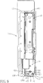
- the lock-releasing button 422 is operable to push the latching member 421 away from the first latching hole 1301 along a rear-to-front release direction (II) (see Fig. 9 ).
- the biasing spring 423 is a compression spring that is sleeved on the lock-releasing button 422 for biasing the lock-releasing button in a direction opposite to the release direction (II), so that the latching member 421 can be maintained in a latching position (see Fig. 8 ), where the latching member 421 is engaged to the first latching hole 1301.
- the lock-releasing button 422 is pressed along the release direction (II) so as to move forwardly.
- the biasing spring 423 is compressed, and the latching member 421 is gradually moved away from the first latching hole 1301.
- the latching member 421 is moved to a release position shown in Fig. 9 , the latching member 421 is completely detached from first latching hole 1301.
- the latching hooks 416 are first engaged to the respective second latching holes 1271, after which the lock-releasing button 422 is pressed to move the latching members 421 to the release position.
- the rear wall 411 of the side cover 41 is then brought to abut against the rear plate 130 of the upright frame body 113, such that the latching member 421 is aligned with the first latching hole 1301.
- the lock-releasing button 422 is released from being pressed, and the latching member 421 is automatically restored to the latching position through the restoring force of the biasing spring 423.
- the Point-of-Sale system 100 of this embodiment because of the abutment of the base plate 111 of the support base 11 with the flat surface through the foot pads 110, the structural design between the suspension arm 114 and the upright frame body 113, and the connecting relationship between the hinges 151 of the pivot mechanism 15 and the suspension arm 114, the support base 11 can stably support the first display screen 13. When the first display screen 13 is touched by a user, the first display screen 13 does not easily shake.
- the first opening portion 120 of the receiving notch 117 is exposed, so that the first display screen 13 can be easily and quickly detached from or assembled to the suspension arm 114, thereby facilitating repair or replacement of the first display screen 13.
- the side cover 41 of the host computer 4 can be conveniently and quickly detached from or assembled to the upright frame body 113, thereby facilitating repair or replacement of the electronic unit 43 of the host computer. Therefore, the objects of this invention can be achieved.
Landscapes
- Engineering & Computer Science (AREA)
- General Engineering & Computer Science (AREA)
- Mechanical Engineering (AREA)
- Physics & Mathematics (AREA)
- General Physics & Mathematics (AREA)
- Cash Registers Or Receiving Machines (AREA)
- Display Racks (AREA)
Description
- The invention relates to a display device, more particularly to a display device having a support base for supporting a display screen and a Point-of-Sale (POS) system having the display device.
- A Point-of-Sale (POS) system currently applied in supermarkets, malls or stores is usually used in conjunction with a cash register. The POS system includes a support base supported on a flat surface, and a touch-type display screen disposed on the support base for touching by a user. Since the force applied on the display screen is not the same for each user, the display screen is likely to shake, thereby making it inconvenient to use.
- Further, assembly and disassembly of the display screen and the host computer of an existing POS system are complicated and inconvenient, so that when repair or replacement of the display screen or the host computer is desired, a lot of working hours is consumed.
-
EP 1 995 507 A2claim 1 which includes a body stand unit; a display displaying unit; and an arm unit, arranged upright from the body stand unit, for supporting the display displaying unit; where the arm unit is arranged on either left or right end side from a center in a horizontal direction of the display displaying unit, and supports the display displaying unit in a cantilever state. - F O Sommez: "Optimal shape design of shoulder fillets for flat and round bars under various loadings", , vol. 223 24 February 2009 (2009-02-24), pages 1741-1754, XP002729716, Department of Mechanical Engineering, Bogazici University, Bebek 34342, Istanbul, Turkey describes an optimization for fillets which are usually the most critical regions in mechanical parts especially under fatigue loading, considering that an increase in the maximum stress level considerably shortens the fatigue life of a part. The aim is to find the best shape for a fillet in a shouldered shaft or plate so that the maximum equivalent stress has the lowest possible value.
- www.e-CAD-Engineering.co.uk: "Setting-up and running a Solidworks simulation study", , 5 June 2012 (2012-06-05), XP054975516, describes setting-up and running a Solidworks simulation study.
- It is an object of the present invention to provide a Point-of-Sale system having a display device, wherein a support base of the display device can stably support a display screen, so that when a user touches the display screen, the display screen will not easily shake, and wherein the display screen of the display device and a host computer can be conveniently and quickly assembled to and disassembled from a support base to facilitate repair or replacement of the display screen or the host computer.
- This object is achieved by a Point-of-Sale system of
claim 1. - The efficiency of the present invention resides in that because of the abutment of the base plate of the support base with the flat surface through the foot pads, the structural design between the suspension arm and the upright frame body, and the connecting relationship between the hinges of the pivot mechanism and the suspension arm, the support base can stably support the first display screen. When the first display screen is touched by a user, the first display screen does not easily shake. Furthermore, through the configuration of the receiving notch of the suspension arm, when the first display screen is rotated to the second position, the first opening portion of the receiving notch is exposed, so that the first display screen can be easily and quickly detached from or assembled to the suspension arm, thereby facilitating repair or replacement of the first display screen. Moreover, through the configuration of the locking mechanism, the side cover of the host computer can be conveniently and quickly detached from or assembled to the upright frame body, thereby facilitating repair or replacement of the electronic unit of the host computer.
- Other features and advantages of the present invention will become apparent in the following detailed description of the preferred embodiment with reference to the accompanying drawings, of which:
-
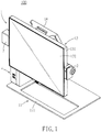
Fig. 1 is a perspective view of a Point-of-Sale (POS) system according to the preferred embodiment of this invention, illustrating a first display screen in a first position; -
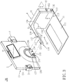
Fig. 2 is an exploded perspective view of the preferred embodiment; -
Fig. 3 is a partly exploded perspective view of the preferred embodiment taken from another angle; -
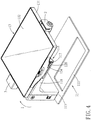
Fig. 4 is another perspective view of the preferred embodiment, illustrating the first display screen in a second position; -
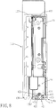
Fig. 5 is a schematic front view ofFig. 4 ; -
Fig. 6 is another exploded perspective view of the preferred embodiment, illustrating an assembling relation between an upright frame body and a host computer; -
Fig. 7 is a perspective view of a side cover of the preferred embodiment; -
Fig. 8 is a sectional view of the preferred embodiment taken along line 8-8 ofFig. 3 ; and -
Fig. 9 is a view similar toFig. 8 , but illustrating a latching member in a release position. - Referring to
Figs. 1 to 9 , a Point-of-Sale (POS)system 100 according to the preferred embodiment of the present invention comprises adisplay device 1, acard reader 2, ascanner 3 and a host computer 4. - The
display device 1 includes asupport base 11, afirst display screen 13, asecond display screen 14 and apivot mechanism 15. Thesupport base 11 includes abase plate 111 and asupport frame 112. Thesupport frame 112 includes anupright frame body 113 disposed on thesupport base 11 and having aside surface 115, and asuspension arm 114 projecting from theside surface 115 along a horizontal direction (Y) and spaced apart from and disposed above thebase plate 111. A junction of a bottom end of thesuspension arm 114 and theside surface 115 is formed with acurved chamfer 116. Thefirst display screen 13 is a touch-type display screen for touching/pressing and viewing of related information by a store clerk at the service end. Thesecond display screen 14 is rotatably pivoted to the back of thefirst display screen 13 for viewing of the related information by a customer. Thepivot mechanism 15 is disposed between thesuspension arm 114 and thefirst display screen 13. Thefirst display screen 13 is rotatable relative to thesuspension arm 114 through thepivot mechanism 15. As such, a viewing angle of thefirst display screen 13 can be adjusted. - The
card reader 2 is disposed on one side of thefirst display screen 13 for reading information from, for example, a bank card. Thescanner 3 is disposed on another side of thefirst display screen 13 that is opposite to thecard reader 2 for scanning a bar code on the package of an article. The host computer 4 is disposed on theupright frame body 113, and is electrically connected to the first andsecond display screens card reader 2 and thescanner 3. After a store clerk swipes a card through thecard reader 2, related information will be displayed on the first andsecond display screens scanner 3, related information will be displayed on the first andsecond display screens - Because of the presence of the
curved chamfer 116 at the junction of the bottom end of thesuspension arm 114 and theside surface 115 of theupright frame body 113, occurrence of stress concentration on the junction of thesuspension arm 114 and theside surface 115 can be avoided, and a support force for supporting thesuspension arm 114 can be enhanced, thereby preventing breakage of thesuspension arm 114. Thus, thesupport base 11 can stably support thefirst display screen 13, so that when a user touches thefirst display screen 13, it will not easily shake. - With reference to
Figs. 2 ,4 and5 , thesuspension arm 114 of thesupport frame 112 projects integrally from and is in one piece with theside surface 115 of theupright frame body 113. Thesupport frame 112 and thebase plate 111 are made of metal. Specifically, each of thesupport frame 112 and thebase plate 111 is produced by pressure casting an aluminum alloy. Thebase plate 111 is fixed to a bottom end of theupright frame body 113 using, for example, a screw-fastening method. Since each of thesupport frame 112 and thebase plate 111 is made of metal, theentire support base 11 has a good structural strength, so that thesupport base 11 can stably support thefirst display screen 13, and thesecond display screen 14, thecard reader 2 and thescanner 3 that are assembled to thefirst display screen 13. Furthermore, in this embodiment, thebase plate 111 is rectangular and has a first length (L1) extending along the horizontal direction (Y), and thesuspension arm 114 has a second length (L2) also extending along the horizontal direction (Y), but smaller than the first length (L1). This can prevent thesupport base 11 from toppling over as a result of a torque generated from a downward force applied to thesuspension arm 114 by the first andsecond display screens card reader 2 and thescanner 3. - Moreover, the
support base 11 further includes a plurality offoot pads 110 disposed on a bottom surface of thebase plate 111. Each of thefoot pads 110 can be fixed to the bottom surface of thebase plate 111 using, for example, an adhesive bonding method. Eachfoot pad 110 is made of a flexible material, such as rubber or silicone, and is used for abutting against a flat surface (not shown), such as a tabletop. Through this, friction between thebase plate 111 and the flat surface can be enhanced, so that thebase plate 111 cannot easily slide relative to the flat surface. - The
suspension arm 114 is formed with areceiving notch 117. Thepivot mechanism 15 includes twohinges 151 disposed between thesuspension arm 114 and thefirst display screen 13. Thehinges 151 are fixed in thereceiving notch 117 in a spaced apart relationship along the horizontal direction (Y) so as to distribute supporting forces that support thefirst display screen 13. - The
first display screen 13 includes ahousing 131, and adisplay body 132 disposed in thehousing 131. Thehousing 131 has arear plate 133, and a protrudingcover 134 projecting rearwardly from therear plate 133 in proximity to a bottom end thereof. Left and right sides of the protrudingcover 134 are respectively formed with an opening 135 (only one opening 135 is shown inFig. 3 ). Thehinges 151 are disposed in theprotruding cover 134. Eachhinge 151, as shown inFig. 2 , includes afixing member 152, a connectingmember 153 and twoscrews 154. Thefixing member 151 includes apivot portion 155 parallel to the horizontal direction (Y), and afixed plate 156 formed on one end of thepivot portion 155 and projecting out of arespective opening 135. The twoscrews 154 are used to fix thefixed plate 156 to thesuspension arm 114. The connectingmember 153 is rotatably pivoted to thepivot portion 155, and is fixedly screwed to therear plate 133. Through this configuration, thefirst display screen 13 is rotatable relative to thesuspension arm 114 about thepivot portions 155 of thehinges 151 between a first position, as shown inFig. 1 , and a second position, as shown inFig. 4 . - The
suspension arm 114 includes afront side wall 118, atop wall 119 connected to a top end of thefront side wall 118, and two positioningpieces 122 disposed in the receivingnotch 117. The receivingnotch 117 has afirst opening portion 120 formed in thefront side wall 118, and asecond opening portion 121 formed in thetop wall 119 and communicating with thefirst opening portion 120. Each of thepositioning pieces 122 has anabutment surface 123 abutting against the fixedplate 156 of therespective hinge 151, and two supportingribs 124 projecting from theabutment surface 123 and located spaced apart below thetop wall 119. Theabutment surface 123 is formed with two threadedholes 125 for receiving the respective screws 154. Through this, the fixedplate 156 of eachhinge 151 can be fixed to theabutment surface 123 of therespective positioning piece 122. Further, thetop wall 119 of thesuspension arm 114 and the supportingribs 124 of eachpositioning piece 122 cooperatively clamp upper and lower ends of the fixedplate 156 of thecorresponding hinge 151. As such, apart from preventing upward and downward movement of the fixedplate 156, stability of supporting the fixedplate 156 can also be enhanced. It should be noted that the number of the supportingribs 124 of eachpositioning piece 122 is not limited to two, and may be one or more than two. - With reference to
Figs. 1 and2 , when thefirst display screen 13 is in the first position, thefirst display screen 13 is upright, the store clerk can view or touch thedisplay body 132 of thefirst display screen 13, and the customer can view thesecond display screen 14. Furthermore, thehousing 131 of thefirst display screen 13 can cover thefirst opening portion 120 of the receivingnotch 117, so that thescrews 154 of thehinges 151 that face thefirst opening portion 120 are also covered by thehousing 131. - With reference to
Figs. 2 ,4 and5 , when thefirst display screen 13 is rotated from the first position to the second position along the direction of an arrow (I), thefirst display screen 13 is horizontal, and thefirst opening portion 120 is exposed and is not covered by thehousing 131 of thefirst display screen 13. At this time, a repairman can conveniently and quickly insert an auxiliary tool, such as a screwdriver, into the exposed first openingportion 120 to loosen and remove thescrews 154 from the threaded holes 125. As such, thefirst display screen 13 can be quickly detached from thesuspension arm 114 to facilitate repair or replacement of thefirst display screen 13, thesecond display screen 14, thecard reader 2 or thescanner 3. To assemble thefirst display screen 13 back to thesuspension arm 114, the protrudingcover 134 of thehousing 131 is first placed in the receivingnotch 117 via thefirst opening portion 120 such that the fixedplate 156 of eachhinge 151 abuts against theabutment surface 123 of therespective positioning piece 122. Afterwards, thescrews 154 are inserted through the fixedplate 156 to engage with the respective threadedholes 125. Hence, thefirst display screen 13 is assembled back to thesuspension arm 114. - Referring once again to
Figs. 2 ,3 and5 , theupright frame body 113 of thesupport frame 112 includes atop plate 126 and afront plate 127. Thefront side wall 118 of thesuspension arm 114 is connected to and flush with thefront plate 127, so that thefirst display screen 13 is proximate to the store clerk to facilitate touching or viewing of thefirst display screen 13 by the store clerk. Further, thetop wall 119 of thesuspension arm 114 is connected to and flush with thetop plate 126. Thebase plate 111, theupright frame body 113 and thesuspension arm 114 can cooperatively define a largeaccommodating space 16 for accommodating, for example, a cash register or other peripherals. - Because the
front side wall 118 is flush with thefront plate 127 and thetop wall 119 is flush with thetop plate 126, a junction of thefront side wall 118 and theupright frame body 113 and a junction of thetop wall 119 and theupright frame body 113 will not form connecting structures with sharp angles so as to avoid occurrence of stress concentration on the connecting structures. Thesuspension arm 114 further includes a curved connectingwall 128 connected between thefront side wall 118 and thetop wall 119. Thecurved chamfer 116 is formed between the curved connectingwall 128 and theside surface 115. Since thefront side wall 118 and thetop wall 119 are flush with thefront plate 127 and thetop plate 126, respectively, and the curved connectingwall 128 is connected to theside surface 115 through thecurved chamfer 116, the connection of theentire suspension arm 114 with theupright frame body 113 will not form connecting structures with sharp angles. This can effectively avoid occurrence of stress concentration and prevent thesuspension arm 114 from breaking. - With reference to
Figs. 5 to 7 , the host computer 4 includes aside cover 41 assembled to a side of theupright frame body 113 that is opposite to theside surface 115, alocking mechanism 42 disposed on theside cover 41 to lock the same on theupright frame body 113, and anelectronic unit 43. Theside cover 41 and theupright frame body 113 cooperatively define a receivingspace 44. Thesuspension arm 114 is formed with a throughhole 129 communicating with the receivingnotch 117 and the receivingspace 44. Theelectronic unit 43 is disposed in the receivingspace 44, and includes acircuit board 431, and acable 432 electrically connected to thecircuit board 431. Thecable 432 passes through the throughhole 129 and apassage hole 136 in thehousing 131. Thefirst display screen 13, thesecond display screen 14, thecard reader 2 and thescanner 3 are electrically connected to thecircuit board 431 through thecable 432. Thecable 432 is used to transmit electrical signals to the first and second display screens 13, 14, thecard reader 2 and thescanner 3. By passing thecable 432 through the throughhole 129, thecable 432 can be hidden and is prevented from being exposed, thereby enhancing an overall aesthetic appearance of the Point-of-Sale system 100. - Referring to
Fig. 8 , in combination withFigs. 6 and7 , theupright frame body 113 further includes arear plate 130 opposite to and spaced apart from thefront plate 127 and formed with afirst latching hole 1301. Thefront plate 127 is formed with two second latching holes 1270 spaced apart in an up-down direction. The side cover 41 includes arear wall 411, and a mountingseat 412 indented inwardly and forwardly from therear wall 411. The mountingseat 412 defines arecess 413, and is formed with a throughhole 414 communicating therecess 413 with the receivingspace 44. The side cover 41 further includes afront wall 415, and two latchinghooks 416 projecting from thefront wall 415 and engaged to the respective second latching holes 1271. - The
locking mechanism 42 includes a latchingmember 421 engaged to thefirst latching hole 1301, a lock-releasingbutton 422 that is disposed in therecess 413 and that extends through the throughhole 414 to connect with the latchingmember 421, and abiasing spring 423 disposed in therecess 413. The lock-releasingbutton 422 is operable to push the latchingmember 421 away from thefirst latching hole 1301 along a rear-to-front release direction (II) (seeFig. 9 ). The biasingspring 423 is a compression spring that is sleeved on the lock-releasingbutton 422 for biasing the lock-releasing button in a direction opposite to the release direction (II), so that the latchingmember 421 can be maintained in a latching position (seeFig. 8 ), where the latchingmember 421 is engaged to thefirst latching hole 1301. - Referring to
Fig. 9 , in combination withFig. 8 , to detach the side cover 41 from theupright frame body 113 so as to perform repair or replacement of theelectronic unit 43, the lock-releasingbutton 422 is pressed along the release direction (II) so as to move forwardly. During movement of the lock-releasingbutton 422 in the release direction (II), the biasingspring 423 is compressed, and the latchingmember 421 is gradually moved away from thefirst latching hole 1301. When the latchingmember 421 is moved to a release position shown inFig. 9 , the latchingmember 421 is completely detached fromfirst latching hole 1301. At this time, therear wall 411 of theside cover 41 can be pulled outwardly, and the latching hooks 416 are disengaged from the respective second latching holes 1274 (seeFig. 6 ). Hence, removal of the side cover 41 from theupright frame body 113 is achieved, so that repair or replacement of theelectronic unit 43 can be facilitated. - With reference to
Figs. 6 to 8 , to assemble theside cover 41 back to theupright frame body 113, the latching hooks 416 are first engaged to the respective second latching holes 1271, after which the lock-releasingbutton 422 is pressed to move the latchingmembers 421 to the release position. Therear wall 411 of theside cover 41 is then brought to abut against therear plate 130 of theupright frame body 113, such that the latchingmember 421 is aligned with thefirst latching hole 1301. Finally, the lock-releasingbutton 422 is released from being pressed, and the latchingmember 421 is automatically restored to the latching position through the restoring force of the biasingspring 423. Through the configuration of thelocking mechanism 42, theside cover 41 can be conveniently and quickly detached from or assembled to theupright frame body 113 to perform repair or replacement of theelectronic unit 43. - In summary, the Point-of-
Sale system 100 of this embodiment, because of the abutment of thebase plate 111 of thesupport base 11 with the flat surface through thefoot pads 110, the structural design between thesuspension arm 114 and theupright frame body 113, and the connecting relationship between thehinges 151 of thepivot mechanism 15 and thesuspension arm 114, thesupport base 11 can stably support thefirst display screen 13. When thefirst display screen 13 is touched by a user, thefirst display screen 13 does not easily shake. Furthermore, through the configuration of the receivingnotch 117 of thesuspension arm 114, when thefirst display screen 13 is rotated to the second position, thefirst opening portion 120 of the receivingnotch 117 is exposed, so that thefirst display screen 13 can be easily and quickly detached from or assembled to thesuspension arm 114, thereby facilitating repair or replacement of thefirst display screen 13. Moreover, through the configuration of the locking mechanism 4, theside cover 41 of the host computer 4 can be conveniently and quickly detached from or assembled to theupright frame body 113, thereby facilitating repair or replacement of theelectronic unit 43 of the host computer. Therefore, the objects of this invention can be achieved.
Claims (8)
- A Point-of-Sale (POS) system, comprising:a display device includinga support base (11) including a base plate (111) and a support frame (112), said support frame (112) including an upright frame body (113) disposed on said base plate (111) and having a side surface (115), and a suspension arm (114) projecting from said side surface (115) along a horizontal direction (Y) and spaced apart from and disposed above said base plate (111), a junction of a bottom end of said suspension arm (114) and said side surface (115) being formed with a curved chamfer (116),a touch-type display screen (13), anda pivot mechanism (15) disposed between said suspension arm (114) and said display screen (13), said display screen (13) being rotatable relative to said suspension arm (114) throughsaid pivot mechanism (15), characterized in that the point-of-sale system further comprises a card reader (2) disposed on one side of said display screen (13); anda host computer (4) disposed on said upright frame body (113) and electrically connected to said display screen and said card reader, said host computer (4) including a side cover (41) assembled to a side of said upright frame body (113) that is opposite to said side surface (115), and a locking mechanism (42) disposed on said side cover (41) to lock said side cover (41) on said upright frame body (113) ; wherein said upright frame body (113) is formed with a first latching hole (1301) and a second latching hole (1271) on two opposite sides thereof, said locking mechanism (42) including a latching member (421) engaged to said first latching hole (1301), a lock-releasing button (422) connected to said latching member (421), and a biasing spring (423), said lock-releasing button (422) being operable to push said latching member (421) away from said first latching hole (1301) along a release direction (II), said biasing spring (423) biasing said lock-releasing button (422) in a direction opposite to said release direction (II), said side cover (41) including an latching hook (416) engaged to said second latching hole (1271).
- The POS system as claimed in Claim 11, characterized in that said suspension arm (114) projects integrally from and is in one piece with said side surface (115), and said base plate (111) and said support frame (112) are made of metal.
- The POS system as claimed in Claim 12, characterized in that said base plate (111) has a first length (L1) extending along said horizontal direction (Y), and said suspension arm (114) has a second length (L2) extending along said horizontal direction (Y) and smaller than said first length (L1).
- The POS system as claimed in Claim 13, characterized in that said suspension arm (114) is formed with a receiving notch (117), said pivot mechanism (15) including two hinges (151) disposed between said suspension arm (114) and said first display screen (13), said hinges (151) being fixed in said receiving notch (117) in a spaced apart relationship along said horizontal direction (Y).
- The POS system as claimed in Claim 14, characterized in that said receiving notch (117) has a first opening portion (120), and a second opening portion (121) communicating with said first opening portion (120), said display screen (13) including a housing (131), each of said hinges (151) being disposed in said housing (131) and including a fixed plate (156) projecting out of said housing (131), and a screw (154) fixing said fixed plate (156) to said suspension arm (114), said screw (154) facing said first opening portion (120), said display screen (13) being rotatable relative to said suspension arm (114) between a first position, where said housing (131) covers said first opening portion (120), and a second position, where said first opening portion (120) is exposed.
- The POS system as claimed in Claim 15, characterized in that said suspension arm (114) includes a front side wall (118), a top wall (119) connected to a top end of said front side wall (118), and two positioning pieces (122) disposed in said receiving notch (117), said first opening portion (120) being formed in said front side wall (118), said second opening portion (121) being formed in said top wall (119), each of said positioning pieces (122) having an abutment surface (123) abutting against said fixed plate (156) of a respective one of said hinges (151), and a supporting rib (124) projecting from said abutment surface (123), said supporting ribs (124) of said positioning pieces (122) being located spaced apart below said top wall (119), said abutment surface (123) being formed with a threaded hole (125) for receiving said screw (154), said top wall (119) and said supporting rib (124) cooperatively clamping upper and lower ends of said fixed plate (156).
- The POS system as claimed in Claim 16, characterized in that said upright frame body (113) includes a top plate (126) and a front plate (127), said front side wall (118) of said suspension arm (114) being connected to and flush with said front plate (127), said top wall (119) of said suspension arm (114) being connected to and flush with said top plate (126), said base plate (111), said upright frame body (113) and said suspension arm (114) cooperatively defining an accommodating space (16), said suspension arm further including a curved connecting wall (128) connected between said front side wall (118) and said top wall (119), said curved chamfer (116) being formed between said side surface (115) and said curved connecting wall (128).
- The POS system as claimed in Claim 1, characterized in that said upright frame body (113) and said side cover (41) cooperatively define a receiving space (44), said suspension arm (114) being formed with a receiving notch (117), and a through hole (129) communicating with said receiving notch (117) and said receiving space (44), said display screen (13) including a housing (131), said host computer (4) further including a circuit board (431) disposed in said receiving space (44), and a cable (432) passing through said through hole (129) and said housing (131), said cable (432) being electrically connected to said display screen (13), said card reader (2) and said circuit board (431).
Applications Claiming Priority (3)
| Application Number | Priority Date | Filing Date | Title |
|---|---|---|---|
| TW102104832A TWI505068B (en) | 2013-02-07 | 2013-02-07 | A display device and a point-of-sale system having the display device |
| TW102301111F TWD157872S (en) | 2013-02-07 | 2013-02-07 | Point of Sale System |
| TW102202761U TWM457935U (en) | 2013-02-07 | 2013-02-07 | Display device and point of sale system having the display device |
Publications (4)
| Publication Number | Publication Date |
|---|---|
| EP2775192A2 EP2775192A2 (en) | 2014-09-10 |
| EP2775192A3 EP2775192A3 (en) | 2014-11-05 |
| EP2775192B1 true EP2775192B1 (en) | 2017-09-06 |
| EP2775192B8 EP2775192B8 (en) | 2017-12-13 |
Family
ID=49000308
Family Applications (1)
| Application Number | Title | Priority Date | Filing Date |
|---|---|---|---|
| EP13180253.0A Active EP2775192B8 (en) | 2013-02-07 | 2013-08-13 | Display device and point-of-sale system having the display device |
Country Status (1)
| Country | Link |
|---|---|
| EP (1) | EP2775192B8 (en) |
Cited By (1)
| Publication number | Priority date | Publication date | Assignee | Title |
|---|---|---|---|---|
| CN115930077A (en) * | 2022-12-08 | 2023-04-07 | 上海益邦智能技术股份有限公司 | An installation device and installation method for a building monitoring display screen |
Families Citing this family (7)
| Publication number | Priority date | Publication date | Assignee | Title |
|---|---|---|---|---|
| CN105674008B (en) * | 2014-11-19 | 2018-01-12 | 赛恩倍吉科技顾问(深圳)有限公司 | Support meanss |
| CN104989925B (en) * | 2015-07-28 | 2017-04-05 | 福州中澳科技有限公司 | A kind of horizontal quick-speed plug attachment means of display screen and its plug method |
| DE102016104966A1 (en) * | 2016-03-17 | 2017-11-23 | Bixolon Europe Gmbh | Holder for a display and / or input device |
| WO2017205409A1 (en) * | 2016-05-23 | 2017-11-30 | Vantage Point Products Corp. | Stand |
| TWI601902B (en) * | 2016-12-28 | 2017-10-11 | 晶達光電股份有限公司 | Suspended display structure |
| FR3094541B1 (en) * | 2019-03-29 | 2021-04-09 | Aures Tech | Cash register |
| CN112879765A (en) * | 2021-01-18 | 2021-06-01 | 济南和普威视光电技术有限公司 | Spherical photoelectric rotary table |
Family Cites Families (3)
| Publication number | Priority date | Publication date | Assignee | Title |
|---|---|---|---|---|
| US5904328A (en) * | 1997-06-23 | 1999-05-18 | Stb Systems, Inc. | Articulating computer monitor |
| JP2008292691A (en) * | 2007-05-23 | 2008-12-04 | Sony Corp | Display device |
| US20120145787A1 (en) * | 2010-12-10 | 2012-06-14 | Flytech Technology Co., Ltd. | Display device |
-
2013
- 2013-08-13 EP EP13180253.0A patent/EP2775192B8/en active Active
Cited By (1)
| Publication number | Priority date | Publication date | Assignee | Title |
|---|---|---|---|---|
| CN115930077A (en) * | 2022-12-08 | 2023-04-07 | 上海益邦智能技术股份有限公司 | An installation device and installation method for a building monitoring display screen |
Also Published As
| Publication number | Publication date |
|---|---|
| EP2775192A3 (en) | 2014-11-05 |
| EP2775192A2 (en) | 2014-09-10 |
| EP2775192B8 (en) | 2017-12-13 |
Similar Documents
| Publication | Publication Date | Title |
|---|---|---|
| EP2775192A2 (en) | Display device and point-of-sale system having the display device | |
| US8020761B2 (en) | Point-of-sale terminal system with integrated RF card reader and interchangeable base | |
| US8199476B2 (en) | Notebook computer | |
| US7265997B2 (en) | Mounting apparatus for mounting expansion cards in computer enclosure | |
| US20070038517A1 (en) | Point-of-sale terminal | |
| CN201628898U (en) | expansion card holder | |
| US7866623B2 (en) | Computer retail display stand | |
| US20080023612A1 (en) | Monitor with Interchangeable Base and Monitor Mount for Point-of-Sale Applications | |
| US7654446B2 (en) | Monitor with interchangeable base for point-of-sale applications | |
| US8462494B2 (en) | Panel fixing mechanism and displaying device thereof | |
| US12025262B1 (en) | Information handling system display stand mount | |
| TWI505068B (en) | A display device and a point-of-sale system having the display device | |
| TW201131335A (en) | Commercial terminal | |
| CN203630878U (en) | POS terminal with case structure | |
| CN101903917B (en) | Checkout system | |
| KR20180136290A (en) | Pos terminal device | |
| TWM457935U (en) | Display device and point of sale system having the display device | |
| US6674638B2 (en) | Fastening device | |
| JP6683389B1 (en) | POS terminal device | |
| US8134430B2 (en) | Trigger device used in a palmtop computer | |
| WO2013001870A1 (en) | Control device for information processing device and able to easily attach and remove connection section for externally connected apparatus | |
| US8087575B2 (en) | Printer with a touch panel | |
| CN104183065A (en) | Point-of-sale system | |
| JP3173596U (en) | Product price display board | |
| JP6737483B1 (en) | POS terminal device |
Legal Events
| Date | Code | Title | Description |
|---|---|---|---|
| PUAI | Public reference made under article 153(3) epc to a published international application that has entered the european phase |
Free format text: ORIGINAL CODE: 0009012 |
|
| 17P | Request for examination filed |
Effective date: 20130813 |
|
| AK | Designated contracting states |
Kind code of ref document: A2 Designated state(s): AL AT BE BG CH CY CZ DE DK EE ES FI FR GB GR HR HU IE IS IT LI LT LU LV MC MK MT NL NO PL PT RO RS SE SI SK SM TR |
|
| AX | Request for extension of the european patent |
Extension state: BA ME |
|
| PUAL | Search report despatched |
Free format text: ORIGINAL CODE: 0009013 |
|
| AK | Designated contracting states |
Kind code of ref document: A3 Designated state(s): AL AT BE BG CH CY CZ DE DK EE ES FI FR GB GR HR HU IE IS IT LI LT LU LV MC MK MT NL NO PL PT RO RS SE SI SK SM TR |
|
| AX | Request for extension of the european patent |
Extension state: BA ME |
|
| RIC1 | Information provided on ipc code assigned before grant |
Ipc: F16M 11/10 20060101AFI20140929BHEP Ipc: F16M 11/22 20060101ALI20140929BHEP |
|
| R17P | Request for examination filed (corrected) |
Effective date: 20150505 |
|
| RBV | Designated contracting states (corrected) |
Designated state(s): AL AT BE BG CH CY CZ DE DK EE ES FI FR GB GR HR HU IE IS IT LI LT LU LV MC MK MT NL NO PL PT RO RS SE SI SK SM TR |
|
| GRAP | Despatch of communication of intention to grant a patent |
Free format text: ORIGINAL CODE: EPIDOSNIGR1 |
|
| INTG | Intention to grant announced |
Effective date: 20170302 |
|
| GRAS | Grant fee paid |
Free format text: ORIGINAL CODE: EPIDOSNIGR3 |
|
| GRAA | (expected) grant |
Free format text: ORIGINAL CODE: 0009210 |
|
| AK | Designated contracting states |
Kind code of ref document: B1 Designated state(s): AL AT BE BG CH CY CZ DE DK EE ES FI FR GB GR HR HU IE IS IT LI LT LU LV MC MK MT NL NO PL PT RO RS SE SI SK SM TR |
|
| REG | Reference to a national code |
Ref country code: GB Ref legal event code: FG4D |
|
| REG | Reference to a national code |
Ref country code: AT Ref legal event code: REF Ref document number: 926271 Country of ref document: AT Kind code of ref document: T Effective date: 20170915 Ref country code: CH Ref legal event code: EP |
|
| REG | Reference to a national code |
Ref country code: IE Ref legal event code: FG4D |
|
| REG | Reference to a national code |
Ref country code: DE Ref legal event code: R096 Ref document number: 602013026065 Country of ref document: DE |
|
| REG | Reference to a national code |
Ref country code: CH Ref legal event code: NV Representative=s name: BOVARD AG PATENT- UND MARKENANWAELTE, CH |
|
| RIN2 | Information on inventor provided after grant (corrected) |
Inventor name: LIN, CHIUNG-CHI |
|
| REG | Reference to a national code |
Ref country code: NL Ref legal event code: FP |
|
| REG | Reference to a national code |
Ref country code: LT Ref legal event code: MG4D |
|
| PG25 | Lapsed in a contracting state [announced via postgrant information from national office to epo] |
Ref country code: HR Free format text: LAPSE BECAUSE OF FAILURE TO SUBMIT A TRANSLATION OF THE DESCRIPTION OR TO PAY THE FEE WITHIN THE PRESCRIBED TIME-LIMIT Effective date: 20170906 Ref country code: SE Free format text: LAPSE BECAUSE OF FAILURE TO SUBMIT A TRANSLATION OF THE DESCRIPTION OR TO PAY THE FEE WITHIN THE PRESCRIBED TIME-LIMIT Effective date: 20170906 Ref country code: FI Free format text: LAPSE BECAUSE OF FAILURE TO SUBMIT A TRANSLATION OF THE DESCRIPTION OR TO PAY THE FEE WITHIN THE PRESCRIBED TIME-LIMIT Effective date: 20170906 Ref country code: NO Free format text: LAPSE BECAUSE OF FAILURE TO SUBMIT A TRANSLATION OF THE DESCRIPTION OR TO PAY THE FEE WITHIN THE PRESCRIBED TIME-LIMIT Effective date: 20171206 Ref country code: LT Free format text: LAPSE BECAUSE OF FAILURE TO SUBMIT A TRANSLATION OF THE DESCRIPTION OR TO PAY THE FEE WITHIN THE PRESCRIBED TIME-LIMIT Effective date: 20170906 |
|
| REG | Reference to a national code |
Ref country code: AT Ref legal event code: MK05 Ref document number: 926271 Country of ref document: AT Kind code of ref document: T Effective date: 20170906 |
|
| PG25 | Lapsed in a contracting state [announced via postgrant information from national office to epo] |
Ref country code: ES Free format text: LAPSE BECAUSE OF FAILURE TO SUBMIT A TRANSLATION OF THE DESCRIPTION OR TO PAY THE FEE WITHIN THE PRESCRIBED TIME-LIMIT Effective date: 20170906 Ref country code: BG Free format text: LAPSE BECAUSE OF FAILURE TO SUBMIT A TRANSLATION OF THE DESCRIPTION OR TO PAY THE FEE WITHIN THE PRESCRIBED TIME-LIMIT Effective date: 20171206 Ref country code: LV Free format text: LAPSE BECAUSE OF FAILURE TO SUBMIT A TRANSLATION OF THE DESCRIPTION OR TO PAY THE FEE WITHIN THE PRESCRIBED TIME-LIMIT Effective date: 20170906 Ref country code: GR Free format text: LAPSE BECAUSE OF FAILURE TO SUBMIT A TRANSLATION OF THE DESCRIPTION OR TO PAY THE FEE WITHIN THE PRESCRIBED TIME-LIMIT Effective date: 20171207 Ref country code: RS Free format text: LAPSE BECAUSE OF FAILURE TO SUBMIT A TRANSLATION OF THE DESCRIPTION OR TO PAY THE FEE WITHIN THE PRESCRIBED TIME-LIMIT Effective date: 20170906 |
|
| PG25 | Lapsed in a contracting state [announced via postgrant information from national office to epo] |
Ref country code: RO Free format text: LAPSE BECAUSE OF FAILURE TO SUBMIT A TRANSLATION OF THE DESCRIPTION OR TO PAY THE FEE WITHIN THE PRESCRIBED TIME-LIMIT Effective date: 20170906 Ref country code: PL Free format text: LAPSE BECAUSE OF FAILURE TO SUBMIT A TRANSLATION OF THE DESCRIPTION OR TO PAY THE FEE WITHIN THE PRESCRIBED TIME-LIMIT Effective date: 20170906 Ref country code: CZ Free format text: LAPSE BECAUSE OF FAILURE TO SUBMIT A TRANSLATION OF THE DESCRIPTION OR TO PAY THE FEE WITHIN THE PRESCRIBED TIME-LIMIT Effective date: 20170906 |
|
| PG25 | Lapsed in a contracting state [announced via postgrant information from national office to epo] |
Ref country code: EE Free format text: LAPSE BECAUSE OF FAILURE TO SUBMIT A TRANSLATION OF THE DESCRIPTION OR TO PAY THE FEE WITHIN THE PRESCRIBED TIME-LIMIT Effective date: 20170906 Ref country code: SM Free format text: LAPSE BECAUSE OF FAILURE TO SUBMIT A TRANSLATION OF THE DESCRIPTION OR TO PAY THE FEE WITHIN THE PRESCRIBED TIME-LIMIT Effective date: 20170906 Ref country code: SK Free format text: LAPSE BECAUSE OF FAILURE TO SUBMIT A TRANSLATION OF THE DESCRIPTION OR TO PAY THE FEE WITHIN THE PRESCRIBED TIME-LIMIT Effective date: 20170906 Ref country code: IS Free format text: LAPSE BECAUSE OF FAILURE TO SUBMIT A TRANSLATION OF THE DESCRIPTION OR TO PAY THE FEE WITHIN THE PRESCRIBED TIME-LIMIT Effective date: 20180106 Ref country code: AT Free format text: LAPSE BECAUSE OF FAILURE TO SUBMIT A TRANSLATION OF THE DESCRIPTION OR TO PAY THE FEE WITHIN THE PRESCRIBED TIME-LIMIT Effective date: 20170906 |
|
| REG | Reference to a national code |
Ref country code: DE Ref legal event code: R097 Ref document number: 602013026065 Country of ref document: DE |
|
| REG | Reference to a national code |
Ref country code: FR Ref legal event code: PLFP Year of fee payment: 6 |
|
| PLBE | No opposition filed within time limit |
Free format text: ORIGINAL CODE: 0009261 |
|
| STAA | Information on the status of an ep patent application or granted ep patent |
Free format text: STATUS: NO OPPOSITION FILED WITHIN TIME LIMIT |
|
| PG25 | Lapsed in a contracting state [announced via postgrant information from national office to epo] |
Ref country code: DK Free format text: LAPSE BECAUSE OF FAILURE TO SUBMIT A TRANSLATION OF THE DESCRIPTION OR TO PAY THE FEE WITHIN THE PRESCRIBED TIME-LIMIT Effective date: 20170906 |
|
| 26N | No opposition filed |
Effective date: 20180607 |
|
| PG25 | Lapsed in a contracting state [announced via postgrant information from national office to epo] |
Ref country code: SI Free format text: LAPSE BECAUSE OF FAILURE TO SUBMIT A TRANSLATION OF THE DESCRIPTION OR TO PAY THE FEE WITHIN THE PRESCRIBED TIME-LIMIT Effective date: 20170906 |
|
| PG25 | Lapsed in a contracting state [announced via postgrant information from national office to epo] |
Ref country code: MC Free format text: LAPSE BECAUSE OF FAILURE TO SUBMIT A TRANSLATION OF THE DESCRIPTION OR TO PAY THE FEE WITHIN THE PRESCRIBED TIME-LIMIT Effective date: 20170906 |
|
| PG25 | Lapsed in a contracting state [announced via postgrant information from national office to epo] |
Ref country code: LU Free format text: LAPSE BECAUSE OF NON-PAYMENT OF DUE FEES Effective date: 20180813 |
|
| REG | Reference to a national code |
Ref country code: BE Ref legal event code: MM Effective date: 20180831 |
|
| REG | Reference to a national code |
Ref country code: IE Ref legal event code: MM4A |
|
| PG25 | Lapsed in a contracting state [announced via postgrant information from national office to epo] |
Ref country code: IE Free format text: LAPSE BECAUSE OF NON-PAYMENT OF DUE FEES Effective date: 20180813 |
|
| PG25 | Lapsed in a contracting state [announced via postgrant information from national office to epo] |
Ref country code: BE Free format text: LAPSE BECAUSE OF NON-PAYMENT OF DUE FEES Effective date: 20180831 |
|
| PG25 | Lapsed in a contracting state [announced via postgrant information from national office to epo] |
Ref country code: MT Free format text: LAPSE BECAUSE OF NON-PAYMENT OF DUE FEES Effective date: 20180813 |
|
| PG25 | Lapsed in a contracting state [announced via postgrant information from national office to epo] |
Ref country code: TR Free format text: LAPSE BECAUSE OF FAILURE TO SUBMIT A TRANSLATION OF THE DESCRIPTION OR TO PAY THE FEE WITHIN THE PRESCRIBED TIME-LIMIT Effective date: 20170906 |
|
| PG25 | Lapsed in a contracting state [announced via postgrant information from national office to epo] |
Ref country code: PT Free format text: LAPSE BECAUSE OF FAILURE TO SUBMIT A TRANSLATION OF THE DESCRIPTION OR TO PAY THE FEE WITHIN THE PRESCRIBED TIME-LIMIT Effective date: 20170906 Ref country code: HU Free format text: LAPSE BECAUSE OF FAILURE TO SUBMIT A TRANSLATION OF THE DESCRIPTION OR TO PAY THE FEE WITHIN THE PRESCRIBED TIME-LIMIT; INVALID AB INITIO Effective date: 20130813 |
|
| PG25 | Lapsed in a contracting state [announced via postgrant information from national office to epo] |
Ref country code: CY Free format text: LAPSE BECAUSE OF FAILURE TO SUBMIT A TRANSLATION OF THE DESCRIPTION OR TO PAY THE FEE WITHIN THE PRESCRIBED TIME-LIMIT Effective date: 20170906 Ref country code: MK Free format text: LAPSE BECAUSE OF NON-PAYMENT OF DUE FEES Effective date: 20170906 |
|
| PG25 | Lapsed in a contracting state [announced via postgrant information from national office to epo] |
Ref country code: AL Free format text: LAPSE BECAUSE OF FAILURE TO SUBMIT A TRANSLATION OF THE DESCRIPTION OR TO PAY THE FEE WITHIN THE PRESCRIBED TIME-LIMIT Effective date: 20170906 |
|
| PGFP | Annual fee paid to national office [announced via postgrant information from national office to epo] |
Ref country code: NL Payment date: 20210826 Year of fee payment: 9 |
|
| PGFP | Annual fee paid to national office [announced via postgrant information from national office to epo] |
Ref country code: IT Payment date: 20210820 Year of fee payment: 9 |
|
| PGFP | Annual fee paid to national office [announced via postgrant information from national office to epo] |
Ref country code: CH Payment date: 20210823 Year of fee payment: 9 |
|
| REG | Reference to a national code |
Ref country code: CH Ref legal event code: PL |
|
| REG | Reference to a national code |
Ref country code: NL Ref legal event code: MM Effective date: 20220901 |
|
| PG25 | Lapsed in a contracting state [announced via postgrant information from national office to epo] |
Ref country code: LI Free format text: LAPSE BECAUSE OF NON-PAYMENT OF DUE FEES Effective date: 20220831 Ref country code: CH Free format text: LAPSE BECAUSE OF NON-PAYMENT OF DUE FEES Effective date: 20220831 |
|
| PG25 | Lapsed in a contracting state [announced via postgrant information from national office to epo] |
Ref country code: NL Free format text: LAPSE BECAUSE OF NON-PAYMENT OF DUE FEES Effective date: 20220901 |
|
| PG25 | Lapsed in a contracting state [announced via postgrant information from national office to epo] |
Ref country code: IT Free format text: LAPSE BECAUSE OF NON-PAYMENT OF DUE FEES Effective date: 20220813 |
|
| PGFP | Annual fee paid to national office [announced via postgrant information from national office to epo] |
Ref country code: DE Payment date: 20250827 Year of fee payment: 13 |
|
| PGFP | Annual fee paid to national office [announced via postgrant information from national office to epo] |
Ref country code: GB Payment date: 20250827 Year of fee payment: 13 |
|
| PGFP | Annual fee paid to national office [announced via postgrant information from national office to epo] |
Ref country code: FR Payment date: 20250825 Year of fee payment: 13 |