EP2774855A1 - Device for removing space debris and method for removing space debris - Google Patents
Device for removing space debris and method for removing space debris Download PDFInfo
- Publication number
- EP2774855A1 EP2774855A1 EP12844873.5A EP12844873A EP2774855A1 EP 2774855 A1 EP2774855 A1 EP 2774855A1 EP 12844873 A EP12844873 A EP 12844873A EP 2774855 A1 EP2774855 A1 EP 2774855A1
- Authority
- EP
- European Patent Office
- Prior art keywords
- debris
- target
- space
- space debris
- harpoon
- Prior art date
- Legal status (The legal status is an assumption and is not a legal conclusion. Google has not performed a legal analysis and makes no representation as to the accuracy of the status listed.)
- Granted
Links
Images



Classifications
-
- B—PERFORMING OPERATIONS; TRANSPORTING
- B64—AIRCRAFT; AVIATION; COSMONAUTICS
- B64G—COSMONAUTICS; VEHICLES OR EQUIPMENT THEREFOR
- B64G1/00—Cosmonautic vehicles
- B64G1/22—Parts of, or equipment specially adapted for fitting in or to, cosmonautic vehicles
- B64G1/24—Guiding or controlling apparatus, e.g. for attitude control
- B64G1/32—Guiding or controlling apparatus, e.g. for attitude control using earth's magnetic field
-
- B—PERFORMING OPERATIONS; TRANSPORTING
- B64—AIRCRAFT; AVIATION; COSMONAUTICS
- B64G—COSMONAUTICS; VEHICLES OR EQUIPMENT THEREFOR
- B64G1/00—Cosmonautic vehicles
- B64G1/10—Artificial satellites; Systems of such satellites; Interplanetary vehicles
- B64G1/1078—Maintenance satellites
- B64G1/1081—Maintenance satellites for debris removal
-
- B—PERFORMING OPERATIONS; TRANSPORTING
- B64—AIRCRAFT; AVIATION; COSMONAUTICS
- B64G—COSMONAUTICS; VEHICLES OR EQUIPMENT THEREFOR
- B64G1/00—Cosmonautic vehicles
- B64G1/22—Parts of, or equipment specially adapted for fitting in or to, cosmonautic vehicles
- B64G1/64—Systems for coupling or separating cosmonautic vehicles or parts thereof, e.g. docking arrangements
- B64G1/646—Docking or rendezvous systems
- B64G1/6462—Docking or rendezvous systems characterised by the means for engaging other vehicles
-
- B—PERFORMING OPERATIONS; TRANSPORTING
- B64—AIRCRAFT; AVIATION; COSMONAUTICS
- B64G—COSMONAUTICS; VEHICLES OR EQUIPMENT THEREFOR
- B64G1/00—Cosmonautic vehicles
- B64G1/22—Parts of, or equipment specially adapted for fitting in or to, cosmonautic vehicles
- B64G1/64—Systems for coupling or separating cosmonautic vehicles or parts thereof, e.g. docking arrangements
- B64G1/648—Tethers
-
- B—PERFORMING OPERATIONS; TRANSPORTING
- B64—AIRCRAFT; AVIATION; COSMONAUTICS
- B64G—COSMONAUTICS; VEHICLES OR EQUIPMENT THEREFOR
- B64G1/00—Cosmonautic vehicles
- B64G1/22—Parts of, or equipment specially adapted for fitting in or to, cosmonautic vehicles
- B64G1/66—Arrangements or adaptations of apparatus or instruments, not otherwise provided for
-
- B—PERFORMING OPERATIONS; TRANSPORTING
- B64—AIRCRAFT; AVIATION; COSMONAUTICS
- B64G—COSMONAUTICS; VEHICLES OR EQUIPMENT THEREFOR
- B64G1/00—Cosmonautic vehicles
- B64G1/22—Parts of, or equipment specially adapted for fitting in or to, cosmonautic vehicles
- B64G1/24—Guiding or controlling apparatus, e.g. for attitude control
- B64G1/26—Guiding or controlling apparatus, e.g. for attitude control using jets
-
- B—PERFORMING OPERATIONS; TRANSPORTING
- B64—AIRCRAFT; AVIATION; COSMONAUTICS
- B64G—COSMONAUTICS; VEHICLES OR EQUIPMENT THEREFOR
- B64G1/00—Cosmonautic vehicles
- B64G1/22—Parts of, or equipment specially adapted for fitting in or to, cosmonautic vehicles
- B64G1/24—Guiding or controlling apparatus, e.g. for attitude control
- B64G1/36—Guiding or controlling apparatus, e.g. for attitude control using sensors, e.g. sun-sensors, horizon sensors
Definitions
- the present invention relates to a space debris removing device and a space debris removing method, and relates in particular to a space debris removing device and a space debris removing method that are suitable for removing relatively large-sized space debris such as a used satellite or rocket orbiting the earth.
- satellites for various purposes such as military satellites, communication satellites, scientific satellites, observation satellites and navigation satellites, are orbiting the earth.
- the satellites When the satellites fail and become non-functional or end their duty and reach the end of their service life, the satellites are often left in orbit as they are and become space debris.
- wreckage of a rocket or the like used for launching a satellite or the like is also left in orbit as space debris.
- several thousand pieces of space debris or more are in orbit and a phase of self-reproduction in which the number of pieces is increased by natural collisions has started.
- At least about 5 pieces of space debris need to be removed yearly. Space debris is attracted by terrestrial gravitation, and falls and disappears eventually, however, a gravity fall requires many years and it is not efficient. So, a method for positively removing space debris is already proposed (for instance, see Patent Document 1 and Patent Document 2).
- a pressure receiving device for receiving a fine amount of atmosphere and solar light radiation pressure is configured by a circular or polygonal film material, and by attaching the pressure receiving device to space debris already orbiting in space or a spacecraft to be launched hereafter through a string, an important orbit is protected by a fall to the ground or orbit change of the space debris or the spacecraft after use.
- a method of driving a harpoon or a method of attaching the pressure receiving device by a robot arm is used for attachment of the pressure receiving device.
- a tether device for space debris orbit conversion including a conductive tether which is attached to space debris such as a broken satellite or satellite wreckage or the like and obtains force of changing the orbit of the space debris by electromagnetic interaction with a geomagnetic field
- the tether device for the space debris orbit conversion includes a capture mechanism capable of gripping a structural part of the space debris and a tether mechanism connected to the capture mechanism and extensibly holding the tether, and after gripping the space debris by the capture mechanism, the tether is extended by the tether mechanism, the robot arm is detached, and the tether device for the space debris orbit conversion is dumped integrally with the space debris.
- the present invention has been made in view of the problems, and has an object to provide a space debris removing device and a space debris removing method, capable of easily attaching a deceleration device to the space debris undergoing the tumbling motion.
- a space debris removing device which removes space debris undergoing an irregular tumbling motion from an orbit by capturing and decelerating the space debris, including a propulsion device for performing approach and attitude control to target debris which is the space debris to be removed, a capture device having a harpoon which can be ejected toward the target debris, an observation device for observing a motion of the target debris and calculating a capture position and a capture attitude at which the harpoon can be driven into a hollow portion of the target debris, a deceleration device directly or indirectly connected to the harpoon, for decelerating the target debris, and a body part on which the propulsion device, the capture device, the observation device and the deceleration device are mounted.
- the harpoon may include a pointed end part having a barb part that can be locked to the target debris, a stopper part to be in contact with a surface of the target debris, a thrust generation part for ejecting the harpoon, and a wire for connecting the harpoon to the body part.
- the barb part may be configured so as to be closed when passing through the target debris and be opened after passing through the target debris.
- the harpoon may be configured such that an elastic body disposed so as to cover the pointed end part on a front surface of the stopper part is provided, and by compressing the elastic body between the target debris surface and the stopper part when the pointed end part is locked to the target debris, scattering of broken pieces generated when the harpoon passes through is suppressed.
- the plurality of pointed end parts may be disposed on a surface of the stopper part and each of the pointed end parts may be configured so as to be capable of being pulled in when abutted to a location at which the pointed end part cannot pass through the surface of the target debris.
- a wire winding device capable of winding the wire may be provided, and by winding the wire after locking the pointed end part to the target debris, the body part may be closely fitted to the target debris.
- a buffer material for mitigating an impact when closely fitting the body part to the target debris may be disposed at the body part.
- a plurality of binding legs turnably disposed at the body part may be provided, and after the body part is closely fitted to the target debris, the binding legs may be expanded to fix the body part to the target debris, and the motion of the target debris may be suppressed using the propulsion device.
- the plurality of capture devices may be disposed at the body part.
- the deceleration device may include a conductive tether to be discharged into space, and a distal end part disposed at a distal end of the conductive tether and provided with thrust generation means for generating thrust.
- the deceleration device may include a conductive tether to be discharged into space, a distal end part disposed at a distal end of the conductive tether and provided with thrust generation means for generating thrust, and a connector for connecting a rear end of the conductive tether to the wire, and the wire may be connected to the body part through the conductive tether and the distal end part.
- the conductive tether may be connected so as to be separated from the body part. Also, the distal end part may be configured by the body part.
- a space debris removing method which removes the space debris undergoing an irregular tumbling motion from the orbit by capturing and decelerating the space debris, including an orbit injecting process of injecting the space debris removing device onto the orbit of target debris which is the space debris to be removed, an approaching process of making the space debris removing device approach the target debris, an observing and moving process of observing a motion of the target debris after the space debris removing device reaches an observation position, calculating a capture position and a capture attitude at which a harpoon can be driven into the target debris, and moving the space debris removing device to the capture position and the capture attitude, a capturing process of driving the harpoon into the target debris and connecting the space debris removing device and the target debris, and a decelerating process of decelerating the target debris by the space debris removing device.
- the capturing process may include a closely fitting process of winding a wire connected to the harpoon after the harpoon is driven into the target debris, and closely fitting the space debris removing device to the target debris.
- the capturing process may include a binding process of expanding binding legs disposed to the space debris removing device and binding the target debris after the space debris removing device is closely fitted to the target debris, and a motion suppressing process of suppressing a motion of the target debris by a propulsion device disposed at the space debris removal device.
- the observing and moving process may calculate the capture position and the capture attitude so as to drive the harpoon into a hollow portion of the target debris.
- the decelerating process may be a process of decelerating the target debris by discharging a conductive tether from the space debris removing device into space.
- the space debris removing device and the space debris removing method of the present invention by making the space debris removing device approach the target debris, calculating the capture position and the capture attitude at which the harpoon can be driven into the target debris, driving the harpoon and then decelerating the target debris, an orbit of the target debris is changed and the target debris can be made to fall down to the earth and disappear. Also, the harpoon can be driven from a position away from the target debris, and even when the target debris is undergoing the tumbling motion, the target debris can be captured in the state that the space debris removing device and the target debris do not collide, and the deceleration device can be easily attached.
- the wire connected to the harpoon is not easily wound around the target debris undergoing the tumbling motion, and an operation state of the deceleration device can be stabilized. Further, by fixing the space debris removing device to the target debris by the binding legs, the tumbling motion of the target debris can be suppressed using the propulsion device, and the operation state of the deceleration device can be stabilized more.
- FIG.1 is an overall schematic diagram illustrating an orbit injecting process to a capturing process of the space debris removing method according to a first embodiment of the present invention.
- FIG.2 is an overall schematic diagram illustrating a decelerating process of the space debris removing method according to the first embodiment of the present invention.
- FIG.3 is a flowchart illustrating the space debris removing method according to the first embodiment of the present invention.
- FIG.4 is a flowchart illustrating a modification of the space debris removing method according to the first embodiment of the present invention.
- the space debris removing method is for removing space debris undergoing an irregular tumbling motion from an orbit by capturing and decelerating the space debris as illustrated in FIG.1 to FIG.3 , and includes: an orbit injecting process (Step 1) of injecting a space debris removing device 2 around an orbit L of target debris 1 which is the space debris to be removed; an approaching process (Steps 2, 3) of making the space debris removing device 2 approach the target debris 1; an observing and moving process (Steps 4-7) of observing a motion of the target debris 1 after the space debris removing device 2 reaches an observation position T, calculating a capture position E and a capture attitude at which a harpoon 41 can be driven into the target debris 1, and moving the space debris removing device 2 to the capture position E and the capture attitude; a capturing process (Step 8) of driving the harpoon 41 into the target debris 1 and connecting the space debris removing device 2 and the target debris 1; and a decelerating process (Step 1) of injecting a space debris
- the target debris 1 is, as illustrated in FIG.1 , irregularly rotating while orbiting on the orbit L. That is, the target debris 1 is orbiting on the orbit L while undergoing an irregular tumbling motion. Therefore, when attaching a deceleration device by a robot arm, a driving timing and a driving direction of the robot arm need to be controlled so that the robot arm does not collide with the target debris 1, and calculation and control become complicated. On the other hand, in the present invention, collision of the target debris 1 and the space debris removing device 2 can be suppressed since the target debris 1 is captured by driving the harpoon 41 from the capture position E at which the space debris removing device 2 does not collide with the target debris 1.
- the orbit injecting process (Step 1) is the process of disposing the launched space debris removing device 2 around the orbit L of the target debris 1. Specifically, the space debris removing device 2 is injected into a range from which the space debris removing device 2 can reach the orbit L by itself. For instance, the space debris removing device 2 is injected to a position lower than the orbit L, and gradually approaches the orbit L by centrifugal force while approaching the target debris 1 by using a propulsion device.
- the space debris removing device 2 is in a shape of a small-sized satellite having the size of about several tens cm to several m, for instance, and may be launched alone from the earth or may be launched in the form of sharing a ride with a main satellite as a piggy bag satellite.
- the target debris 1 which is to be removed is basically set beforehand, the orbit L is measured from the earth, and the space debris removing device 2 is launched so as to be injected around the orbit L. Adjustment in orbit injection is processed by the propulsion device mounted in the space debris removing device 2 on the basis of information of GPS (Global Positioning System).
- GPS Global Positioning System
- the approaching process is the process of making the space debris removing device 2 approach the observation position T of the target debris 1.
- the observation position T is, for instance, set at a position about 30-500 m away from the target debris 1 on the orbit L.
- the space debris removing device 2 moves from an injection position S to the observation position T while recognizing a position of the device itself and a position of the target debris 1 by using the GPS or the like.
- the space debris removing device 2 checks whether or not the observation position T is reached (Step 2), approaches the target debris 1 (Step 3) when the observation position T is not reached (N), and advances to the next process when the observation position T is reached (Y).
- the observing and moving process is the process of making the space debris removing device 2 approach the capture position E of the target debris 1.
- the space debris removing device 2 which reaches the observation position T observes the target debris 1 by an observer such as a CCD camera or a laser radar (Step 4), and estimates a motion model of the target debris 1.
- the capture position E and the capture attitude for driving the harpoon 41 to the target debris 1 are calculated (Step 5).
- the capture position E is a position at which the target debris 1 undergoing the tumbling motion and the space debris removing device 2 do not collide for instance, and is set at a position about several m to several tens m away from the target debris 1.
- the capture position E may be a position off the orbit L of the target debris 1.
- the capture attitude means a state of being set to a direction from which the harpoon 41 can be driven into a part where the harpoon 41 is desired to be driven into the target debris 1.
- the space debris removing device 2 may calculate the capture position E and the capture attitude so as to drive the harpoon 41 into a hollow portion such as a tank 11 of the target debris 1.
- the capture position E and the capture attitude may be such a position and attitude that the harpoon 41 can be substantively vertically driven into the surface of the target debris 1, or may be such a position and attitude that the harpoon 41 can be driven into a position with little fluctuation such as a fixed point in the estimated motion model of the target debris 1.
- the space debris removing device 2 autonomously moves to the capture position E and the capture attitude using the propulsion device. At the time, the space debris removing device 2 checks whether or not the capture position/attitude are reached (Step 6), moves toward the capture position E and the capture attitude (Step 7) when the capture position E and the capture attitude are not reached (N), and advances to the next process when the capture position E and the capture attitude are reached(Y).
- the capturing process is the process of driving the harpoon 41 into the target debris 1 and capturing the target debris 1.
- the harpoon 41 is connected with the space debris removing device 2 by a wire 46, and when the harpoon 41 is locked to the target debris 1, the state that the target debris 1 and the space debris removing device 2 are connected by the wire 46 is attained.
- the harpoon 41 can be driven so as not to collide with the target debris 1.
- a mechanism and calculation for determining the capture position E and the capture attitude can be simplified or saved in terms of labor, a performance demanded for an observation/capture mechanism of the space debris removing device 2 can be mitigated, processing burdens on a controller can be reduced, and the target debris 1 and the space debris removing device 2 can be easily connected.
- the decelerating process (Step 9) is the process of decelerating the target debris 1 by the space debris removing device 2 and accelerating or controlling a fall to the earth.
- the decelerating process is, for instance, the process of decelerating the target debris 1 by discharging a conductive tether 61 from the space debris removing device 2 into space.
- Means for decelerating the target debris 1 may be pressure receiving means which receives a radiation pressure of the solar wind or solar light or the like.
- the conductive tether 61 may include a distal end part 62 disposed at a distal end and provided with thrust generation means for generating thrust. Since the distal end part 62 includes the thrust generation means, the conductive tether 61 can be guided into a direction in which expansion is desired, and expansion of the conductive tether 61 can be stabilized.
- the thrust generation means a small-sized rocket motor, a cold gas jet using nitrogen or liquefied alternative fluorocarbon or the like, a monopropellant, electric propulsion of a pulsed plasma thruster, and a propulsion device utilizing a sublimate such as camphor or the like can be used.
- flow from orbit injection (Step 1) to reaching the observation position T (Step 2) is carried out stepwise.
- an observer for instance, a CCD camera or a laser radar or the like
- an injection position S at which the space debris removing device 2 is injected to the orbit is often a position at least several hundreds m to several thousands m away from the target debris 1, and a moving distance to the observation position T is long.
- the space debris removing device 2 At the beginning after the space debris removing device 2 is injected to the orbit, it is preferable to use a GPS in order to recognize its own position. However, it is difficult to accurately predict the position of the target debris 1 on the basis of normal observation data from the ground, and sometimes it is difficult to accurately guide the space debris removing device 2 to the observation position T. Then, when the space debris removing device 2 approaches the target debris 1, the observation position T may be reached while monitoring the position of the target debris 1 by itself.
- the space debris removing device 2 has a monitoring device such as a laser radar mounted thereon, and the space debris removing device 2 checks whether or not a monitoring position at which the GPS is to be switched to the monitoring device is reached (Step 21), approaches the target debris 1 by using the GPS (Step 22) when the monitoring position is not reached (N), and switches from the GPS to monitoring of the target debris 1 by the monitoring device (Step 23) when the monitoring position is reached (Y). Thereafter, the space debris removing device 2 approaches while measuring a direction and a distance of the target debris 1 by the monitoring device, and advances to the next process (Step 2). Also, the processes after the Step 2 are the same as in a flowchart illustrated in FIG.3 .
- FIG.5 is a schematic diagram illustrating the space debris removing device according to the first embodiment of the present invention, (a) illustrates a front view, and (b) illustrates a B-B cross sectional view in FIG.5(a) .
- FIG.6 is a diagram illustrating a capture device, (a) illustrates an overall diagram, (b) illustrates a perspective view of a harpoon, (c) illustrates a first modification of the harpoon, (d) illustrates a second modification of the harpoon, and (e) illustrates a third modification of the harpoon.
- FIG.7 is a diagram illustrating modifications of the harpoon, (a) illustrates a fourth modification, (b) illustrates a fifth modification, (c) illustrates a sixth modification, and (d) illustrates a seventh modification.
- FIG.8 is a diagram illustrating a storage state of the harpoon, (a) illustrates a schematic diagram when including a wire winding device, and (b) illustrates a schematic diagram when not including the wire winding device.
- the space debris removing device 2 is, as illustrated in FIG.5 , the space debris removing device which removes space debris undergoing an irregular tumbling motion from an orbit by capturing and decelerating the space debris, and includes: a propulsion device 3 for performing approach and attitude control to the target debris 1 (see FIG.1 ) which is the space debris to be removed; a capture device 4 having the harpoon 41 which can be ejected toward the target debris 1; an observation device 5 for observing a motion of the target debris 1 and calculating the capture position E and the capture attitude at which the harpoon 41 can be driven into a hollow portion such as the tank 11 of the target debris 1; a deceleration device 6 directly or indirectly connected to the harpoon 41, for decelerating the target debris 1; a body part 21 on which the propulsion device 3, the capture device 4, the observation device 5 and the deceleration device 6 are mounted; and a power supply device 7 charged by a solar battery panel 71 disposed on an
- the propulsion device 3 is a device used for the approach to the target debris 1 of the space debris removing device 2 (the body part 21), movement to the capture position E and the capture attitude, and attitude control of the body part 21, etc.
- the propulsion device 3 includes, for instance, a main direction thruster 31 described in FIG.5(b) , a side thruster 32 and a thruster 33 for the attitude control described in FIG.5(a) , and a propellant tank 34 for generating a gas to be jetted from the thrusters, etc.
- the configuration of the propulsion device 3 is just an example, and is not limited to the configuration illustrated in the figure.
- the capture device 4 is a device which has the harpoon 41 that can be ejected from a launcher 42 formed or installed at the body part 21 and connects the target debris 1 and the space debris removing device 2 (the body part 21).
- the harpoon 41 includes, as described in FIG.5(b) and FIGS.6(a) and (b) , a pointed end part 43 having a barb part 43a that can be locked to the target debris 1, a stopper part 44 to be in contact with the surface of the target debris 1, a thrust generation part 45 for ejecting the harpoon 41, and the wire 46 for connecting the harpoon 41 to the body part 21.
- the capture device 4 may include an ejecting direction adjusting mechanism (for instance, a gimbal mechanism or the like) for adjusting or finely adjusting an ejecting direction of the harpoon 41.
- the pointed end part 43 is constituted of a metal having strength enough to pass through the surface of the target debris 1, and has a pointed distal end.
- the barb part 43a may be constituted of a back surface of a plurality of triangular blade members formed on a side face of the pointed end part 43 or may be constituted of a conical bottom surface part.
- the stopper part 44 is for regulating the harpoon 41 so as not to pass through the target debris 1.
- the harpoon 41 passes through the front and back of the target debris 1, there is the possibility of generating extra broken pieces (debris) when the harpoon 41 gets off to the outside.
- an oxidizing agent remains when the harpoon 41 reaches an oxidizing agent tank inside the target debris 1, there is the possibility of causing an explosion.
- the harpoon 41 is driven toward the tank 11 (hollow portion) such as a fuel tank or an empty oxidizing agent tank, and the stopper part 44 is formed at the harpoon 41.
- the thrust generation part 45 is for adding thrust to the harpoon 41.
- the thrust generation part 45 is constituted of a rocket motor with solid propellant or the like, for instance.
- the launcher 42 has a hollow passing through the body part 21, and is configured such that, when the thrust generation part 45 is operated, the reaction is not easily added to the body part 21.
- the launcher 42 is not necessarily required to be built in the body part 21 and may be configured so as to be externally attached to the surface of the body part 21.
- the wire 46 is a member for connecting the harpoon 41 and the body part 21, and is the member for connecting the target debris 1 and the body part 21 (the space debris removing device 2) by the harpoon 41 locked to the target debris 1.
- the wire 46 has a length of several m to several tens m, for instance, and when the harpoon 41 is stored, is turned to the state of being wound to a wire drum 46a to suppress the fall of the harpoon 41.
- the wire 46 is delivered from the wire drum 46a accompanying the advance of the harpoon 41.
- the harpoon 41 may be locked to the launcher 42 by a shear pin or a retractable stopper to perform positioning or suppress the fall.
- the first modification of the harpoon 41 illustrated in FIG.6(c) includes a cylindrical body 47 (elastic body) disposed so as to cover an outer periphery of the pointed end part 43 on a front surface of the stopper part 44, and is configured to form a closed space by compressing the cylindrical body 47 between the surface of the target debris 1 and the stopper part 44 when the pointed end part 43 is locked to the target debris 1.
- the cylindrical body 47 has a bellows structure, for instance. By disposing the cylindrical body 47, scattering of broken pieces such as heat insulating material generated when the harpoon 41 passes through can be suppressed.
- the cylindrical body 47 is configured into a substantively cylindrical shape for instance, but may be configured into a truncated conical cylindrical shape in which the diameter of a distal end side is enlarged.
- the second modification of the harpoon 41 illustrated in FIG.6(d) includes a fiber body 47' (elastic body) disposed so as to cover the pointed end part 43 on the front surface of the stopper part 44, and is configured to suppress scattering of broken pieces generated when the harpoon 41 passes through by compressing the fiber body 47' (elastic body) between the surface of the target debris 1 and the stopper part 44 when the pointed end part 43 is locked to the target debris 1.
- the fiber body 47' when the coarse one is used, the broken pieces to scatter can be entwined and caught by the fiber body 47', and when the fine one is used, the broken pieces to scatter can be held between the fiber body 47' and the surface of the target debris 1.
- Light and strong aramid fibers or the like are formed into a sponge shape for the fiber body 47', for instance, and the elastic body may be a resin like sponge or a metal such as steel wool, instead of the fiber body 47'.
- the barb part 43a of the pointed end part 43 is configured so as to be closed when passing through the target debris 1 and be opened after passing through the target debris 1.
- the barb part 43a is constituted of a leaf spring member, for instance, and is configured so as to be extended and contracted in a radial direction of the harpoon 41.
- the elastic body of rubber or a coil spring or the like may be disposed.
- an opening/closing mechanism of the barb part 43a is just an example, and is not limited to the configuration illustrated in the figure.
- the plurality of pointed end parts 43 are disposed on the surface of the stopper part 44. While one pointed end part 43 is disposed in the harpoon 41 illustrated in FIG.6(b) , three pointed end parts 43 are disposed in the harpoon 41 illustrated in FIG.7(a) . Also, on an outer periphery of the pointed end parts 43, the cylindrical body 47 may be disposed as illustrated in the figure.
- the fifth to seventh modifications of the harpoon 41 illustrated in FIGS.7(b)-(d) assume the case that, in the harpoon 41 including the plurality of pointed end parts 43, a part of the harpoon 41 is driven into a hard part (for instance, a part where a rib 12 configuring a reinforcing part of the target debris 1 is formed) of the target debris 1.
- the respective pointed end parts 43 in the fifth to seventh modifications are configured so as to be capable of being pulled in when the surface of the target debris 1 cannot be passed through.
- the pointed end part 43 is fixed to the stopper part 44 by a shear pin 43b to be broken when a fixed pressure is loaded.
- a space (a storage part 44a) capable of storing the pointed end part 43 including the barb part 43a is formed. Shear force of the shear pin 43b is adjusted so as not to be broken when the pointed end part 43 collides with a plate part of the target debris 1 and so as to be broken when the pointed end part 43 collides with the hard part of the target debris 1.
- the respective pointed end parts 43 are configured to be capable of being pulled in by a gas cylinder 44b.
- the respective pointed end parts 43 are supported through a piston 43c inserted into the gas cylinder 44b.
- the pointed end parts 43 can be pulled in by utilizing compressibility of a gas.
- the gas cylinder 44b by configuring the gas cylinder 44b so as to communicate cylinder parts corresponding to the respective pointed end parts 43, by the gas compressed by a certain pointed end part 43, the other pointed end part 43 can be energized to the front.
- the gas cylinder 44b may be disposed individually for the respective pointed end parts 43.
- the respective pointed end parts 43 are configured to be capable of being pulled in by a coil spring 43d.
- Elastic force of the coil spring 43d is adjusted so as not to be compressed when the pointed end part 43 collides with a plate part of the target debris 1 and so as to be compressed when the pointed end part 43 collides with the hard part of the target debris 1.
- the elastic body of rubber or the like may be used.
- the observation device 5 includes, for instance, an observer 51 disposed at a front part of the body part 21, and an operation part 52 for detecting the relative position and attitude of the target debris 1 and the body part 21 from video images or images or the like obtained by the observer 51, estimating the motion model of the target debris 1 from time series information of the position and the attitude, and calculating the capture position E and the capture attitude.
- the observer 51 is constituted of a CCD camera or a laser radar or the like capable of acquiring the tumbling motion of the target debris 1 as the video image or the image or the like.
- the operation part 52 is constituted of an arithmetic processing unit such as a CPU, and may include a storage device for recording the video images or the images or the like of the observer 51.
- the operation part 52 may be constituted of a part of a controller (not shown in the figure) of the space debris removing device 2.
- the controller operates the propulsion device 3 on the basis of an operation result of the observation device 5, makes the body part 21 be moved to the capture position E, and adjusts an ejecting direction (capture attitude) of the harpoon 41.
- the capture device 4 includes the ejecting direction adjusting mechanism, rough positioning and attitude determination may be performed in the propulsion device 3 and the ejecting direction of the harpoon 41 may be finely adjusted in the ejecting direction adjusting mechanism.
- the deceleration device 6 includes, for instance, the conductive tether 61 to be discharged into space, and the distal end part 62 disposed at the distal end of the conductive tether 61 and provided with the thrust generation means for generating thrust.
- the thrust generation means a small-sized rocket motor, a cold gas jet, a one-liquid thruster, electric propulsion, and a sublimate or the like can be utilized.
- the conductive tether 61 is, as illustrated in the figure, stored inside a case in a coil shape, and is configured so as to be loosened into a straight shape by discharging the distal end part 62.
- the deceleration device 6 may be stored inside the body part 21 or may be attached externally to the surface of the body part 21.
- the power supply device 7 includes, for instance, the solar battery panel 71 disposed on the outer surface of the body part 21, and a battery 72 for storing electricity generated by the solar battery panel 71.
- the electricity charged to the battery 72 supplies power to devices requiring the power such as the propulsion device 3, the capture device 4, the observation device 5 and the deceleration device 6 as needed through the controller.
- the body part 21 is constituted of a housing similar to a so-called small-sized satellite.
- the body part 21 may have a monitoring device 22 such as a laser radar, a GPS sensor, a gyro, and an acceleration sensor or the like mounted thereon.
- the outer periphery of the body part 21 is covered with a heat insulating material.
- the capture device 4 may include a wire winding device 48 capable of winding the wire 46, as illustrated in FIG.8(a) .
- the wire winding device 48 includes, for instance, an electric motor 48a for generating motive power, a belt driving mechanism (a timing belt 48b and a pulley 48c) for transmitting the motive power of the electric motor 48a to a wire drum 46a, a control part 48d for controlling the motive power of the electric motor 48a, and a level winding mechanism 48e for uniformly winding the wire 46.
- a power transmission mechanism is not limited to the belt driving mechanism, and may be constituted of a gear train.
- the body part 21 can be closely fitted to the target debris 1 by winding the wire 46 after locking the pointed end part 43 to the target debris 1. Also, since there is the possibility that the wire 46 is entangled with the target debris 1 if the wire 46 is loosened between the target debris 1 and the space debris removing device 2, the wire winding device 48 may be operated so as to load the wire 46 with fixed tension and maintain a straight tense state.
- the wire winding device 48 When winding of the wire 46 is not needed, as illustrated in FIG.8(b) , the wire winding device 48 may be omitted. In order to stabilize rewinding of the wire 46 from the wire drum 46a, the level winding mechanism 48e may be disposed. Also, the wire 46 may be not only wound around the wire drum 46a but also wound around a rear end part of the harpoon 41. Further, when the length of the wire 46 is short, the wire drum 46a may be omitted. When winding the wire 46 around the rear end part of the harpoon 41, it is preferable to wind the wire 46 from the front to the back for instance so that the wire 46 is smoothly loosened when ejecting the harpoon 41.
- FIG.9 is a schematic diagram illustrating the space debris removing device according to a second embodiment of the present invention, (a) illustrates a front view, (b) illustrates a B-B cross sectional view in FIG.9(a), and (c) illustrates a schematic diagram illustrating a using state.
- FIG.10 is a schematic diagram illustrating the space debris removing device according to a third embodiment of the present invention, (a) illustrates a cross sectional view, and (b) illustrates a front view.
- FIG.11 is a schematic diagram illustrating binding legs, (a) illustrates a first example, (b) illustrates a second example, and (c) illustrates a third example.
- the same signs are attached to the same components as the space debris removing device 2 according to the first embodiment and redundant descriptions will be omitted.
- an annular buffer material 23 is disposed at the front part of the body part 21.
- the buffer material 23 is formed of a metal such as an aluminum honeycomb or a resin such as urethane rubber.
- the space debris removing device 2 can be closely fitted to the target debris 1 even when a surface shape of the target debris 1 is a complicated shape, strict position/speed control is not required when closely fitting the space debris removing device 2 to the target debris 1 undergoing the tumbling motion, position/speed control loads when performing close fitting can be mitigated, a mechanism and calculation for determining a position/attitude/speed for performing close fitting can be simplified or saved in terms of labor, the performance demanded for an observation/capture mechanism of the space debris removing device 2 can be mitigated, the processing burdens on the controller can be reduced, and the target debris 1 and the space debris removing device 2 can be easily connected.
- the configuration of the buffer material 23 is not limited to the one illustrated in the figure, and may be a rectangular ring shape or the configuration of being distributed and disposed at the front part of the body part 21.
- the space debris removing device 2 includes a plurality of binding legs 24 turnably disposed at the body part 21, and after the body part 21 is closely fitted to the target debris 1, the binding legs 24 are expanded to fix the body part 21 to the target debris 1, and the motion of the target debris 1 is suppressed using the propulsion device 3.
- the state of closing the binding legs 24 is illustrated in FIG.10(a)
- the state of opening the binding legs 24 is illustrated in FIG.10(b) .
- the irregular tumbling motion of the target debris 1 can be suppressed by the binding legs 24 and the propulsion device 3, and the deceleration device can be used in a stable state.
- the conductive tether 61 is used as the deceleration device 6, the conductive tether 61 can be prevented from moving wildly or getting entangled.
- the space debris removing device 2 can be bound to the target debris 1 even when the surface shape of the target debris 1 is a complicated shape, and since the degree of freedom of a position to be connected to the target debris 1 undergoing the tumbling motion (that is, a harpoon driving position) is increased, a mechanism and calculation for determining the capture position E and the capture attitude can be simplified or saved in terms of labor, the performance demanded for an observation/capture mechanism of the space debris removing device 2 can be mitigated, the processing burdens on the controller can be reduced, and the target debris 1 and the space debris removing device 2 can be easily connected.
- FIG.10(b) figures of the side thruster 32 and the thruster 33 for the attitude control are omitted for convenience of descriptions.
- the binding legs 24 have a configuration illustrated in FIGS.11(a)-(c) for instance.
- the figure of the buffer material 23 is omitted.
- the configurations of the first example to the third example of the binding legs 24 are just examples, and not limited to the configurations.
- the binding leg 24 is turned by an electric motor 24a.
- the electric motor 24a has a brake function, and is configured to hold the binding leg 24 in a stored state and an expanded state.
- a sensor 24b may be disposed at the body part 21 and the distal end of the binding leg 24 to sense the contact of the body part 21 and the target debris 1, thereby operating the electric motor 24a and expanding the binding leg 24, and to sense the contact of the binding leg 24 and the target debris 1, thereby stopping the electric motor 24a and locking the binding leg 24.
- force may be continuously applied to the binding leg 24 by the electric motor 24a to fix the body part 21 to the target debris 1.
- the binding leg 24 is turned by a cylinder 24c.
- the cylinder 24c is pin-connected to the binding leg 24 at a distal end and pin-connected to the body part 21 at a rear end.
- the cylinder 24c is a hydraulic cylinder, an air cylinder or an electric cylinder or the like for instance, and is configured so as to be extended and contracted.
- the sensor 24b may be disposed at the body part 21 and the distal end of the binding leg 24 to sense the contact of the body part 21 and the target debris 1, thereby extending the cylinder 24c and expanding the binding leg 24, and to sense the contact of the binding leg 24 and the target debris 1, thereby stopping the extension of the cylinder 24c and locking the binding leg 24.
- force may be continuously applied to the binding leg 24 by the cylinder 24c to fix the body part 21 to the target debris 1.
- the binding leg 24 is turned by a coil spring 24d.
- the coil spring 24d is stored inside a container in the state of being compressed to energize a drive shaft 24e pin-connected to the binding leg 24 at the distal end, and a closed state is kept by a stopper 24f connected to the body part 21 through a latch mechanism.
- the stopper 24f is turned upwards, and the binding leg 24 is expanded.
- force is continuously applied to the binding leg 24 by the coil spring 24d.
- a locking part for instance, a harpoon shape
- an adhesion part to be bonded or fixed to the surface of the body part 21 by applying or discharging an adhesive agent may be formed at the distal end of the binding leg 24.
- the binding leg 24 is not limited to the configuration of a turning type, and may be the configuration of a fixing type formed so as to be brought into contact from the body part 21 toward the target debris 1 or may have the locking part or the adhesion part formed at the distal end thereof, or the turning type and the fixing type may be used together.
- FIG.12 is a flowchart illustrating a part of the space debris removing method according to the third embodiment of the present invention.
- FIG.13 is an overall schematic diagram illustrating the decelerating process of the space debris removing method according to the third embodiment of the present invention.
- the flowchart illustrated in FIG.12 illustrates the capturing process (Step 8) in detail.
- the space debris removing device 2 launches the harpoon 41 toward the target debris 1 (Step 82).
- the space debris removing device 2 checks whether or not the harpoon 41 is pierced to the target debris 1 (Step 83). Whether or not the harpoon 41 is pierced may be visually checked by the observer 51 of the observation device 5 or may be checked by the tension of the wire 46.
- Step 84 When the harpoon 41 is not pierced (N), whether or not there is a spare harpoon 41 is checked (Step 84). When there is no spare harpoon 41 (N), processing is ended due to a capture failure. When there is a spare harpoon 41 (Y), the harpoon 41 is launched again (Step 82).
- the wire 46 is wound by the wire winding device 48 (Step 85), and the space debris removing device 2 (the body part 21) is closely fitted to the target debris 1 (Step 86). Thereafter, the space debris removing device 2 expands the binding legs 24 (Step 87) and binds the target debris 1. Then, by appropriately jetting the main direction thruster 31, the side thruster 32 and the thruster 33 for the attitude control of the propulsion device 3, the motion of the target debris 1 is suppressed (Step 88). After the tumbling motion of the target debris 1 is calmed down, the process is shifted to the decelerating process (Step 9).
- the process may be stopped at a closely fitting process (Step 86) of closely fitting the space debris removing device 2 to the target debris 1 by winding the wire 46 connected to the harpoon 41 after driving the harpoon 41 into the target debris 1. Also, after checking that the harpoon 41 is pierced to the target debris 1 (Steps 83-84), the subsequent processes (Steps 85-88) may be omitted to shift to the decelerating process (Step 9).
- Steps 85-88 since the need of the process of closely fitting the space debris removing device 2 to the target debris 1 undergoing the tumbling motion is eliminated, position/speed control when performing close fitting can be omitted, the mechanism and calculation for determining the position/attitude/speed of the space debris removing device 2 can be simplified or saved in terms of labor, the performance demanded for an observation/capture mechanism of the space debris removing device 2 can be mitigated, and the processing burdens on the controller can be reduced.
- FIG.13 illustrates the state of discharging the conductive tether 61 in the decelerating process (Step 9) after suppressing the motion of the target debris 1 by the capturing process (Steps 81-88).
- the conductive tether 61 discharged into space is prevented from moving wildly or getting entangled, and a deceleration effect can be stably actuated.
- FIG.14 is a schematic diagram illustrating the space debris removing device according to a fourth embodiment of the present invention, (a) illustrates a rear view, (b) illustrates a B-B cross sectional view in FIG.14(a), and (c) illustrates a schematic diagram illustrating the using state.
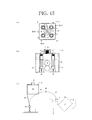
- FIG.15 is a schematic diagram illustrating the space debris removing device according to a fifth embodiment of the present invention, (a) illustrates a rear view, (b) illustrates a B-B cross sectional view in FIG.15(a), and (c) illustrates a schematic diagram illustrating the using state.
- FIG.16 is a schematic diagram illustrating the space debris removing device according to a sixth embodiment of the present invention, (a) illustrates a rear view, (b) illustrates a B-B cross sectional view in FIG.16(a), and (c) illustrates a schematic diagram illustrating the using state.
- the same signs are attached to the same components as the space debris removing device 2 according to the first to third embodiments and redundant descriptions will be omitted.
- the deceleration device 6 is externally attached to the surface (back surface part) of the body part 21.
- the deceleration device 6 By disposing the deceleration device 6 outside the body part 21, a free space can be secured inside the body part 21, and the plurality of harpoons 41 can be mounted by utilizing the free space. That is, the plurality of capture devices 4 may be disposed in the body part 21.
- the capture devices 4 may be disposed at four parts on diagonal lines as illustrated in FIG.14(a) , may be disposed at two parts on one diagonal line, may be disposed at three parts configuring vertexes of a triangle, or may be disposed at two parts in parallel.
- the capture devices 4 (harpoons 41) be redundant in such a manner, even when the first harpoon 41 is not pierced to the target debris 1, the harpoon 41 can be ejected again to capture the target debris 1, and redundancy of a capture function can be improved.
- the propulsion device 3 (the main direction thruster 31, the side thruster 32, the thruster 33 for the attitude control) is used to change a direction of the body part 21, the deceleration device 6 is discharged from the body part 21, and the conductive tether 61 is expanded in space.
- the deceleration device 6 configures the distal end part 62 which is a storage part of the conductive tether 61 and also has propulsion power.
- the conductive tether 61 can be expanded into a desired state.
- the deceleration device 6 is externally attached to the surface of the body part 21, and the body part 21 is utilized as the distal end part 62 of the deceleration device 6.
- the wire 46 of the capture device 4 is connected with a rear end of the conductive tether 61 through a connector 63, and the conductive tether 61 and the connector 63 may be accommodated inside the deceleration device 6 fixed to the back surface part of the body part 21.
- the space debris removing device 2 has the connector 63 for connecting the conductive tether 61 and the wire 46, and the distal end part 62 is constituted of the body part 21.
- the wire 46 may be extended to the deceleration device 6 at the back surface part along an outer edge part of the body part 21.
- the connector 63 is constituted of an electrical insulator so that static electricity or the like generated by the contact of the harpoon 41 and the target debris 1 is not transmitted to the conductive tether 61.
- the plurality of capture devices 4 may be disposed in the body part 21 similarly to the fourth embodiment.
- the propulsion device 3 (the main direction thruster 31, the side thruster 32, the thruster 33 for the attitude control) is used to change a direction of the body part 21, the body part 21 is moved in a direction in which the conductive tether 61 is desired to be expanded (for instance, a direction toward the earth) as needed while discharging the connector 63 and the conductive tether 61 from the deceleration device 6 or the body part 21, and the deceleration device 6 is separated and cut off from the body part 21.
- attitude controllable thrust generation means may be mounted in the deceleration device 6 to change the direction or the like by itself after separating the deceleration device 6 from the body part 21.
- the conductive tether 61 may be expanded into the desired state by moving the body part 21 in the direction in which the conductive tether 61 is desired to be expanded (for instance, the direction toward the earth) while discharging the connector 63 and the conductive tether 61 from the deceleration device 6 or the body part 21.
- the body part 21 can be used as the distal end part 62 of the deceleration device 6, and the configuration of the deceleration device 6 can be simplified.
- the deceleration device 6 is externally attached to the surface of the body part 21, the body part 21 is utilized as the distal end part 62 of the deceleration device 6, and a part of the deceleration device 6 is configured so as to be separated from the body part 21.
- the deceleration device 6 illustrated in the fifth embodiment is divided into a plurality of devices that are a first deceleration device 6a, a second deceleration device 6b, a third deceleration device 6c and a fourth deceleration device 6d, and the first deceleration device 6a to the fourth deceleration device 6d are configured so as to be separated (cut off) from the body part 21 individually. It is preferable that a division number of the deceleration device 6 is set so as to be in one-to-one correspondence with the capture devices 4 (harpoons 41).
- the propulsion device 3 (the main direction thruster 31, the side thruster 32, the thruster 33 for the attitude control) is used to change the direction of the body part 21, the body part 21 is moved in a direction in which the conductive tether 61 is desired to be expanded (for instance, the direction toward the earth) as needed while discharging the connector 63 and the conductive tether 61 from the deceleration device 6 (for instance, the first deceleration device 6a), and the first deceleration device 6a is separated and cut off from the body part 21.
- attitude controllable thrust generation means may be mounted in the first deceleration device 6a to change the direction or the like by itself after separating the first deceleration device 6a from the body part 21.
- the space debris removing device 2 moves toward the next target debris 1 by using the propulsion device 3.
- the space debris removing device 2 may be moved toward the next target debris 1 by separating and cutting off the first deceleration device 6a from the body part 21 after the conductive tether 61 is expanded by the space debris removing device 2.
- the present invention is not limited to the above-described embodiments and is, of course, variously changeable in the range of not deviating from the purpose of the present invention.
Landscapes
- Engineering & Computer Science (AREA)
- Remote Sensing (AREA)
- Aviation & Aerospace Engineering (AREA)
- General Physics & Mathematics (AREA)
- Astronomy & Astrophysics (AREA)
- Physics & Mathematics (AREA)
- Radar, Positioning & Navigation (AREA)
- Combustion & Propulsion (AREA)
- Chemical & Material Sciences (AREA)
- Life Sciences & Earth Sciences (AREA)
- Geology (AREA)
- Geochemistry & Mineralogy (AREA)
- General Life Sciences & Earth Sciences (AREA)
- Environmental & Geological Engineering (AREA)
- Cleaning In General (AREA)
- Manipulator (AREA)
Abstract
Description
- The present invention relates to a space debris removing device and a space debris removing method, and relates in particular to a space debris removing device and a space debris removing method that are suitable for removing relatively large-sized space debris such as a used satellite or rocket orbiting the earth.
- Currently, satellites for various purposes, such as military satellites, communication satellites, scientific satellites, observation satellites and navigation satellites, are orbiting the earth. When the satellites fail and become non-functional or end their duty and reach the end of their service life, the satellites are often left in orbit as they are and become space debris. Also, wreckage of a rocket or the like used for launching a satellite or the like is also left in orbit as space debris. Currently, several thousand pieces of space debris or more are in orbit and a phase of self-reproduction in which the number of pieces is increased by natural collisions has started. In order to stop the self-reproduction of the space debris, at least about 5 pieces of space debris need to be removed yearly. Space debris is attracted by terrestrial gravitation, and falls and disappears eventually, however, a gravity fall requires many years and it is not efficient. So, a method for positively removing space debris is already proposed (for instance, see
Patent Document 1 and Patent Document 2). - In a space debris removing method described in
Patent Document 1, a pressure receiving device for receiving a fine amount of atmosphere and solar light radiation pressure is configured by a circular or polygonal film material, and by attaching the pressure receiving device to space debris already orbiting in space or a spacecraft to be launched hereafter through a string, an important orbit is protected by a fall to the ground or orbit change of the space debris or the spacecraft after use. For attachment of the pressure receiving device, a method of driving a harpoon or a method of attaching the pressure receiving device by a robot arm is used. - In a space debris removing method described in
Patent Document 2, a tether device for space debris orbit conversion including a conductive tether which is attached to space debris such as a broken satellite or satellite wreckage or the like and obtains force of changing the orbit of the space debris by electromagnetic interaction with a geomagnetic field is used, the tether device for the space debris orbit conversion includes a capture mechanism capable of gripping a structural part of the space debris and a tether mechanism connected to the capture mechanism and extensibly holding the tether, and after gripping the space debris by the capture mechanism, the tether is extended by the tether mechanism, the robot arm is detached, and the tether device for the space debris orbit conversion is dumped integrally with the space debris. -
- Patent Document 1: Japanese Patent Laid-Open No.
2010-285137 - Patent Document 2: Japanese Patent No.
3809524 - Now, the space debris is generally orbiting while undergoing an irregular rotating motion (tumbling motion). Therefore, how a deceleration device such as the pressure receiving device or a tether device is to be attached to such space debris undergoing the tumbling motion becomes a problem. In particular, when using a robot arm, it is needed to prevent the robot arm from colliding with the space debris, and control is complicated. However, this point is not sufficiently examined in the space debris removing methods described in
Patent Document 1 andPatent Document 2. - The present invention has been made in view of the problems, and has an object to provide a space debris removing device and a space debris removing method, capable of easily attaching a deceleration device to the space debris undergoing the tumbling motion.
- According to the present invention, a space debris removing device, which removes space debris undergoing an irregular tumbling motion from an orbit by capturing and decelerating the space debris, is provided including a propulsion device for performing approach and attitude control to target debris which is the space debris to be removed, a capture device having a harpoon which can be ejected toward the target debris, an observation device for observing a motion of the target debris and calculating a capture position and a capture attitude at which the harpoon can be driven into a hollow portion of the target debris, a deceleration device directly or indirectly connected to the harpoon, for decelerating the target debris, and a body part on which the propulsion device, the capture device, the observation device and the deceleration device are mounted.
- The harpoon may include a pointed end part having a barb part that can be locked to the target debris, a stopper part to be in contact with a surface of the target debris, a thrust generation part for ejecting the harpoon, and a wire for connecting the harpoon to the body part.
- The barb part may be configured so as to be closed when passing through the target debris and be opened after passing through the target debris.
- The harpoon may be configured such that an elastic body disposed so as to cover the pointed end part on a front surface of the stopper part is provided, and by compressing the elastic body between the target debris surface and the stopper part when the pointed end part is locked to the target debris, scattering of broken pieces generated when the harpoon passes through is suppressed.
- The plurality of pointed end parts may be disposed on a surface of the stopper part and each of the pointed end parts may be configured so as to be capable of being pulled in when abutted to a location at which the pointed end part cannot pass through the surface of the target debris.
- A wire winding device capable of winding the wire may be provided, and by winding the wire after locking the pointed end part to the target debris, the body part may be closely fitted to the target debris.
- A buffer material for mitigating an impact when closely fitting the body part to the target debris may be disposed at the body part.
- A plurality of binding legs turnably disposed at the body part may be provided, and after the body part is closely fitted to the target debris, the binding legs may be expanded to fix the body part to the target debris, and the motion of the target debris may be suppressed using the propulsion device.
- The plurality of capture devices may be disposed at the body part.
- The deceleration device may include a conductive tether to be discharged into space, and a distal end part disposed at a distal end of the conductive tether and provided with thrust generation means for generating thrust.
- The deceleration device may include a conductive tether to be discharged into space, a distal end part disposed at a distal end of the conductive tether and provided with thrust generation means for generating thrust, and a connector for connecting a rear end of the conductive tether to the wire, and the wire may be connected to the body part through the conductive tether and the distal end part.
- The conductive tether may be connected so as to be separated from the body part. Also, the distal end part may be configured by the body part.
- Also, according to the present invention, a space debris removing method, which removes the space debris undergoing an irregular tumbling motion from the orbit by capturing and decelerating the space debris, is provided including an orbit injecting process of injecting the space debris removing device onto the orbit of target debris which is the space debris to be removed, an approaching process of making the space debris removing device approach the target debris, an observing and moving process of observing a motion of the target debris after the space debris removing device reaches an observation position, calculating a capture position and a capture attitude at which a harpoon can be driven into the target debris, and moving the space debris removing device to the capture position and the capture attitude, a capturing process of driving the harpoon into the target debris and connecting the space debris removing device and the target debris, and a decelerating process of decelerating the target debris by the space debris removing device.
- The capturing process may include a closely fitting process of winding a wire connected to the harpoon after the harpoon is driven into the target debris, and closely fitting the space debris removing device to the target debris.
- The capturing process may include a binding process of expanding binding legs disposed to the space debris removing device and binding the target debris after the space debris removing device is closely fitted to the target debris, and a motion suppressing process of suppressing a motion of the target debris by a propulsion device disposed at the space debris removal device.
- The observing and moving process may calculate the capture position and the capture attitude so as to drive the harpoon into a hollow portion of the target debris.
- The decelerating process may be a process of decelerating the target debris by discharging a conductive tether from the space debris removing device into space.
- According to the space debris removing device and the space debris removing method of the present invention, by making the space debris removing device approach the target debris, calculating the capture position and the capture attitude at which the harpoon can be driven into the target debris, driving the harpoon and then decelerating the target debris, an orbit of the target debris is changed and the target debris can be made to fall down to the earth and disappear. Also, the harpoon can be driven from a position away from the target debris, and even when the target debris is undergoing the tumbling motion, the target debris can be captured in the state that the space debris removing device and the target debris do not collide, and the deceleration device can be easily attached.
- Also, by closely fitting the space debris removing device to the captured target debris, the wire connected to the harpoon is not easily wound around the target debris undergoing the tumbling motion, and an operation state of the deceleration device can be stabilized. Further, by fixing the space debris removing device to the target debris by the binding legs, the tumbling motion of the target debris can be suppressed using the propulsion device, and the operation state of the deceleration device can be stabilized more.
-
-
FIG.1 is an overall schematic diagram illustrating an orbit injecting process to a capturing process of the space debris removing method according to a first embodiment of the present invention. -
FIG.2 is an overall schematic diagram illustrating a decelerating process of the space debris removing method according to the first embodiment of the present invention. -
FIG.3 is a flowchart illustrating the space debris removing method according to the first embodiment of the present invention. -
FIG.4 is a flowchart illustrating a modification of the space debris removing method according to the first embodiment of the present invention. -
FIG.5 is a schematic diagram illustrating the space debris removing device according to the first embodiment of the present invention, (a) illustrates a front view, and (b) illustrates a B-B cross sectional view inFIG.5(a) . -
FIG.6 is a diagram illustrating a capture device, (a) illustrates an overall schematic diagram, (b) illustrates a perspective view of a harpoon, (c) illustrates a first modification of the harpoon, (d) illustrates a second modification of the harpoon, and (e) illustrates a third modification of the harpoon. -
FIG.7 is a diagram illustrating modifications of the harpoon, (a) illustrates a fourth modification, (b) illustrates a fifth modification, (c) illustrates a sixth modification, and (d) illustrates a seventh modification. -
FIG.8 is a diagram illustrating a storage state of the harpoon, (a) illustrates a schematic diagram when including a wire winding device, and (b) illustrates a schematic diagram when not including the wire winding device. -
FIG.9 is a schematic diagram illustrating the space debris removing device according to a second embodiment of the present invention, (a) illustrates a front view, (b) illustrates a B-B cross sectional view inFIG.9(a), and (c) illustrates a schematic diagram illustrating a using state. -
FIG.10 is a schematic diagram illustrating the space debris removing device according to a third embodiment of the present invention, (a) illustrates a cross sectional view, and (b) illustrates a front view. -
FIG.11 is a schematic diagram illustrating binding legs, (a) illustrates a first example, (b) illustrates a second example, and (c) illustrates a third example. -
FIG.12 is a flowchart illustrating a part of the space debris removing method according to the third embodiment of the present invention. -
FIG.13 is an overall schematic diagram illustrating the decelerating process of the space debris removing method according to the third embodiment of the present invention. -
FIG.14 is a schematic diagram illustrating the space debris removing device according to a fourth embodiment of the present invention, (a) illustrates a rear view, (b) illustrates a B-B cross sectional view inFIG.14(a), and (c) illustrates a schematic diagram illustrating the using state. -
FIG.15 is a schematic diagram illustrating the space debris removing device according to a fifth embodiment of the present invention, (a) illustrates a rear view, (b) illustrates a B-B cross sectional view inFIG.15(a), and (c) illustrates a schematic diagram illustrating the using state. -
FIG.16 is a schematic diagram illustrating the space debris removing device according to a sixth embodiment of the present invention, (a) illustrates a rear view, (b) illustrates a B-B cross sectional view inFIG.16(a), and (c) illustrates a schematic diagram illustrating the using state. - Hereinafter, embodiments of the present invention will be described using
FIG.1 to FIG.16 . Here,FIG.1 is an overall schematic diagram illustrating an orbit injecting process to a capturing process of the space debris removing method according to a first embodiment of the present invention.FIG.2 is an overall schematic diagram illustrating a decelerating process of the space debris removing method according to the first embodiment of the present invention.FIG.3 is a flowchart illustrating the space debris removing method according to the first embodiment of the present invention.FIG.4 is a flowchart illustrating a modification of the space debris removing method according to the first embodiment of the present invention. - The space debris removing method according to the first embodiment of the present invention is for removing space debris undergoing an irregular tumbling motion from an orbit by capturing and decelerating the space debris as illustrated in
FIG.1 to FIG.3 , and includes: an orbit injecting process (Step 1) of injecting a spacedebris removing device 2 around an orbit L oftarget debris 1 which is the space debris to be removed; an approaching process (Steps 2, 3) of making the spacedebris removing device 2 approach thetarget debris 1; an observing and moving process (Steps 4-7) of observing a motion of thetarget debris 1 after the spacedebris removing device 2 reaches an observation position T, calculating a capture position E and a capture attitude at which aharpoon 41 can be driven into thetarget debris 1, and moving the spacedebris removing device 2 to the capture position E and the capture attitude; a capturing process (Step 8) of driving theharpoon 41 into thetarget debris 1 and connecting the spacedebris removing device 2 and thetarget debris 1; and a decelerating process (Step 9) of decelerating thetarget debris 1 by the spacedebris removing device 2. - The
target debris 1 is, as illustrated inFIG.1 , irregularly rotating while orbiting on the orbit L. That is, thetarget debris 1 is orbiting on the orbit L while undergoing an irregular tumbling motion. Therefore, when attaching a deceleration device by a robot arm, a driving timing and a driving direction of the robot arm need to be controlled so that the robot arm does not collide with thetarget debris 1, and calculation and control become complicated. On the other hand, in the present invention, collision of thetarget debris 1 and the spacedebris removing device 2 can be suppressed since thetarget debris 1 is captured by driving theharpoon 41 from the capture position E at which the spacedebris removing device 2 does not collide with thetarget debris 1. - The orbit injecting process (Step 1) is the process of disposing the launched space
debris removing device 2 around the orbit L of thetarget debris 1. Specifically, the spacedebris removing device 2 is injected into a range from which the spacedebris removing device 2 can reach the orbit L by itself. For instance, the spacedebris removing device 2 is injected to a position lower than the orbit L, and gradually approaches the orbit L by centrifugal force while approaching thetarget debris 1 by using a propulsion device. - The space
debris removing device 2 is in a shape of a small-sized satellite having the size of about several tens cm to several m, for instance, and may be launched alone from the earth or may be launched in the form of sharing a ride with a main satellite as a piggy bag satellite. Thetarget debris 1 which is to be removed is basically set beforehand, the orbit L is measured from the earth, and the spacedebris removing device 2 is launched so as to be injected around the orbit L. Adjustment in orbit injection is processed by the propulsion device mounted in the spacedebris removing device 2 on the basis of information of GPS (Global Positioning System). - The approaching process (
Steps 2, 3) is the process of making the spacedebris removing device 2 approach the observation position T of thetarget debris 1. The observation position T is, for instance, set at a position about 30-500 m away from thetarget debris 1 on the orbit L. The spacedebris removing device 2 moves from an injection position S to the observation position T while recognizing a position of the device itself and a position of thetarget debris 1 by using the GPS or the like. At the time, the spacedebris removing device 2 checks whether or not the observation position T is reached (Step 2), approaches the target debris 1 (Step 3) when the observation position T is not reached (N), and advances to the next process when the observation position T is reached (Y). - The observing and moving process (Steps 4-7) is the process of making the space
debris removing device 2 approach the capture position E of thetarget debris 1. The spacedebris removing device 2 which reaches the observation position T observes thetarget debris 1 by an observer such as a CCD camera or a laser radar (Step 4), and estimates a motion model of thetarget debris 1. By the estimated result, the capture position E and the capture attitude for driving theharpoon 41 to thetarget debris 1 are calculated (Step 5). The capture position E is a position at which thetarget debris 1 undergoing the tumbling motion and the spacedebris removing device 2 do not collide for instance, and is set at a position about several m to several tens m away from thetarget debris 1. The capture position E may be a position off the orbit L of thetarget debris 1. The capture attitude means a state of being set to a direction from which theharpoon 41 can be driven into a part where theharpoon 41 is desired to be driven into thetarget debris 1. - Also, the space
debris removing device 2 may calculate the capture position E and the capture attitude so as to drive theharpoon 41 into a hollow portion such as a tank 11 of thetarget debris 1. By driving theharpoon 41 into the hollow portion such as the tank 11, theharpoon 41 can be easily locked to thetarget debris 1. Also, the capture position E and the capture attitude may be such a position and attitude that theharpoon 41 can be substantively vertically driven into the surface of thetarget debris 1, or may be such a position and attitude that theharpoon 41 can be driven into a position with little fluctuation such as a fixed point in the estimated motion model of thetarget debris 1. - After the capture position E and the capture attitude are calculated, the space
debris removing device 2 autonomously moves to the capture position E and the capture attitude using the propulsion device. At the time, the spacedebris removing device 2 checks whether or not the capture position/attitude are reached (Step 6), moves toward the capture position E and the capture attitude (Step 7) when the capture position E and the capture attitude are not reached (N), and advances to the next process when the capture position E and the capture attitude are reached(Y). - The capturing process (Step 8) is the process of driving the
harpoon 41 into thetarget debris 1 and capturing thetarget debris 1. Theharpoon 41 is connected with the spacedebris removing device 2 by awire 46, and when theharpoon 41 is locked to thetarget debris 1, the state that thetarget debris 1 and the spacedebris removing device 2 are connected by thewire 46 is attained. By adopting a system of capturing thetarget debris 1 by driving theharpoon 41 in such a manner, in the state of disposing the spacedebris removing device 2 at a position and an attitude (the capture position E and the capture attitude) for not colliding with thetarget debris 1 undergoing the tumbling motion, theharpoon 41 can be driven so as not to collide with thetarget debris 1. Thus, compared to other systems (for instance, the system of performing gripping by a robot arm), a mechanism and calculation for determining the capture position E and the capture attitude can be simplified or saved in terms of labor, a performance demanded for an observation/capture mechanism of the spacedebris removing device 2 can be mitigated, processing burdens on a controller can be reduced, and thetarget debris 1 and the spacedebris removing device 2 can be easily connected. - The decelerating process (Step 9) is the process of decelerating the
target debris 1 by the spacedebris removing device 2 and accelerating or controlling a fall to the earth. The decelerating process is, for instance, the process of decelerating thetarget debris 1 by discharging aconductive tether 61 from the spacedebris removing device 2 into space. Means for decelerating thetarget debris 1 may be pressure receiving means which receives a radiation pressure of the solar wind or solar light or the like. - As illustrated in
FIG.2 , theconductive tether 61 may include adistal end part 62 disposed at a distal end and provided with thrust generation means for generating thrust. Since thedistal end part 62 includes the thrust generation means, theconductive tether 61 can be guided into a direction in which expansion is desired, and expansion of theconductive tether 61 can be stabilized. For the thrust generation means, a small-sized rocket motor, a cold gas jet using nitrogen or liquefied alternative fluorocarbon or the like, a monopropellant, electric propulsion of a pulsed plasma thruster, and a propulsion device utilizing a sublimate such as camphor or the like can be used. - By discharging the
conductive tether 61 from the spacedebris removing device 2, Lorentz force acts on theconductive tether 61 from relationship between a current flowing to theconductive tether 61 and a magnetic field where theconductive tether 61 is expanded, and theconductive tether 61 is pulled in a direction opposite to an advancing direction of thetarget debris 1, thereby decelerating thetarget debris 1. Therefore, by controlling a length of theconductive tether 61 and a size of the current, the fall of thetarget debris 1 can be accelerated or controlled. - In a flowchart illustrated in
FIG.4 , flow from orbit injection (Step 1) to reaching the observation position T (Step 2) is carried out stepwise. In order to observe the motion of thetarget debris 1 and estimate the motion model, an observer (for instance, a CCD camera or a laser radar or the like) capable of accurately recognizing the motion of thetarget debris 1 is required. In order to observe thetarget debris 1 by the observer, it is preferable to approach a position of about several tens m, for instance. Also, an injection position S at which the spacedebris removing device 2 is injected to the orbit is often a position at least several hundreds m to several thousands m away from thetarget debris 1, and a moving distance to the observation position T is long. At the beginning after the spacedebris removing device 2 is injected to the orbit, it is preferable to use a GPS in order to recognize its own position. However, it is difficult to accurately predict the position of thetarget debris 1 on the basis of normal observation data from the ground, and sometimes it is difficult to accurately guide the spacedebris removing device 2 to the observation position T. Then, when the spacedebris removing device 2 approaches thetarget debris 1, the observation position T may be reached while monitoring the position of thetarget debris 1 by itself. - Specifically, the space
debris removing device 2 has a monitoring device such as a laser radar mounted thereon, and the spacedebris removing device 2 checks whether or not a monitoring position at which the GPS is to be switched to the monitoring device is reached (Step 21), approaches thetarget debris 1 by using the GPS (Step 22) when the monitoring position is not reached (N), and switches from the GPS to monitoring of thetarget debris 1 by the monitoring device (Step 23) when the monitoring position is reached (Y). Thereafter, the spacedebris removing device 2 approaches while measuring a direction and a distance of thetarget debris 1 by the monitoring device, and advances to the next process (Step 2). Also, the processes after theStep 2 are the same as in a flowchart illustrated inFIG.3 . - Next, the space debris removing device according to the first embodiment of the present invention will be described. Here,
FIG.5 is a schematic diagram illustrating the space debris removing device according to the first embodiment of the present invention, (a) illustrates a front view, and (b) illustrates a B-B cross sectional view inFIG.5(a) .FIG.6 is a diagram illustrating a capture device, (a) illustrates an overall diagram, (b) illustrates a perspective view of a harpoon, (c) illustrates a first modification of the harpoon, (d) illustrates a second modification of the harpoon, and (e) illustrates a third modification of the harpoon.FIG.7 is a diagram illustrating modifications of the harpoon, (a) illustrates a fourth modification, (b) illustrates a fifth modification, (c) illustrates a sixth modification, and (d) illustrates a seventh modification.FIG.8 is a diagram illustrating a storage state of the harpoon, (a) illustrates a schematic diagram when including a wire winding device, and (b) illustrates a schematic diagram when not including the wire winding device. - The space
debris removing device 2 according to the first embodiment of the present invention is, as illustrated inFIG.5 , the space debris removing device which removes space debris undergoing an irregular tumbling motion from an orbit by capturing and decelerating the space debris, and includes: apropulsion device 3 for performing approach and attitude control to the target debris 1 (seeFIG.1 ) which is the space debris to be removed; acapture device 4 having theharpoon 41 which can be ejected toward thetarget debris 1; an observation device 5 for observing a motion of thetarget debris 1 and calculating the capture position E and the capture attitude at which theharpoon 41 can be driven into a hollow portion such as the tank 11 of thetarget debris 1; adeceleration device 6 directly or indirectly connected to theharpoon 41, for decelerating thetarget debris 1; abody part 21 on which thepropulsion device 3, thecapture device 4, the observation device 5 and thedeceleration device 6 are mounted; and apower supply device 7 charged by asolar battery panel 71 disposed on an outer surface of thebody part 21, for supplying power to devices mounted in thebody part 21. - The
propulsion device 3 is a device used for the approach to thetarget debris 1 of the space debris removing device 2 (the body part 21), movement to the capture position E and the capture attitude, and attitude control of thebody part 21, etc. Specifically, thepropulsion device 3 includes, for instance, amain direction thruster 31 described inFIG.5(b) , aside thruster 32 and athruster 33 for the attitude control described inFIG.5(a) , and apropellant tank 34 for generating a gas to be jetted from the thrusters, etc. The configuration of thepropulsion device 3 is just an example, and is not limited to the configuration illustrated in the figure. - The
capture device 4 is a device which has theharpoon 41 that can be ejected from alauncher 42 formed or installed at thebody part 21 and connects thetarget debris 1 and the space debris removing device 2 (the body part 21). Theharpoon 41 includes, as described inFIG.5(b) andFIGS.6(a) and (b) , apointed end part 43 having abarb part 43a that can be locked to thetarget debris 1, astopper part 44 to be in contact with the surface of thetarget debris 1, athrust generation part 45 for ejecting theharpoon 41, and thewire 46 for connecting theharpoon 41 to thebody part 21. Also, thecapture device 4 may include an ejecting direction adjusting mechanism (for instance, a gimbal mechanism or the like) for adjusting or finely adjusting an ejecting direction of theharpoon 41. - The
pointed end part 43 is constituted of a metal having strength enough to pass through the surface of thetarget debris 1, and has a pointed distal end. Thebarb part 43a may be constituted of a back surface of a plurality of triangular blade members formed on a side face of thepointed end part 43 or may be constituted of a conical bottom surface part. - The
stopper part 44 is for regulating theharpoon 41 so as not to pass through thetarget debris 1. When theharpoon 41 passes through the front and back of thetarget debris 1, there is the possibility of generating extra broken pieces (debris) when theharpoon 41 gets off to the outside. Also, in the case that an oxidizing agent remains when theharpoon 41 reaches an oxidizing agent tank inside thetarget debris 1, there is the possibility of causing an explosion. Then, in order to lock theharpoon 41 to the surface of thetarget debris 1, for instance, theharpoon 41 is driven toward the tank 11 (hollow portion) such as a fuel tank or an empty oxidizing agent tank, and thestopper part 44 is formed at theharpoon 41. - The
thrust generation part 45 is for adding thrust to theharpoon 41. Thethrust generation part 45 is constituted of a rocket motor with solid propellant or the like, for instance. Also, thelauncher 42 has a hollow passing through thebody part 21, and is configured such that, when thethrust generation part 45 is operated, the reaction is not easily added to thebody part 21. Thelauncher 42 is not necessarily required to be built in thebody part 21 and may be configured so as to be externally attached to the surface of thebody part 21. - The
wire 46 is a member for connecting theharpoon 41 and thebody part 21, and is the member for connecting thetarget debris 1 and the body part 21 (the space debris removing device 2) by theharpoon 41 locked to thetarget debris 1. Thewire 46 has a length of several m to several tens m, for instance, and when theharpoon 41 is stored, is turned to the state of being wound to awire drum 46a to suppress the fall of theharpoon 41. When ejecting theharpoon 41, thewire 46 is delivered from thewire drum 46a accompanying the advance of theharpoon 41. Also, theharpoon 41 may be locked to thelauncher 42 by a shear pin or a retractable stopper to perform positioning or suppress the fall. - Here, modifications of the
harpoon 41 will be described. The first modification of theharpoon 41 illustrated inFIG.6(c) includes a cylindrical body 47 (elastic body) disposed so as to cover an outer periphery of thepointed end part 43 on a front surface of thestopper part 44, and is configured to form a closed space by compressing thecylindrical body 47 between the surface of thetarget debris 1 and thestopper part 44 when thepointed end part 43 is locked to thetarget debris 1. Thecylindrical body 47 has a bellows structure, for instance. By disposing thecylindrical body 47, scattering of broken pieces such as heat insulating material generated when theharpoon 41 passes through can be suppressed. Thecylindrical body 47 is configured into a substantively cylindrical shape for instance, but may be configured into a truncated conical cylindrical shape in which the diameter of a distal end side is enlarged. - The second modification of the
harpoon 41 illustrated inFIG.6(d) includes a fiber body 47' (elastic body) disposed so as to cover thepointed end part 43 on the front surface of thestopper part 44, and is configured to suppress scattering of broken pieces generated when theharpoon 41 passes through by compressing the fiber body 47' (elastic body) between the surface of thetarget debris 1 and thestopper part 44 when thepointed end part 43 is locked to thetarget debris 1. As the fiber body 47', when the coarse one is used, the broken pieces to scatter can be entwined and caught by the fiber body 47', and when the fine one is used, the broken pieces to scatter can be held between the fiber body 47' and the surface of thetarget debris 1. Light and strong aramid fibers or the like are formed into a sponge shape for the fiber body 47', for instance, and the elastic body may be a resin like sponge or a metal such as steel wool, instead of the fiber body 47'. - In the third modification of the
harpoon 41 illustrated inFIG.6(e) , thebarb part 43a of thepointed end part 43 is configured so as to be closed when passing through thetarget debris 1 and be opened after passing through thetarget debris 1. In the third modification, thebarb part 43a is constituted of a leaf spring member, for instance, and is configured so as to be extended and contracted in a radial direction of theharpoon 41. In order to strengthen restoration force of thebarb part 43a, the elastic body of rubber or a coil spring or the like may be disposed. Also, an opening/closing mechanism of thebarb part 43a is just an example, and is not limited to the configuration illustrated in the figure. - In the fourth modification of the
harpoon 41 illustrated inFIG.7(a) , the plurality ofpointed end parts 43 are disposed on the surface of thestopper part 44. While one pointedend part 43 is disposed in theharpoon 41 illustrated inFIG.6(b) , three pointedend parts 43 are disposed in theharpoon 41 illustrated inFIG.7(a) . Also, on an outer periphery of thepointed end parts 43, thecylindrical body 47 may be disposed as illustrated in the figure. - The fifth to seventh modifications of the
harpoon 41 illustrated inFIGS.7(b)-(d) assume the case that, in theharpoon 41 including the plurality ofpointed end parts 43, a part of theharpoon 41 is driven into a hard part (for instance, a part where arib 12 configuring a reinforcing part of thetarget debris 1 is formed) of thetarget debris 1. Specifically, the respectivepointed end parts 43 in the fifth to seventh modifications are configured so as to be capable of being pulled in when the surface of thetarget debris 1 cannot be passed through. By adopting the system, since the need of aiming at a harpoon driving position of thetarget debris 1 undergoing the tumbling motion avoiding the hard part such as a beam of a truss structure is eliminated, a mechanism and calculation for determining the capture position E and the capture attitude can be simplified or saved in terms of labor, the performance demanded for an observation/capture mechanism of the spacedebris removing device 2 can be mitigated, the processing burdens on a controller can be reduced, and thetarget debris 1 and the spacedebris removing device 2 can be easily connected. - In the fifth modification of the
harpoon 41 illustrated inFIG.7(b) , thepointed end part 43 is fixed to thestopper part 44 by ashear pin 43b to be broken when a fixed pressure is loaded. At thestopper part 44, a space (astorage part 44a) capable of storing thepointed end part 43 including thebarb part 43a is formed. Shear force of theshear pin 43b is adjusted so as not to be broken when thepointed end part 43 collides with a plate part of thetarget debris 1 and so as to be broken when thepointed end part 43 collides with the hard part of thetarget debris 1. - In the sixth modification of the
harpoon 41 illustrated inFIG.7(c) , the respectivepointed end parts 43 are configured to be capable of being pulled in by agas cylinder 44b. The respectivepointed end parts 43 are supported through apiston 43c inserted into thegas cylinder 44b. By the configuration, thepointed end parts 43 can be pulled in by utilizing compressibility of a gas. As illustrated in the figure, by configuring thegas cylinder 44b so as to communicate cylinder parts corresponding to the respectivepointed end parts 43, by the gas compressed by a certainpointed end part 43, the otherpointed end part 43 can be energized to the front. Also, thegas cylinder 44b may be disposed individually for the respectivepointed end parts 43. - In the seventh modification of the
harpoon 41 illustrated inFIG.7(d) , the respectivepointed end parts 43 are configured to be capable of being pulled in by acoil spring 43d. Elastic force of thecoil spring 43d is adjusted so as not to be compressed when thepointed end part 43 collides with a plate part of thetarget debris 1 and so as to be compressed when thepointed end part 43 collides with the hard part of thetarget debris 1. Instead of thecoil spring 43d, the elastic body of rubber or the like may be used. - The observation device 5 includes, for instance, an
observer 51 disposed at a front part of thebody part 21, and anoperation part 52 for detecting the relative position and attitude of thetarget debris 1 and thebody part 21 from video images or images or the like obtained by theobserver 51, estimating the motion model of thetarget debris 1 from time series information of the position and the attitude, and calculating the capture position E and the capture attitude. Theobserver 51 is constituted of a CCD camera or a laser radar or the like capable of acquiring the tumbling motion of thetarget debris 1 as the video image or the image or the like. Theoperation part 52 is constituted of an arithmetic processing unit such as a CPU, and may include a storage device for recording the video images or the images or the like of theobserver 51. Theoperation part 52 may be constituted of a part of a controller (not shown in the figure) of the spacedebris removing device 2. The controller operates thepropulsion device 3 on the basis of an operation result of the observation device 5, makes thebody part 21 be moved to the capture position E, and adjusts an ejecting direction (capture attitude) of theharpoon 41. Also, when thecapture device 4 includes the ejecting direction adjusting mechanism, rough positioning and attitude determination may be performed in thepropulsion device 3 and the ejecting direction of theharpoon 41 may be finely adjusted in the ejecting direction adjusting mechanism. - The
deceleration device 6 includes, for instance, theconductive tether 61 to be discharged into space, and thedistal end part 62 disposed at the distal end of theconductive tether 61 and provided with the thrust generation means for generating thrust. As described above, for the thrust generation means, a small-sized rocket motor, a cold gas jet, a one-liquid thruster, electric propulsion, and a sublimate or the like can be utilized. Theconductive tether 61 is, as illustrated in the figure, stored inside a case in a coil shape, and is configured so as to be loosened into a straight shape by discharging thedistal end part 62. Thedeceleration device 6 may be stored inside thebody part 21 or may be attached externally to the surface of thebody part 21. - The
power supply device 7 includes, for instance, thesolar battery panel 71 disposed on the outer surface of thebody part 21, and abattery 72 for storing electricity generated by thesolar battery panel 71. The electricity charged to thebattery 72 supplies power to devices requiring the power such as thepropulsion device 3, thecapture device 4, the observation device 5 and thedeceleration device 6 as needed through the controller. - The
body part 21 is constituted of a housing similar to a so-called small-sized satellite. Other than thepropulsion device 3, thecapture device 4, the observation device 5, thedeceleration device 6 and thepower supply device 7, thebody part 21 may have a monitoring device 22 such as a laser radar, a GPS sensor, a gyro, and an acceleration sensor or the like mounted thereon. Also, though not shown in the figure, the outer periphery of thebody part 21 is covered with a heat insulating material. - Incidentally, the
capture device 4 may include awire winding device 48 capable of winding thewire 46, as illustrated inFIG.8(a) . Thewire winding device 48 includes, for instance, anelectric motor 48a for generating motive power, a belt driving mechanism (atiming belt 48b and apulley 48c) for transmitting the motive power of theelectric motor 48a to awire drum 46a, acontrol part 48d for controlling the motive power of theelectric motor 48a, and alevel winding mechanism 48e for uniformly winding thewire 46. When ejecting theharpoon 41, it is preferable to interrupt power supply to theelectric motor 48a and a drive shaft is turned to a freely rotatable state. Also, a power transmission mechanism is not limited to the belt driving mechanism, and may be constituted of a gear train. - By disposing the
wire winding device 48, thebody part 21 can be closely fitted to thetarget debris 1 by winding thewire 46 after locking thepointed end part 43 to thetarget debris 1. Also, since there is the possibility that thewire 46 is entangled with thetarget debris 1 if thewire 46 is loosened between thetarget debris 1 and the spacedebris removing device 2, thewire winding device 48 may be operated so as to load thewire 46 with fixed tension and maintain a straight tense state. - When winding of the
wire 46 is not needed, as illustrated inFIG.8(b) , thewire winding device 48 may be omitted. In order to stabilize rewinding of thewire 46 from thewire drum 46a, thelevel winding mechanism 48e may be disposed. Also, thewire 46 may be not only wound around thewire drum 46a but also wound around a rear end part of theharpoon 41. Further, when the length of thewire 46 is short, thewire drum 46a may be omitted. When winding thewire 46 around the rear end part of theharpoon 41, it is preferable to wind thewire 46 from the front to the back for instance so that thewire 46 is smoothly loosened when ejecting theharpoon 41. - Next, the space
debris removing device 2 according to other embodiments of the present invention will be described with reference toFIG.9 to FIG.11 . Here,FIG.9 is a schematic diagram illustrating the space debris removing device according to a second embodiment of the present invention, (a) illustrates a front view, (b) illustrates a B-B cross sectional view inFIG.9(a), and (c) illustrates a schematic diagram illustrating a using state.FIG.10 is a schematic diagram illustrating the space debris removing device according to a third embodiment of the present invention, (a) illustrates a cross sectional view, and (b) illustrates a front view.FIG.11 is a schematic diagram illustrating binding legs, (a) illustrates a first example, (b) illustrates a second example, and (c) illustrates a third example. The same signs are attached to the same components as the spacedebris removing device 2 according to the first embodiment and redundant descriptions will be omitted. - In the space
debris removing device 2 according to the second embodiment illustrated inFIGS.9(a) and (b) , anannular buffer material 23 is disposed at the front part of thebody part 21. Thebuffer material 23 is formed of a metal such as an aluminum honeycomb or a resin such as urethane rubber. By the configuration, as illustrated inFIG.9(c) , when closely fitting thebody part 21 to thetarget debris 1 by winding thewire 46 after locking theharpoon 41 to thetarget debris 1, an impact when thebody part 21 collides with thetarget debris 1 can be mitigated, and breakage of thetarget debris 1 and a fault of the spacedebris removing device 2 can be suppressed. - Also, by the configuration, the space
debris removing device 2 can be closely fitted to thetarget debris 1 even when a surface shape of thetarget debris 1 is a complicated shape, strict position/speed control is not required when closely fitting the spacedebris removing device 2 to thetarget debris 1 undergoing the tumbling motion, position/speed control loads when performing close fitting can be mitigated, a mechanism and calculation for determining a position/attitude/speed for performing close fitting can be simplified or saved in terms of labor, the performance demanded for an observation/capture mechanism of the spacedebris removing device 2 can be mitigated, the processing burdens on the controller can be reduced, and thetarget debris 1 and the spacedebris removing device 2 can be easily connected. The configuration of thebuffer material 23 is not limited to the one illustrated in the figure, and may be a rectangular ring shape or the configuration of being distributed and disposed at the front part of thebody part 21. - The space
debris removing device 2 according to the third embodiment illustrated inFIGS.10(a) and (b) includes a plurality ofbinding legs 24 turnably disposed at thebody part 21, and after thebody part 21 is closely fitted to thetarget debris 1, the bindinglegs 24 are expanded to fix thebody part 21 to thetarget debris 1, and the motion of thetarget debris 1 is suppressed using thepropulsion device 3. The state of closing the bindinglegs 24 is illustrated inFIG.10(a) , and the state of opening thebinding legs 24 is illustrated inFIG.10(b) . By the configuration, the irregular tumbling motion of thetarget debris 1 can be suppressed by the bindinglegs 24 and thepropulsion device 3, and the deceleration device can be used in a stable state. Especially, when theconductive tether 61 is used as thedeceleration device 6, theconductive tether 61 can be prevented from moving wildly or getting entangled. - Also, by the configuration, the space
debris removing device 2 can be bound to thetarget debris 1 even when the surface shape of thetarget debris 1 is a complicated shape, and since the degree of freedom of a position to be connected to thetarget debris 1 undergoing the tumbling motion (that is, a harpoon driving position) is increased, a mechanism and calculation for determining the capture position E and the capture attitude can be simplified or saved in terms of labor, the performance demanded for an observation/capture mechanism of the spacedebris removing device 2 can be mitigated, the processing burdens on the controller can be reduced, and thetarget debris 1 and the spacedebris removing device 2 can be easily connected. InFIG.10(b) , figures of theside thruster 32 and thethruster 33 for the attitude control are omitted for convenience of descriptions. - The binding
legs 24 have a configuration illustrated inFIGS.11(a)-(c) for instance. In the respective figures, the figure of thebuffer material 23 is omitted. Also, the configurations of the first example to the third example of thebinding legs 24 are just examples, and not limited to the configurations. - In the first example illustrated in
FIG.11(a) , thebinding leg 24 is turned by anelectric motor 24a. Theelectric motor 24a has a brake function, and is configured to hold thebinding leg 24 in a stored state and an expanded state. Also, asensor 24b may be disposed at thebody part 21 and the distal end of thebinding leg 24 to sense the contact of thebody part 21 and thetarget debris 1, thereby operating theelectric motor 24a and expanding thebinding leg 24, and to sense the contact of thebinding leg 24 and thetarget debris 1, thereby stopping theelectric motor 24a and locking thebinding leg 24. Also, force may be continuously applied to thebinding leg 24 by theelectric motor 24a to fix thebody part 21 to thetarget debris 1. - In the second example illustrated in
FIG.11(b) , thebinding leg 24 is turned by acylinder 24c. Thecylinder 24c is pin-connected to thebinding leg 24 at a distal end and pin-connected to thebody part 21 at a rear end. Thecylinder 24c is a hydraulic cylinder, an air cylinder or an electric cylinder or the like for instance, and is configured so as to be extended and contracted. Also, thesensor 24b may be disposed at thebody part 21 and the distal end of thebinding leg 24 to sense the contact of thebody part 21 and thetarget debris 1, thereby extending thecylinder 24c and expanding thebinding leg 24, and to sense the contact of thebinding leg 24 and thetarget debris 1, thereby stopping the extension of thecylinder 24c and locking thebinding leg 24. Also, force may be continuously applied to thebinding leg 24 by thecylinder 24c to fix thebody part 21 to thetarget debris 1. - In the third example illustrated in
FIG.11(c) , thebinding leg 24 is turned by acoil spring 24d. Thecoil spring 24d is stored inside a container in the state of being compressed to energize adrive shaft 24e pin-connected to thebinding leg 24 at the distal end, and a closed state is kept by astopper 24f connected to thebody part 21 through a latch mechanism. When thesensor 24b senses the contact of thebody part 21 and thetarget debris 1, thestopper 24f is turned upwards, and thebinding leg 24 is expanded. In the third example, even when thebinding leg 24 is brought into contact with thetarget debris 1, force is continuously applied to thebinding leg 24 by thecoil spring 24d. - In the first example to the third example, while the
body part 21 is fixed to thetarget debris 1 by continuously applying force to thebinding leg 24, a locking part (for instance, a harpoon shape) to be pierced and locked to the surface of thebody part 21 may be formed at the distal end of thebinding leg 24, or an adhesion part to be bonded or fixed to the surface of thebody part 21 by applying or discharging an adhesive agent may be formed at the distal end of thebinding leg 24. Also, thebinding leg 24 is not limited to the configuration of a turning type, and may be the configuration of a fixing type formed so as to be brought into contact from thebody part 21 toward thetarget debris 1 or may have the locking part or the adhesion part formed at the distal end thereof, or the turning type and the fixing type may be used together. - The space debris removing method using the space
debris removing device 2 according to the third embodiment will be described. Here,FIG.12 is a flowchart illustrating a part of the space debris removing method according to the third embodiment of the present invention.FIG.13 is an overall schematic diagram illustrating the decelerating process of the space debris removing method according to the third embodiment of the present invention. - The flowchart illustrated in
FIG.12 illustrates the capturing process (Step 8) in detail. After the spacedebris removing device 2 reaches the capture position E and the capture attitude (Step 81), the spacedebris removing device 2 launches theharpoon 41 toward the target debris 1 (Step 82). The spacedebris removing device 2 checks whether or not theharpoon 41 is pierced to the target debris 1 (Step 83). Whether or not theharpoon 41 is pierced may be visually checked by theobserver 51 of the observation device 5 or may be checked by the tension of thewire 46. - When the
harpoon 41 is not pierced (N), whether or not there is aspare harpoon 41 is checked (Step 84). When there is no spare harpoon 41 (N), processing is ended due to a capture failure. When there is a spare harpoon 41 (Y), theharpoon 41 is launched again (Step 82). - When the
harpoon 41 is pierced (Y), thewire 46 is wound by the wire winding device 48 (Step 85), and the space debris removing device 2 (the body part 21) is closely fitted to the target debris 1 (Step 86). Thereafter, the spacedebris removing device 2 expands the binding legs 24 (Step 87) and binds thetarget debris 1. Then, by appropriately jetting themain direction thruster 31, theside thruster 32 and thethruster 33 for the attitude control of thepropulsion device 3, the motion of thetarget debris 1 is suppressed (Step 88). After the tumbling motion of thetarget debris 1 is calmed down, the process is shifted to the decelerating process (Step 9). - In the capturing process (Steps 81-88), for instance, when the space
debris removing device 2 does not include the bindinglegs 24 as in the second embodiment, the process may be stopped at a closely fitting process (Step 86) of closely fitting the spacedebris removing device 2 to thetarget debris 1 by winding thewire 46 connected to theharpoon 41 after driving theharpoon 41 into thetarget debris 1. Also, after checking that theharpoon 41 is pierced to the target debris 1 (Steps 83-84), the subsequent processes (Steps 85-88) may be omitted to shift to the decelerating process (Step 9). By omitting the processes (Steps 85-88), since the need of the process of closely fitting the spacedebris removing device 2 to thetarget debris 1 undergoing the tumbling motion is eliminated, position/speed control when performing close fitting can be omitted, the mechanism and calculation for determining the position/attitude/speed of the spacedebris removing device 2 can be simplified or saved in terms of labor, the performance demanded for an observation/capture mechanism of the spacedebris removing device 2 can be mitigated, and the processing burdens on the controller can be reduced. -
FIG.13 illustrates the state of discharging theconductive tether 61 in the decelerating process (Step 9) after suppressing the motion of thetarget debris 1 by the capturing process (Steps 81-88). In such a manner, by suppressing the motion of thetarget debris 1 by the bindinglegs 24 and thepropulsion device 3, theconductive tether 61 discharged into space is prevented from moving wildly or getting entangled, and a deceleration effect can be stably actuated. - Subsequently, the space
debris removing device 2 according to the other embodiments of the present invention will be described with reference toFIG.14 to FIG.16 . Here,FIG.14 is a schematic diagram illustrating the space debris removing device according to a fourth embodiment of the present invention, (a) illustrates a rear view, (b) illustrates a B-B cross sectional view inFIG.14(a), and (c) illustrates a schematic diagram illustrating the using state.FIG.15 is a schematic diagram illustrating the space debris removing device according to a fifth embodiment of the present invention, (a) illustrates a rear view, (b) illustrates a B-B cross sectional view inFIG.15(a), and (c) illustrates a schematic diagram illustrating the using state.FIG.16 is a schematic diagram illustrating the space debris removing device according to a sixth embodiment of the present invention, (a) illustrates a rear view, (b) illustrates a B-B cross sectional view inFIG.16(a), and (c) illustrates a schematic diagram illustrating the using state. The same signs are attached to the same components as the spacedebris removing device 2 according to the first to third embodiments and redundant descriptions will be omitted. - In the space
debris removing device 2 according to the fourth embodiment illustrated inFIGS.14(a) and (b) , thedeceleration device 6 is externally attached to the surface (back surface part) of thebody part 21. By disposing thedeceleration device 6 outside thebody part 21, a free space can be secured inside thebody part 21, and the plurality ofharpoons 41 can be mounted by utilizing the free space. That is, the plurality ofcapture devices 4 may be disposed in thebody part 21. For instance, thecapture devices 4 may be disposed at four parts on diagonal lines as illustrated inFIG.14(a) , may be disposed at two parts on one diagonal line, may be disposed at three parts configuring vertexes of a triangle, or may be disposed at two parts in parallel. By making the capture devices 4 (harpoons 41) be redundant in such a manner, even when thefirst harpoon 41 is not pierced to thetarget debris 1, theharpoon 41 can be ejected again to capture thetarget debris 1, and redundancy of a capture function can be improved. - In the space
debris removing device 2 according to the fourth embodiment, as illustrated inFIG.14(c) , after theharpoon 41 is locked to thetarget debris 1, the propulsion device 3 (themain direction thruster 31, theside thruster 32, thethruster 33 for the attitude control) is used to change a direction of thebody part 21, thedeceleration device 6 is discharged from thebody part 21, and theconductive tether 61 is expanded in space. In this embodiment, thedeceleration device 6 configures thedistal end part 62 which is a storage part of theconductive tether 61 and also has propulsion power. By the configuration, there is no need of disposing a complicated attitude control mechanism in thedeceleration device 6, and by setting a direction of discharging theconductive tether 61 by thebody part 21, cutting off thedeceleration device 6 from thebody part 21 and generating thrust, theconductive tether 61 can be expanded into a desired state. - In the space
debris removing device 2 according to the fifth embodiment illustrated inFIGS.15(a) and (b) , thedeceleration device 6 is externally attached to the surface of thebody part 21, and thebody part 21 is utilized as thedistal end part 62 of thedeceleration device 6. Specifically, thewire 46 of thecapture device 4 is connected with a rear end of theconductive tether 61 through aconnector 63, and theconductive tether 61 and theconnector 63 may be accommodated inside thedeceleration device 6 fixed to the back surface part of thebody part 21. That is, the spacedebris removing device 2 according to this embodiment has theconnector 63 for connecting theconductive tether 61 and thewire 46, and thedistal end part 62 is constituted of thebody part 21. Also, in the stored state of theharpoon 41, thewire 46 may be extended to thedeceleration device 6 at the back surface part along an outer edge part of thebody part 21. Theconnector 63 is constituted of an electrical insulator so that static electricity or the like generated by the contact of theharpoon 41 and thetarget debris 1 is not transmitted to theconductive tether 61. Also, the plurality ofcapture devices 4 may be disposed in thebody part 21 similarly to the fourth embodiment. - In the space
debris removing device 2 according to the fifth embodiment, as illustrated inFIG.15(c) , after theharpoon 41 is locked to thetarget debris 1, the propulsion device 3 (themain direction thruster 31, theside thruster 32, thethruster 33 for the attitude control) is used to change a direction of thebody part 21, thebody part 21 is moved in a direction in which theconductive tether 61 is desired to be expanded (for instance, a direction toward the earth) as needed while discharging theconnector 63 and theconductive tether 61 from thedeceleration device 6 or thebody part 21, and thedeceleration device 6 is separated and cut off from thebody part 21. Extension is accelerated by the thrust generation means disposed in thedeceleration device 6 and theconductive tether 61 is expanded into the desired state (for instance, the state of being extended in the direction toward the earth). Also, attitude controllable thrust generation means may be mounted in thedeceleration device 6 to change the direction or the like by itself after separating thedeceleration device 6 from thebody part 21. - When the
deceleration device 6 does not include the thrust generation means, theconductive tether 61 may be expanded into the desired state by moving thebody part 21 in the direction in which theconductive tether 61 is desired to be expanded (for instance, the direction toward the earth) while discharging theconnector 63 and theconductive tether 61 from thedeceleration device 6 or thebody part 21. By the configuration, thebody part 21 can be used as thedistal end part 62 of thedeceleration device 6, and the configuration of thedeceleration device 6 can be simplified. - In the space
debris removing device 2 according to the sixth embodiment illustrated inFIGS.16(a) and (b) , thedeceleration device 6 is externally attached to the surface of thebody part 21, thebody part 21 is utilized as thedistal end part 62 of thedeceleration device 6, and a part of thedeceleration device 6 is configured so as to be separated from thebody part 21. Specifically, thedeceleration device 6 illustrated in the fifth embodiment is divided into a plurality of devices that are afirst deceleration device 6a, asecond deceleration device 6b, athird deceleration device 6c and afourth deceleration device 6d, and thefirst deceleration device 6a to thefourth deceleration device 6d are configured so as to be separated (cut off) from thebody part 21 individually. It is preferable that a division number of thedeceleration device 6 is set so as to be in one-to-one correspondence with the capture devices 4 (harpoons 41). - In the space
debris removing device 2 according to the sixth embodiment, as illustrated inFIG.16(c) , after theharpoon 41 is locked to thetarget debris 1, the propulsion device 3 (themain direction thruster 31, theside thruster 32, thethruster 33 for the attitude control) is used to change the direction of thebody part 21, thebody part 21 is moved in a direction in which theconductive tether 61 is desired to be expanded (for instance, the direction toward the earth) as needed while discharging theconnector 63 and theconductive tether 61 from the deceleration device 6 (for instance, thefirst deceleration device 6a), and thefirst deceleration device 6a is separated and cut off from thebody part 21. Extension is accelerated by the thrust generation means disposed in thefirst deceleration device 6a and theconductive tether 61 is expanded into the desired state (for instance, the state of being extended in the direction toward the earth). Also, the attitude controllable thrust generation means may be mounted in thefirst deceleration device 6a to change the direction or the like by itself after separating thefirst deceleration device 6a from thebody part 21. - In the meantime, the space
debris removing device 2 moves toward thenext target debris 1 by using thepropulsion device 3. By the configuration, two or more pieces of thetarget debris 1 can be removed by one spacedebris removing device 2, and work efficiency can be improved. Also, when thefirst deceleration device 6a does not include the thrust generation means, the spacedebris removing device 2 may be moved toward thenext target debris 1 by separating and cutting off thefirst deceleration device 6a from thebody part 21 after theconductive tether 61 is expanded by the spacedebris removing device 2. - In the space
debris removing device 2 illustrated inFIG.14 to FIG.16 , figures are omitted for the detail of the observation device 5 and thepower supply device 7, etc., however, they are certainly configured so as to be stored inside thebody part 21 similarly to the first embodiment. - The present invention is not limited to the above-described embodiments and is, of course, variously changeable in the range of not deviating from the purpose of the present invention.
-
- 1 Target debris
- 2 Space debris removing device
- 3 Propulsion device
- 4 Capture device
- 5 Observation device
- 6 Deceleration device
- 7 Power supply device
- 11 Tank (hollow portion)
- 21 Body part
- 24 Binding leg
- 41 Harpoon
- 43 Pointed end part
- 43a Barb part
- 44 Stopper part
- 45 Thrust generation part
- 46 Wire
- 47 Cylindrical body (elastic body)
- 47' Fiber body (elastic body)
- 48 Wire winding device
- 61 Conductive tether
- 62 Distal end part
- 63 Connector
- 71 Solar battery panel
Claims (18)
- A space debris removing device which removes space debris undergoing an irregular tumbling motion from an orbit by capturing and decelerating the space debris, comprising:a propulsion device for performing approach and attitude control to target debris which is the space debris to be removed;a capture device having a harpoon which can be ejected toward the target debris;an observation device for observing a motion of the target debris and calculating a capture position and a capture attitude at which the harpoon can be driven into a hollow portion of the target debris;a deceleration device directly or indirectly connected to the harpoon, for decelerating the target debris; anda body part on which the propulsion device, the capture device, the observation device and the deceleration device are mounted.
- The space debris removing device according to claim 1, wherein the harpoon includes a pointed end part having a barb part that can be locked to the target debris, a stopper part to be in contact with a surface of the target debris, a thrust generation part for ejecting the harpoon, and a wire for connecting the harpoon to the body part.
- The space debris removing device according to claim 2, wherein the barb part is configured so as to be closed when passing through the target debris and be opened after passing through the target debris.
- The space debris removing device according to claim 2, wherein the harpoon includes an elastic body disposed so as to cover the pointed end part on a front surface of the stopper part, and by compressing the elastic body between the target debris surface and the stopper part when the pointed end part is locked to the target debris, scattering of broken pieces generated when the harpoon passes through is suppressed.
- The space debris removing device according to claim 2, wherein the plurality of pointed end parts are disposed on a surface of the stopper part and each of the pointed end parts is configured so as to be capable of being pulled in when abutted to a location at which the pointed end part cannot pass through the surface of the target debris.
- The space debris removing device according to claim 2, wherein a wire winding device capable of winding the wire is provided, and by winding the wire after locking the pointed end part to the target debris, the body part is closely fitted to the target debris.
- The space debris removing device according to claim 6, wherein a buffer material for mitigating an impact when closely fitting the body part to the target debris is disposed at the body part.
- The space debris removing device according to claim 6, wherein a plurality of binding legs turnably disposed at the body part are provided, and after the body part is closely fitted to the target debris, the binding legs are expanded to fix the body part to the target debris, and the motion of the target debris is suppressed using the propulsion device.
- The space debris removing device according to claim 1, wherein the plurality of capture devices are disposed at the body part.
- The space debris removing device according to claim 1, wherein the deceleration device includes a conductive tether to be discharged into space, and a distal end part disposed at a distal end of the conductive tether and provided with thrust generation means for generating thrust.
- The space debris removing device according to claim 2, wherein the deceleration device includes a conductive tether to be discharged into space, a distal end part disposed at a distal end of the conductive tether and provided with thrust generation means for generating thrust, and a connector for connecting a rear end of the conductive tether to the wire, and the wire is connected to the body part through the conductive tether and the distal end part.
- The space debris removing device according to claim 10 or claim 11,
wherein the conductive tether is connected so as to be separated from the body part. - The space debris removing device according to claim 10 or claim 11,
wherein the distal end part is configured by the body part. - A space debris removing method which removes space debris undergoing an irregular tumbling motion from an orbit by capturing and decelerating the space debris, comprising:an orbit injecting process of injecting a space debris removing device around an orbit of target debris which is the space debris to be removed;an approaching process of making the space debris removing device approach the target debris;an observing and moving process of observing a motion of the target debris after the space debris removing device reaches an observation position, calculating a capture position and a capture attitude at which a harpoon can be driven into the target debris, and moving the space debris removing device to the capture position and the capture attitude;a capturing process of driving the harpoon into the target debris and connecting the space debris removing device and the target debris; anda decelerating process of decelerating the target debris by the space debris removing device.
- The space debris removing method according to claim 14,
wherein the capturing process includes a closely fitting process of winding a wire connected to the harpoon after the harpoon is driven into the target debris, and closely fitting the space debris removing device to the target debris. - The space debris removing method according to claim 15,
wherein the capturing process includes a binding process of expanding binding legs disposed to the space debris removing device and binding the target debris after the space debris removing device is closely fitted to the target debris, and a motion suppressing process of suppressing a motion of the target debris by a propulsion device disposed at the space debris removal device. - The space debris removing method according to claim 14,
wherein the observing and moving process calculates the capture position and the capture attitude so as to drive the harpoon into a hollow portion of the target debris. - The space debris removing method according to claim 14,
wherein the decelerating process is a process of decelerating the target debris by discharging a conductive tether from the space debris removing device into space.
Applications Claiming Priority (2)
| Application Number | Priority Date | Filing Date | Title |
|---|---|---|---|
| JP2011241170 | 2011-11-02 | ||
| PCT/JP2012/078359 WO2013065795A1 (en) | 2011-11-02 | 2012-11-01 | Device for removing space debris and method for removing space debris |
Publications (3)
| Publication Number | Publication Date |
|---|---|
| EP2774855A1 true EP2774855A1 (en) | 2014-09-10 |
| EP2774855A4 EP2774855A4 (en) | 2015-08-12 |
| EP2774855B1 EP2774855B1 (en) | 2020-01-08 |
Family
ID=48192133
Family Applications (1)
| Application Number | Title | Priority Date | Filing Date |
|---|---|---|---|
| EP12844873.5A Active EP2774855B1 (en) | 2011-11-02 | 2012-11-01 | Device for removing space debris and method for removing space debris |
Country Status (5)
| Country | Link |
|---|---|
| US (1) | US9463884B2 (en) |
| EP (1) | EP2774855B1 (en) |
| JP (1) | JP5781623B2 (en) |
| CA (1) | CA2853892C (en) |
| WO (1) | WO2013065795A1 (en) |
Cited By (5)
| Publication number | Priority date | Publication date | Assignee | Title |
|---|---|---|---|---|
| EP3015369A1 (en) * | 2014-10-30 | 2016-05-04 | Airbus Defence and Space Limited | Space debris interception |
| EP3112274A1 (en) * | 2015-07-01 | 2017-01-04 | Thales | Spatial system for reducing the angular velocities of space debris before removing same from orbit |
| EP3360802A1 (en) * | 2017-02-09 | 2018-08-15 | Thales | Satellite with laser propulsion by ablation |
| CN109421942A (en) * | 2017-08-27 | 2019-03-05 | 南京乐朋电子科技有限公司 | Rotary and telescopic space trash recycles airship |
| CN118405277A (en) * | 2024-07-01 | 2024-07-30 | 浙大城市学院 | Space target rope net capturing device and method based on crisscross rope closing |
Families Citing this family (51)
| Publication number | Priority date | Publication date | Assignee | Title |
|---|---|---|---|---|
| ES2484845T3 (en) * | 2012-06-07 | 2014-08-12 | Astrium Limited | Space Object Capture |
| JP6051101B2 (en) * | 2013-05-20 | 2016-12-27 | 川崎重工業株式会社 | Space debris removal device fixing device using extension spring, and space debris removal device including the same |
| JP6245549B2 (en) * | 2013-05-20 | 2017-12-13 | 国立研究開発法人宇宙航空研究開発機構 | Device fixing device and device including the same |
| EP3056437A4 (en) * | 2013-10-07 | 2017-06-21 | Astroscale Japan Inc. | Rotation suppressing device |
| EP2860115A1 (en) * | 2013-10-11 | 2015-04-15 | Thales Alenia Space Deutschland GmbH | Method for modifying a position of uncontrolled objects in space and spacecraft for realizing the method |
| JP6472600B2 (en) * | 2014-03-18 | 2019-02-20 | 株式会社アストロスケール | Space device, debris removal system, and debris removal method |
| JP6473960B2 (en) * | 2014-06-13 | 2019-02-27 | 国立研究開発法人宇宙航空研究開発機構 | Space debris orbital descent method, orbital descent system, and satellite orbit conversion method, orbit conversion system |
| JP6429109B2 (en) * | 2014-09-30 | 2018-11-28 | 株式会社Ihi | Debris removing apparatus and debris removing method |
| WO2016063923A1 (en) * | 2014-10-24 | 2016-04-28 | 株式会社アストロスケール | Guidance method relating to non-cooperative approach |
| FR3029615B1 (en) * | 2014-12-05 | 2018-01-05 | Thales | DEVICE FOR LAUNCHING A PROJECTILE BY COMPRESSED FLUID |
| JP6525595B2 (en) * | 2015-01-09 | 2019-06-05 | キヤノン電子株式会社 | Space float capture system |
| AT517928A2 (en) * | 2015-11-06 | 2017-05-15 | Keba Ag | Control system for electrically controlled systems |
| RU2626788C2 (en) * | 2015-12-23 | 2017-08-01 | Федеральное государственное бюджетное образовательное учреждение высшего образования Московский авиационный институт (национальный исследовательский университет) (МАИ) | Descent tow vehicle for retrieving space objects from orbits |
| JP6472772B2 (en) * | 2016-05-30 | 2019-02-20 | 株式会社アストロスケール | Object removal method, transport method and control method |
| CN106467178B (en) * | 2016-09-19 | 2018-11-02 | 哈尔滨工业大学 | Whisker adhesion type large-size space non-cooperative target rapid racemization processing bag |
| US9714101B1 (en) * | 2016-10-25 | 2017-07-25 | Marshall H. Kaplan | Apparatus and methods for orbital debris removal |
| FR3058393A1 (en) * | 2016-11-10 | 2018-05-11 | Airbus Defence And Space Sas | SPACE ENGINE COMPRISING MEANS OF ATTITUDE ACTIVE MONITORING AND PASSIVE ATTITUDE CONTROL MEANS |
| KR101815922B1 (en) | 2016-11-21 | 2018-01-08 | 안세환 | Electromagnetically Processing System for Removal of Space Trash |
| RU2661378C1 (en) * | 2016-12-09 | 2018-07-16 | Акционерное общество "Корпорация космических систем специального назначения "Комета" | Method of clearing of around near-earth space from large-dimensional objects of space debris |
| JP2018114932A (en) | 2017-01-20 | 2018-07-26 | 株式会社Ihi | Space debris capturing device and space debris removing device |
| WO2018236938A1 (en) * | 2017-06-19 | 2018-12-27 | EnergeticX.net, L.L.C. | Systems and techniques for launching a payload |
| US10543939B2 (en) | 2018-02-09 | 2020-01-28 | Launchspace Technologies Corporation | Apparatus and methods for creating artificial near-earth orbits |
| US10059470B1 (en) | 2018-02-09 | 2018-08-28 | Launchspace Technologies Corporation | Apparatus and methods for creating artificial geosynchronous orbits |
| EP3787975B1 (en) * | 2018-04-30 | 2024-09-25 | John Francis Dargin, III | Removing orbital space debris from near earth orbit |
| WO2020031266A1 (en) * | 2018-08-07 | 2020-02-13 | 株式会社日本製鋼所 | Object orbit changing system and object orbit changing method |
| CN109693810B (en) * | 2018-12-29 | 2022-04-26 | 西北工业大学 | Star receiving structure for cleaning space debris |
| US20210031949A1 (en) * | 2019-07-10 | 2021-02-04 | MolyWorks Materials Corporation | Low Earth Orbit Neutral Impulse Defense And Salvage (LEONIDAS) Launch System And Method Of Fabrication |
| CN110435935B (en) * | 2019-07-23 | 2023-01-24 | 哈尔滨工业大学 | A flying anchor that can repeatedly penetrate and hold debris |
| EA038352B1 (en) * | 2019-07-26 | 2021-08-12 | Федеральное государственное бюджетное образовательное учреждение высшего образования "Омский государственный технический университет" | Method to de-orbit large space debris and device to implement it |
| CN110979745B (en) * | 2019-11-08 | 2021-09-07 | 北京卫星制造厂有限公司 | Lorentz force-based space protection method and system |
| RU2726338C1 (en) * | 2019-12-20 | 2020-07-13 | Вадим Дмитриевич Зеленов | Docking-mounting module |
| US11649076B2 (en) * | 2020-02-20 | 2023-05-16 | Raytheon Company | Space object maneuver detection |
| CN111645886B (en) * | 2020-04-10 | 2021-07-13 | 北京空间飞行器总体设计部 | A method for monitoring the impact of space debris on the sealed cabin of a special-shaped spacecraft |
| CN111832957B (en) * | 2020-07-21 | 2024-04-26 | 中国人民解放军32035部队 | A method for optimal analysis of the disintegration time in the early stage of disintegration |
| CN112061428B (en) * | 2020-08-19 | 2022-03-04 | 北京空间机电研究所 | An Adaptive Penetrating Deployment Attachment Device for Space Target Surface Attachment |
| JP7822367B2 (en) * | 2020-08-25 | 2026-03-02 | レオラボズ,インコーポレイテッド. | Method and system for detecting tumbling characteristics of a space object |
| WO2022153619A1 (en) * | 2021-01-15 | 2022-07-21 | Astroscale Holdings Inc. | Method and system for multi-object space debris removal |
| CN113148245B (en) * | 2021-05-13 | 2022-05-31 | 哈尔滨工业大学 | End effector capable of repeatedly grabbing large space debris |
| WO2023281632A1 (en) * | 2021-07-06 | 2023-01-12 | 三菱電機株式会社 | Capturing device and spacecraft |
| CN113524160B (en) * | 2021-07-20 | 2022-03-08 | 哈尔滨工业大学 | Momentum self-adaptive isolation slow-release type space capturing device |
| US12017803B2 (en) | 2021-07-28 | 2024-06-25 | Rensselaer Polytechnic Institute | System and method for debris capture |
| CN114715446B (en) * | 2022-03-24 | 2025-09-19 | 北京精密机电控制设备研究所 | Omnidirectional controllable wheel type end effector for racemization of space fragments |
| CN114674179B (en) * | 2022-03-24 | 2024-04-12 | 哈尔滨工业大学 | Capturing system and method for space target |
| JP2025528701A (en) * | 2022-07-27 | 2025-09-02 | 合同会社パッチドコニックス | Debris removal spacecraft |
| KR102758622B1 (en) * | 2022-08-23 | 2025-01-22 | 엘아이지넥스원 주식회사 | System and method for removing space debris and threating satellite |
| CN115571384B (en) * | 2022-10-24 | 2025-06-17 | 南京航空航天大学 | A space flexible protective shield for restraining debris splashing during anchoring and attachment |
| CN116215898B (en) * | 2023-01-10 | 2025-12-12 | 哈尔滨工业大学 | A variable-configuration spacecraft system and method for capturing non-cooperative targets. |
| JP2025005295A (en) * | 2023-06-27 | 2025-01-16 | 株式会社オン | Space debris removal system, space debris removal method, space debris removal device, projectile, and projectile storage device |
| CN117645002A (en) * | 2023-12-14 | 2024-03-05 | 杭州长望智创科技有限公司 | Device for removing space debris |
| CN118083159B (en) * | 2024-02-26 | 2025-03-18 | 哈尔滨工业大学 | A spacecraft safe orbit planning method based on debris position estimation |
| CN118770586B (en) * | 2024-07-12 | 2025-11-21 | 中国人民解放军战略支援部队航天工程大学 | Three-star cooperation space rolling object rope rotation-eliminating dragging method and system |
Family Cites Families (11)
| Publication number | Priority date | Publication date | Assignee | Title |
|---|---|---|---|---|
| GB2175949B (en) * | 1985-05-29 | 1988-05-25 | Austen Barnes | Axial locking device |
| US6299107B1 (en) * | 1998-12-04 | 2001-10-09 | Honeybee Robotics, Ltd. | Spacecraft capture and docking system |
| US7216834B2 (en) * | 2001-07-30 | 2007-05-15 | Iostar Corporation | Orbit space transportation and recovery system |
| US7104505B2 (en) * | 2001-11-01 | 2006-09-12 | Michigan Aerospace Corporation | Autonomous satellite docking system |
| US6655637B1 (en) * | 2002-06-24 | 2003-12-02 | The Aerospace Corporation | Spacecraft for removal of space orbital debris |
| JP3809524B2 (en) | 2002-09-12 | 2006-08-16 | 独立行政法人 宇宙航空研究開発機構 | Space debris trajectory conversion tether device |
| US7240879B1 (en) * | 2005-05-06 | 2007-07-10 | United States of America as represented by the Administration of the National Aeronautics and Space Administration | Method and associated apparatus for capturing, servicing and de-orbiting earth satellites using robotics |
| JP5505829B2 (en) | 2009-06-12 | 2014-05-28 | 啓佑 小澤 | Space debris reduction device |
| US8210480B2 (en) * | 2009-08-13 | 2012-07-03 | Moorer Daniel F | Hybrid electrostatic space tug |
| BR112012012615A2 (en) * | 2009-11-25 | 2019-09-24 | Poulos Air & Space | stabilization of unstable space debris. |
| DE102010007699B4 (en) * | 2010-02-10 | 2012-04-05 | Astrium Gmbh | Towing device for an orbiting spacecraft, spacecraft and towing spacecraft |
-
2012
- 2012-11-01 EP EP12844873.5A patent/EP2774855B1/en active Active
- 2012-11-01 WO PCT/JP2012/078359 patent/WO2013065795A1/en not_active Ceased
- 2012-11-01 CA CA2853892A patent/CA2853892C/en active Active
- 2012-11-01 US US14/356,034 patent/US9463884B2/en active Active
- 2012-11-01 JP JP2013541842A patent/JP5781623B2/en active Active
Cited By (9)
| Publication number | Priority date | Publication date | Assignee | Title |
|---|---|---|---|---|
| EP3015369A1 (en) * | 2014-10-30 | 2016-05-04 | Airbus Defence and Space Limited | Space debris interception |
| WO2016066837A1 (en) * | 2014-10-30 | 2016-05-06 | Airbus Defence And Space Limited | Space debris interception |
| US20170313447A1 (en) * | 2014-10-30 | 2017-11-02 | Airbus Defence And Space Limited | Space debris interception |
| US10640239B2 (en) | 2014-10-30 | 2020-05-05 | Airbus Defence And Space Limited | Space debris interception |
| EP3112274A1 (en) * | 2015-07-01 | 2017-01-04 | Thales | Spatial system for reducing the angular velocities of space debris before removing same from orbit |
| FR3038297A1 (en) * | 2015-07-01 | 2017-01-06 | Thales Sa | SPACE SYSTEM TO REDUCE ANGULAR SPEEDS OF A DEBRIS BEFORE DESORBING IT |
| EP3360802A1 (en) * | 2017-02-09 | 2018-08-15 | Thales | Satellite with laser propulsion by ablation |
| CN109421942A (en) * | 2017-08-27 | 2019-03-05 | 南京乐朋电子科技有限公司 | Rotary and telescopic space trash recycles airship |
| CN118405277A (en) * | 2024-07-01 | 2024-07-30 | 浙大城市学院 | Space target rope net capturing device and method based on crisscross rope closing |
Also Published As
| Publication number | Publication date |
|---|---|
| JP5781623B2 (en) | 2015-09-24 |
| US20140367523A1 (en) | 2014-12-18 |
| CA2853892A1 (en) | 2013-05-10 |
| WO2013065795A1 (en) | 2013-05-10 |
| RU2014122190A (en) | 2015-12-10 |
| US9463884B2 (en) | 2016-10-11 |
| JPWO2013065795A1 (en) | 2015-04-02 |
| EP2774855B1 (en) | 2020-01-08 |
| CA2853892C (en) | 2017-01-03 |
| EP2774855A4 (en) | 2015-08-12 |
Similar Documents
| Publication | Publication Date | Title |
|---|---|---|
| CA2853892C (en) | Space debris removing device and space debris removing method | |
| Bischof | ROGER-Robotic geostationary orbit restorer | |
| Wormnes et al. | ESA technologies for space debris remediation | |
| Shan et al. | Review and comparison of active space debris capturing and removal methods | |
| Nishida et al. | Space debris removal system using a small satellite | |
| RU2683211C2 (en) | Systems for accessing outer space (variants) | |
| US9434485B1 (en) | Multi-purpose cargo delivery and space debris removal system | |
| US10556709B1 (en) | Energy-efficient launch system for aerial vehicles | |
| US20190359357A1 (en) | Space-debris capturing device and space-debris removing device | |
| US20140107865A1 (en) | System, apparatus, and method for active debris removal | |
| US20110036952A1 (en) | Electrostatic Spacecraft Reorbiter | |
| CN110914157B (en) | System and related method for capturing customer aircraft | |
| JP2014507334A (en) | Collecting / braking device for objects flying freely in outer space | |
| EP3112274A1 (en) | Spatial system for reducing the angular velocities of space debris before removing same from orbit | |
| US20210292010A1 (en) | Debris collecting apparatus and related method | |
| JP2024502631A (en) | Method and system for multi-object space debris removal | |
| Kawamoto et al. | Current status of research and development on active debris removal at JAXA | |
| JP6525595B2 (en) | Space float capture system | |
| Fujii et al. | Sounding rocket experiment of bare electrodynamic tether system | |
| Lappas et al. | RemoveDebris: An EU low cost demonstration mission to tet ADR technologies | |
| JP2004197592A (en) | Thrust generating method and device | |
| Couzin et al. | Active removal of large debris: System approach of deorbiting concepts and technological issues | |
| Forshaw et al. | The RemoveDebris ADR mission: preparing for an international space station launch | |
| Takase et al. | Successful demonstration for upper stage controlled re-entry experiment by H-IIB launch vehicle | |
| RU2574366C2 (en) | Space garbage remover and space garbage removal procedure |
Legal Events
| Date | Code | Title | Description |
|---|---|---|---|
| PUAI | Public reference made under article 153(3) epc to a published international application that has entered the european phase |
Free format text: ORIGINAL CODE: 0009012 |
|
| 17P | Request for examination filed |
Effective date: 20140509 |
|
| AK | Designated contracting states |
Kind code of ref document: A1 Designated state(s): AL AT BE BG CH CY CZ DE DK EE ES FI FR GB GR HR HU IE IS IT LI LT LU LV MC MK MT NL NO PL PT RO RS SE SI SK SM TR |
|
| DAX | Request for extension of the european patent (deleted) | ||
| RA4 | Supplementary search report drawn up and despatched (corrected) |
Effective date: 20150713 |
|
| RIC1 | Information provided on ipc code assigned before grant |
Ipc: B64G 1/32 20060101ALI20150707BHEP Ipc: B64G 1/24 20060101ALI20150707BHEP Ipc: B64G 1/36 20060101ALN20150707BHEP Ipc: B64G 1/56 20060101AFI20150707BHEP Ipc: B64G 1/64 20060101ALI20150707BHEP Ipc: B64G 1/26 20060101ALN20150707BHEP |
|
| STAA | Information on the status of an ep patent application or granted ep patent |
Free format text: STATUS: EXAMINATION IS IN PROGRESS |
|
| 17Q | First examination report despatched |
Effective date: 20170608 |
|
| GRAP | Despatch of communication of intention to grant a patent |
Free format text: ORIGINAL CODE: EPIDOSNIGR1 |
|
| STAA | Information on the status of an ep patent application or granted ep patent |
Free format text: STATUS: GRANT OF PATENT IS INTENDED |
|
| RIC1 | Information provided on ipc code assigned before grant |
Ipc: B64G 1/32 20060101ALI20190529BHEP Ipc: B64G 1/56 20060101AFI20190529BHEP Ipc: B64G 1/24 20060101ALI20190529BHEP Ipc: B64G 1/26 20060101ALN20190529BHEP Ipc: B64G 1/64 20060101ALI20190529BHEP Ipc: B64G 1/36 20060101ALN20190529BHEP Ipc: B64G 1/66 20060101ALI20190529BHEP Ipc: B64G 1/10 20060101ALI20190529BHEP |
|
| INTG | Intention to grant announced |
Effective date: 20190627 |
|
| GRAS | Grant fee paid |
Free format text: ORIGINAL CODE: EPIDOSNIGR3 |
|
| RIN1 | Information on inventor provided before grant (corrected) |
Inventor name: UJI, MASARU Inventor name: NAKANISHI, AYUMI Inventor name: SONEHARA, MITSUHARU Inventor name: NOMURA, KATSUAKI Inventor name: MORITA, SHINYA Inventor name: HASHIMOTO, KOZUE Inventor name: KITAZAWA, YUKIHITO Inventor name: KAWABE, ARITSUNE |
|
| GRAA | (expected) grant |
Free format text: ORIGINAL CODE: 0009210 |
|
| STAA | Information on the status of an ep patent application or granted ep patent |
Free format text: STATUS: THE PATENT HAS BEEN GRANTED |
|
| AK | Designated contracting states |
Kind code of ref document: B1 Designated state(s): AL AT BE BG CH CY CZ DE DK EE ES FI FR GB GR HR HU IE IS IT LI LT LU LV MC MK MT NL NO PL PT RO RS SE SI SK SM TR |
|
| REG | Reference to a national code |
Ref country code: GB Ref legal event code: FG4D |
|
| REG | Reference to a national code |
Ref country code: CH Ref legal event code: EP |
|
| REG | Reference to a national code |
Ref country code: DE Ref legal event code: R096 Ref document number: 602012067156 Country of ref document: DE |
|
| REG | Reference to a national code |
Ref country code: IE Ref legal event code: FG4D |
|
| REG | Reference to a national code |
Ref country code: AT Ref legal event code: REF Ref document number: 1222402 Country of ref document: AT Kind code of ref document: T Effective date: 20200215 |
|
| REG | Reference to a national code |
Ref country code: NL Ref legal event code: MP Effective date: 20200108 |
|
| REG | Reference to a national code |
Ref country code: LT Ref legal event code: MG4D |
|
| PG25 | Lapsed in a contracting state [announced via postgrant information from national office to epo] |
Ref country code: LT Free format text: LAPSE BECAUSE OF FAILURE TO SUBMIT A TRANSLATION OF THE DESCRIPTION OR TO PAY THE FEE WITHIN THE PRESCRIBED TIME-LIMIT Effective date: 20200108 Ref country code: NL Free format text: LAPSE BECAUSE OF FAILURE TO SUBMIT A TRANSLATION OF THE DESCRIPTION OR TO PAY THE FEE WITHIN THE PRESCRIBED TIME-LIMIT Effective date: 20200108 Ref country code: NO Free format text: LAPSE BECAUSE OF FAILURE TO SUBMIT A TRANSLATION OF THE DESCRIPTION OR TO PAY THE FEE WITHIN THE PRESCRIBED TIME-LIMIT Effective date: 20200408 Ref country code: FI Free format text: LAPSE BECAUSE OF FAILURE TO SUBMIT A TRANSLATION OF THE DESCRIPTION OR TO PAY THE FEE WITHIN THE PRESCRIBED TIME-LIMIT Effective date: 20200108 Ref country code: PT Free format text: LAPSE BECAUSE OF FAILURE TO SUBMIT A TRANSLATION OF THE DESCRIPTION OR TO PAY THE FEE WITHIN THE PRESCRIBED TIME-LIMIT Effective date: 20200531 Ref country code: RS Free format text: LAPSE BECAUSE OF FAILURE TO SUBMIT A TRANSLATION OF THE DESCRIPTION OR TO PAY THE FEE WITHIN THE PRESCRIBED TIME-LIMIT Effective date: 20200108 |
|
| PG25 | Lapsed in a contracting state [announced via postgrant information from national office to epo] |
Ref country code: HR Free format text: LAPSE BECAUSE OF FAILURE TO SUBMIT A TRANSLATION OF THE DESCRIPTION OR TO PAY THE FEE WITHIN THE PRESCRIBED TIME-LIMIT Effective date: 20200108 Ref country code: SE Free format text: LAPSE BECAUSE OF FAILURE TO SUBMIT A TRANSLATION OF THE DESCRIPTION OR TO PAY THE FEE WITHIN THE PRESCRIBED TIME-LIMIT Effective date: 20200108 Ref country code: LV Free format text: LAPSE BECAUSE OF FAILURE TO SUBMIT A TRANSLATION OF THE DESCRIPTION OR TO PAY THE FEE WITHIN THE PRESCRIBED TIME-LIMIT Effective date: 20200108 Ref country code: GR Free format text: LAPSE BECAUSE OF FAILURE TO SUBMIT A TRANSLATION OF THE DESCRIPTION OR TO PAY THE FEE WITHIN THE PRESCRIBED TIME-LIMIT Effective date: 20200409 Ref country code: IS Free format text: LAPSE BECAUSE OF FAILURE TO SUBMIT A TRANSLATION OF THE DESCRIPTION OR TO PAY THE FEE WITHIN THE PRESCRIBED TIME-LIMIT Effective date: 20200508 Ref country code: BG Free format text: LAPSE BECAUSE OF FAILURE TO SUBMIT A TRANSLATION OF THE DESCRIPTION OR TO PAY THE FEE WITHIN THE PRESCRIBED TIME-LIMIT Effective date: 20200408 |
|
| REG | Reference to a national code |
Ref country code: DE Ref legal event code: R097 Ref document number: 602012067156 Country of ref document: DE |
|
| PG25 | Lapsed in a contracting state [announced via postgrant information from national office to epo] |
Ref country code: RO Free format text: LAPSE BECAUSE OF FAILURE TO SUBMIT A TRANSLATION OF THE DESCRIPTION OR TO PAY THE FEE WITHIN THE PRESCRIBED TIME-LIMIT Effective date: 20200108 Ref country code: SM Free format text: LAPSE BECAUSE OF FAILURE TO SUBMIT A TRANSLATION OF THE DESCRIPTION OR TO PAY THE FEE WITHIN THE PRESCRIBED TIME-LIMIT Effective date: 20200108 Ref country code: EE Free format text: LAPSE BECAUSE OF FAILURE TO SUBMIT A TRANSLATION OF THE DESCRIPTION OR TO PAY THE FEE WITHIN THE PRESCRIBED TIME-LIMIT Effective date: 20200108 Ref country code: CZ Free format text: LAPSE BECAUSE OF FAILURE TO SUBMIT A TRANSLATION OF THE DESCRIPTION OR TO PAY THE FEE WITHIN THE PRESCRIBED TIME-LIMIT Effective date: 20200108 Ref country code: ES Free format text: LAPSE BECAUSE OF FAILURE TO SUBMIT A TRANSLATION OF THE DESCRIPTION OR TO PAY THE FEE WITHIN THE PRESCRIBED TIME-LIMIT Effective date: 20200108 Ref country code: DK Free format text: LAPSE BECAUSE OF FAILURE TO SUBMIT A TRANSLATION OF THE DESCRIPTION OR TO PAY THE FEE WITHIN THE PRESCRIBED TIME-LIMIT Effective date: 20200108 Ref country code: SK Free format text: LAPSE BECAUSE OF FAILURE TO SUBMIT A TRANSLATION OF THE DESCRIPTION OR TO PAY THE FEE WITHIN THE PRESCRIBED TIME-LIMIT Effective date: 20200108 |
|
| PLBE | No opposition filed within time limit |
Free format text: ORIGINAL CODE: 0009261 |
|
| STAA | Information on the status of an ep patent application or granted ep patent |
Free format text: STATUS: NO OPPOSITION FILED WITHIN TIME LIMIT |
|
| REG | Reference to a national code |
Ref country code: AT Ref legal event code: MK05 Ref document number: 1222402 Country of ref document: AT Kind code of ref document: T Effective date: 20200108 |
|
| 26N | No opposition filed |
Effective date: 20201009 |
|
| PG25 | Lapsed in a contracting state [announced via postgrant information from national office to epo] |
Ref country code: AT Free format text: LAPSE BECAUSE OF FAILURE TO SUBMIT A TRANSLATION OF THE DESCRIPTION OR TO PAY THE FEE WITHIN THE PRESCRIBED TIME-LIMIT Effective date: 20200108 |
|
| PG25 | Lapsed in a contracting state [announced via postgrant information from national office to epo] |
Ref country code: PL Free format text: LAPSE BECAUSE OF FAILURE TO SUBMIT A TRANSLATION OF THE DESCRIPTION OR TO PAY THE FEE WITHIN THE PRESCRIBED TIME-LIMIT Effective date: 20200108 Ref country code: SI Free format text: LAPSE BECAUSE OF FAILURE TO SUBMIT A TRANSLATION OF THE DESCRIPTION OR TO PAY THE FEE WITHIN THE PRESCRIBED TIME-LIMIT Effective date: 20200108 |
|
| PG25 | Lapsed in a contracting state [announced via postgrant information from national office to epo] |
Ref country code: MC Free format text: LAPSE BECAUSE OF FAILURE TO SUBMIT A TRANSLATION OF THE DESCRIPTION OR TO PAY THE FEE WITHIN THE PRESCRIBED TIME-LIMIT Effective date: 20200108 |
|
| REG | Reference to a national code |
Ref country code: CH Ref legal event code: PL |
|
| PG25 | Lapsed in a contracting state [announced via postgrant information from national office to epo] |
Ref country code: LU Free format text: LAPSE BECAUSE OF NON-PAYMENT OF DUE FEES Effective date: 20201101 |
|
| REG | Reference to a national code |
Ref country code: BE Ref legal event code: MM Effective date: 20201130 |
|
| PG25 | Lapsed in a contracting state [announced via postgrant information from national office to epo] |
Ref country code: LI Free format text: LAPSE BECAUSE OF NON-PAYMENT OF DUE FEES Effective date: 20201130 Ref country code: CH Free format text: LAPSE BECAUSE OF NON-PAYMENT OF DUE FEES Effective date: 20201130 |
|
| PG25 | Lapsed in a contracting state [announced via postgrant information from national office to epo] |
Ref country code: IE Free format text: LAPSE BECAUSE OF NON-PAYMENT OF DUE FEES Effective date: 20201101 |
|
| PG25 | Lapsed in a contracting state [announced via postgrant information from national office to epo] |
Ref country code: TR Free format text: LAPSE BECAUSE OF FAILURE TO SUBMIT A TRANSLATION OF THE DESCRIPTION OR TO PAY THE FEE WITHIN THE PRESCRIBED TIME-LIMIT Effective date: 20200108 Ref country code: MT Free format text: LAPSE BECAUSE OF FAILURE TO SUBMIT A TRANSLATION OF THE DESCRIPTION OR TO PAY THE FEE WITHIN THE PRESCRIBED TIME-LIMIT Effective date: 20200108 Ref country code: CY Free format text: LAPSE BECAUSE OF FAILURE TO SUBMIT A TRANSLATION OF THE DESCRIPTION OR TO PAY THE FEE WITHIN THE PRESCRIBED TIME-LIMIT Effective date: 20200108 |
|
| PG25 | Lapsed in a contracting state [announced via postgrant information from national office to epo] |
Ref country code: MK Free format text: LAPSE BECAUSE OF FAILURE TO SUBMIT A TRANSLATION OF THE DESCRIPTION OR TO PAY THE FEE WITHIN THE PRESCRIBED TIME-LIMIT Effective date: 20200108 Ref country code: AL Free format text: LAPSE BECAUSE OF FAILURE TO SUBMIT A TRANSLATION OF THE DESCRIPTION OR TO PAY THE FEE WITHIN THE PRESCRIBED TIME-LIMIT Effective date: 20200108 |
|
| PG25 | Lapsed in a contracting state [announced via postgrant information from national office to epo] |
Ref country code: BE Free format text: LAPSE BECAUSE OF NON-PAYMENT OF DUE FEES Effective date: 20201130 |
|
| PGFP | Annual fee paid to national office [announced via postgrant information from national office to epo] |
Ref country code: FR Payment date: 20250930 Year of fee payment: 14 |
|
| PGFP | Annual fee paid to national office [announced via postgrant information from national office to epo] |
Ref country code: DE Payment date: 20250930 Year of fee payment: 14 |
|
| PGFP | Annual fee paid to national office [announced via postgrant information from national office to epo] |
Ref country code: GB Payment date: 20251001 Year of fee payment: 14 |
|
| PGFP | Annual fee paid to national office [announced via postgrant information from national office to epo] |
Ref country code: IT Payment date: 20251022 Year of fee payment: 14 |