EP2774821B1 - Automatic air tank purge system - Google Patents
Automatic air tank purge system Download PDFInfo
- Publication number
- EP2774821B1 EP2774821B1 EP14157668.6A EP14157668A EP2774821B1 EP 2774821 B1 EP2774821 B1 EP 2774821B1 EP 14157668 A EP14157668 A EP 14157668A EP 2774821 B1 EP2774821 B1 EP 2774821B1
- Authority
- EP
- European Patent Office
- Prior art keywords
- valve
- air
- port
- air tank
- exhaust port
- Prior art date
- Legal status (The legal status is an assumption and is not a legal conclusion. Google has not performed a legal analysis and makes no representation as to the accuracy of the status listed.)
- Not-in-force
Links
Images


Classifications
-
- B—PERFORMING OPERATIONS; TRANSPORTING
- B60—VEHICLES IN GENERAL
- B60T—VEHICLE BRAKE CONTROL SYSTEMS OR PARTS THEREOF; BRAKE CONTROL SYSTEMS OR PARTS THEREOF, IN GENERAL; ARRANGEMENT OF BRAKING ELEMENTS ON VEHICLES IN GENERAL; PORTABLE DEVICES FOR PREVENTING UNWANTED MOVEMENT OF VEHICLES; VEHICLE MODIFICATIONS TO FACILITATE COOLING OF BRAKES
- B60T17/00—Component parts, details, or accessories of power brake systems not covered by groups B60T8/00, B60T13/00 or B60T15/00, or presenting other characteristic features
- B60T17/04—Arrangements of piping, valves in the piping, e.g. cut-off valves, couplings or air hoses
-
- B—PERFORMING OPERATIONS; TRANSPORTING
- B60—VEHICLES IN GENERAL
- B60T—VEHICLE BRAKE CONTROL SYSTEMS OR PARTS THEREOF; BRAKE CONTROL SYSTEMS OR PARTS THEREOF, IN GENERAL; ARRANGEMENT OF BRAKING ELEMENTS ON VEHICLES IN GENERAL; PORTABLE DEVICES FOR PREVENTING UNWANTED MOVEMENT OF VEHICLES; VEHICLE MODIFICATIONS TO FACILITATE COOLING OF BRAKES
- B60T17/00—Component parts, details, or accessories of power brake systems not covered by groups B60T8/00, B60T13/00 or B60T15/00, or presenting other characteristic features
- B60T17/002—Air treatment devices
- B60T17/004—Draining and drying devices
-
- Y—GENERAL TAGGING OF NEW TECHNOLOGICAL DEVELOPMENTS; GENERAL TAGGING OF CROSS-SECTIONAL TECHNOLOGIES SPANNING OVER SEVERAL SECTIONS OF THE IPC; TECHNICAL SUBJECTS COVERED BY FORMER USPC CROSS-REFERENCE ART COLLECTIONS [XRACs] AND DIGESTS
- Y10—TECHNICAL SUBJECTS COVERED BY FORMER USPC
- Y10T—TECHNICAL SUBJECTS COVERED BY FORMER US CLASSIFICATION
- Y10T137/00—Fluid handling
- Y10T137/0318—Processes
-
- Y—GENERAL TAGGING OF NEW TECHNOLOGICAL DEVELOPMENTS; GENERAL TAGGING OF CROSS-SECTIONAL TECHNOLOGIES SPANNING OVER SEVERAL SECTIONS OF THE IPC; TECHNICAL SUBJECTS COVERED BY FORMER USPC CROSS-REFERENCE ART COLLECTIONS [XRACs] AND DIGESTS
- Y10—TECHNICAL SUBJECTS COVERED BY FORMER USPC
- Y10T—TECHNICAL SUBJECTS COVERED BY FORMER US CLASSIFICATION
- Y10T137/00—Fluid handling
- Y10T137/8593—Systems
Definitions
- the present invention relates to compressed air tanks, and more specifically relates to automatically purging water and other contaminants from compressed air tanks.
- Compressed air is used in a variety of applications.
- One example is pneumatic braking systems on vehicles such as buses, trucks, trailers, construction equipment, and recreational vehicles.
- an air compressor receives power from the engine of the vehicle and compresses air from the ambient environment into an air pressure tank or reservoir.
- the process of compressing air causes water vapor, oil, and other contaminants to collect in the bottom of the air pressure tank. If these contaminants are not removed from the air pressure tank on a regular basis, the contaminants can damage the air pressure tank or enter the braking system and damage the braking components.
- Conventional air pressure tanks include a manual drain valve to remove contaminants from the air pressure tank.
- the driver of the vehicle should open the drain valve on a regular basis (e.g. , whenever the engine is turned off).
- drivers often do not drain the contaminants from the air tank on a regular basis which can cause damage and the need for expensive repairs to the air tank and braking system.
- Automatic purge valves have been developed to automatically purge the contaminants from the air tank based upon the occurrence of a specific event (e.g., air compressor turning on/off, ignition turning on/off, and periodic timer expiring).
- a specific event e.g., air compressor turning on/off, ignition turning on/off, and periodic timer expiring.
- each known automatic purge valve requires electrical power or a connection to the air compressor to activate the automatic purge valve.
- the known automatic purge valves are inoperable because the air pressure tanks do not have access to electrical power or the air compressor (e.g., air pressure tanks on trailers).
- the present invention provides a system that automatically purges contaminants from an air pressure tank when the emergency or parking brakes of a vehicle, such as a bus, truck, tractor, trailer, dolly, construction equipment, or recreational vehicle, are set.
- a vehicle such as a bus, truck, tractor, trailer, dolly, construction equipment, or recreational vehicle
- the system also automatically purges contaminants from the air pressure tank because the emergency brake line is disconnected.
- the system has a valve with an input port, an exhaust port, and a control port.
- the input port is in fluid connection with a drain on the pressurized air tank
- the control port is in fluid connection with an emergency brake line of the emergency brake system on the vehicle.
- the valve When the emergency brakes are engaged (i.e., when the emergency brake line is not pressurized), the valve is in an open position such that the input port and the exhaust port are in fluid connection operable for air and contaminants from the pressurized air tank to be expelled from the pressurized air tank through the exhaust port.
- the valve When the emergency brakes are not engaged (i.e., when the emergency brake line is pressurized), the valve is in a closed position such that the input port and exhaust port are not in fluid connection.
- the system also includes an air pressure regulator in fluid connection with the drain and the input port operable to stop air from passing through the valve when a pressure in the pressurized air tank reaches or falls below a threshold value.
- the system preferably has a manual drain valve that can be operated separately from the automatically operated valve described above.
- the invention also encompasses a method for automatically purging contaminants from a pressurized air tank of a vehicle and a valve assembly for use in automatically purging contaminants from a pressurized air tank of a vehicle.
- the present invention provides a system that automatically purges contaminants from an air pressure tank when the emergency brakes of a vehicle are set.
- vehicle means any type of device used to transport passengers or cargo, including, but not limited to, buses, trucks, trailers, semi trucks, semitrailers, trains, construction equipment, tractors, farm equipment, and recreational vehicles.
- emergency brake and “parking brake” are used interchangeably and mean any braking system in a vehicle used to keep the vehicle stationary when the vehicle is parked or not in use.
- air tank purge system 10 includes automatic valve assembly 12, air tank 14, and emergency brake system 16.
- Air tank 14 is fluidly connected to air input 18 of automatic valve assembly 12 via drain line 20.
- Emergency brake system 16 is fluidly connected to control input 22 of automatic valve assembly 12 via emergency brake line 24.
- automatic valve assembly 12 includes valve 26 and pressure regulator 28.
- Valve 26 includes an input port 30, a control port 32, and an exhaust port 34.
- Input port 30 is fluidly connected to assembly air input 18 via pressure regulator 28, flexible tubing 36, and elbow connectors 38, 40.
- Control port 32 is fluidly connected to assembly control input 22, via flexible tubing 42 and elbow connector 44.
- Exhaust port 34 is fluidly coupled to connector 46 and exhaust line 48. Air and contaminants are purged from air tank 14 through exhaust port 34.
- exhaust line 48 exhausts the contaminants from air tank 14 into the ambient air.
- exhaust line 48 is fluidly coupled to a contaminant tank (not shown) to collect the contaminants to be discarded at a later time.
- air input 18 is fluidly connected to input port 30 in a manner to retain pressurized air between input port 30 and air input 18.
- Air input 18 is coupled to regulator 28 via threaded connector 50.
- Regulator 28 is coupled to elbow connector 38 via threaded connector 52.
- Flexible tubing 36 is connected to elbow connector 38 via compression coupler 54, and tubing 36 is coupled to elbow connector 40 via compression coupler 56.
- Input port 30 is connected to elbow connector 40 via threaded connector 58.
- Control input 22 is fluidly connected to control port 32 in a manner to retain pressurized air between control port 32 and control input 22.
- Control input 22 is coupled to flexible tubing 42 via threaded connector 60.
- FIGS. 2-4 show one embodiment of connectors and air lines connecting the different components of automatic valve assembly 12, the disclosure and claims herein extend to any type, number, or orientation of components for fluidly connecting air input 18 to input port 30 and control input 22 to control port 32.
- Flexible tubing 36, 42, exhaust line 48, emergency brake line 24, and drain line 20 are made of any suitable flexible tubing operable for pressurized fluid connections, and are preferably made of industrial standard brake tubing such as polyurethane flexible tubing.
- Elbow connectors 38, 40, 46, and 44 may be any suitable pneumatic fittings.
- Air tank 14 has an air supply port 66 and a drain 68. Air tank 14 supplies compressed air to the vehicle for various operations, including the regular operational brake system (not shown) and emergency brake system 16, through air supply port 66.
- FIG. 1 shows supply line 70 connecting air tank 14 to emergency brake system 16 in phantom because there are typically other devices, lines, and regulators (not shown) connected between air supply port 66 and emergency brake system 16 such that air tank 14 is not directly connected to emergency brake system 16.
- Drain 68 is an open port such that water and contaminants can fall through the port and settle along drain line 20 before the purging process begins. In a preferred embodiment, drain 68 is on a low point or the bottom of air tank 14.
- drain 68 is coupled to a T-connector 72 operable to fluidly couple drain 68 to manual drain valve 74 and automatic valve assembly 12.
- manual drain valve 74 and automatic valve assembly 12 operate independently and contaminants can be purged from air tank 14 through manual drain valve 74 or automatic valve assembly 12 separately or concurrently.
- manual drain valve 74 is not included and drain 68 is only connected to automatic valve assembly 12.
- Drain 68 is fluidly connected to automatic valve assembly 12 via drain line 20
- emergency brake system 16 is fluidly connected to automatic valve assembly 12 via emergency brake line 24.
- Air tank 14 is any suitable tank operable to store and provide air pressure (directly or indirectly) to the regular operational brake system (not shown), emergency brake system 16, and other components on the vehicle.
- An example of one suitable air tank is the Air Tank (Reservoir) model 19840 manufactured by Haldex and having a volume of approximately 1488 cubic inches.
- Manual drain valve 74 is preferably a conventional manual drain valve.
- a spring in manual drain valve 74 keeps manual drain valve 74 in a closed position such that contaminants and air cannot pass through manual drain valve 74.
- Manual line 76 allows a person to pull and manually compress the spring in manual drain valve 74 and move manual drain valve 74 to an open position such that contaminants and air pass through manual drain valve 74 into the atmosphere. When manual line 76 is released, the spring in manual drain valve 74 expands to move manual drain valve 74 to the closed position.
- Pressure regulator 28 allows air and contaminants to flow through it until the pressure in regulator 28 (and thus in air tank 14) drops to or below a threshold value. Thus, pressure regulator 28 allows enough air to be expelled to assure all of the contaminants are expelled from air tank 14 while retaining sufficient pressure within the air tank to operate pneumatic systems connected to the air tank, such as emergency brake system 16, without charging air tank 14. When the air pressure drops to or below the threshold value, pressure regulator 28 stops air from flowing through it.
- the threshold value can be a set physical value depending on the type of regulator used, or pressure regulator 28 may be adjustable. Pressure regulator 28 preferably has a threshold at a high enough value to allow air tank 14 to retain sufficient pressure for the emergency brake line to be pressurized without air tank 14 needing to be re-pressurized by the air compressor.
- the threshold is preferably in a range from about 80 psi to about 120 psi, and more preferably in a range from about 90 psi to about 100 psi.
- pressure regulator 28 is shown in FIGS. 2-4 to be between air input 18 and input port 30, regulator could be anywhere between drain 68 and where the contaminants are expelled (i.e., exhaust line 48).
- a suitable pressure regulator for purposes of the invention is Pressure Protection Valve model 90555396 manufactured by Haldex.
- Emergency brake system 16 is a standard pneumatic vehicle emergency brake system.
- Emergency brake system 16 includes an emergency brake at each wheel and emergency brake lines (not shown) that fluidly connect the emergency brakes to air tank 14.
- the emergency brakes are engaged by a spring in each emergency brake.
- the emergency brake lines are pressurized to compress the spring and disengage the emergency brakes from preventing rotation of the wheels.
- the emergency brake lines are pressurized from air tank 14 and maintained at that pressure until the emergency brakes are set by a driver.
- the pressure from the emergency brake lines in emergency brake system 16 is released, and the springs in the emergency brakes expand to engage the emergency brakes.
- Emergency brake system 16 is fluidly connected to control port 32 via emergency brake line 24 such that control port 32 has substantially the same pressure as the emergency brakes in emergency brake system 16.
- valve 26 includes a housing 100, a valve cap 102, a bottom plug 104, a top diaphragm 106, a bottom diaphragm 108, and a piston 110.
- Housing 100 defines openings for input port 30, control port 32, and exhaust port 34.
- Piston 110 is positioned within housing 100 below control port 32 and between input and exhaust ports 30, 34. Piston 110 passes through openings in top diaphragm 106 and bottom diaphragm 108.
- Piston 110 includes a generally cylindrical rod 111 along with a top 112 and diaphragm retainers 114 and 116 each extending radially outward from rod 111 and having a diameter that is greater than rod 111.
- Rod 111 has a groove opposite top 112 that receives a retaining ring 120.
- top diaphragm 106 A central cylindrical portion 106a of top diaphragm 106 is secured between top 112 and diaphragm retainer 114.
- Top diaphragm 106 has a flat circular portion 106b extending outward from cylindrical portion 106a.
- Valve cap 102 clamps a peripheral edge 122 of top diaphragm 106 between valve cap 102 and housing 100 such that diaphragm 106 forms a seal between valve cap 102 and housing 100.
- An o-ring seal 124 is also positioned between valve cap 102 and housing 100.
- Valve cap 102 may be secured in place within housing 100 by any means known in the art.
- a central cylindrical portion 108a of bottom diaphragm 108 is secured between diaphragm retainer 116 and a washer 118 that abuts retaining ring 120.
- Bottom diaphragm 108 has a flat circular portion 108b extending outward from cylindrical portion 108a.
- Bottom plug 104 clamps a peripheral edge 126 of bottom diaphragm 108 between bottom plug 104 and housing 100.
- An o-ring seal 128 is also positioned between bottom plug 104 and housing 100. Bottom plug 104 and o-ring seal 128 prevent air from entering or exiting the lower portion of housing 100.
- housing 100 may include an integral lower wall that prevents air from entering or exiting the lower portion of housing 100.
- diaphragms 106 and 108 are made from a relatively flexible, resilient material such that piston 110 and cylindrical portions 106a, 108a of diaphragms 106, 108 are free to move with respect to housing 100 in a direction that is aligned with air entering control port 32.
- a washer 130 is positioned within housing 100 between top diaphragm 106 and a central wall 134 separating input and exhaust ports 30, 34. Washer 130 prevents diaphragm 106 from collapsing when air is applied to the control port 32 to move the piston 110 to the closed position shown in Fig. 8 .
- Valve 26 has an open position (as seen in FIG. 7 ) and a closed position (as seen in FIG. 8 ) depending on the pressure within control port 32 and the pressure within input port 30.
- the pressure within control port 32 acts on the top 112 of piston 110 and an upper surface of diaphragm 106 to exert a downward force on piston 110 and diaphragm 106.
- the pressure within input port 30 acts on washer 130 and a lower surface of diaphragm 106 to exert an upward force on piston 110 and diaphragm 106.
- Valve 26 is in the open position shown in Fig.
- the surface area of the top 112 of piston 110 and top of diaphragm 106 on which the pressure in control port 32 acts is greater than the surface area of the bottom of washer 130 and bottom of diaphragm 106 on which the pressure in input port 30 acts such that the valve 26 may be in its closed position when the pressure within control port 32 is lower than the pressure within input port 30.
- the surface area of the top 112 of piston 110 and top of diaphragm 106 may be equal to or less than the surface area of the bottom of washer 130 and bottom of diaphragm 106 such that the pressure within control port 32 must be equal to or greater than the pressure within input port 30 to maintain valve 26 in its closed position.
- valve 26 is such that there is a threshold value of the pressure within control port 32. When the pressure within control port 32 is above that threshold value, the valve 26 is in its closed position, and when the pressure within control port 32 is below that threshold value, valve 26 is in its open position.
- the threshold value is preferably between approximately 0 to 30 psi within control port 32.
- valve 26 is Pilot Valve (Suspension Control Valve) model 90554615 manufactured by Haldex. Valve 26 is preferably a pilot valve because it is operable to place input and exhaust ports 30, 34 in fluid communication based on the pressure within emergency brake line 24 and control port 32.
- automatic valve assembly 12 can include inline filter 78 to prevent larger contaminants from entering the components of automatic valve assembly 12 that may negatively impact the functionality of automatic valve assembly 12.
- Inline filter 78 can be any suitable filter or screen.
- automatic valve assembly 12 includes a quick release connector to easily access and clean or replace inline filter 78 (not shown). Although filter 78 is shown in FIG. 5 to be between air input 18 and regulator 28, filter 78 could be anywhere between drain 68 and valve 26.
- valve 26 is secured to a bracket 80 via fasteners 82.
- Bracket 80 provides structure to the components of automatic valve assembly 12, and also allows easier installation for automatic valve assembly 12.
- Air input 18 and control input 22 are provided to fluidly connect drain 68 and emergency brake system 16 to input port 30 and control port 32 respectively through bracket 80.
- Air input 18 and control input 22 preferably include a push-to-connect fitting, and more preferably a Bulkhead Push-To-Connect fitting model 66PMTBH-6-6 manufactured by Parking Fitting.
- air input 18 and control input 22 are made from two threaded connector halves that are threaded together through bracket 80.
- air input 18 and control input 22 may be any type of pneumatic fitting operable to provide fluid connection through bracket 80.
- FIG. 4 demonstrates the simplicity provided by automatic valve assembly 12 being secured to bracket 80.
- a person installing automatic valve assembly 12 only needs to connect air input 18 to drain 68 via a drain line 20 and connect control input 22 to emergency brake line 24.
- lines 20 and 24 can be connected to air input 18 and control input 22 without the installer being concerned with or understanding how the components of automatic valve assembly 12 are connected and without any of the components of automatic valve assembly 12 getting in the way.
- bracket 80 includes attachment mechanisms 84, 86 to attach automatic valve assembly 12 to an I-beam 88 of a vehicle.
- attachment mechanism 84 is integral with bracket 80, and attachment mechanism 86 is secured to attachment mechanism 84 and bracket 80 via attachment means 90.
- attachment mechanisms 84, 86 are not integral with bracket 80 and are secured to bracket 80 via attachment means 90 through at least one aperture in bracket 80 (not shown).
- Attachment mechanisms 84, 86 may be shaped differently than that shown in the figures and may be operable to attach automatic valve assembly 12 to other portions of a vehicle.
- automatic valve assembly 12 is attached to a larger bracket comprising several different mechanisms and assemblies as taught by U.S. Patent Application Publication No. 2010/0215429 which is incorporated herein by reference.
- Automatic valve assembly 12 can be installed on any existing vehicle utilizing compressed air, or can be installed on new vehicles during manufacture. If installed during vehicle manufacture, emergency brake line 24 could be a separate dedicated line connecting emergency brake system 16 and automatic valve assembly 12. If installed on an existing vehicle, emergency brake system 16 typically does not have a spare line to run to automatic valve assembly 12. An existing emergency brake line (not shown) may be cut and a connector (e.g., a T-connector) is installed that fluidly connects the existing emergency brake line to emergency brake line 24.
- a connector e.g., a T-connector
- an installer attaches the automatic valve assembly 12 to the vehicle. This can be done by attaching automatic valve assembly 12 to I-beam 88 using attachment mechanisms 84, 86 as shown in FIG. 6 . Other attachment means may also be used.
- the installer then removes manual drain valve 74 from drain 68 and inserts a connector 72 into drain 68. If manual drain valve 74 is to remain on air tank 14, connector 72 comprises at least two connector ends, and manual drain valve 74 is attached to one end of connector 72 and a first end of drain line 20 is connected to another end of connector 72. If manual drain valve 74 is not to remain on air tank 14, connector 72 only comprises one connector end, and a first end of drain line 20 can be connected to connector 72. Alternatively, a first end of drain line 20 can be connected directly to drain 68, or a plug (not shown) could be connected to an end of connector 72. The other end of drain line 20 is then connected to air input 18.
- the installer then cuts an emergency brake line (not shown) in emergency brake system 16, and installs a connector (not shown) to fluidly connect the severed emergency brake line and emergency brake line 24.
- the connector is a T-type connector, though other connectors may be used.
- Emergency brake line 24 is then connected to control input 22.
- emergency brake system 16 provides an extra emergency brake line, the extra emergency brake line can be used as emergency brake line 24 and can simply be connected to control input 22.
- air tank purge system 10 resides on an unpowered semitrailer that does not have access to the air compressor when parked, and the automatic valve assembly 12 is mounted to one of the trailer I-beams as shown in FIG. 6 . Additionally, we will assume that air tank 14 maintains a pressure of 120 psi during operation and air pressure regulator 28 stops air flow at 90 psi. When the driver releases the parking/emergency brake, air from air tank 14 pressurizes the emergency brake lines in emergency brake system 16 to 120 psi.
- pressure regulator 28 air and contaminants continue to be expelled until the pressure in tank 14 drops below the threshold indicated by pressure regulator 28, here 90 psi. Once the pressure in tank 14 reaches 90 psi, air pressure regulator 28 does not allow any more air to flow. The remaining air pressure (90 psi) is sufficient to release the parking/emergency brakes when the driver returns to the vehicle without waiting for air tank 14 to be charged. Without pressure regulator 28, air and contaminants would continue to flow until there was no air pressure remaining in air tank 14 ( ⁇ 0 psi). In this embodiment, air tank 14 would have to be charged before the parking/emergency brake can be disengaged for the trailer to be used.
- the emergency brake line 24 is disconnected from control input 22. Disconnection of the emergency brake line 24 opens valve 26 to purge the air tank 14 in the same manner described above with respect to setting of the parking/emergency brake.
- the present invention is directed to a system, valve assembly and method for automatically purging an air pressure tank each time the parking brake on the vehicle is set.
- the system, valve assembly and method do not require any electricity or connection to the compressor to turn off/on.
- the system is turned on when the parking brake is set, and turned off when the parking brake is released.
- the pressure regulator keeps enough pressure in the tank to allow pneumatic systems, such as the emergency brake system, to operate without charging the tank.
- the tank is automatically purged on a regular basis, thereby improving the performance and lifespan of the components.
- Exemplary embodiments of the invention comprise a valve assembly and a system in accordance with the independent claims 1 and 7 and with the claims dependent there on.
Description
- This application is based on and claims priority to
U.S. Provisional Application Serial No. 61/772,822, filed on March 5, 2013 U.S. Non-Provisional Application Serial No. 13/830,178 . - Not applicable.
- The present invention relates to compressed air tanks, and more specifically relates to automatically purging water and other contaminants from compressed air tanks.
- Compressed air is used in a variety of applications. One example is pneumatic braking systems on vehicles such as buses, trucks, trailers, construction equipment, and recreational vehicles. To compress the air, an air compressor receives power from the engine of the vehicle and compresses air from the ambient environment into an air pressure tank or reservoir. The process of compressing air causes water vapor, oil, and other contaminants to collect in the bottom of the air pressure tank. If these contaminants are not removed from the air pressure tank on a regular basis, the contaminants can damage the air pressure tank or enter the braking system and damage the braking components.
- Conventional air pressure tanks include a manual drain valve to remove contaminants from the air pressure tank. In a vehicle braking system, the driver of the vehicle should open the drain valve on a regular basis (e.g., whenever the engine is turned off). However, drivers often do not drain the contaminants from the air tank on a regular basis which can cause damage and the need for expensive repairs to the air tank and braking system.
- Automatic purge valves have been developed to automatically purge the contaminants from the air tank based upon the occurrence of a specific event (e.g., air compressor turning on/off, ignition turning on/off, and periodic timer expiring). However, each known automatic purge valve requires electrical power or a connection to the air compressor to activate the automatic purge valve. There are situations and applications where the known automatic purge valves are inoperable because the air pressure tanks do not have access to electrical power or the air compressor (e.g., air pressure tanks on trailers).
- Some examples of systems retrievable among the patent literature are represented by the
US 6 238013 B1 as well as by theFR 1 363011 A US 2003/0203029 A1 . - The present invention provides a system that automatically purges contaminants from an air pressure tank when the emergency or parking brakes of a vehicle, such as a bus, truck, tractor, trailer, dolly, construction equipment, or recreational vehicle, are set. For a trailer or dolly, if the towing vehicle is detached from the trailer or dolly, the system also automatically purges contaminants from the air pressure tank because the emergency brake line is disconnected. In one preferred embodiment, the system has a valve with an input port, an exhaust port, and a control port. The input port is in fluid connection with a drain on the pressurized air tank, and the control port is in fluid connection with an emergency brake line of the emergency brake system on the vehicle. When the emergency brakes are engaged (i.e., when the emergency brake line is not pressurized), the valve is in an open position such that the input port and the exhaust port are in fluid connection operable for air and contaminants from the pressurized air tank to be expelled from the pressurized air tank through the exhaust port. When the emergency brakes are not engaged (i.e., when the emergency brake line is pressurized), the valve is in a closed position such that the input port and exhaust port are not in fluid connection. In one preferred embodiment, the system also includes an air pressure regulator in fluid connection with the drain and the input port operable to stop air from passing through the valve when a pressure in the pressurized air tank reaches or falls below a threshold value. The system preferably has a manual drain valve that can be operated separately from the automatically operated valve described above. The invention also encompasses a method for automatically purging contaminants from a pressurized air tank of a vehicle and a valve assembly for use in automatically purging contaminants from a pressurized air tank of a vehicle.
- Additional aspects of the invention, together with the advantages and novel features appurtenant thereto, will be set forth in part in the description which follows, and in part will become apparent to those skilled in the art upon examination of the following, or may be learned from the practice of the invention. The objects and advantages of the invention may be realized and attained by means of the instrumentalities and combinations particularly pointed out in the appended claims.
-
-
FIG. 1 shows a system for automatically purging a pressurized air tank of a vehicle braking system in accordance with the present invention. -
FIG. 2 shows a front perspective view of an automatic valve assembly of the system shown inFIG. 1 . -
FIG. 3 shows a side perspective view of the automatic valve assembly. -
FIG. 4 shows a rear elevational view of the automatic valve assembly. -
FIG. 5 shows a top plan view of the automatic valve assembly partially exploded to show an inline filter. -
FIG. 6 shows a side elevational view of the automatic valve assembly with an attached mounting bracket for mounting the system to a trailer I-beam. -
FIG. 7 shows a cross-sectional view of a valve of the automatic valve assembly taken through the line 7-7 inFIG. 2 in an open position. -
FIG. 8 shows a cross-sectional view of the valve shown inFIG. 7 in a closed position. - The present invention provides a system that automatically purges contaminants from an air pressure tank when the emergency brakes of a vehicle are set. As used in the disclosure and claims herein, the term "vehicle" means any type of device used to transport passengers or cargo, including, but not limited to, buses, trucks, trailers, semi trucks, semitrailers, trains, construction equipment, tractors, farm equipment, and recreational vehicles. As used in the disclosure and claims herein, the terms "emergency brake" and "parking brake" are used interchangeably and mean any braking system in a vehicle used to keep the vehicle stationary when the vehicle is parked or not in use.
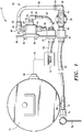
- Referring to
FIG. 1 , airtank purge system 10 includesautomatic valve assembly 12,air tank 14, andemergency brake system 16.Air tank 14 is fluidly connected toair input 18 ofautomatic valve assembly 12 viadrain line 20.Emergency brake system 16 is fluidly connected tocontrol input 22 ofautomatic valve assembly 12 viaemergency brake line 24. - As shown in
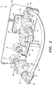
FIGS. 1-4 ,automatic valve assembly 12 includesvalve 26 andpressure regulator 28. Valve 26 includes aninput port 30, acontrol port 32, and anexhaust port 34.Input port 30 is fluidly connected toassembly air input 18 viapressure regulator 28,flexible tubing 36, andelbow connectors Control port 32 is fluidly connected toassembly control input 22, viaflexible tubing 42 andelbow connector 44.Exhaust port 34 is fluidly coupled toconnector 46 andexhaust line 48. Air and contaminants are purged fromair tank 14 throughexhaust port 34. In a preferred embodiment,exhaust line 48 exhausts the contaminants fromair tank 14 into the ambient air. In another embodiment,exhaust line 48 is fluidly coupled to a contaminant tank (not shown) to collect the contaminants to be discarded at a later time. - For one exemplary embodiment shown in
FIGS. 2-4 ,air input 18 is fluidly connected toinput port 30 in a manner to retain pressurized air betweeninput port 30 andair input 18.Air input 18 is coupled toregulator 28 via threadedconnector 50.Regulator 28 is coupled toelbow connector 38 via threadedconnector 52.Flexible tubing 36 is connected toelbow connector 38 viacompression coupler 54, andtubing 36 is coupled toelbow connector 40 viacompression coupler 56.Input port 30 is connected toelbow connector 40 via threadedconnector 58.Control input 22 is fluidly connected tocontrol port 32 in a manner to retain pressurized air betweencontrol port 32 andcontrol input 22.Control input 22 is coupled toflexible tubing 42 via threadedconnector 60.Flexible tubing 42 is coupled toelbow connector 44 viacompression coupler 62, andelbow connector 44 is coupled tocontrol port 32 via threadedconnector 64.Exhaust port 34 is coupled toexhaust line 48 viaelbow connector 46. Additionally, althoughFIGS. 2-4 show one embodiment of connectors and air lines connecting the different components ofautomatic valve assembly 12, the disclosure and claims herein extend to any type, number, or orientation of components for fluidly connectingair input 18 to inputport 30 and controlinput 22 to controlport 32. -
Flexible tubing exhaust line 48,emergency brake line 24, and drainline 20 are made of any suitable flexible tubing operable for pressurized fluid connections, and are preferably made of industrial standard brake tubing such as polyurethane flexible tubing.Elbow connectors -
Air tank 14 has anair supply port 66 and adrain 68.Air tank 14 supplies compressed air to the vehicle for various operations, including the regular operational brake system (not shown) andemergency brake system 16, throughair supply port 66.FIG. 1 showssupply line 70 connectingair tank 14 toemergency brake system 16 in phantom because there are typically other devices, lines, and regulators (not shown) connected betweenair supply port 66 andemergency brake system 16 such thatair tank 14 is not directly connected toemergency brake system 16.Drain 68 is an open port such that water and contaminants can fall through the port and settle alongdrain line 20 before the purging process begins. In a preferred embodiment, drain 68 is on a low point or the bottom ofair tank 14. In a preferred embodiment, drain 68 is coupled to a T-connector 72 operable to fluidly couple drain 68 tomanual drain valve 74 andautomatic valve assembly 12. Thus,manual drain valve 74 andautomatic valve assembly 12 operate independently and contaminants can be purged fromair tank 14 throughmanual drain valve 74 orautomatic valve assembly 12 separately or concurrently. In another embodiment,manual drain valve 74 is not included and drain 68 is only connected toautomatic valve assembly 12.Drain 68 is fluidly connected toautomatic valve assembly 12 viadrain line 20, andemergency brake system 16 is fluidly connected toautomatic valve assembly 12 viaemergency brake line 24.Air tank 14 is any suitable tank operable to store and provide air pressure (directly or indirectly) to the regular operational brake system (not shown),emergency brake system 16, and other components on the vehicle. An example of one suitable air tank is the Air Tank (Reservoir) model 19840 manufactured by Haldex and having a volume of approximately 1488 cubic inches. -
Manual drain valve 74 is preferably a conventional manual drain valve. A spring inmanual drain valve 74 keepsmanual drain valve 74 in a closed position such that contaminants and air cannot pass throughmanual drain valve 74.Manual line 76 allows a person to pull and manually compress the spring inmanual drain valve 74 and movemanual drain valve 74 to an open position such that contaminants and air pass throughmanual drain valve 74 into the atmosphere. Whenmanual line 76 is released, the spring inmanual drain valve 74 expands to movemanual drain valve 74 to the closed position. -
Pressure regulator 28 allows air and contaminants to flow through it until the pressure in regulator 28 (and thus in air tank 14) drops to or below a threshold value. Thus,pressure regulator 28 allows enough air to be expelled to assure all of the contaminants are expelled fromair tank 14 while retaining sufficient pressure within the air tank to operate pneumatic systems connected to the air tank, such asemergency brake system 16, without chargingair tank 14. When the air pressure drops to or below the threshold value,pressure regulator 28 stops air from flowing through it. The threshold value can be a set physical value depending on the type of regulator used, orpressure regulator 28 may be adjustable.Pressure regulator 28 preferably has a threshold at a high enough value to allowair tank 14 to retain sufficient pressure for the emergency brake line to be pressurized withoutair tank 14 needing to be re-pressurized by the air compressor. In a preferred embodiment, the threshold is preferably in a range from about 80 psi to about 120 psi, and more preferably in a range from about 90 psi to about 100 psi. Althoughpressure regulator 28 is shown inFIGS. 2-4 to be betweenair input 18 andinput port 30, regulator could be anywhere betweendrain 68 and where the contaminants are expelled (i.e., exhaust line 48). A suitable pressure regulator for purposes of the invention is Pressure Protection Valve model 90555396 manufactured by Haldex. -
Emergency brake system 16 is a standard pneumatic vehicle emergency brake system.Emergency brake system 16 includes an emergency brake at each wheel and emergency brake lines (not shown) that fluidly connect the emergency brakes toair tank 14. Typically, in pneumatic vehicle braking systems, the emergency brakes are engaged by a spring in each emergency brake. To disengage the emergency brakes for vehicle operation, the emergency brake lines are pressurized to compress the spring and disengage the emergency brakes from preventing rotation of the wheels. The emergency brake lines are pressurized fromair tank 14 and maintained at that pressure until the emergency brakes are set by a driver. When the driver sets the emergency brakes, the pressure from the emergency brake lines inemergency brake system 16 is released, and the springs in the emergency brakes expand to engage the emergency brakes.Emergency brake system 16 is fluidly connected to controlport 32 viaemergency brake line 24 such thatcontrol port 32 has substantially the same pressure as the emergency brakes inemergency brake system 16. - As shown in
FIGS. 7-8 ,valve 26 includes ahousing 100, avalve cap 102, abottom plug 104, atop diaphragm 106, abottom diaphragm 108, and apiston 110.Housing 100 defines openings forinput port 30,control port 32, andexhaust port 34.Piston 110 is positioned withinhousing 100 belowcontrol port 32 and between input andexhaust ports Piston 110 passes through openings intop diaphragm 106 andbottom diaphragm 108.Piston 110 includes a generallycylindrical rod 111 along with a top 112 anddiaphragm retainers rod 111 and having a diameter that is greater thanrod 111.Rod 111 has a groove opposite top 112 that receives a retainingring 120. - A central
cylindrical portion 106a oftop diaphragm 106 is secured betweentop 112 anddiaphragm retainer 114.Top diaphragm 106 has a flatcircular portion 106b extending outward fromcylindrical portion 106a.Valve cap 102 clamps aperipheral edge 122 oftop diaphragm 106 betweenvalve cap 102 andhousing 100 such thatdiaphragm 106 forms a seal betweenvalve cap 102 andhousing 100. An o-ring seal 124 is also positioned betweenvalve cap 102 andhousing 100.Valve cap 102 may be secured in place withinhousing 100 by any means known in the art. A centralcylindrical portion 108a ofbottom diaphragm 108 is secured betweendiaphragm retainer 116 and awasher 118 that abuts retainingring 120.Bottom diaphragm 108 has a flatcircular portion 108b extending outward fromcylindrical portion 108a.Bottom plug 104 clamps aperipheral edge 126 ofbottom diaphragm 108 betweenbottom plug 104 andhousing 100. An o-ring seal 128 is also positioned betweenbottom plug 104 andhousing 100.Bottom plug 104 and o-ring seal 128 prevent air from entering or exiting the lower portion ofhousing 100. Because the lower portion ofhousing 100 is plugged,bottom diaphragm 108,diaphragm retainer 116,washer 118, and retainingring 120 are not necessary and may be omitted fromvalve 26. Further, in lieu ofbottom plug 104 and o-ring seal 128, thehousing 100 may include an integral lower wall that prevents air from entering or exiting the lower portion ofhousing 100. Preferablydiaphragms piston 110 andcylindrical portions diaphragms housing 100 in a direction that is aligned with air enteringcontrol port 32. Awasher 130 is positioned withinhousing 100 betweentop diaphragm 106 and acentral wall 134 separating input andexhaust ports Washer 130 preventsdiaphragm 106 from collapsing when air is applied to thecontrol port 32 to move thepiston 110 to the closed position shown inFig. 8 . -
Valve 26 has an open position (as seen inFIG. 7 ) and a closed position (as seen inFIG. 8 ) depending on the pressure withincontrol port 32 and the pressure withininput port 30. The pressure withincontrol port 32 acts on the top 112 ofpiston 110 and an upper surface ofdiaphragm 106 to exert a downward force onpiston 110 anddiaphragm 106. The pressure withininput port 30 acts onwasher 130 and a lower surface ofdiaphragm 106 to exert an upward force onpiston 110 anddiaphragm 106.Valve 26 is in the open position shown inFig. 7 when the upward force onpiston 110 anddiaphragm 106 caused by the pressure withininput port 30 is greater than the downward force onpiston 110 anddiaphragm 106 caused by the pressure withincontrol port 32. In the open position, anair passageway 132 is formed betweencylindrical portion 106a ofdiaphragm 106 andcentral wall 134 of housing that allows air to flow betweeninput port 30 andexhaust port 34.Valve 26 is in the closed position shown inFig. 8 when the downward force onpiston 110 anddiaphragm 106 caused by the pressure withincontrol port 32 is greater than the upward force onpiston 110 anddiaphragm 106 caused by the pressure withininput port 30. In the closed position,cylindrical portion 106a ofdiaphragm 106 is forced into sealing engagement withcentral wall 134 to blockair passageway 132 and prevent air from flowing betweeninput port 30 andexhaust port 34. - Preferably, the surface area of the top 112 of
piston 110 and top ofdiaphragm 106 on which the pressure incontrol port 32 acts is greater than the surface area of the bottom ofwasher 130 and bottom ofdiaphragm 106 on which the pressure ininput port 30 acts such that thevalve 26 may be in its closed position when the pressure withincontrol port 32 is lower than the pressure withininput port 30. Alternatively, the surface area of the top 112 ofpiston 110 and top ofdiaphragm 106 may be equal to or less than the surface area of the bottom ofwasher 130 and bottom ofdiaphragm 106 such that the pressure withincontrol port 32 must be equal to or greater than the pressure withininput port 30 to maintainvalve 26 in its closed position. - The design of
valve 26 is such that there is a threshold value of the pressure withincontrol port 32. When the pressure withincontrol port 32 is above that threshold value, thevalve 26 is in its closed position, and when the pressure withincontrol port 32 is below that threshold value,valve 26 is in its open position. The threshold value is preferably between approximately 0 to 30 psi withincontrol port 32. - For example, when the air pressure in
control port 32 falls below the threshold value because the emergency brakes are set and brake line 24 (Fig. 1 ) is not pressurized, the upward force onpiston 110 caused by the air pressure ininput port 30 overcomes the downward force onpiston 110 caused by the pressure incontrol port 32 causingpiston 110 to move up to the open position (as shown inFIG. 7 ). In the open position,input port 30 andexhaust port 34 are in fluid connection such that air and contaminants fromair tank 14 can move frominput port 30, throughair passageway 132, aroundpiston 110, and be expelled throughexhaust port 34. When the air pressure incontrol port 32 is greater than the threshold value because the emergency brakes are not set andbrake line 24 is pressurized, the downward force onpiston 110 caused by the pressure incontrol port 32 overcomes the upward force onpiston 110 caused by the pressure ininput port 30 causingpiston 110 to move down to the closed position shown inFig. 8 . In the closed position,top diaphragm 106 is pushed againstcentral wall 134 thereby closingair passageway 132 such thatinput port 30 andexhaust port 34 are not in fluid connection. In the closed position, thecircular portion 106b ofdiaphragm 106 also preferably rests againstwasher 130. An example of one suitable type ofvalve 26 is Pilot Valve (Suspension Control Valve) model 90554615 manufactured by Haldex.Valve 26 is preferably a pilot valve because it is operable to place input andexhaust ports emergency brake line 24 andcontrol port 32. - Referring to
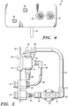
FIG. 5 ,automatic valve assembly 12 can includeinline filter 78 to prevent larger contaminants from entering the components ofautomatic valve assembly 12 that may negatively impact the functionality ofautomatic valve assembly 12.Inline filter 78 can be any suitable filter or screen. In one preferred embodiment,automatic valve assembly 12 includes a quick release connector to easily access and clean or replace inline filter 78 (not shown). Althoughfilter 78 is shown inFIG. 5 to be betweenair input 18 andregulator 28,filter 78 could be anywhere betweendrain 68 andvalve 26. - As shown in the several different views of
automatic valve assembly 12 inFIGS. 2-4 ,valve 26 is secured to abracket 80 viafasteners 82.Bracket 80 provides structure to the components ofautomatic valve assembly 12, and also allows easier installation forautomatic valve assembly 12.Air input 18 and controlinput 22 are provided to fluidly connectdrain 68 andemergency brake system 16 to inputport 30 andcontrol port 32 respectively throughbracket 80.Air input 18 and controlinput 22 preferably include a push-to-connect fitting, and more preferably a Bulkhead Push-To-Connect fitting model 66PMTBH-6-6 manufactured by Parking Fitting. In one exemplary embodiment,air input 18 and controlinput 22 are made from two threaded connector halves that are threaded together throughbracket 80. However,air input 18 and controlinput 22 may be any type of pneumatic fitting operable to provide fluid connection throughbracket 80. -
FIG. 4 demonstrates the simplicity provided byautomatic valve assembly 12 being secured tobracket 80. A person installingautomatic valve assembly 12 only needs to connectair input 18 to drain 68 via adrain line 20 and connectcontrol input 22 toemergency brake line 24. Thus,lines input 18 and controlinput 22 without the installer being concerned with or understanding how the components ofautomatic valve assembly 12 are connected and without any of the components ofautomatic valve assembly 12 getting in the way. - Referring to
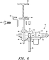
FIG. 6 , in one preferred embodiment,bracket 80 includesattachment mechanisms automatic valve assembly 12 to an I-beam 88 of a vehicle. In a preferred embodiment,attachment mechanism 84 is integral withbracket 80, andattachment mechanism 86 is secured toattachment mechanism 84 andbracket 80 via attachment means 90. In another embodiment,attachment mechanisms bracket 80 and are secured tobracket 80 via attachment means 90 through at least one aperture in bracket 80 (not shown).Attachment mechanisms automatic valve assembly 12 to other portions of a vehicle. In one alternative embodiment,automatic valve assembly 12 is attached to a larger bracket comprising several different mechanisms and assemblies as taught byU.S. Patent Application Publication No. 2010/0215429 which is incorporated herein by reference. -
Automatic valve assembly 12 can be installed on any existing vehicle utilizing compressed air, or can be installed on new vehicles during manufacture. If installed during vehicle manufacture,emergency brake line 24 could be a separate dedicated line connectingemergency brake system 16 andautomatic valve assembly 12. If installed on an existing vehicle,emergency brake system 16 typically does not have a spare line to run toautomatic valve assembly 12. An existing emergency brake line (not shown) may be cut and a connector (e.g., a T-connector) is installed that fluidly connects the existing emergency brake line toemergency brake line 24. - To install
automatic valve assembly 12 to an existing vehicle, an installer attaches theautomatic valve assembly 12 to the vehicle. This can be done by attachingautomatic valve assembly 12 to I-beam 88 usingattachment mechanisms FIG. 6 . Other attachment means may also be used. The installer then removesmanual drain valve 74 fromdrain 68 and inserts aconnector 72 intodrain 68. Ifmanual drain valve 74 is to remain onair tank 14,connector 72 comprises at least two connector ends, andmanual drain valve 74 is attached to one end ofconnector 72 and a first end ofdrain line 20 is connected to another end ofconnector 72. Ifmanual drain valve 74 is not to remain onair tank 14,connector 72 only comprises one connector end, and a first end ofdrain line 20 can be connected toconnector 72. Alternatively, a first end ofdrain line 20 can be connected directly to drain 68, or a plug (not shown) could be connected to an end ofconnector 72. The other end ofdrain line 20 is then connected to airinput 18. - The installer then cuts an emergency brake line (not shown) in
emergency brake system 16, and installs a connector (not shown) to fluidly connect the severed emergency brake line andemergency brake line 24. Typically, the connector is a T-type connector, though other connectors may be used.Emergency brake line 24 is then connected to controlinput 22. Alternatively, ifemergency brake system 16 provides an extra emergency brake line, the extra emergency brake line can be used asemergency brake line 24 and can simply be connected to controlinput 22. - A simple non-limiting example is now given to illustrate the operation of the present invention. For this example, we will assume air
tank purge system 10 resides on an unpowered semitrailer that does not have access to the air compressor when parked, and theautomatic valve assembly 12 is mounted to one of the trailer I-beams as shown inFIG. 6 . Additionally, we will assume thatair tank 14 maintains a pressure of 120 psi during operation andair pressure regulator 28 stops air flow at 90 psi. When the driver releases the parking/emergency brake, air fromair tank 14 pressurizes the emergency brake lines inemergency brake system 16 to 120 psi. As a result of the emergency brake lines being pressurized to 120 psi, the springs in the emergency brakes are compressed such that the emergency brakes are disengaged.Emergency brake line 24 andcontrol port 32 are also pressurized at 120 psi. At this pressure,valve 26 is in its closed position because the downward force onpiston 110 caused by the pressure withincontrol port 32 is greater than the upward force onpiston 110 caused by the pressure withininput port 30. This prevents air and contaminants from being expelled throughautomatic valve assembly 12. The emergency brakes and automatic valve assembly are not used while the semitrailer is moving. - When the trailer is parked, the driver typically sets the parking/emergency brake. This releases the pressure from the emergency brake lines in
emergency brake system 16, causing the springs in the emergency brakes to expand, thereby engaging the emergency brakes. As a result,emergency brake line 24 andcontrol port 32 are not pressurized, which causesvalve 26 to move to its open position as the upward force onpiston 110 caused by the pressure withininput port 30 is greater than the downward force onpiston 110 caused by the pressure withincontrol port 32. Whenvalve 26 is in its open position, air and contaminants travel fromair pressure tank 14, throughautomatic valve assembly 12, and are expelled out ofexhaust port 34.Valve 26 remains in the open position until the emergency brakes are disengaged (i.e., the emergency brake line is pressurized). Withpressure regulator 28, air and contaminants continue to be expelled until the pressure intank 14 drops below the threshold indicated bypressure regulator 28, here 90 psi. Once the pressure intank 14reaches 90 psi,air pressure regulator 28 does not allow any more air to flow. The remaining air pressure (90 psi) is sufficient to release the parking/emergency brakes when the driver returns to the vehicle without waiting forair tank 14 to be charged. Withoutpressure regulator 28, air and contaminants would continue to flow until there was no air pressure remaining in air tank 14 (∼0 psi). In this embodiment,air tank 14 would have to be charged before the parking/emergency brake can be disengaged for the trailer to be used. - If the air
tank purge system 10 is located on a trailer or dolly that is towed by another vehicle, such as a semi-tractor, when the trailer or dolly is disconnected from the towing vehicle, theemergency brake line 24 is disconnected fromcontrol input 22. Disconnection of theemergency brake line 24 opensvalve 26 to purge theair tank 14 in the same manner described above with respect to setting of the parking/emergency brake. - Thus, as described above, the present invention is directed to a system, valve assembly and method for automatically purging an air pressure tank each time the parking brake on the vehicle is set. The system, valve assembly and method do not require any electricity or connection to the compressor to turn off/on. The system is turned on when the parking brake is set, and turned off when the parking brake is released. The pressure regulator keeps enough pressure in the tank to allow pneumatic systems, such as the emergency brake system, to operate without charging the tank. Thus, the tank is automatically purged on a regular basis, thereby improving the performance and lifespan of the components.
- Exemplary embodiments of the invention comprise a valve assembly and a system in accordance with the independent claims 1 and 7 and with the claims dependent there on.
- From the foregoing it will be seen that this invention is one well adapted to attain all ends and objectives herein-above set forth, together with the other advantages which are obvious and which are inherent to the invention.
- Since many possible embodiments may be made of the invention without departing from the scope thereof, it is to be understood that all matters herein set forth or shown in the accompanying drawings are to be interpreted as illustrative, and not in a limiting sense.
- While specific embodiments have been shown and discussed, various modifications may of course be made, and the invention is not limited to the specific forms or arrangement of parts and steps described herein, except insofar as such limitations are included in the following claims. This is contemplated by and is within the scope of the claims.
Claims (16)
- A valve assembly (12) for purging contaminants from a pressurized air tank (14) on a vehicle, the valve assembly (12) comprising:a valve (26) comprising:an input port (30);an exhaust port (34); anda control port (32) operable to be fluidly connected with an emergency brake line, wherein said control port (32) is configured such that when the emergency brake line (24) is pressurized, the valve is in a closed position such that the input port (30) and exhaust port (34) are not in fluid connection;wherein the valve assembly (12) is characterized in that:said input port is operable to be fluidly connected with a drain (68) on a pressurized air tank (14);
wherein said control port is configured such that when the emergency brake line (24) is not pressurized or the emergency brake line is disconnected from the valve (26), the valve is in an open position such that the input port (30) and the exhaust port (34) are in fluid connection operable for air and contaminants from the pressurized air tank (14) to be expelled from the pressurized air tank (14) through the exhaust port (34); and
an air pressure regulator (28) operable to be fluidly connected with at least one of the drain (68) and the exhaust port (34),wherein the air pressure regulator (28) is operable to stop air and contaminants from the pressurized air tank (14) from flowing through the pressure regulator (28) and from flowing between the input port (30) of the valve (26) and the exhaust port (34) of the valve (26) when a pressure in the pressurized air tank (14) falls below a threshold value, andwherein air and contaminants from the pressurized air tank (14) flow through the pressure regulator (28) and between the input port of the valve (26) and the exhaust port (34) of the valve when the pressure in the pressurized air tank is above the threshold value and the valve (26) is in the open position. - The valve assembly of claim 1, wherein the air pressure regulator (28) is operable to be connected between the drain (68) and the input port (30).
- The valve assembly of claim 1, wherein the air pressure regulator (28) is connected to the exhaust port (34).
- The valve assembly of claim 1, wherein the valve is coupled to a bracket (80).
- The valve assembly of claim 4, wherein the bracket (80) is operable to be connected to the vehicle or to a trailer.
- The valve assembly of claim 1, wherein the valve (26) comprises a housing (100) defining the input (30), exhaust (34), and control (32) ports and a diaphragm (106) moveable between the closed and open positions, wherein the diaphragm (106) seals against the housing (100) when the valve (26) is in its closed position preventing air from flowing between the input (30) and exhaust (34) ports, and wherein there is a passageway between the diaphragm (106) and housing (100) through which air can flow from the input port (30) to the exhaust port (34) when the valve (26) is in its open position.
- A system for purging contaminants from a pressurized air tank on a vehicle, the system comprising:
a valve (26) comprising:an input port (30);an exhaust port (34); anda control port (32) in fluid connection with an emergency brake line (24) on the vehicle, wherein when the emergency brake line (24) is pressurized, the valve (26) is in a closed position such that the input port (30) and exhaust port (34) are not in fluid connection;wherein the system is characterized in that:said input port is in fluid connection with a drain (68) on a pressurized air tank (14);
wherein when the emergency brake line (24) is not pressurized or the emergency brake line is disconnected from the valve (26), the valve (26) is in an open position such that the input port (30) and the exhaust port (34) are in fluid connection operable for air and contaminants from the pressurized air tank to be expelled from the pressurized air tank (14) through the exhaust port (34); andan air pressure regulator (28) is in fluid connection with at least one of the drain (68) and the exhaust port (34),wherein the air pressure regulator (28) is operable to stop air and contaminants from the pressurized air tank (14) from flowing through the pressure regulator (28) and from flowing between the input port (30) of the valve (26) and the exhaust port (34) of the valve (26) when a pressure in the pressurized air tank (14) falls below a threshold value, andwherein air and contaminants from the pressurized air tank (14) flow through the pressure regulator (28) and between the input port (30) of the valve (26) and the exhaust port of the valve (26) when the pressure in the pressurized air tank is above the threshold value and the valve (26) is in the open position. - The system of claim 7, wherein said drain (68) is positioned at a low point of the pressurized air tank.
- The system of claim 7, wherein the air pressure regulator is connected between the drain (68) and the input port (30).
- The system of claim 7, wherein the air pressure regulator (28) is connected to the exhaust port (34).
- The system of claim 7, further comprising a manual drain valve (74) coupled to the drain (68).
- The system of claim 11, wherein the manual drain valve (74) operates independently of the valve (26).
- The system of claim 7, wherein the exhaust port (34) is coupled with a holding tank that retains the expelled contaminants for later disposal.
- The system of claim 7, wherein the threshold value is in a range of from about 80 psi to about 120 psi or in a range of from about 90 psi to about 100 psi.
- The system of claim 7, wherein the threshold value is modifiable.
- The system of claim 7, wherein the valve (26) comprises a housing (100) defining the input (30), exhaust (34), and control (32) ports and a diaphragm (106) moveable between the closed and open positions, wherein the diaphragm (106) seals against the housing (100) when the valve (26) is in its closed position preventing air from flowing between the input (30) and exhaust (34) ports, and wherein there is a passageway between the diaphragm (106) and housing through which air can flow from the input port (30) to the exhaust port (34) when the valve (26) is in its open position.
Applications Claiming Priority (2)
| Application Number | Priority Date | Filing Date | Title |
|---|---|---|---|
| US201361772822P | 2013-03-05 | 2013-03-05 | |
| US13/830,178 US9834192B2 (en) | 2013-03-05 | 2013-03-14 | Automatic air tank purge system |
Publications (2)
| Publication Number | Publication Date |
|---|---|
| EP2774821A1 EP2774821A1 (en) | 2014-09-10 |
| EP2774821B1 true EP2774821B1 (en) | 2018-10-10 |
Family
ID=50193341
Family Applications (1)
| Application Number | Title | Priority Date | Filing Date |
|---|---|---|---|
| EP14157668.6A Not-in-force EP2774821B1 (en) | 2013-03-05 | 2014-03-04 | Automatic air tank purge system |
Country Status (7)
| Country | Link |
|---|---|
| US (1) | US9834192B2 (en) |
| EP (1) | EP2774821B1 (en) |
| CN (1) | CN104029667B (en) |
| BR (1) | BR102014005102A2 (en) |
| CA (1) | CA2812341C (en) |
| IN (1) | IN2014MU00743A (en) |
| MX (1) | MX355160B (en) |
Families Citing this family (9)
| Publication number | Priority date | Publication date | Assignee | Title |
|---|---|---|---|---|
| US10502329B2 (en) | 2015-11-23 | 2019-12-10 | Haldex Brake Products Corporation | Reservoir purge valve |
| US10315638B2 (en) * | 2016-07-07 | 2019-06-11 | Robert Lambertus Dekam | Air braking system |
| CN107336702B (en) * | 2017-08-03 | 2023-07-14 | 眉山中车制动科技股份有限公司 | Connection structure and system of integrated brake device for railway vehicle |
| DE102018111894A1 (en) * | 2018-05-17 | 2019-11-21 | Wabco Gmbh | Valve assembly as parking release valve for a trailer |
| EP3733462B1 (en) * | 2019-04-30 | 2024-01-24 | Volvo Car Corporation | A cleaning system connected to an air suspension system |
| CN112240673B (en) * | 2019-07-17 | 2022-05-20 | 青岛海尔电冰箱有限公司 | Air duct system and refrigeration equipment with same |
| IT202100008420A1 (en) | 2021-04-06 | 2022-10-06 | Tosi F Lli S R L | AUTOMATIC DRAINAGE VALVE FOR PNEUMATIC SYSTEMS. |
| CN113859205B (en) * | 2021-09-30 | 2023-09-22 | 三一专用汽车有限责任公司 | Drainage control method and device of braking system, braking system and vehicle |
| CN115946664B (en) * | 2022-12-23 | 2023-07-14 | 芜湖盛力科技股份有限公司 | Pneumatic control hydraulic stop valve and brake circulation cooling system |
Family Cites Families (51)
| Publication number | Priority date | Publication date | Assignee | Title |
|---|---|---|---|---|
| US3262464A (en) | 1966-07-26 | Drain valve | ||
| US3298387A (en) * | 1967-01-17 | Automatic drain valves for air reservoirs | ||
| US891808A (en) | 1907-12-14 | 1908-06-30 | Frederick W Adams | Automatic drain-cock for air-brakes. |
| US948344A (en) | 1909-10-23 | 1910-02-08 | John G Radick | Automatic drain-cock. |
| US1001040A (en) | 1910-01-31 | 1911-08-22 | Henry K Johnsonbaugh | Air-brake emergency-valve. |
| US2077515A (en) * | 1934-11-23 | 1937-04-20 | New York Air Brake Co | Air brake |
| US2328649A (en) | 1942-06-08 | 1943-09-07 | New York Air Brake Co | Air brake |
| US2383244A (en) | 1943-05-27 | 1945-08-21 | Westinghouse Air Brake Co | Automatic drain valve |
| US2418440A (en) | 1945-01-05 | 1947-04-01 | Martin H White | Pressure operated drain valve |
| US2509597A (en) * | 1946-08-19 | 1950-05-30 | Lloyd L Hamilton | Automatic drain valve for compressed air reservoirs |
| US2485232A (en) | 1947-03-06 | 1949-10-18 | George T Brown | Drainage valve system |
| US2687841A (en) | 1947-12-29 | 1954-08-31 | Nellie Churchman | Valve used as a control |
| US2509880A (en) * | 1948-05-04 | 1950-05-30 | Robert L Pelton | Air pressure mechanism |
| US2810393A (en) | 1955-07-28 | 1957-10-22 | Wagner Electric Corp | Automatic drain valve |
| US3101091A (en) * | 1958-03-31 | 1963-08-20 | Midland Ross Corp | Moisture ejection valve |
| FR1363011A (en) * | 1963-07-08 | 1964-06-05 | Davies & Metcalfe | Automatic drain valve |
| US3533433A (en) * | 1968-07-05 | 1970-10-13 | Berg Mfg & Sales Co | Water ejection valve for vehicle brake system |
| US3575199A (en) | 1968-11-04 | 1971-04-20 | Reef Baker Corp | Automatic condensate valve |
| US3580267A (en) | 1969-09-26 | 1971-05-25 | Ralph J Baker | Condensate valve |
| US3659625A (en) * | 1970-02-16 | 1972-05-02 | Westinghouse Air Brake Co | Drain valve device |
| US3682194A (en) * | 1970-04-24 | 1972-08-08 | Reef Baker Corp | Condensate valve |
| US3977426A (en) | 1975-02-03 | 1976-08-31 | Reef-Baker Corporation | Condensate valve assembly |
| US4030517A (en) * | 1975-02-03 | 1977-06-21 | Reef-Baker Corporation | Condensate valve assembly |
| US4146275A (en) | 1977-10-11 | 1979-03-27 | Elliott Robert H | Residual pressure relief valve for brakes |
| US4877218A (en) * | 1986-05-15 | 1989-10-31 | Design Improvement Corporation | Drain valve device |
| US4883995A (en) | 1988-12-30 | 1989-11-28 | General Electric Company | Automatic oil draining system for generators |
| US5205315B1 (en) * | 1989-03-30 | 1998-12-15 | Matteo Augustine J Jr | Automatic wet tank drain valve |
| US4928724A (en) | 1989-03-30 | 1990-05-29 | Margerum Wayne R | Automatic wet tank drain valve |
| US5435422A (en) | 1989-04-03 | 1995-07-25 | Chille, Sr.; Frank A. | Automatic wet tank drain valve |
| US4987919A (en) | 1989-08-08 | 1991-01-29 | Lucien Orichefsky | Pneumatically activated drain valve for compressed air |
| US5144974A (en) | 1991-04-12 | 1992-09-08 | Jeffrey Gaudin | Purge valve assembly |
| US5154204A (en) | 1991-07-19 | 1992-10-13 | Westinghouse Air Brake Company | Automatic drain valve for a compressed air system |
| US5286283A (en) * | 1993-05-17 | 1994-02-15 | Alliedsignal Inc. | Air dryer for compressed air system having a serviceable oil filter |
| US5592754A (en) | 1996-06-07 | 1997-01-14 | Alliedsignal Truck Brake Systems Co. | Electronic control of compressor unloader and air dryer purge |
| GB9613707D0 (en) * | 1996-06-29 | 1996-08-28 | Wabco Automotive Uk | A drain valve |
| US5947239A (en) * | 1996-08-26 | 1999-09-07 | Haldex Financial Services Corporation | Contaminant-ejecting relay valve for a pneumatic brake system |
| US5709246A (en) * | 1996-11-04 | 1998-01-20 | Midland Brake, Inc. | Booster valve with contaminant ejection for use in a pneumatic brake system |
| US5941271A (en) * | 1997-02-04 | 1999-08-24 | Chovan; Dale | Water release valve |
| US5738138A (en) | 1997-03-10 | 1998-04-14 | The Horton Company | Reduced water hammer control valve |
| US5762094A (en) * | 1997-04-11 | 1998-06-09 | Alliedsignal Truck Brake Systems Co. | Automatic valve drain |
| US6227520B1 (en) | 1999-01-19 | 2001-05-08 | New York Air Brake Corporation | Diaphragm piston valve |
| US6238013B1 (en) | 1999-06-30 | 2001-05-29 | Haldex Brake Corporation | Solenoid-activated contaminant ejecting relay valve |
| US6170511B1 (en) | 1999-08-24 | 2001-01-09 | Westinghouse Air Brake Company | Normally open purge valve |
| US6164312A (en) | 1999-08-24 | 2000-12-26 | Westinghouse Air Brake Company | Purge valve |
| US6267135B1 (en) | 2000-05-03 | 2001-07-31 | Honeywell Commerical Vehicle Systems Co. | ABS modulator with damping foam on exhaust diaphragm |
| US6425935B1 (en) * | 2000-05-03 | 2002-07-30 | Bendix Commercial Vehicle Systems Llc. | Trailer air dryer with purge during park feature |
| US6588856B2 (en) | 2001-07-30 | 2003-07-08 | Bendix Commercial Vehicle Systems Llc | Modulator relay valve assembly and method |
| US7334847B2 (en) * | 2003-10-09 | 2008-02-26 | Bendix Commercial Vehicle Systems Llc | Single line remote purge air dryer |
| US7338550B2 (en) | 2005-08-02 | 2008-03-04 | Arvinmeritor Technology, Llc | Axle assembly with purge reservoir for air dryer |
| US20070251781A1 (en) | 2006-04-28 | 2007-11-01 | International Truck Intellectual Property Company, Llc | Remote drain valve device for an air brake vehicle |
| US8511929B2 (en) * | 2009-02-25 | 2013-08-20 | Haldex Brake Corporation | Trailer/dolly ABS system module |
-
2013
- 2013-03-14 US US13/830,178 patent/US9834192B2/en active Active
- 2013-04-12 CA CA2812341A patent/CA2812341C/en active Active
- 2013-04-30 MX MX2013004890A patent/MX355160B/en active IP Right Grant
-
2014
- 2014-03-04 EP EP14157668.6A patent/EP2774821B1/en not_active Not-in-force
- 2014-03-04 IN IN743MU2014 patent/IN2014MU00743A/en unknown
- 2014-03-05 CN CN201410246660.8A patent/CN104029667B/en not_active Expired - Fee Related
- 2014-03-05 BR BRBR102014005102-3A patent/BR102014005102A2/en active Search and Examination
Non-Patent Citations (1)
| Title |
|---|
| None * |
Also Published As
| Publication number | Publication date |
|---|---|
| EP2774821A1 (en) | 2014-09-10 |
| MX355160B (en) | 2018-04-06 |
| MX2013004890A (en) | 2014-09-16 |
| BR102014005102A2 (en) | 2014-12-09 |
| CN104029667A (en) | 2014-09-10 |
| CA2812341C (en) | 2019-06-11 |
| US9834192B2 (en) | 2017-12-05 |
| US20140251437A1 (en) | 2014-09-11 |
| IN2014MU00743A (en) | 2015-09-25 |
| CN104029667B (en) | 2019-04-30 |
| CA2812341A1 (en) | 2014-09-05 |
Similar Documents
| Publication | Publication Date | Title |
|---|---|---|
| EP2774821B1 (en) | Automatic air tank purge system | |
| US11105431B2 (en) | Reservoir purge valve | |
| CN103260913B (en) | There is the valve rod of auxiliary port | |
| EP2242673B1 (en) | Internal ventilating diaphragm piston brake actuator | |
| US9290166B2 (en) | Vehicle braking system | |
| US20090256416A1 (en) | Brake system for a vehicle | |
| WO2009046780A3 (en) | Electropneumatic parking brake modulator for a trailer in a vehicle/trailer combination | |
| US20070158146A1 (en) | Brake Actuator | |
| US9434366B1 (en) | Parking apparatus for a heavy vehicle during a loss of electrical power | |
| HUE033680T2 (en) | Trailer park brake valve arrangement | |
| US6378414B1 (en) | Removable filter cap for spring brake actuator | |
| WO2019243282A3 (en) | Parking brake device for a motor vehicle | |
| US2781870A (en) | Emergency air brake actuator | |
| KR102059629B1 (en) | An internal ventilating diaphragm - diaphragm spring brake actuator | |
| US6389954B1 (en) | Removable filter plug for spring brake actuator | |
| CN103359101A (en) | Intermediate emergency relay valve of motor vehicle trailer | |
| EP1747133B1 (en) | Improvements in air dryers | |
| CN205706651U (en) | Hollow intussusception cylinder activation device | |
| RU2771951C2 (en) | Tubular bracket for vehicle brake camshaft valve, vehicle brake camshaft valve and gasket for vehicle brake camshaft valve | |
| US20070251781A1 (en) | Remote drain valve device for an air brake vehicle | |
| CN219139961U (en) | Fuel tank oil pressure opening valve and pressure fuel system | |
| CN220884365U (en) | Vehicle with a vehicle body having a vehicle body support | |
| US11731605B2 (en) | Bracket for a distributor valve | |
| JP7150477B2 (en) | Impurity removal system and compressed air distribution device for towed vehicles | |
| EP3408150B1 (en) | An internal ventilated diaphragm-piston spring brake actuator |
Legal Events
| Date | Code | Title | Description |
|---|---|---|---|
| PUAI | Public reference made under article 153(3) epc to a published international application that has entered the european phase |
Free format text: ORIGINAL CODE: 0009012 |
|
| 17P | Request for examination filed |
Effective date: 20140304 |
|
| AK | Designated contracting states |
Kind code of ref document: A1 Designated state(s): AL AT BE BG CH CY CZ DE DK EE ES FI FR GB GR HR HU IE IS IT LI LT LU LV MC MK MT NL NO PL PT RO RS SE SI SK SM TR |
|
| AX | Request for extension of the european patent |
Extension state: BA ME |
|
| R17P | Request for examination filed (corrected) |
Effective date: 20150306 |
|
| RBV | Designated contracting states (corrected) |
Designated state(s): AL AT BE BG CH CY CZ DE DK EE ES FI FR GB GR HR HU IE IS IT LI LT LU LV MC MK MT NL NO PL PT RO RS SE SI SK SM TR |
|
| GRAP | Despatch of communication of intention to grant a patent |
Free format text: ORIGINAL CODE: EPIDOSNIGR1 |
|
| STAA | Information on the status of an ep patent application or granted ep patent |
Free format text: STATUS: GRANT OF PATENT IS INTENDED |
|
| INTG | Intention to grant announced |
Effective date: 20180522 |
|
| RIN1 | Information on inventor provided before grant (corrected) |
Inventor name: ENGELBERT, DAVID G. Inventor name: RAYE, VICTOR J. |
|
| GRAS | Grant fee paid |
Free format text: ORIGINAL CODE: EPIDOSNIGR3 |
|
| GRAA | (expected) grant |
Free format text: ORIGINAL CODE: 0009210 |
|
| STAA | Information on the status of an ep patent application or granted ep patent |
Free format text: STATUS: THE PATENT HAS BEEN GRANTED |
|
| AK | Designated contracting states |
Kind code of ref document: B1 Designated state(s): AL AT BE BG CH CY CZ DE DK EE ES FI FR GB GR HR HU IE IS IT LI LT LU LV MC MK MT NL NO PL PT RO RS SE SI SK SM TR |
|
| REG | Reference to a national code |
Ref country code: GB Ref legal event code: FG4D |
|
| REG | Reference to a national code |
Ref country code: CH Ref legal event code: EP Ref country code: AT Ref legal event code: REF Ref document number: 1050863 Country of ref document: AT Kind code of ref document: T Effective date: 20181015 |
|
| REG | Reference to a national code |
Ref country code: IE Ref legal event code: FG4D Ref country code: DE Ref legal event code: R096 Ref document number: 602014033639 Country of ref document: DE |
|
| REG | Reference to a national code |
Ref country code: NL Ref legal event code: MP Effective date: 20181010 |
|
| REG | Reference to a national code |
Ref country code: LT Ref legal event code: MG4D |
|
| REG | Reference to a national code |
Ref country code: AT Ref legal event code: MK05 Ref document number: 1050863 Country of ref document: AT Kind code of ref document: T Effective date: 20181010 |
|
| PG25 | Lapsed in a contracting state [announced via postgrant information from national office to epo] |
Ref country code: NL Free format text: LAPSE BECAUSE OF FAILURE TO SUBMIT A TRANSLATION OF THE DESCRIPTION OR TO PAY THE FEE WITHIN THE PRESCRIBED TIME-LIMIT Effective date: 20181010 |
|
| PG25 | Lapsed in a contracting state [announced via postgrant information from national office to epo] |
Ref country code: LV Free format text: LAPSE BECAUSE OF FAILURE TO SUBMIT A TRANSLATION OF THE DESCRIPTION OR TO PAY THE FEE WITHIN THE PRESCRIBED TIME-LIMIT Effective date: 20181010 Ref country code: ES Free format text: LAPSE BECAUSE OF FAILURE TO SUBMIT A TRANSLATION OF THE DESCRIPTION OR TO PAY THE FEE WITHIN THE PRESCRIBED TIME-LIMIT Effective date: 20181010 Ref country code: NO Free format text: LAPSE BECAUSE OF FAILURE TO SUBMIT A TRANSLATION OF THE DESCRIPTION OR TO PAY THE FEE WITHIN THE PRESCRIBED TIME-LIMIT Effective date: 20190110 Ref country code: AT Free format text: LAPSE BECAUSE OF FAILURE TO SUBMIT A TRANSLATION OF THE DESCRIPTION OR TO PAY THE FEE WITHIN THE PRESCRIBED TIME-LIMIT Effective date: 20181010 Ref country code: FI Free format text: LAPSE BECAUSE OF FAILURE TO SUBMIT A TRANSLATION OF THE DESCRIPTION OR TO PAY THE FEE WITHIN THE PRESCRIBED TIME-LIMIT Effective date: 20181010 Ref country code: IS Free format text: LAPSE BECAUSE OF FAILURE TO SUBMIT A TRANSLATION OF THE DESCRIPTION OR TO PAY THE FEE WITHIN THE PRESCRIBED TIME-LIMIT Effective date: 20190210 Ref country code: LT Free format text: LAPSE BECAUSE OF FAILURE TO SUBMIT A TRANSLATION OF THE DESCRIPTION OR TO PAY THE FEE WITHIN THE PRESCRIBED TIME-LIMIT Effective date: 20181010 Ref country code: HR Free format text: LAPSE BECAUSE OF FAILURE TO SUBMIT A TRANSLATION OF THE DESCRIPTION OR TO PAY THE FEE WITHIN THE PRESCRIBED TIME-LIMIT Effective date: 20181010 Ref country code: BG Free format text: LAPSE BECAUSE OF FAILURE TO SUBMIT A TRANSLATION OF THE DESCRIPTION OR TO PAY THE FEE WITHIN THE PRESCRIBED TIME-LIMIT Effective date: 20190110 Ref country code: PL Free format text: LAPSE BECAUSE OF FAILURE TO SUBMIT A TRANSLATION OF THE DESCRIPTION OR TO PAY THE FEE WITHIN THE PRESCRIBED TIME-LIMIT Effective date: 20181010 |
|
| PG25 | Lapsed in a contracting state [announced via postgrant information from national office to epo] |
Ref country code: GR Free format text: LAPSE BECAUSE OF FAILURE TO SUBMIT A TRANSLATION OF THE DESCRIPTION OR TO PAY THE FEE WITHIN THE PRESCRIBED TIME-LIMIT Effective date: 20190111 Ref country code: RS Free format text: LAPSE BECAUSE OF FAILURE TO SUBMIT A TRANSLATION OF THE DESCRIPTION OR TO PAY THE FEE WITHIN THE PRESCRIBED TIME-LIMIT Effective date: 20181010 Ref country code: SE Free format text: LAPSE BECAUSE OF FAILURE TO SUBMIT A TRANSLATION OF THE DESCRIPTION OR TO PAY THE FEE WITHIN THE PRESCRIBED TIME-LIMIT Effective date: 20181010 Ref country code: PT Free format text: LAPSE BECAUSE OF FAILURE TO SUBMIT A TRANSLATION OF THE DESCRIPTION OR TO PAY THE FEE WITHIN THE PRESCRIBED TIME-LIMIT Effective date: 20190210 Ref country code: AL Free format text: LAPSE BECAUSE OF FAILURE TO SUBMIT A TRANSLATION OF THE DESCRIPTION OR TO PAY THE FEE WITHIN THE PRESCRIBED TIME-LIMIT Effective date: 20181010 |
|
| REG | Reference to a national code |
Ref country code: DE Ref legal event code: R097 Ref document number: 602014033639 Country of ref document: DE |
|
| PG25 | Lapsed in a contracting state [announced via postgrant information from national office to epo] |
Ref country code: DK Free format text: LAPSE BECAUSE OF FAILURE TO SUBMIT A TRANSLATION OF THE DESCRIPTION OR TO PAY THE FEE WITHIN THE PRESCRIBED TIME-LIMIT Effective date: 20181010 Ref country code: IT Free format text: LAPSE BECAUSE OF FAILURE TO SUBMIT A TRANSLATION OF THE DESCRIPTION OR TO PAY THE FEE WITHIN THE PRESCRIBED TIME-LIMIT Effective date: 20181010 Ref country code: CZ Free format text: LAPSE BECAUSE OF FAILURE TO SUBMIT A TRANSLATION OF THE DESCRIPTION OR TO PAY THE FEE WITHIN THE PRESCRIBED TIME-LIMIT Effective date: 20181010 |
|
| PLBE | No opposition filed within time limit |
Free format text: ORIGINAL CODE: 0009261 |
|
| STAA | Information on the status of an ep patent application or granted ep patent |
Free format text: STATUS: NO OPPOSITION FILED WITHIN TIME LIMIT |
|
| PG25 | Lapsed in a contracting state [announced via postgrant information from national office to epo] |
Ref country code: SK Free format text: LAPSE BECAUSE OF FAILURE TO SUBMIT A TRANSLATION OF THE DESCRIPTION OR TO PAY THE FEE WITHIN THE PRESCRIBED TIME-LIMIT Effective date: 20181010 Ref country code: RO Free format text: LAPSE BECAUSE OF FAILURE TO SUBMIT A TRANSLATION OF THE DESCRIPTION OR TO PAY THE FEE WITHIN THE PRESCRIBED TIME-LIMIT Effective date: 20181010 Ref country code: EE Free format text: LAPSE BECAUSE OF FAILURE TO SUBMIT A TRANSLATION OF THE DESCRIPTION OR TO PAY THE FEE WITHIN THE PRESCRIBED TIME-LIMIT Effective date: 20181010 Ref country code: SM Free format text: LAPSE BECAUSE OF FAILURE TO SUBMIT A TRANSLATION OF THE DESCRIPTION OR TO PAY THE FEE WITHIN THE PRESCRIBED TIME-LIMIT Effective date: 20181010 |
|
| 26N | No opposition filed |
Effective date: 20190711 |
|
| REG | Reference to a national code |
Ref country code: DE Ref legal event code: R119 Ref document number: 602014033639 Country of ref document: DE |
|
| PG25 | Lapsed in a contracting state [announced via postgrant information from national office to epo] |
Ref country code: SI Free format text: LAPSE BECAUSE OF FAILURE TO SUBMIT A TRANSLATION OF THE DESCRIPTION OR TO PAY THE FEE WITHIN THE PRESCRIBED TIME-LIMIT Effective date: 20181010 Ref country code: MC Free format text: LAPSE BECAUSE OF FAILURE TO SUBMIT A TRANSLATION OF THE DESCRIPTION OR TO PAY THE FEE WITHIN THE PRESCRIBED TIME-LIMIT Effective date: 20181010 |
|
| REG | Reference to a national code |
Ref country code: CH Ref legal event code: PL |
|
| GBPC | Gb: european patent ceased through non-payment of renewal fee |
Effective date: 20190304 |
|
| PG25 | Lapsed in a contracting state [announced via postgrant information from national office to epo] |
Ref country code: LU Free format text: LAPSE BECAUSE OF NON-PAYMENT OF DUE FEES Effective date: 20190304 |
|
| REG | Reference to a national code |
Ref country code: BE Ref legal event code: MM Effective date: 20190331 |
|
| PG25 | Lapsed in a contracting state [announced via postgrant information from national office to epo] |
Ref country code: LI Free format text: LAPSE BECAUSE OF NON-PAYMENT OF DUE FEES Effective date: 20190331 Ref country code: GB Free format text: LAPSE BECAUSE OF NON-PAYMENT OF DUE FEES Effective date: 20190304 Ref country code: IE Free format text: LAPSE BECAUSE OF NON-PAYMENT OF DUE FEES Effective date: 20190304 Ref country code: CH Free format text: LAPSE BECAUSE OF NON-PAYMENT OF DUE FEES Effective date: 20190331 Ref country code: DE Free format text: LAPSE BECAUSE OF NON-PAYMENT OF DUE FEES Effective date: 20191001 |
|
| PG25 | Lapsed in a contracting state [announced via postgrant information from national office to epo] |
Ref country code: BE Free format text: LAPSE BECAUSE OF NON-PAYMENT OF DUE FEES Effective date: 20190331 Ref country code: FR Free format text: LAPSE BECAUSE OF NON-PAYMENT OF DUE FEES Effective date: 20190331 |
|
| PG25 | Lapsed in a contracting state [announced via postgrant information from national office to epo] |
Ref country code: TR Free format text: LAPSE BECAUSE OF FAILURE TO SUBMIT A TRANSLATION OF THE DESCRIPTION OR TO PAY THE FEE WITHIN THE PRESCRIBED TIME-LIMIT Effective date: 20181010 |
|
| PG25 | Lapsed in a contracting state [announced via postgrant information from national office to epo] |
Ref country code: MT Free format text: LAPSE BECAUSE OF NON-PAYMENT OF DUE FEES Effective date: 20190304 |
|
| PG25 | Lapsed in a contracting state [announced via postgrant information from national office to epo] |
Ref country code: CY Free format text: LAPSE BECAUSE OF FAILURE TO SUBMIT A TRANSLATION OF THE DESCRIPTION OR TO PAY THE FEE WITHIN THE PRESCRIBED TIME-LIMIT Effective date: 20181010 |
|
| PG25 | Lapsed in a contracting state [announced via postgrant information from national office to epo] |
Ref country code: HU Free format text: LAPSE BECAUSE OF FAILURE TO SUBMIT A TRANSLATION OF THE DESCRIPTION OR TO PAY THE FEE WITHIN THE PRESCRIBED TIME-LIMIT; INVALID AB INITIO Effective date: 20140304 |
|
| PG25 | Lapsed in a contracting state [announced via postgrant information from national office to epo] |
Ref country code: MK Free format text: LAPSE BECAUSE OF FAILURE TO SUBMIT A TRANSLATION OF THE DESCRIPTION OR TO PAY THE FEE WITHIN THE PRESCRIBED TIME-LIMIT Effective date: 20181010 |