EP2774527A1 - A fixation element and a washer/dryer device - Google Patents
A fixation element and a washer/dryer device Download PDFInfo
- Publication number
- EP2774527A1 EP2774527A1 EP13157862.7A EP13157862A EP2774527A1 EP 2774527 A1 EP2774527 A1 EP 2774527A1 EP 13157862 A EP13157862 A EP 13157862A EP 2774527 A1 EP2774527 A1 EP 2774527A1
- Authority
- EP
- European Patent Office
- Prior art keywords
- fixation element
- leg
- base
- gap
- washer
- Prior art date
- Legal status (The legal status is an assumption and is not a legal conclusion. Google has not performed a legal analysis and makes no representation as to the accuracy of the status listed.)
- Granted
Links
- 239000012858 resilient material Substances 0.000 claims 1
- 230000000284 resting effect Effects 0.000 claims 1
- 238000005406 washing Methods 0.000 description 7
- 238000000034 method Methods 0.000 description 4
- 238000005260 corrosion Methods 0.000 description 3
- 230000007797 corrosion Effects 0.000 description 3
- 238000004026 adhesive bonding Methods 0.000 description 1
- 230000008878 coupling Effects 0.000 description 1
- 238000010168 coupling process Methods 0.000 description 1
- 238000005859 coupling reaction Methods 0.000 description 1
- 238000004519 manufacturing process Methods 0.000 description 1
Images



Classifications
-
- A—HUMAN NECESSITIES
- A47—FURNITURE; DOMESTIC ARTICLES OR APPLIANCES; COFFEE MILLS; SPICE MILLS; SUCTION CLEANERS IN GENERAL
- A47L—DOMESTIC WASHING OR CLEANING; SUCTION CLEANERS IN GENERAL
- A47L15/00—Washing or rinsing machines for crockery or tableware
- A47L15/42—Details
- A47L15/4246—Details of the tub
-
- A—HUMAN NECESSITIES
- A47—FURNITURE; DOMESTIC ARTICLES OR APPLIANCES; COFFEE MILLS; SPICE MILLS; SUCTION CLEANERS IN GENERAL
- A47L—DOMESTIC WASHING OR CLEANING; SUCTION CLEANERS IN GENERAL
- A47L15/00—Washing or rinsing machines for crockery or tableware
- A47L15/42—Details
- A47L15/4251—Details of the casing
- A47L15/4272—Supporting arrangements for the tub
Definitions
- the present invention relates to fixation elements employed in washer/dryer devices and to washer/dryer devices comprising such fixation elements.
- Washer/dryer devices and particularly the dishwashers comprise a body part, a base part and various connection devices, which constitute a tub suitable for placing items to be washed.
- the body part and the base part can be monolithically produced and one representative embodiment thereof is disclosed in the published patent document US2009211614A1 .
- these parts can alternatively be produced separately and then mounted to each other during assembly using various fixation elements.
- the patent document JP2004267679A discloses a dishwasher with a simply and inexpensively produced washing tub.
- the washing tub of the dishwasher disclosed in said document comprises an upper surface structural member constituting an upper part, a washing tub member constituting a side face, and a bottom structural member constituting a bottom thereof.
- Said dishwasher further comprises a connection member, which is positioned on the outer side surface of the washing tub member, and joins the upper surface structural member and the bottom structural member to each other.
- the components constituting the washing tub are produced separately and then assembled in a simple manner.
- said connection member joins the upper surface structural member and the bottom structural member to each other, but cannot provide a solution for the assembly of those components constituting the body of the washing tub.
- a fixation element developed according to the present invention is suitable for assembling a body part and a base part together in a washer/dryer device, said device comprising at least one body part having at least two lateral walls and at least one rear wall; and at least one base part having at least one body, at least one frame part disposed on at least one upper edge of the body so as to extend outward along said edge, and at least support part disposed on said upper edge of the body on the side of the frame part facing the body such that at least one gap is formed between the frame part and the support part, wherein the body part and the base part are mounted to each other by placing the lower part of at least one wall comprised by the body part into said gap provided in the base part, said fixation element comprising at least one base; at least one first leg, extending from one corner of the base and being disposed so as to contact an outer surface of the frame part not facing said gap when the body part is placed into the gap provided in the base part; at least one second leg, extending in parallel to the first leg from an opposite corner of said
- the body part and the base part of a washer/dryer device can be assembled in a simple and firm manner.
- the fixation element according to the present invention further provides an assembly which does not cause corrosion and/or deformation.
- the object of the present invention is to develop a fixation element suitable for use in washer/dryer devices.
- Another object of the present invention is to develop a fixation element which can easily be mounted and dismounted.
- a further object of the present invention is to develop a fixation element which provides a firm and reliable assembly, and at the same time is easily mounted and dismounted.
- Another object of the present invention is to provide a washer/dryer device comprising a fixation element developed to achieve the objects given above.
- Body part (1) Lateral wall (1a) Rear wall (1b) Base part (2) Body (2a) Frame part (2b) Support part (2c) Fastening protrusion (2e) Hole (2f) Gap (2g, 3f) Fixation element (3) Base (3a) First leg (3b) Second leg (3c) Third leg (3d) Outer surface (3e) Inclined surface (3g) Inner surface (3h) Connection slot (3j) Connection member (4)
- Washer/dryer devices and particularly the dishwashers according to the prior art comprise a body part and a base part, which constitute a washing tub where items to be washed are placed. These parts can either be produced monolithically or separately and assembled afterwards. Various methods such as screwing, gluing and coupling can be used for this assembly process.
- the present invention provides a fixation element which was developed as an alternative to said assembly methods, as well as a washer/dryer device comprising this fixation element.
- the fixation element (3) developed according to the present invention is suitable for assembling a body part (1) and a base part (2) together in a washer/dryer device (not illustrated in the figures), comprising at least one body part (1) illustrated in Figure 1 and at least one base part (2), illustrated in figures 2-4 , to which said body part (1) is mounted.
- Said body part (1) has at least two lateral walls (1 a) and at least one rear wall (1 b), whereas said base part (2) comprises at least one body (2a) preferably with a pool shape, at least one frame part (2b) disposed on at least one upper edge of the body (2a) so as to extend outward along said edge, and at least support part (2c) disposed on said upper edge of the body (2a) on the side of the frame part (2b) facing the body (2) such that at least one gap (2g) is formed between the frame part (2b) and the support part.
- the lower part of at least one wall (1 a or 1 b) comprised by the body part (1) is placed into said gap (3g) provided in the base part (2) so that the body part (1) and the base part (2) are mounted to each other.
- This support part (2c) can either be a monolithic part extending along said upper edge, or may have a multipart structure disposed along the upper edge at certain intervals.
- the fixation element (3) has a U-shape comprising at least one base (3a); at least one first leg (3b) extending from one corner of the base (3a); at least one second leg (3c) extending in parallel to the first leg (3b) from an opposite corner of said base (3a); and at least one gap (3f) provided between the first leg (3b) and the second leg (3c).
- the fixation element (3) is further biased to maintain this U-shape and is produced from a flexible material by which said legs (3b, 3c) can be resiliently moved relative to each other.
- the fixation element (3) is mounted so that the second leg (3c) is placed in between the frame part (2b) and one wall (lateral wall (1a) or rear wall (1b)) of the body part (1), and the first leg (3b) contacts one outer surface of the frame part (2b) not facing said gap (2g), when the body part (1) is placed into the gap (2g) provided in the base part (2). Accordingly, the fixation element (3) exerts a force on the body part (1) towards the support part (2c), such that the body part (1) becomes wedged between the fixation element (3) and the support part (2c) and fixed.
- the fixation element (3) according to the present invention the body part (1) and the base part (2) are mounted to each other in a single action, without using any components (e.g. screw) which would cause corrosion and/or deformation. Besides the ease of assembly, the fixation element (3) according to the present invention further enables to disassemble the body part (1) and the base part (2) from each other in an easy manner.
- the fixation element (3) comprises at least one third leg (3d) extending from a free end of the first leg (3b) towards the second leg (3c).
- an inner surface (3h) of this third leg (3d) facing the gap (3f) provided in the fixation element (3) rests against a lower side of the frame part (2b).
- the body part (1) and the base part (2) are wedged in between the second leg (2c) and the third leg (2d), such that these are tightly mounted to each other.
- an outer surface (3e) of the third leg (3d) is provided with a inclined structure to facilitate the mounting of the fixation element (3).
- At least one inclined surface (3g) is provided on the part of the free end of the second leg (3c) disposed in the fixation element (3) facing the gap (3f) provided therein (3).
- This inclined surface (3g) exerts force on the body part (1) so that the body part (1) is pressed against the support part (2c) when the second leg (3c) is placed in between the frame part (2b) and the body part (1) and, at the same time, the mounting of the fixation element (3) is facilitated with this inclined surface (3g) making contact with the frame part (2b).
- This inclined surface (3g) is preferably obtained by means of a chamfering method.
- the fixation element (3) comprises at least one concentric connection slot (3j) on each of the first leg (3b) and second leg (3c).
- at least one hole (2f) is provided on the frame part (2b) which is concentric with the connection holes (3j), wherein at least one connection member (4) (illustrated in Figure 6 ) is mounted to said slots (3j) and hole (2f) so that the fixation element (3) is fixed to the frame part (2b).
- the base (3a) of the fixation element (3) is placed in between at least two fastening protrusions (2e) disposed on the frame part (2b).
- any dislocation of the fixation element (3) is prevented when the device is operated and/or transported.
- the fixation element (3) developed according to the present invention, the body part (1) and the base part (2) of a washer/dryer device can be assembled in a simple and firm manner. Additionally, the fixation element (3) according to the present invention makes it possible to mount said parts to each other without causing any corrosion and/or deformation.
Landscapes
- Bolts, Nuts, And Washers (AREA)
Abstract
Description
- The present invention relates to fixation elements employed in washer/dryer devices and to washer/dryer devices comprising such fixation elements.
- Washer/dryer devices and particularly the dishwashers according to the prior art comprise a body part, a base part and various connection devices, which constitute a tub suitable for placing items to be washed. The body part and the base part can be monolithically produced and one representative embodiment thereof is disclosed in the published patent document
US2009211614A1 . However, various difficulties are encountered in the production of a monolithic structure. For this reason, these parts can alternatively be produced separately and then mounted to each other during assembly using various fixation elements. - For instance, the patent document
JP2004267679A - A fixation element developed according to the present invention is suitable for assembling a body part and a base part together in a washer/dryer device, said device comprising at least one body part having at least two lateral walls and at least one rear wall; and at least one base part having at least one body, at least one frame part disposed on at least one upper edge of the body so as to extend outward along said edge, and at least support part disposed on said upper edge of the body on the side of the frame part facing the body such that at least one gap is formed between the frame part and the support part, wherein the body part and the base part are mounted to each other by placing the lower part of at least one wall comprised by the body part into said gap provided in the base part, said fixation element comprising at least one base; at least one first leg, extending from one corner of the base and being disposed so as to contact an outer surface of the frame part not facing said gap when the body part is placed into the gap provided in the base part; at least one second leg, extending in parallel to the first leg from an opposite corner of said base and being disposed so as to be placed between one wall of the body part and the frame part when the body part is placed into the gap provided in the base part; and at least one gap provided between the first leg and the second leg, wherein said fixation element has a U-shape and is produced from a flexible material by which the fixation element can maintain the U-shape and said legs can be resiliently moved relative to each other.
- By virtue of the fixation element developed according to the present invention, the body part and the base part of a washer/dryer device can be assembled in a simple and firm manner. The fixation element according to the present invention further provides an assembly which does not cause corrosion and/or deformation.
- The object of the present invention is to develop a fixation element suitable for use in washer/dryer devices.
- Another object of the present invention is to develop a fixation element which can easily be mounted and dismounted.
- A further object of the present invention is to develop a fixation element which provides a firm and reliable assembly, and at the same time is easily mounted and dismounted.
- Another object of the present invention is to provide a washer/dryer device comprising a fixation element developed to achieve the objects given above.
- Illustrative embodiments of a fixation element developed according to the present invention and a washer/dryer device in which this element can be used are illustrated in the accompanying figures briefly described hereunder.
-
Figure 1 is a perspective illustration of a body part comprised by a washer/dryer device according to the present invention. -
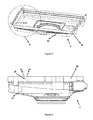
Figure 2 is a perspective illustration of a base part comprised by the washer/dryer device according to the present invention. -
Figure 3 is a side illustration of the base part comprised by the washer/dryer device according to the present invention. -
Figure 4 is a perspective illustration of detail A given inFigure 2 . -
Figure 5 is a perspective illustration of a fixation device according to the present invention. -
Figure 6 is a detailed illustration of the fixation device in a mounted state to the washer/dryer device. -
Figure 7 is a cross-sectional side illustration of the part of the washer/dryer device to which the fixation element is mounted. - The parts in said figures are individually referenced as following.
Body part (1) Lateral wall (1a) Rear wall (1b) Base part (2) Body (2a) Frame part (2b) Support part (2c) Fastening protrusion (2e) Hole (2f) Gap (2g, 3f) Fixation element (3) Base (3a) First leg (3b) Second leg (3c) Third leg (3d) Outer surface (3e) Inclined surface (3g) Inner surface (3h) Connection slot (3j) Connection member (4) - Washer/dryer devices and particularly the dishwashers according to the prior art comprise a body part and a base part, which constitute a washing tub where items to be washed are placed. These parts can either be produced monolithically or separately and assembled afterwards. Various methods such as screwing, gluing and coupling can be used for this assembly process. The present invention, in turn, provides a fixation element which was developed as an alternative to said assembly methods, as well as a washer/dryer device comprising this fixation element.
- The fixation element (3) developed according to the present invention, illustrated in
Figure 5 , is suitable for assembling a body part (1) and a base part (2) together in a washer/dryer device (not illustrated in the figures), comprising at least one body part (1) illustrated inFigure 1 and at least one base part (2), illustrated infigures 2-4 , to which said body part (1) is mounted. Said body part (1) has at least two lateral walls (1 a) and at least one rear wall (1 b), whereas said base part (2) comprises at least one body (2a) preferably with a pool shape, at least one frame part (2b) disposed on at least one upper edge of the body (2a) so as to extend outward along said edge, and at least support part (2c) disposed on said upper edge of the body (2a) on the side of the frame part (2b) facing the body (2) such that at least one gap (2g) is formed between the frame part (2b) and the support part. The lower part of at least one wall (1 a or 1 b) comprised by the body part (1) is placed into said gap (3g) provided in the base part (2) so that the body part (1) and the base part (2) are mounted to each other. This support part (2c) can either be a monolithic part extending along said upper edge, or may have a multipart structure disposed along the upper edge at certain intervals. - The fixation element (3) has a U-shape comprising at least one base (3a); at least one first leg (3b) extending from one corner of the base (3a); at least one second leg (3c) extending in parallel to the first leg (3b) from an opposite corner of said base (3a); and at least one gap (3f) provided between the first leg (3b) and the second leg (3c). The fixation element (3) is further biased to maintain this U-shape and is produced from a flexible material by which said legs (3b, 3c) can be resiliently moved relative to each other. As illustrated in
figures 6 and7 , the fixation element (3) is mounted so that the second leg (3c) is placed in between the frame part (2b) and one wall (lateral wall (1a) or rear wall (1b)) of the body part (1), and the first leg (3b) contacts one outer surface of the frame part (2b) not facing said gap (2g), when the body part (1) is placed into the gap (2g) provided in the base part (2). Accordingly, the fixation element (3) exerts a force on the body part (1) towards the support part (2c), such that the body part (1) becomes wedged between the fixation element (3) and the support part (2c) and fixed. By virtue of the fixation element (3) according to the present invention, the body part (1) and the base part (2) are mounted to each other in a single action, without using any components (e.g. screw) which would cause corrosion and/or deformation. Besides the ease of assembly, the fixation element (3) according to the present invention further enables to disassemble the body part (1) and the base part (2) from each other in an easy manner. - According to a preferred embodiment of the present invention, the fixation element (3) comprises at least one third leg (3d) extending from a free end of the first leg (3b) towards the second leg (3c). When the fixation element (3) is mounted, an inner surface (3h) of this third leg (3d) facing the gap (3f) provided in the fixation element (3) rests against a lower side of the frame part (2b). Thus, a more secure and reliable mounting is ensured for the fixation element (3). Additionally, the body part (1) and the base part (2) are wedged in between the second leg (2c) and the third leg (2d), such that these are tightly mounted to each other. According to this embodiment of the present invention, an outer surface (3e) of the third leg (3d) is provided with a inclined structure to facilitate the mounting of the fixation element (3).
- According to another preferred embodiment of the present invention, at least one inclined surface (3g) is provided on the part of the free end of the second leg (3c) disposed in the fixation element (3) facing the gap (3f) provided therein (3). This inclined surface (3g) exerts force on the body part (1) so that the body part (1) is pressed against the support part (2c) when the second leg (3c) is placed in between the frame part (2b) and the body part (1) and, at the same time, the mounting of the fixation element (3) is facilitated with this inclined surface (3g) making contact with the frame part (2b). This inclined surface (3g) is preferably obtained by means of a chamfering method.
- According to a further preferred embodiment of the present invention, the fixation element (3) comprises at least one concentric connection slot (3j) on each of the first leg (3b) and second leg (3c). According to this embodiment, preferably at least one hole (2f) is provided on the frame part (2b) which is concentric with the connection holes (3j), wherein at least one connection member (4) (illustrated in
Figure 6 ) is mounted to said slots (3j) and hole (2f) so that the fixation element (3) is fixed to the frame part (2b). - In another representative embodiment of the present invention illustrated in the figures, the base (3a) of the fixation element (3) is placed in between at least two fastening protrusions (2e) disposed on the frame part (2b). Thus, any dislocation of the fixation element (3) is prevented when the device is operated and/or transported.
- By virtue of the fixation element (3) developed according to the present invention, the body part (1) and the base part (2) of a washer/dryer device can be assembled in a simple and firm manner. Additionally, the fixation element (3) according to the present invention makes it possible to mount said parts to each other without causing any corrosion and/or deformation.
Claims (13)
- A fixation element (3) suitable for use in assembling a body part (1) and a base part (2) together in a washer/dryer device, said device comprising at least one body part (1) having at least two lateral walls (1 a) and at least one rear wall (1 b); and at least one base part (2) having at least one body (2a), at least one frame part (2b) disposed on at least one upper edge of the body (2a) so as to extend outward along said edge, and at least support part (2c) disposed on said upper edge of the body (2a) on the side of the frame part (2b) facing the body (2) such that at least one gap (2g) is formed between the frame part (2b) and the support part, wherein the body part (1) and the base part (2) are mounted to each other by placing the lower part of at least one wall (1 a or 1 b) comprised by the body part (1) into said gap (2g) provided in the base part (2), characterized by comprising- at least one base (3a);- at least one first leg (3b), extending from one corner of the base (3a) and being disposed so as to contact an outer surface of the frame part (2b) not facing said gap (2g) when the body part (1) is placed into the gap (2g) provided in the base part (2);- at least one second leg (3c), extending in parallel to the first leg (3b) from an opposite corner of said base (3a) and being disposed so as to be placed between one wall (1 a or 1b) of the body part (1) and the frame part (2b) when the body part (1) is placed into the gap (2g) provided in the base part (2); and- at least one gap (3f) disposed between the first leg (3b) and the second leg (3c);wherein said fixation element has a U-shape and is produced from a resilient material by which the fixation element (3) can maintain its U-shape and said legs (3b, 3c) can be resiliently moved relative to each other.
- A fixation element (3) according to Claim 1, characterized by comprising at least one third leg (3d) extending from a free end of the first leg (3b) towards the second leg (3c); and comprising at least one inner surface (3h) facing the gap (3f) provided in the fixation element (3) and resting against a lower side of the frame part (2b) when the fixation element (3) is mounted.
- A fixation element (3) according to Claim 2, characterized in that the outer surface (3e) of the third leg (3d) has an inclined structure.
- A fixation element (3) according to Claim 1, characterized in that the free end of the second leg (3c) comprises at least one inclined surface (3g) on the side thereof facing the gap (3f) provided in the fixation element (3).
- A fixation element (3) according to Claim 1, characterized by comprising at least one connection slot (3j) on each of the first leg (3b) and the second leg (3c).
- A fixation element (3) according to Claim 5, characterized in that said slots (3j) are concentric.
- A washer/dryer device comprising at least one body part (1) having at least two lateral walls (1a) and at least one rear wall (1 b); and at least one base part (2) having at least one body (2a), at least one frame part (2b) disposed on at least one upper edge of the body (2a) so as to extend outward along said edge, and at least support part (2c) disposed on said upper edge of the body (2a) on the side of the frame part (2b) facing the body (2) such that at least one gap (2g) is formed between the frame part (2b) and the support part (2c), wherein the body part (1) and the base part (2) are mounted to each other by placing the lower part of at least one wall (1 a or 1 b) comprised by the body part (1) into said gap (2g) provided in the base part (2), characterized by comprising at least one fixation element (3) according to any of the preceding claims.
- A washer/dryer device according to Claim 7, characterized in that the frame part (2b) comprises at least one hole (2f) on the part thereof where the fixation element (3) is mounted.
- A washer/dryer device according to Claim 8, characterized in that said hole (2f) is concentric with the connection slots (3j) disposed in the fixation element (3).
- A washer/dryer device according to Claim 7, characterized by comprising at least two fastening protrusion (2e) disposed on the frame part (2b), the base (3a) of the fixation element (3) being placed between said fastening protrusions (2e).
- A washer/dryer device according to Claim 7, characterized in that said body (1) has a pool shape.
- A washer/dryer device according to Claim 7, characterized in that said support part (2c) has a monolithic structure extending along said upper edge.
- A washer/dryer device according to Claim 7, characterized in that said support part (2c) has a multipart structure disposed along the upper edge at certain intervals.
Priority Applications (1)
| Application Number | Priority Date | Filing Date | Title |
|---|---|---|---|
| EP13157862.7A EP2774527B1 (en) | 2013-03-05 | 2013-03-05 | A fixation element and a washer/dryer device |
Applications Claiming Priority (1)
| Application Number | Priority Date | Filing Date | Title |
|---|---|---|---|
| EP13157862.7A EP2774527B1 (en) | 2013-03-05 | 2013-03-05 | A fixation element and a washer/dryer device |
Publications (2)
| Publication Number | Publication Date |
|---|---|
| EP2774527A1 true EP2774527A1 (en) | 2014-09-10 |
| EP2774527B1 EP2774527B1 (en) | 2016-02-03 |
Family
ID=48047804
Family Applications (1)
| Application Number | Title | Priority Date | Filing Date |
|---|---|---|---|
| EP13157862.7A Not-in-force EP2774527B1 (en) | 2013-03-05 | 2013-03-05 | A fixation element and a washer/dryer device |
Country Status (1)
| Country | Link |
|---|---|
| EP (1) | EP2774527B1 (en) |
Cited By (4)
| Publication number | Priority date | Publication date | Assignee | Title |
|---|---|---|---|---|
| CN106137079A (en) * | 2015-03-23 | 2016-11-23 | 青岛海尔洗碗机有限公司 | Footing support piece and dish-washing machine before use in dishwasher |
| CN107411686A (en) * | 2017-09-20 | 2017-12-01 | 佛山市顺德区美的洗涤电器制造有限公司 | Dish-washing machine and its base anti-deforming structure |
| CN107411692A (en) * | 2017-09-20 | 2017-12-01 | 佛山市顺德区美的洗涤电器制造有限公司 | Dish-washing machine and its base inserting guide frame |
| CN107550436A (en) * | 2017-09-20 | 2018-01-09 | 佛山市顺德区美的洗涤电器制造有限公司 | One kind washes the dishes machine base support reinforcing structure and dish-washing machine |
Citations (5)
| Publication number | Priority date | Publication date | Assignee | Title |
|---|---|---|---|---|
| JP2004267679A (en) | 2003-03-12 | 2004-09-30 | Matsushita Electric Ind Co Ltd | dishwasher |
| WO2008080933A1 (en) * | 2006-12-29 | 2008-07-10 | Arcelik Anonim Sirketi | A dishwasher |
| US20090211614A1 (en) | 2005-08-29 | 2009-08-27 | Soon Yong Kwon | Dish Washer |
| WO2011161853A1 (en) * | 2010-06-21 | 2011-12-29 | パナソニック株式会社 | Dishwasher |
| DE102010038480A1 (en) * | 2010-07-27 | 2012-02-02 | BSH Bosch und Siemens Hausgeräte GmbH | Household dishwasher for cleaning e.g. goods, has seal integrally formed at base unit, extending between cover- and base units in assembled condition and expanding from base unit towards cover unit |
-
2013
- 2013-03-05 EP EP13157862.7A patent/EP2774527B1/en not_active Not-in-force
Patent Citations (5)
| Publication number | Priority date | Publication date | Assignee | Title |
|---|---|---|---|---|
| JP2004267679A (en) | 2003-03-12 | 2004-09-30 | Matsushita Electric Ind Co Ltd | dishwasher |
| US20090211614A1 (en) | 2005-08-29 | 2009-08-27 | Soon Yong Kwon | Dish Washer |
| WO2008080933A1 (en) * | 2006-12-29 | 2008-07-10 | Arcelik Anonim Sirketi | A dishwasher |
| WO2011161853A1 (en) * | 2010-06-21 | 2011-12-29 | パナソニック株式会社 | Dishwasher |
| DE102010038480A1 (en) * | 2010-07-27 | 2012-02-02 | BSH Bosch und Siemens Hausgeräte GmbH | Household dishwasher for cleaning e.g. goods, has seal integrally formed at base unit, extending between cover- and base units in assembled condition and expanding from base unit towards cover unit |
Cited By (6)
| Publication number | Priority date | Publication date | Assignee | Title |
|---|---|---|---|---|
| CN106137079A (en) * | 2015-03-23 | 2016-11-23 | 青岛海尔洗碗机有限公司 | Footing support piece and dish-washing machine before use in dishwasher |
| CN106137079B (en) * | 2015-03-23 | 2019-09-06 | 青岛海尔洗碗机有限公司 | Front foot support for dishwasher and dishwasher |
| CN107411686A (en) * | 2017-09-20 | 2017-12-01 | 佛山市顺德区美的洗涤电器制造有限公司 | Dish-washing machine and its base anti-deforming structure |
| CN107411692A (en) * | 2017-09-20 | 2017-12-01 | 佛山市顺德区美的洗涤电器制造有限公司 | Dish-washing machine and its base inserting guide frame |
| CN107550436A (en) * | 2017-09-20 | 2018-01-09 | 佛山市顺德区美的洗涤电器制造有限公司 | One kind washes the dishes machine base support reinforcing structure and dish-washing machine |
| CN107411692B (en) * | 2017-09-20 | 2019-05-07 | 佛山市顺德区美的洗涤电器制造有限公司 | Dishwasher and its base insertion guide structure |
Also Published As
| Publication number | Publication date |
|---|---|
| EP2774527B1 (en) | 2016-02-03 |
Similar Documents
| Publication | Publication Date | Title |
|---|---|---|
| US4045104A (en) | Cabinet structure and method of construction | |
| EP2774527A1 (en) | A fixation element and a washer/dryer device | |
| KR101453493B1 (en) | Sectional desk | |
| KR200464099Y1 (en) | Assembly desk | |
| KR101643359B1 (en) | modular desk | |
| KR101208357B1 (en) | Assembling element and table having the same | |
| KR20140005360U (en) | Corner connecting means of draw table | |
| KR200442669Y1 (en) | Fixtures on prefabricated shelves | |
| CN205711436U (en) | A kind of washing machine top case and washing machine | |
| JP2006296790A (en) | Assembly structure | |
| CN109357345B (en) | Humidifying fan | |
| KR20080001391U (en) | Bracket for Drain Pipe and Hanger | |
| KR20090012771U (en) | Cage Nut | |
| JP2014184016A (en) | Leg fixing structure | |
| KR20110027465A (en) | Elastic Fixed Panel | |
| KR100914148B1 (en) | Mounting structure of sink legs | |
| KR100841100B1 (en) | Leg fastening structure of table | |
| KR101729950B1 (en) | A sectional desk | |
| KR100595002B1 (en) | Fastening structure of support | |
| KR200460903Y1 (en) | A Prefabricated Table Mounting Leg Efficiently | |
| KR200473975Y1 (en) | Kickstand of furniture | |
| JP2016000112A (en) | Shelf mounting member | |
| KR101230696B1 (en) | Pcb fixing structure using rib | |
| KR20080053641A (en) | PCB fixing structure by crimping chassis | |
| KR100592762B1 (en) | Case fastening structure of mobile communication terminal |
Legal Events
| Date | Code | Title | Description |
|---|---|---|---|
| PUAI | Public reference made under article 153(3) epc to a published international application that has entered the european phase |
Free format text: ORIGINAL CODE: 0009012 |
|
| 17P | Request for examination filed |
Effective date: 20130305 |
|
| AK | Designated contracting states |
Kind code of ref document: A1 Designated state(s): AL AT BE BG CH CY CZ DE DK EE ES FI FR GB GR HR HU IE IS IT LI LT LU LV MC MK MT NL NO PL PT RO RS SE SI SK SM TR |
|
| AX | Request for extension of the european patent |
Extension state: BA ME |
|
| R17P | Request for examination filed (corrected) |
Effective date: 20150310 |
|
| GRAP | Despatch of communication of intention to grant a patent |
Free format text: ORIGINAL CODE: EPIDOSNIGR1 |
|
| INTG | Intention to grant announced |
Effective date: 20150917 |
|
| GRAS | Grant fee paid |
Free format text: ORIGINAL CODE: EPIDOSNIGR3 |
|
| GRAA | (expected) grant |
Free format text: ORIGINAL CODE: 0009210 |
|
| AK | Designated contracting states |
Kind code of ref document: B1 Designated state(s): AL AT BE BG CH CY CZ DE DK EE ES FI FR GB GR HR HU IE IS IT LI LT LU LV MC MK MT NL NO PL PT RO RS SE SI SK SM TR |
|
| REG | Reference to a national code |
Ref country code: GB Ref legal event code: FG4D |
|
| REG | Reference to a national code |
Ref country code: AT Ref legal event code: REF Ref document number: 773267 Country of ref document: AT Kind code of ref document: T Effective date: 20160215 Ref country code: CH Ref legal event code: EP |
|
| REG | Reference to a national code |
Ref country code: IE Ref legal event code: FG4D |
|
| REG | Reference to a national code |
Ref country code: DE Ref legal event code: R096 Ref document number: 602013004839 Country of ref document: DE |
|
| REG | Reference to a national code |
Ref country code: FR Ref legal event code: PLFP Year of fee payment: 4 |
|
| REG | Reference to a national code |
Ref country code: LT Ref legal event code: MG4D Ref country code: NL Ref legal event code: MP Effective date: 20160203 |
|
| REG | Reference to a national code |
Ref country code: AT Ref legal event code: MK05 Ref document number: 773267 Country of ref document: AT Kind code of ref document: T Effective date: 20160203 |
|
| PG25 | Lapsed in a contracting state [announced via postgrant information from national office to epo] |
Ref country code: NO Free format text: LAPSE BECAUSE OF FAILURE TO SUBMIT A TRANSLATION OF THE DESCRIPTION OR TO PAY THE FEE WITHIN THE PRESCRIBED TIME-LIMIT Effective date: 20160503 Ref country code: IT Free format text: LAPSE BECAUSE OF FAILURE TO SUBMIT A TRANSLATION OF THE DESCRIPTION OR TO PAY THE FEE WITHIN THE PRESCRIBED TIME-LIMIT Effective date: 20160203 Ref country code: GR Free format text: LAPSE BECAUSE OF FAILURE TO SUBMIT A TRANSLATION OF THE DESCRIPTION OR TO PAY THE FEE WITHIN THE PRESCRIBED TIME-LIMIT Effective date: 20160504 Ref country code: FI Free format text: LAPSE BECAUSE OF FAILURE TO SUBMIT A TRANSLATION OF THE DESCRIPTION OR TO PAY THE FEE WITHIN THE PRESCRIBED TIME-LIMIT Effective date: 20160203 Ref country code: ES Free format text: LAPSE BECAUSE OF FAILURE TO SUBMIT A TRANSLATION OF THE DESCRIPTION OR TO PAY THE FEE WITHIN THE PRESCRIBED TIME-LIMIT Effective date: 20160203 Ref country code: HR Free format text: LAPSE BECAUSE OF FAILURE TO SUBMIT A TRANSLATION OF THE DESCRIPTION OR TO PAY THE FEE WITHIN THE PRESCRIBED TIME-LIMIT Effective date: 20160203 |
|
| PG25 | Lapsed in a contracting state [announced via postgrant information from national office to epo] |
Ref country code: PT Free format text: LAPSE BECAUSE OF FAILURE TO SUBMIT A TRANSLATION OF THE DESCRIPTION OR TO PAY THE FEE WITHIN THE PRESCRIBED TIME-LIMIT Effective date: 20160603 Ref country code: SE Free format text: LAPSE BECAUSE OF FAILURE TO SUBMIT A TRANSLATION OF THE DESCRIPTION OR TO PAY THE FEE WITHIN THE PRESCRIBED TIME-LIMIT Effective date: 20160203 Ref country code: LT Free format text: LAPSE BECAUSE OF FAILURE TO SUBMIT A TRANSLATION OF THE DESCRIPTION OR TO PAY THE FEE WITHIN THE PRESCRIBED TIME-LIMIT Effective date: 20160203 Ref country code: NL Free format text: LAPSE BECAUSE OF FAILURE TO SUBMIT A TRANSLATION OF THE DESCRIPTION OR TO PAY THE FEE WITHIN THE PRESCRIBED TIME-LIMIT Effective date: 20160203 Ref country code: LV Free format text: LAPSE BECAUSE OF FAILURE TO SUBMIT A TRANSLATION OF THE DESCRIPTION OR TO PAY THE FEE WITHIN THE PRESCRIBED TIME-LIMIT Effective date: 20160203 Ref country code: AT Free format text: LAPSE BECAUSE OF FAILURE TO SUBMIT A TRANSLATION OF THE DESCRIPTION OR TO PAY THE FEE WITHIN THE PRESCRIBED TIME-LIMIT Effective date: 20160203 Ref country code: BE Free format text: LAPSE BECAUSE OF NON-PAYMENT OF DUE FEES Effective date: 20160331 Ref country code: IS Free format text: LAPSE BECAUSE OF FAILURE TO SUBMIT A TRANSLATION OF THE DESCRIPTION OR TO PAY THE FEE WITHIN THE PRESCRIBED TIME-LIMIT Effective date: 20160603 Ref country code: RS Free format text: LAPSE BECAUSE OF FAILURE TO SUBMIT A TRANSLATION OF THE DESCRIPTION OR TO PAY THE FEE WITHIN THE PRESCRIBED TIME-LIMIT Effective date: 20160203 Ref country code: PL Free format text: LAPSE BECAUSE OF FAILURE TO SUBMIT A TRANSLATION OF THE DESCRIPTION OR TO PAY THE FEE WITHIN THE PRESCRIBED TIME-LIMIT Effective date: 20160203 |
|
| REG | Reference to a national code |
Ref country code: DE Ref legal event code: R119 Ref document number: 602013004839 Country of ref document: DE |
|
| PG25 | Lapsed in a contracting state [announced via postgrant information from national office to epo] |
Ref country code: EE Free format text: LAPSE BECAUSE OF FAILURE TO SUBMIT A TRANSLATION OF THE DESCRIPTION OR TO PAY THE FEE WITHIN THE PRESCRIBED TIME-LIMIT Effective date: 20160203 Ref country code: DK Free format text: LAPSE BECAUSE OF FAILURE TO SUBMIT A TRANSLATION OF THE DESCRIPTION OR TO PAY THE FEE WITHIN THE PRESCRIBED TIME-LIMIT Effective date: 20160203 |
|
| REG | Reference to a national code |
Ref country code: CH Ref legal event code: PL |
|
| PG25 | Lapsed in a contracting state [announced via postgrant information from national office to epo] |
Ref country code: RO Free format text: LAPSE BECAUSE OF FAILURE TO SUBMIT A TRANSLATION OF THE DESCRIPTION OR TO PAY THE FEE WITHIN THE PRESCRIBED TIME-LIMIT Effective date: 20160203 Ref country code: SK Free format text: LAPSE BECAUSE OF FAILURE TO SUBMIT A TRANSLATION OF THE DESCRIPTION OR TO PAY THE FEE WITHIN THE PRESCRIBED TIME-LIMIT Effective date: 20160203 Ref country code: CZ Free format text: LAPSE BECAUSE OF FAILURE TO SUBMIT A TRANSLATION OF THE DESCRIPTION OR TO PAY THE FEE WITHIN THE PRESCRIBED TIME-LIMIT Effective date: 20160203 Ref country code: SM Free format text: LAPSE BECAUSE OF FAILURE TO SUBMIT A TRANSLATION OF THE DESCRIPTION OR TO PAY THE FEE WITHIN THE PRESCRIBED TIME-LIMIT Effective date: 20160203 |
|
| PLBE | No opposition filed within time limit |
Free format text: ORIGINAL CODE: 0009261 |
|
| STAA | Information on the status of an ep patent application or granted ep patent |
Free format text: STATUS: NO OPPOSITION FILED WITHIN TIME LIMIT |
|
| REG | Reference to a national code |
Ref country code: IE Ref legal event code: MM4A |
|
| PG25 | Lapsed in a contracting state [announced via postgrant information from national office to epo] |
Ref country code: BE Free format text: LAPSE BECAUSE OF FAILURE TO SUBMIT A TRANSLATION OF THE DESCRIPTION OR TO PAY THE FEE WITHIN THE PRESCRIBED TIME-LIMIT Effective date: 20160203 |
|
| 26N | No opposition filed |
Effective date: 20161104 |
|
| REG | Reference to a national code |
Ref country code: FR Ref legal event code: PLFP Year of fee payment: 5 |
|
| PG25 | Lapsed in a contracting state [announced via postgrant information from national office to epo] |
Ref country code: LI Free format text: LAPSE BECAUSE OF NON-PAYMENT OF DUE FEES Effective date: 20160331 Ref country code: CH Free format text: LAPSE BECAUSE OF NON-PAYMENT OF DUE FEES Effective date: 20160331 Ref country code: DE Free format text: LAPSE BECAUSE OF NON-PAYMENT OF DUE FEES Effective date: 20161001 Ref country code: IE Free format text: LAPSE BECAUSE OF NON-PAYMENT OF DUE FEES Effective date: 20160305 |
|
| PG25 | Lapsed in a contracting state [announced via postgrant information from national office to epo] |
Ref country code: BG Free format text: LAPSE BECAUSE OF FAILURE TO SUBMIT A TRANSLATION OF THE DESCRIPTION OR TO PAY THE FEE WITHIN THE PRESCRIBED TIME-LIMIT Effective date: 20160503 Ref country code: SI Free format text: LAPSE BECAUSE OF FAILURE TO SUBMIT A TRANSLATION OF THE DESCRIPTION OR TO PAY THE FEE WITHIN THE PRESCRIBED TIME-LIMIT Effective date: 20160203 |
|
| PG25 | Lapsed in a contracting state [announced via postgrant information from national office to epo] |
Ref country code: MT Free format text: LAPSE BECAUSE OF FAILURE TO SUBMIT A TRANSLATION OF THE DESCRIPTION OR TO PAY THE FEE WITHIN THE PRESCRIBED TIME-LIMIT Effective date: 20160203 |
|
| GBPC | Gb: european patent ceased through non-payment of renewal fee |
Effective date: 20170305 |
|
| PG25 | Lapsed in a contracting state [announced via postgrant information from national office to epo] |
Ref country code: GB Free format text: LAPSE BECAUSE OF NON-PAYMENT OF DUE FEES Effective date: 20170305 |
|
| REG | Reference to a national code |
Ref country code: FR Ref legal event code: PLFP Year of fee payment: 6 |
|
| PG25 | Lapsed in a contracting state [announced via postgrant information from national office to epo] |
Ref country code: HU Free format text: LAPSE BECAUSE OF FAILURE TO SUBMIT A TRANSLATION OF THE DESCRIPTION OR TO PAY THE FEE WITHIN THE PRESCRIBED TIME-LIMIT; INVALID AB INITIO Effective date: 20130305 Ref country code: CY Free format text: LAPSE BECAUSE OF FAILURE TO SUBMIT A TRANSLATION OF THE DESCRIPTION OR TO PAY THE FEE WITHIN THE PRESCRIBED TIME-LIMIT Effective date: 20160203 |
|
| PGFP | Annual fee paid to national office [announced via postgrant information from national office to epo] |
Ref country code: TR Payment date: 20180214 Year of fee payment: 6 |
|
| PG25 | Lapsed in a contracting state [announced via postgrant information from national office to epo] |
Ref country code: LU Free format text: LAPSE BECAUSE OF NON-PAYMENT OF DUE FEES Effective date: 20160305 Ref country code: MT Free format text: LAPSE BECAUSE OF FAILURE TO SUBMIT A TRANSLATION OF THE DESCRIPTION OR TO PAY THE FEE WITHIN THE PRESCRIBED TIME-LIMIT Effective date: 20160331 Ref country code: MK Free format text: LAPSE BECAUSE OF FAILURE TO SUBMIT A TRANSLATION OF THE DESCRIPTION OR TO PAY THE FEE WITHIN THE PRESCRIBED TIME-LIMIT Effective date: 20160203 Ref country code: MC Free format text: LAPSE BECAUSE OF FAILURE TO SUBMIT A TRANSLATION OF THE DESCRIPTION OR TO PAY THE FEE WITHIN THE PRESCRIBED TIME-LIMIT Effective date: 20160203 |
|
| PG25 | Lapsed in a contracting state [announced via postgrant information from national office to epo] |
Ref country code: AL Free format text: LAPSE BECAUSE OF FAILURE TO SUBMIT A TRANSLATION OF THE DESCRIPTION OR TO PAY THE FEE WITHIN THE PRESCRIBED TIME-LIMIT Effective date: 20160203 |
|
| PGFP | Annual fee paid to national office [announced via postgrant information from national office to epo] |
Ref country code: FR Payment date: 20190322 Year of fee payment: 7 |
|
| PG25 | Lapsed in a contracting state [announced via postgrant information from national office to epo] |
Ref country code: FR Free format text: LAPSE BECAUSE OF NON-PAYMENT OF DUE FEES Effective date: 20200331 |
|
| PG25 | Lapsed in a contracting state [announced via postgrant information from national office to epo] |
Ref country code: TR Free format text: LAPSE BECAUSE OF NON-PAYMENT OF DUE FEES Effective date: 20190305 |