EP2774290B1 - Taktsynchronisierung bei gemeinsam genutzten basisband-einsatz - Google Patents
Taktsynchronisierung bei gemeinsam genutzten basisband-einsatz Download PDFInfo
- Publication number
- EP2774290B1 EP2774290B1 EP12799605.6A EP12799605A EP2774290B1 EP 2774290 B1 EP2774290 B1 EP 2774290B1 EP 12799605 A EP12799605 A EP 12799605A EP 2774290 B1 EP2774290 B1 EP 2774290B1
- Authority
- EP
- European Patent Office
- Prior art keywords
- rec
- synchronization
- timing
- source
- clock signal
- Prior art date
- Legal status (The legal status is an assumption and is not a legal conclusion. Google has not performed a legal analysis and makes no representation as to the accuracy of the status listed.)
- Active
Links
Images



Classifications
-
- H—ELECTRICITY
- H04—ELECTRIC COMMUNICATION TECHNIQUE
- H04J—MULTIPLEX COMMUNICATION
- H04J3/00—Time-division multiplex systems
- H04J3/02—Details
- H04J3/06—Synchronising arrangements
- H04J3/0635—Clock or time synchronisation in a network
- H04J3/0685—Clock or time synchronisation in a node; Intranode synchronisation
- H04J3/0688—Change of the master or reference, e.g. take-over or failure of the master
Definitions
- the present application relates generally to clock synchronization and, more specifically, to clock synchronization in shared baseband deployments.
- the time period that a network is able to maintain time and sync stability without a reference is called the holdover time.
- Precise synchronization is especially critical in mobile networks for the successful call signal handoff and proper transmission between base stations, as well as for the transport of real-time services. If individual base stations drift outside the specified frequencies, mobile handoff performance decays, calls interfere, and calls cannot be made, resulting in high dropped-call rates and impaired data services. In the event that timing or synchronization reference is temporarily lost, a network's ability to maintain time or "holdover" becomes critical to ensure optimal network performance.
- a distributed radio base station includes a first radio equipment controller (REC) node, a second radio equipment controller (REC) node, and a radio equipment (RE) node for transceiving information over a radio interface with one or more radio terminals.
- the first REC node and the second REC node are employed to service radio communications based on different radio wireless standards and are physically separate from the RE node.
- the first REC node and the second REC node are connected to the RE node by a transmission link. Synchronization reference information is provided to one of the REC and RE nodes.
- the synchronization reference information in the one node is compared with timing information received from another of the REC nodes to generate a timing difference.
- the timing difference is used to adjust a timing unit at the another node in order to achieve timing synchronization between the RE node, the first REC node, and the second REC node.
- the present invention is directed to alleviating the problems of the prior art.
- the present invention overcomes the problems of the prior art by providing a method of synchronization wherein synchronization is provided from one system to the other by recovering a clock from one system's output, then using that synchronization to regenerate a synchronization source for the other system.
- This allows synchronization between systems to be maintained even in the case where the input synchronization source is lost.
- the timing source of one system starts to drift with the lost of a GPS signal, the second system will drift along with it such that the timing remains consistent between the two networks.
- a method of providing timing synchronization between a first Radio Equipment Controller (REC) operating on a first radio standard and a second REC operating on a second radio standard Each REC operates with a multi-standard radio.
- a synchronization signal is received from a first synchronization source at the first RCE and a synchronized data output derived from the synchronization signal is generated.
- a first clock signal is generated from the synchronized data output for use by the first RCE.
- a synchronization source is then reconstructed from the first clock signal.
- a timing and frequency component of a second clock signal for use by the second REC is then aligned to that of the reconstructed synchronization source, such that the second REC can maintain timing synchronization with the first REC.
- REC Radio Equipment Controller
- Each REC operates with a multi-standard radio.
- the system comprises the first REC for receiving a synchronization signal from a first synchronization source and first synchronization means for generating a synchronized data output derived from the synchronization signal.
- a second synchronization means is used for generating a first clock signal from the synchronized data output for use by the first RCE and first means for reconstructing a synchronization source from said first clock signal is provided.
- the system further comprises second means for aligning a timing and frequency component of a second clock signal for use by the second REC to that of the reconstructed synchronization source, such that the second REC can maintain timing synchronization with the first REC.
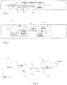
- a timing source 100 such as GPS signal creates an ES (even second) mark 101 synchronized to GPS time, along with an associated (phase-locked) clock 102. It provides these signals to the 2G/3G Data generation equipment 103, which uses them to generate the required codes with an advance with respect to this mark. The amount of this advance is determined by the delay of the radio and the optical fibre - the BaseBand Link 104 to the radio equipment 105.
- a Radio Equipment Controller (REC) 200 is connected to the Radio Equipment (RE) 201 via a Baseband link 202.
- the REC likewise has a time alignment requirement, although this is only for (TDD) time division duplex mode.
- the REC 200 receives a GPS timing reference consisting of a PPS (pulse per second) signal 203 and associated clock 204. These signals are used to generate the framing information for the Baseband link.
- PPS pulse per second
- a local timing reference is created. An offset needs to be applied to this timing reference to make it match up with the REC time.
- the REC measures the delay of the Baseband link.
- the radio equipment tells the REC what its delay is. The REC then sends a message to the radio to tell it how much to advance it's time base, and where to find the first sample of the downlink (DL) frame in the baseband frame.
- FIG. 3 we have shown a block diagram illustrating a high level topology of a multi-standard base station radio system according to the present invention.
- the radio system is comprised of a 2G/3G REC 300 which, as an example, may continue to be serviced by a wireless operator wanting to maintain a 2G/3G network but considering expanding its network to include 4G services.
- the 2G/3G REC continues to receive timing signals from a GPS Time Source 301.
- An interface 302, hereinafter referred to as a multiplexer unit (MU) is provided as an interface that provides the ability to co-locate 4G traffic with 2G/3G traffic on a shared radio 303.
- MU multiplexer unit
- one of the requirements for this configuration is that timing must be consistent between the two networks. Since both networks use separate GPS sources for timing, there is a need for a common synchronization between the 2G/3G REC 300 and the 4G REC 306.
- the 2G/3G REC generates its timing source on one baseband link 304 whereas the 4G REC makes use another baseband link 305 but both are intended to share a common multi mode radio 303.
- a problem can exist when the GPS signal or sync of one source is lost or unavailable. Timing signal drift is enough to cause FIFO overflow problems.
- synchronization can be achieved by linking the timing between the 2G/3G REC 300 and the 4G REC 306.
- the MU is used to co-locate CDMA traffic with LTE traffic. It will be understood to those knowledgeable in the art that 2G/3G traffic other than CDMA can also be co-located with an LTE or other 4G traffic according to the teachings of the present invention.
- HSSL High Speed Serial Link
- CPRI Common Public Radio Interface
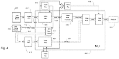
- FIG. 4 we have shown a block diagram of the MU 400, which is used as interface between the CDMA REC and LTE REC to synchronize the timing between the baseband units.
- a GPS source 401 provides an ES (even second) mark synchronized to GPS time to CDMA REC 402.
- GPS source 401 makes use of a received satellite GPS signal to generate a phase-locked clock signal.
- An HSSL baseband link 403 is generated using this clock.
- the VCXO PLL 415 is locked to the CDMA clocking and a 1PPS signal is derived from the VCXO, block 413.
- a 1 PPS signal is output at the rate of 1 pulse per second every 1 second.
- This reference clock signal is fed to the HSSL PHY 404 to create an HSSL rate 405 with VCXO PLL 415 at the egress side the HSSL PHY. It is also used as the reference clock 416 on the radio side.
- the actual rate which would be coming out from the fixed rate re-sampling block 406 could vary and also affect the CPRI rate 407 coming from the CPRI PHY 408 by an amount related to the difference in the timing.
- the GPS source 409 normally connected to the LTE DEC 410 is instead connected to the MU 400, and the MU connects via link 411 to the LTE DEC 410 on the port normally used by GPS source 409 to provide the 1PPS and NMEA messages directly.
- the MU 400 has the ability to select the incoming pulse it wants to use from one of two possible sources, one from a synthetic PPS recovered from the HSSL baseband link 403 and one from the GPS source 409. As will be explained further below, this selection will depend on the condition of the clock source and the timing difference between the various pulses.
- a set of NMEA messages 412 is received from the GPS source 409 in addition to the 1PPS pulse. This is accomplished by passing the NMEA messages 412 from the GPS source 409 to the LTE DEC 410 via a GPS Emulation block 413.
- the data in the messages passed through are cached in case the GPS fails in some way and stops sending messages.
- the system software is responsible for caching the nmea messages which are logically cached in block 413 even though Fig. 4 is more of a hardware block diagram.
- the MU 400 can choose to generate the 1PPS to the LTE DEC 410 either from the connected GPS source 409 or using a synthetic 1PPS generated from the HSSL baseband link timing 403.
- the HSSL source is preferred over the GPS source (once the phase of the HSSL source is aligned with the GPS), if the HSSL source 403 fails, the MU will make use of the GPS timing source 409. If the HSSL timing source 403 starts to drift, the CPRI side will drift along with it since one is synchronized with the other.
- HSSL timing 403 is preferred, as using it allows for consistent timing between the CDMA DEC 402 and LTE DEC 410, even if the CDMA DEC 402 goes into holdover mode and drifts (the LTE DEC 410 will follow the drift).
- the selected timing will be output to the radios 414 with the CPRI baseband link that carries the data for both the CDMA and LTE networks.
- a 1PPS source at link 411 is generated artificially via a synthetic pulse generated by GPS Emulation block 413. This pulse will be based on the timing signal received from the HSSL links 403.
- a synthetic 1PPS is generated at GPS Emulation block 413 using the PLL 415 that is locked to the HSSL link 403.
- the GPS Emulation block 413 provides a set of registers that can be used to measure the phase offset between the 1PPS 412 of the GPS source 409 (if available) and the synthetic 1PPS.
- the steady state behavior of the system is to derive the timing from the HSSL link 403.
- the system will align the phase of the HSSL-derived synthetic PPS 403 and the GPS PPS 412 and then switch over to use the synthetic PPS for timing. It will continue to do so unless a clock signal failure occurs, in which case a different timing source will be used as will be explained further below.
- the recovered clock from the HSSL recovers rate and not phase.
- the synthetic PPS is aligned to the incoming GPS PPS.
- the synthetic PPS is issued based on a down-counter located in the GPS emulation block 413. This counter is timed from the VCXO that is locked to the incoming HSSL clock rate (415 in Fig. 4 ).
- the counter counts from 0x79dfff to 0. When the counter reaches 0x3cf0000 the synthetic pps is emitted ("PPS Output Time”) .
- the value of the down-counter is written to the gps offset register in the GPS emulation block 413.
- a 1 is written to the most significant bit, and the previous most significant bit is copied to the second-most significant bit.
- Fig. 5a GPS source is initialized
- Fig. 5b HSSL startup
- Fig. 5c holdover timing caused by HSSL link failure
- Fig. 5d LTE REC reset
- Fig. 5f CDMA REC holdover
- Fig. 5g GPS source failure.
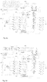
- Fig. 5a we have shown the timing flow after the GPS source 606 has been initialized. In this case, there is no HSSL timing (paths 600) available from the CDMA side of the network.
- the GPS reference signal 605 is derived from GPS source 606 for the LTE REC 611.
- Fig. 5b illustrates the timing flow as the system switches from using the GPS source reference 1PPS clock signal 605 to using the HSSL-derived synthetic PPS clock signals 604. This can be thought of as part 2 of the initialization sequence.
- the initial procedure of switching to the synthetic 1PPS 604 is to line up the synthetic 1PPS with the reference 1PPS clock signal 605 of the GPS source 606.
- the timing switches to the synthetic 1PPS and the CPRI clock selection switches to use the HSSL-derived synthetic PPS clock signals 600 for the timing on the CPRI links 603 to the radios. If during the measurement phase the HSSL links 600 are lost, the switchover to HSSL for timing is aborted.
- the switchover to HSSL for timing is aborted also. In this case there will no longer be a 1PPS signal going to the LTE REC 611, and the LTE REC 611 will be in holdover. If the LTE REC 611 resets during this switchover process, the switchover is not affected.
- Fig. 5c illustrates a failure of the HSSL link 600 and in particular the timing that may occur immediately after, when the LTE REC 611 enters holdover.
- the system will switch back to either the GPS source reference 1PPS signal 605 if that signal has not drifted in relation to the lost HSSL signal timing 600, that is, the timing on the CDMA REC links 600 had remained aligned to the GPS source reference 1PPS. Otherwise, the LTE REC 611 will enter holdover for a while and base its timing on its OCXO 612. This will continue until its algorithm changes the GPS source reference 1PPS signal and begins to accept it.
- the CPRI clock signal 603 will be based on the timing generated from the LTE REC CPRI links 615.
- Fig. 5d illustrates the timing when the LTE REC 611 is reset.
- the reset of the LTE REC does not impact the timing of the HSSL clock signal paths 600 through to the radios.
- the only difference is that the NMEA messages from the GPS source 606 and the synthetic 1PPS 610 sent to the LTE REC 611 do not arrive.
- the LTE REC recovers, it will continue on as normal, receiving the 1PPS timing from the MU and driving the CPRI link timing for the CPRI links between the LTE REC and MU.
- Fig. 5e illustrates the timing flow when the LTE REC goes into holdover. This can occur when the synthetic GPS signal 610 fails at the LTE REC. Another scenario is if the HSSL clock signal 600 has drifted, then failed (as illustrated in Fig. 6c) and the GPS source reference 1PPS signal 610 is rejected thus forcing the LTE REC to go into holdover.
- the timing from the LTE REC would differ from the HSSL timing being used to drive the HSSL links. This would result in FIFO overflows and the LTE traffic would be shut down.
- Fig. 5f illustrates the timing flow when the CDMA REC goes into holdover. This is detectable by monitoring the signal drift with the GPS source reference 1PPS signal.
- the fault should be cleared - except in the scenario where CDMA was in holdover when the MU switched to HSSL for timing.
- the phase of the PPS going to the LTE REC will differ from the GPS signal. The phase will then need to be lined up for the recovered HSSL clock.
- Fig. 5g illustrates the situation when the signal from GPS source 606 is lost.
- GPS failure while HSSL is being used to drive the timing is not a critical failure - the NMEA messages sent by the GPS source 606 are cached in the MU and continue to be forwarded to the LTE REC.
- the exception is drift.
- drift on the HSSL timing cannot be detected. This scenario may happen if, say for example, the GPS antenna, being used by the CDMA unit and the GPS source 606 connected to the MU, stops working.
- the GPS source 606 connected to the MU will stop emitting reference 1PPS signal and the CDMA unit will go into holdover.
- the present invention can be realized in hardware, or a combination of hardware and software. Any kind of computing system, or other apparatus adapted for carrying out the methods described herein, is suited to perform the functions described herein.
- a typical combination of hardware and software could be a specialized computer system, e.g., a router, having one or more processing elements and a computer program stored on a storage medium that, when loaded and executed, controls the computer system such that it carries out the methods described herein.
- the present invention can also be embedded in a computer program product, which comprises all the features enabling the implementation of the methods described herein, and which, when loaded in a computing system is able to carry out these methods.
- Storage medium refers to any volatile or nonvolatile storage device.
- Computer program or application in the present context means any expression, in any language, code or notation, of a set of instructions intended to cause a system having an information processing capability to perform a particular function either directly or after either or both of the following a) conversion to another language, code or notation; b) reproduction in a different material form.
- one embodiment is a computer readable medium containing computer readable instruction that, when executed by a processor, cause the processor to perform functions for maintaining clock synchronization between a first and a second radio.
Landscapes
- Engineering & Computer Science (AREA)
- Computer Networks & Wireless Communication (AREA)
- Signal Processing (AREA)
- Synchronisation In Digital Transmission Systems (AREA)
- Mobile Radio Communication Systems (AREA)
- Position Fixing By Use Of Radio Waves (AREA)
Claims (10)
- Verfahren zum Bereitstellen einer Zeitsteuerungssynchronisation zwischen einer ersten Funkausrüstungssteuerung (REC, 300, 402), die gemäß einem ersten Funkstandard betrieben wird, und einer zweiten REC (306, 410), die gemäß einem zweiten Funkstandard betrieben wird, wobei jede REC mit einer Multi-Standard-Funkeinheit (303, 414) betrieben wird, umfassend die Schritte:Empfangen, an der ersten REC (300, 402), eines Synchronisationssignals von einer ersten Synchronisationsquelle (401);Erzeugen einer synchronisierten Datenausgabe, die aus dem Synchronisationssignal abgeleitet wurde;Erzeugen eines ersten Taktsignals aus der synchronisierten Datenausgabe zur Verwendung durch die erste REC (300, 402);Rekonstruieren einer Synchronisationsquelle aus dem ersten Taktsignal; und gekennzeichnet durchAngleichen einer Zeitsteuerungs- und Frequenzkomponente eines zweiten Taktsignals zur Verwendung durch die zweite REC (306, 410) an diejenige der rekonstruierten Synchronisationsquelle derart, dass die zweite REC (306, 410) mit der ersten REC (300, 402) eine Zeitsteuerungssynchronisation aufrechterhalten kann.
- Verfahren nach Anspruch 1, ferner umfassend:Weiterleiten der synchronisierten Datenausgabe zu einem Zeitsteuerungs-Quell-Emulator (413); undErzeugen des zweiten Taktsignals aus einer zweiten Synchronisationsquelle.
- Verfahren nach Anspruch 1 oder 2, ferner umfassend den Schritt eines Speicherns von Zeitsteuerungspulsen, die der synchronisierten Datenausgabe zugeordnet sind.
- Verfahren nach Anspruch 3, ferner umfassend den Schritt eines Emulierens der Synchronisationsquelle in Abhängigkeit der gespeicherten Zeitsteuerungspulsen.
- System zum Bereitstellen einer Zeitsteuerungssynchronisation zwischen einer ersten Funkausrüstungssteuerung (REC, 300, 402), die gemäß einem ersten Funkstandard betrieben wird, und einer zweiten REC (306, 410), die gemäß einem zweiten Funkstandard betrieben wird, wobei jede REC mit einer Multi-Standard-Funkeinheit (303, 414) betrieben wird, umfassend:die erste REC (300, 402) zum Empfangen eines Synchronisationssignals von einer ersten Synchronisationsquelle (401)erste Synchronisationsmittel (401) zum Erzeugen einer synchronisierten Datenausgabe, die aus dem Synchronisationssignal abgeleitet wurde;zweite Synchronisationsmittel (404) zum Erzeugen eines ersten Taktsignals aus der synchronisierten Datenausgabe zur Verwendung durch die erste REC (300, 402);erste Mittel (415) zum Rekonstruieren einer Synchronisationsquelle aus dem ersten Taktsignal; und gekennzeichnet durchzweite Mittel (413) zum Angleichen einer Zeitsteuerungs- und Frequenzkomponente eines zweiten Taktsignals zur Verwendung durch die zweite REC (306, 410) an diejenige der rekonstruierten Synchronisationsquelle derart, dass die zweite REC (306, 410) mit der ersten REC (300, 402) eine Zeitsteuerungssynchronisation aufrechterhalten kann.
- System nach Anspruch 5, wobei die zweite REC (306, 410) eine zweite Synchronisationsquelle (307, 409) aufweist;
wobei die zweiten Synchronisationsmittel (404) auch ausgebildet sind zum Empfangen eines ersten Taktsignals, das der ersten Synchronisationsquelle (301, 401) zugeordnet ist; und
wobei die zweiten Mittel (413) auch ausgebildet sind zum Empfangen eines zweiten Taktsignals von der zweiten Synchronisationsquelle (307, 409);
wobei das System ferner umfasst:
einen Multiplexer (302, 400), der mit der ersten und der zweiten REC (300, 306, 402, 410) verbunden ist, wobei der Multiplexer (302, 400) ausgebildet ist zum Überwachen der ersten und zweiten Synchronisationsquelle (301, 307, 401, 409) und wobei der Multiplexer (302, 400) die Synchronisationsmittel (404) und die zweiten Mittel (413) aufweist. - System nach Anspruch 5 oder 6, wobei die zweiten Mittel (413) ferner einen Speicher zum Speichern von Zeitsteuerungspulsen, die der synchronisierten Datenausgebe zugeordnet sind, umfasst.
- System nach Anspruch 7, wobei die zweiten Mittel (413) die Synchronisationsquelle in Abhängigkeit der gespeicherten Zeitsteuerungspulsen emulieren, wenn die erste Synchronisationsquelle versagt.
- System nach Anspruch 8, wenn abhängig von Anspruch 6, wobei die zweiten Mittel (413) ausgebildet sind zum Messen von Taktsignalversätzen zwischen der ersten und zweiten Synchronisationsquelle (300, 306, 402, 410) zum Bestimmen, ob die erste Synchronisationsquelle (300, 402) bezüglich der zweiten Synchronisationsquelle (305, 410) abweicht.
- System nach Anspruch 9, wobei die zweiten Mittel (413) ausgebildet ist zum Auslösen eines neuen Synchronisationstaktsignals, falls die zweiten Mittel (413) ein Taktsignalabweichen zwischen der ersten und zweiten Synchronisationsquellen (300, 306, 402, 410) erfassen.
Applications Claiming Priority (2)
| Application Number | Priority Date | Filing Date | Title |
|---|---|---|---|
| US13/287,364 US8537948B2 (en) | 2011-11-02 | 2011-11-02 | Clock synchronization in shared baseband deployments |
| PCT/IB2012/055810 WO2013064937A1 (en) | 2011-11-02 | 2012-10-22 | Clock synchronization in shared baseband deployments |
Publications (2)
| Publication Number | Publication Date |
|---|---|
| EP2774290A1 EP2774290A1 (de) | 2014-09-10 |
| EP2774290B1 true EP2774290B1 (de) | 2018-07-25 |
Family
ID=47356232
Family Applications (1)
| Application Number | Title | Priority Date | Filing Date |
|---|---|---|---|
| EP12799605.6A Active EP2774290B1 (de) | 2011-11-02 | 2012-10-22 | Taktsynchronisierung bei gemeinsam genutzten basisband-einsatz |
Country Status (3)
| Country | Link |
|---|---|
| US (1) | US8537948B2 (de) |
| EP (1) | EP2774290B1 (de) |
| WO (1) | WO2013064937A1 (de) |
Families Citing this family (13)
| Publication number | Priority date | Publication date | Assignee | Title |
|---|---|---|---|---|
| US8619936B2 (en) * | 2012-04-11 | 2013-12-31 | Telefonaktiebolaget L M Ericsson (Publ) | Clock switching algorithm based on preferred clock source |
| US20150009834A1 (en) * | 2013-07-08 | 2015-01-08 | Qualcomm Incorporated | Generation of timing pulses based on acquired synchronization |
| WO2015094045A1 (en) | 2013-12-18 | 2015-06-25 | Telefonaktiebolaget L M Ericsson (Publ) | Operation of a multi-standard base station site supporting at least two different radio access technologies |
| US9521636B2 (en) | 2014-04-22 | 2016-12-13 | Nxp Usa, Inc. | Synchronization circuitry, common public radio interface enable device, and a method of synchronizing a synchronized clock signal of a second transceiver to a clock of a first transceiver |
| US9094908B1 (en) * | 2014-04-22 | 2015-07-28 | Freescale Semiconductor, Inc. | Device and method for synchronization in a mobile communication system |
| KR101596756B1 (ko) * | 2014-11-03 | 2016-03-07 | 현대자동차주식회사 | 리던던트 그랜드마스터를 이용한 차량 내 네트워크 시간 동기화 제공 방법 및 장치 |
| DK3326412T3 (da) * | 2015-07-17 | 2021-07-26 | Ericsson Telefon Ab L M | Synkronisering af trådløse basisstationer |
| CN110167132B (zh) | 2018-02-14 | 2021-02-12 | 华为技术有限公司 | 通信方法和通信装置 |
| EP4042756B1 (de) * | 2019-10-07 | 2024-07-17 | Telefonaktiebolaget LM Ericsson (publ) | Verbesserung des durchschnittlichen eirp-regelintervalls durch zeitausgeblendete planung |
| WO2021223102A1 (en) * | 2020-05-06 | 2021-11-11 | Telefonaktiebolaget Lm Ericsson (Publ) | Method and time synchronization (ts) node for enabling extended holdover time |
| CN112469141B (zh) * | 2020-11-27 | 2022-08-26 | 维沃移动通信有限公司 | 无线连接方法、装置、设备及可读存储介质 |
| WO2022208239A1 (en) * | 2021-03-31 | 2022-10-06 | Radisys India Private Limited | Systems and method of time-synchronization of a wireless system |
| CN120010220B (zh) * | 2025-04-16 | 2025-07-25 | 深圳市特博赛科技有限公司 | 基准失锁下本地时间脉冲信号保持方法、系统 |
Family Cites Families (5)
| Publication number | Priority date | Publication date | Assignee | Title |
|---|---|---|---|---|
| CA2184517A1 (en) * | 1996-08-30 | 1998-03-01 | Randy A. Law | Clock recovery for video communication over atm network |
| US6980616B1 (en) * | 1999-01-19 | 2005-12-27 | Sharp Kabushiki Kaisha | Transmission method and device |
| US7424076B2 (en) * | 2004-01-22 | 2008-09-09 | Nokia Corporation | System and method for providing synchronization information to a receiver |
| US8050296B2 (en) | 2008-03-31 | 2011-11-01 | Telefonaktiebolaget Lm Ericsson (Publ) | Radio equipment (RE)-based synchronization |
| FI20085423A0 (fi) | 2008-05-08 | 2008-05-08 | Nokia Siemens Networks Oy | Synkronointi matkaviestinjärjestelmässä |
-
2011
- 2011-11-02 US US13/287,364 patent/US8537948B2/en not_active Expired - Fee Related
-
2012
- 2012-10-22 WO PCT/IB2012/055810 patent/WO2013064937A1/en not_active Ceased
- 2012-10-22 EP EP12799605.6A patent/EP2774290B1/de active Active
Non-Patent Citations (1)
| Title |
|---|
| None * |
Also Published As
| Publication number | Publication date |
|---|---|
| WO2013064937A1 (en) | 2013-05-10 |
| US8537948B2 (en) | 2013-09-17 |
| US20130107998A1 (en) | 2013-05-02 |
| EP2774290A1 (de) | 2014-09-10 |
Similar Documents
| Publication | Publication Date | Title |
|---|---|---|
| US8537948B2 (en) | Clock synchronization in shared baseband deployments | |
| EP2837117B1 (de) | Taktumschaltungsalgorithmus auf der basis von bevorzugten taktquellen | |
| US8976778B2 (en) | Time synchronization using packet-layer and physical-layer protocols | |
| US8929405B2 (en) | Method and apparatus for optimizing packet timing transport | |
| US8565361B2 (en) | Synchronization distribution in microwave backhaul networks | |
| US8625641B2 (en) | Apparatus, method, and system for synchronizing time | |
| US20110261917A1 (en) | Time Synchronization Using Packet-Layer and Physical-Layer Protocols | |
| CN102013931B (zh) | 时间同步方法及系统、从属定时设备及主定时设备 | |
| US5872823A (en) | Reliable switching between data sources in a synchronous communication system | |
| EP3905555B1 (de) | Verfahren zur synchronisation einer netzwerkvorrichtung sowie netzwerkvorrichtung | |
| JP5336611B2 (ja) | 通信ネットワークにおけるクロック回復 | |
| Magee | Synchronization in next-generation mobile backhaul networks | |
| US7424076B2 (en) | System and method for providing synchronization information to a receiver | |
| US11621773B2 (en) | Method and device for forwarding a digital signal | |
| US9179429B2 (en) | Synchronization method, device, and system | |
| KR100501138B1 (ko) | 이동통신 시스템용 이중화 시간/주파수 생성 카드의 기준 시간동기 장치 |
Legal Events
| Date | Code | Title | Description |
|---|---|---|---|
| PUAI | Public reference made under article 153(3) epc to a published international application that has entered the european phase |
Free format text: ORIGINAL CODE: 0009012 |
|
| 17P | Request for examination filed |
Effective date: 20140505 |
|
| AK | Designated contracting states |
Kind code of ref document: A1 Designated state(s): AL AT BE BG CH CY CZ DE DK EE ES FI FR GB GR HR HU IE IS IT LI LT LU LV MC MK MT NL NO PL PT RO RS SE SI SK SM TR |
|
| DAX | Request for extension of the european patent (deleted) | ||
| 17Q | First examination report despatched |
Effective date: 20161012 |
|
| STAA | Information on the status of an ep patent application or granted ep patent |
Free format text: STATUS: EXAMINATION IS IN PROGRESS |
|
| GRAP | Despatch of communication of intention to grant a patent |
Free format text: ORIGINAL CODE: EPIDOSNIGR1 |
|
| STAA | Information on the status of an ep patent application or granted ep patent |
Free format text: STATUS: GRANT OF PATENT IS INTENDED |
|
| INTG | Intention to grant announced |
Effective date: 20170914 |
|
| RIN1 | Information on inventor provided before grant (corrected) |
Inventor name: HUISMAN, KEN Inventor name: REMPEL, GLEN Inventor name: PRZADA, JAROSLAW |
|
| GRAJ | Information related to disapproval of communication of intention to grant by the applicant or resumption of examination proceedings by the epo deleted |
Free format text: ORIGINAL CODE: EPIDOSDIGR1 |
|
| GRAL | Information related to payment of fee for publishing/printing deleted |
Free format text: ORIGINAL CODE: EPIDOSDIGR3 |
|
| GRAS | Grant fee paid |
Free format text: ORIGINAL CODE: EPIDOSNIGR3 |
|
| STAA | Information on the status of an ep patent application or granted ep patent |
Free format text: STATUS: EXAMINATION IS IN PROGRESS |
|
| INTC | Intention to grant announced (deleted) | ||
| GRAP | Despatch of communication of intention to grant a patent |
Free format text: ORIGINAL CODE: EPIDOSNIGR1 |
|
| STAA | Information on the status of an ep patent application or granted ep patent |
Free format text: STATUS: GRANT OF PATENT IS INTENDED |
|
| GRAA | (expected) grant |
Free format text: ORIGINAL CODE: 0009210 |
|
| STAA | Information on the status of an ep patent application or granted ep patent |
Free format text: STATUS: THE PATENT HAS BEEN GRANTED |
|
| INTG | Intention to grant announced |
Effective date: 20180530 |
|
| AK | Designated contracting states |
Kind code of ref document: B1 Designated state(s): AL AT BE BG CH CY CZ DE DK EE ES FI FR GB GR HR HU IE IS IT LI LT LU LV MC MK MT NL NO PL PT RO RS SE SI SK SM TR |
|
| REG | Reference to a national code |
Ref country code: GB Ref legal event code: FG4D |
|
| REG | Reference to a national code |
Ref country code: CH Ref legal event code: EP |
|
| REG | Reference to a national code |
Ref country code: AT Ref legal event code: REF Ref document number: 1022896 Country of ref document: AT Kind code of ref document: T Effective date: 20180815 |
|
| REG | Reference to a national code |
Ref country code: IE Ref legal event code: FG4D |
|
| REG | Reference to a national code |
Ref country code: DE Ref legal event code: R096 Ref document number: 602012048935 Country of ref document: DE |
|
| REG | Reference to a national code |
Ref country code: FR Ref legal event code: PLFP Year of fee payment: 7 |
|
| REG | Reference to a national code |
Ref country code: NL Ref legal event code: MP Effective date: 20180725 |
|
| REG | Reference to a national code |
Ref country code: LT Ref legal event code: MG4D |
|
| PG25 | Lapsed in a contracting state [announced via postgrant information from national office to epo] |
Ref country code: NL Free format text: LAPSE BECAUSE OF FAILURE TO SUBMIT A TRANSLATION OF THE DESCRIPTION OR TO PAY THE FEE WITHIN THE PRESCRIBED TIME-LIMIT Effective date: 20180725 |
|
| REG | Reference to a national code |
Ref country code: AT Ref legal event code: MK05 Ref document number: 1022896 Country of ref document: AT Kind code of ref document: T Effective date: 20180725 |
|
| PG25 | Lapsed in a contracting state [announced via postgrant information from national office to epo] |
Ref country code: FI Free format text: LAPSE BECAUSE OF FAILURE TO SUBMIT A TRANSLATION OF THE DESCRIPTION OR TO PAY THE FEE WITHIN THE PRESCRIBED TIME-LIMIT Effective date: 20180725 Ref country code: IS Free format text: LAPSE BECAUSE OF FAILURE TO SUBMIT A TRANSLATION OF THE DESCRIPTION OR TO PAY THE FEE WITHIN THE PRESCRIBED TIME-LIMIT Effective date: 20181125 Ref country code: RS Free format text: LAPSE BECAUSE OF FAILURE TO SUBMIT A TRANSLATION OF THE DESCRIPTION OR TO PAY THE FEE WITHIN THE PRESCRIBED TIME-LIMIT Effective date: 20180725 Ref country code: GR Free format text: LAPSE BECAUSE OF FAILURE TO SUBMIT A TRANSLATION OF THE DESCRIPTION OR TO PAY THE FEE WITHIN THE PRESCRIBED TIME-LIMIT Effective date: 20181026 Ref country code: NO Free format text: LAPSE BECAUSE OF FAILURE TO SUBMIT A TRANSLATION OF THE DESCRIPTION OR TO PAY THE FEE WITHIN THE PRESCRIBED TIME-LIMIT Effective date: 20181025 Ref country code: BG Free format text: LAPSE BECAUSE OF FAILURE TO SUBMIT A TRANSLATION OF THE DESCRIPTION OR TO PAY THE FEE WITHIN THE PRESCRIBED TIME-LIMIT Effective date: 20181025 Ref country code: AT Free format text: LAPSE BECAUSE OF FAILURE TO SUBMIT A TRANSLATION OF THE DESCRIPTION OR TO PAY THE FEE WITHIN THE PRESCRIBED TIME-LIMIT Effective date: 20180725 Ref country code: SE Free format text: LAPSE BECAUSE OF FAILURE TO SUBMIT A TRANSLATION OF THE DESCRIPTION OR TO PAY THE FEE WITHIN THE PRESCRIBED TIME-LIMIT Effective date: 20180725 Ref country code: PL Free format text: LAPSE BECAUSE OF FAILURE TO SUBMIT A TRANSLATION OF THE DESCRIPTION OR TO PAY THE FEE WITHIN THE PRESCRIBED TIME-LIMIT Effective date: 20180725 Ref country code: LT Free format text: LAPSE BECAUSE OF FAILURE TO SUBMIT A TRANSLATION OF THE DESCRIPTION OR TO PAY THE FEE WITHIN THE PRESCRIBED TIME-LIMIT Effective date: 20180725 |
|
| PG25 | Lapsed in a contracting state [announced via postgrant information from national office to epo] |
Ref country code: HR Free format text: LAPSE BECAUSE OF FAILURE TO SUBMIT A TRANSLATION OF THE DESCRIPTION OR TO PAY THE FEE WITHIN THE PRESCRIBED TIME-LIMIT Effective date: 20180725 Ref country code: LV Free format text: LAPSE BECAUSE OF FAILURE TO SUBMIT A TRANSLATION OF THE DESCRIPTION OR TO PAY THE FEE WITHIN THE PRESCRIBED TIME-LIMIT Effective date: 20180725 Ref country code: AL Free format text: LAPSE BECAUSE OF FAILURE TO SUBMIT A TRANSLATION OF THE DESCRIPTION OR TO PAY THE FEE WITHIN THE PRESCRIBED TIME-LIMIT Effective date: 20180725 |
|
| REG | Reference to a national code |
Ref country code: DE Ref legal event code: R097 Ref document number: 602012048935 Country of ref document: DE |
|
| PG25 | Lapsed in a contracting state [announced via postgrant information from national office to epo] |
Ref country code: ES Free format text: LAPSE BECAUSE OF FAILURE TO SUBMIT A TRANSLATION OF THE DESCRIPTION OR TO PAY THE FEE WITHIN THE PRESCRIBED TIME-LIMIT Effective date: 20180725 Ref country code: CZ Free format text: LAPSE BECAUSE OF FAILURE TO SUBMIT A TRANSLATION OF THE DESCRIPTION OR TO PAY THE FEE WITHIN THE PRESCRIBED TIME-LIMIT Effective date: 20180725 Ref country code: RO Free format text: LAPSE BECAUSE OF FAILURE TO SUBMIT A TRANSLATION OF THE DESCRIPTION OR TO PAY THE FEE WITHIN THE PRESCRIBED TIME-LIMIT Effective date: 20180725 Ref country code: EE Free format text: LAPSE BECAUSE OF FAILURE TO SUBMIT A TRANSLATION OF THE DESCRIPTION OR TO PAY THE FEE WITHIN THE PRESCRIBED TIME-LIMIT Effective date: 20180725 Ref country code: IT Free format text: LAPSE BECAUSE OF FAILURE TO SUBMIT A TRANSLATION OF THE DESCRIPTION OR TO PAY THE FEE WITHIN THE PRESCRIBED TIME-LIMIT Effective date: 20180725 |
|
| PG25 | Lapsed in a contracting state [announced via postgrant information from national office to epo] |
Ref country code: DK Free format text: LAPSE BECAUSE OF FAILURE TO SUBMIT A TRANSLATION OF THE DESCRIPTION OR TO PAY THE FEE WITHIN THE PRESCRIBED TIME-LIMIT Effective date: 20180725 Ref country code: SM Free format text: LAPSE BECAUSE OF FAILURE TO SUBMIT A TRANSLATION OF THE DESCRIPTION OR TO PAY THE FEE WITHIN THE PRESCRIBED TIME-LIMIT Effective date: 20180725 Ref country code: SK Free format text: LAPSE BECAUSE OF FAILURE TO SUBMIT A TRANSLATION OF THE DESCRIPTION OR TO PAY THE FEE WITHIN THE PRESCRIBED TIME-LIMIT Effective date: 20180725 |
|
| PLBE | No opposition filed within time limit |
Free format text: ORIGINAL CODE: 0009261 |
|
| REG | Reference to a national code |
Ref country code: CH Ref legal event code: PL |
|
| STAA | Information on the status of an ep patent application or granted ep patent |
Free format text: STATUS: NO OPPOSITION FILED WITHIN TIME LIMIT |
|
| REG | Reference to a national code |
Ref country code: BE Ref legal event code: MM Effective date: 20181031 |
|
| PG25 | Lapsed in a contracting state [announced via postgrant information from national office to epo] |
Ref country code: LU Free format text: LAPSE BECAUSE OF NON-PAYMENT OF DUE FEES Effective date: 20181022 Ref country code: MC Free format text: LAPSE BECAUSE OF FAILURE TO SUBMIT A TRANSLATION OF THE DESCRIPTION OR TO PAY THE FEE WITHIN THE PRESCRIBED TIME-LIMIT Effective date: 20180725 |
|
| 26N | No opposition filed |
Effective date: 20190426 |
|
| REG | Reference to a national code |
Ref country code: IE Ref legal event code: MM4A |
|
| PG25 | Lapsed in a contracting state [announced via postgrant information from national office to epo] |
Ref country code: LI Free format text: LAPSE BECAUSE OF NON-PAYMENT OF DUE FEES Effective date: 20181031 Ref country code: SI Free format text: LAPSE BECAUSE OF FAILURE TO SUBMIT A TRANSLATION OF THE DESCRIPTION OR TO PAY THE FEE WITHIN THE PRESCRIBED TIME-LIMIT Effective date: 20180725 Ref country code: CH Free format text: LAPSE BECAUSE OF NON-PAYMENT OF DUE FEES Effective date: 20181031 Ref country code: BE Free format text: LAPSE BECAUSE OF NON-PAYMENT OF DUE FEES Effective date: 20181031 |
|
| PG25 | Lapsed in a contracting state [announced via postgrant information from national office to epo] |
Ref country code: IE Free format text: LAPSE BECAUSE OF NON-PAYMENT OF DUE FEES Effective date: 20181022 |
|
| PG25 | Lapsed in a contracting state [announced via postgrant information from national office to epo] |
Ref country code: MT Free format text: LAPSE BECAUSE OF NON-PAYMENT OF DUE FEES Effective date: 20181022 |
|
| PG25 | Lapsed in a contracting state [announced via postgrant information from national office to epo] |
Ref country code: TR Free format text: LAPSE BECAUSE OF FAILURE TO SUBMIT A TRANSLATION OF THE DESCRIPTION OR TO PAY THE FEE WITHIN THE PRESCRIBED TIME-LIMIT Effective date: 20180725 |
|
| PG25 | Lapsed in a contracting state [announced via postgrant information from national office to epo] |
Ref country code: PT Free format text: LAPSE BECAUSE OF FAILURE TO SUBMIT A TRANSLATION OF THE DESCRIPTION OR TO PAY THE FEE WITHIN THE PRESCRIBED TIME-LIMIT Effective date: 20180725 |
|
| PG25 | Lapsed in a contracting state [announced via postgrant information from national office to epo] |
Ref country code: CY Free format text: LAPSE BECAUSE OF FAILURE TO SUBMIT A TRANSLATION OF THE DESCRIPTION OR TO PAY THE FEE WITHIN THE PRESCRIBED TIME-LIMIT Effective date: 20180725 Ref country code: MK Free format text: LAPSE BECAUSE OF NON-PAYMENT OF DUE FEES Effective date: 20180725 Ref country code: HU Free format text: LAPSE BECAUSE OF FAILURE TO SUBMIT A TRANSLATION OF THE DESCRIPTION OR TO PAY THE FEE WITHIN THE PRESCRIBED TIME-LIMIT; INVALID AB INITIO Effective date: 20121022 |
|
| PGFP | Annual fee paid to national office [announced via postgrant information from national office to epo] |
Ref country code: DE Payment date: 20221027 Year of fee payment: 11 |
|
| REG | Reference to a national code |
Ref country code: DE Ref legal event code: R119 Ref document number: 602012048935 Country of ref document: DE |
|
| PG25 | Lapsed in a contracting state [announced via postgrant information from national office to epo] |
Ref country code: DE Free format text: LAPSE BECAUSE OF NON-PAYMENT OF DUE FEES Effective date: 20240501 |
|
| PGFP | Annual fee paid to national office [announced via postgrant information from national office to epo] |
Ref country code: GB Payment date: 20251027 Year of fee payment: 14 |
|
| PGFP | Annual fee paid to national office [announced via postgrant information from national office to epo] |
Ref country code: FR Payment date: 20251027 Year of fee payment: 14 |