EP2773875B1 - Improvements in or relating to fasteners - Google Patents
Improvements in or relating to fasteners Download PDFInfo
- Publication number
- EP2773875B1 EP2773875B1 EP11875195.7A EP11875195A EP2773875B1 EP 2773875 B1 EP2773875 B1 EP 2773875B1 EP 11875195 A EP11875195 A EP 11875195A EP 2773875 B1 EP2773875 B1 EP 2773875B1
- Authority
- EP
- European Patent Office
- Prior art keywords
- aperture
- washer
- fastener
- main body
- blind fastener
- Prior art date
- Legal status (The legal status is an assumption and is not a legal conclusion. Google has not performed a legal analysis and makes no representation as to the accuracy of the status listed.)
- Active
Links
- 239000000243 solution Substances 0.000 description 7
- 238000005406 washing Methods 0.000 description 7
- 230000006378 damage Effects 0.000 description 5
- 241000237509 Patinopecten sp. Species 0.000 description 4
- 238000003780 insertion Methods 0.000 description 4
- 230000037431 insertion Effects 0.000 description 4
- 235000020637 scallop Nutrition 0.000 description 4
- 238000009434 installation Methods 0.000 description 3
- 210000004905 finger nail Anatomy 0.000 description 2
- 238000000059 patterning Methods 0.000 description 2
- 239000004033 plastic Substances 0.000 description 2
- 229920003023 plastic Polymers 0.000 description 2
- 229920002430 Fibre-reinforced plastic Polymers 0.000 description 1
- 239000004677 Nylon Substances 0.000 description 1
- 208000027418 Wounds and injury Diseases 0.000 description 1
- 238000005452 bending Methods 0.000 description 1
- 238000005516 engineering process Methods 0.000 description 1
- 239000003365 glass fiber Substances 0.000 description 1
- 230000005484 gravity Effects 0.000 description 1
- 230000000977 initiatory effect Effects 0.000 description 1
- 238000001746 injection moulding Methods 0.000 description 1
- 208000014674 injury Diseases 0.000 description 1
- 230000007774 longterm Effects 0.000 description 1
- 239000000463 material Substances 0.000 description 1
- 238000000034 method Methods 0.000 description 1
- 238000012986 modification Methods 0.000 description 1
- 230000004048 modification Effects 0.000 description 1
- 229920001778 nylon Polymers 0.000 description 1
Images


Classifications
-
- F—MECHANICAL ENGINEERING; LIGHTING; HEATING; WEAPONS; BLASTING
- F16—ENGINEERING ELEMENTS AND UNITS; GENERAL MEASURES FOR PRODUCING AND MAINTAINING EFFECTIVE FUNCTIONING OF MACHINES OR INSTALLATIONS; THERMAL INSULATION IN GENERAL
- F16B—DEVICES FOR FASTENING OR SECURING CONSTRUCTIONAL ELEMENTS OR MACHINE PARTS TOGETHER, e.g. NAILS, BOLTS, CIRCLIPS, CLAMPS, CLIPS OR WEDGES; JOINTS OR JOINTING
- F16B5/00—Joining sheets or plates, e.g. panels, to one another or to strips or bars parallel to them
- F16B5/06—Joining sheets or plates, e.g. panels, to one another or to strips or bars parallel to them by means of clamps or clips
- F16B5/0607—Joining sheets or plates, e.g. panels, to one another or to strips or bars parallel to them by means of clamps or clips joining sheets or plates to each other
- F16B5/0621—Joining sheets or plates, e.g. panels, to one another or to strips or bars parallel to them by means of clamps or clips joining sheets or plates to each other in parallel relationship
-
- F—MECHANICAL ENGINEERING; LIGHTING; HEATING; WEAPONS; BLASTING
- F16—ENGINEERING ELEMENTS AND UNITS; GENERAL MEASURES FOR PRODUCING AND MAINTAINING EFFECTIVE FUNCTIONING OF MACHINES OR INSTALLATIONS; THERMAL INSULATION IN GENERAL
- F16B—DEVICES FOR FASTENING OR SECURING CONSTRUCTIONAL ELEMENTS OR MACHINE PARTS TOGETHER, e.g. NAILS, BOLTS, CIRCLIPS, CLAMPS, CLIPS OR WEDGES; JOINTS OR JOINTING
- F16B33/00—Features common to bolt and nut
- F16B33/002—Means for preventing rotation of screw-threaded elements
-
- F—MECHANICAL ENGINEERING; LIGHTING; HEATING; WEAPONS; BLASTING
- F16—ENGINEERING ELEMENTS AND UNITS; GENERAL MEASURES FOR PRODUCING AND MAINTAINING EFFECTIVE FUNCTIONING OF MACHINES OR INSTALLATIONS; THERMAL INSULATION IN GENERAL
- F16B—DEVICES FOR FASTENING OR SECURING CONSTRUCTIONAL ELEMENTS OR MACHINE PARTS TOGETHER, e.g. NAILS, BOLTS, CIRCLIPS, CLAMPS, CLIPS OR WEDGES; JOINTS OR JOINTING
- F16B35/00—Screw-bolts; Stay-bolts; Screw-threaded studs; Screws; Set screws
- F16B35/04—Screw-bolts; Stay-bolts; Screw-threaded studs; Screws; Set screws with specially-shaped head or shaft in order to fix the bolt on or in an object
- F16B35/06—Specially-shaped heads
-
- F—MECHANICAL ENGINEERING; LIGHTING; HEATING; WEAPONS; BLASTING
- F16—ENGINEERING ELEMENTS AND UNITS; GENERAL MEASURES FOR PRODUCING AND MAINTAINING EFFECTIVE FUNCTIONING OF MACHINES OR INSTALLATIONS; THERMAL INSULATION IN GENERAL
- F16B—DEVICES FOR FASTENING OR SECURING CONSTRUCTIONAL ELEMENTS OR MACHINE PARTS TOGETHER, e.g. NAILS, BOLTS, CIRCLIPS, CLAMPS, CLIPS OR WEDGES; JOINTS OR JOINTING
- F16B43/00—Washers or equivalent devices; Other devices for supporting bolt-heads or nuts
- F16B43/02—Washers or equivalent devices; Other devices for supporting bolt-heads or nuts with special provisions for engaging surfaces which are not perpendicular to a bolt axis or do not surround the bolt
- F16B43/025—Washers or equivalent devices; Other devices for supporting bolt-heads or nuts with special provisions for engaging surfaces which are not perpendicular to a bolt axis or do not surround the bolt for surfaces not surrounding the bolt, e.g. hook adaptors for bolts
-
- F—MECHANICAL ENGINEERING; LIGHTING; HEATING; WEAPONS; BLASTING
- F16—ENGINEERING ELEMENTS AND UNITS; GENERAL MEASURES FOR PRODUCING AND MAINTAINING EFFECTIVE FUNCTIONING OF MACHINES OR INSTALLATIONS; THERMAL INSULATION IN GENERAL
- F16B—DEVICES FOR FASTENING OR SECURING CONSTRUCTIONAL ELEMENTS OR MACHINE PARTS TOGETHER, e.g. NAILS, BOLTS, CIRCLIPS, CLAMPS, CLIPS OR WEDGES; JOINTS OR JOINTING
- F16B5/00—Joining sheets or plates, e.g. panels, to one another or to strips or bars parallel to them
- F16B5/02—Joining sheets or plates, e.g. panels, to one another or to strips or bars parallel to them by means of fastening members using screw-thread
- F16B5/0208—Joining sheets or plates, e.g. panels, to one another or to strips or bars parallel to them by means of fastening members using screw-thread using panel fasteners, i.e. permanent attachments allowing for quick assembly
-
- H—ELECTRICITY
- H05—ELECTRIC TECHNIQUES NOT OTHERWISE PROVIDED FOR
- H05K—PRINTED CIRCUITS; CASINGS OR CONSTRUCTIONAL DETAILS OF ELECTRIC APPARATUS; MANUFACTURE OF ASSEMBLAGES OF ELECTRICAL COMPONENTS
- H05K7/00—Constructional details common to different types of electric apparatus
- H05K7/14—Mounting supporting structure in casing or on frame or rack
- H05K7/1485—Servers; Data center rooms, e.g. 19-inch computer racks
- H05K7/1488—Cabinets therefor, e.g. chassis or racks or mechanical interfaces between blades and support structures
- H05K7/1489—Cabinets therefor, e.g. chassis or racks or mechanical interfaces between blades and support structures characterized by the mounting of blades therein, e.g. brackets, rails, trays
-
- F—MECHANICAL ENGINEERING; LIGHTING; HEATING; WEAPONS; BLASTING
- F16—ENGINEERING ELEMENTS AND UNITS; GENERAL MEASURES FOR PRODUCING AND MAINTAINING EFFECTIVE FUNCTIONING OF MACHINES OR INSTALLATIONS; THERMAL INSULATION IN GENERAL
- F16B—DEVICES FOR FASTENING OR SECURING CONSTRUCTIONAL ELEMENTS OR MACHINE PARTS TOGETHER, e.g. NAILS, BOLTS, CIRCLIPS, CLAMPS, CLIPS OR WEDGES; JOINTS OR JOINTING
- F16B5/00—Joining sheets or plates, e.g. panels, to one another or to strips or bars parallel to them
- F16B5/06—Joining sheets or plates, e.g. panels, to one another or to strips or bars parallel to them by means of clamps or clips
- F16B5/0607—Joining sheets or plates, e.g. panels, to one another or to strips or bars parallel to them by means of clamps or clips joining sheets or plates to each other
- F16B5/0621—Joining sheets or plates, e.g. panels, to one another or to strips or bars parallel to them by means of clamps or clips joining sheets or plates to each other in parallel relationship
- F16B5/065—Joining sheets or plates, e.g. panels, to one another or to strips or bars parallel to them by means of clamps or clips joining sheets or plates to each other in parallel relationship the plates being one on top of the other and distanced from each other, e.g. by using protrusions to keep contact and distance
-
- Y—GENERAL TAGGING OF NEW TECHNOLOGICAL DEVELOPMENTS; GENERAL TAGGING OF CROSS-SECTIONAL TECHNOLOGIES SPANNING OVER SEVERAL SECTIONS OF THE IPC; TECHNICAL SUBJECTS COVERED BY FORMER USPC CROSS-REFERENCE ART COLLECTIONS [XRACs] AND DIGESTS
- Y10—TECHNICAL SUBJECTS COVERED BY FORMER USPC
- Y10T—TECHNICAL SUBJECTS COVERED BY FORMER US CLASSIFICATION
- Y10T24/00—Buckles, buttons, clasps, etc.
- Y10T24/34—Combined diverse multipart fasteners
Description
- The present invention relates to fasteners.
- In particular, though not solely, the present invention is directed to a blind fastener that may be inserted from one side of two members requiring fastening or securing to each other, for example electronic equipment to a rack (such as used in the telecommunications, information technology ("IT") security or professional audio industries), where access from another side of the two members is not available or at least is inconvenient.
- There is often the requirement to mount or attach equipment to a structure, such as for example electrical equipment in a rack. The racks normally are formed from 2 or 4 vertical elongate structures to form a cabinet type arrangement. Such racks are or can be closed on 3 or more sides, and the front side can have a door. As such, while it is possible to access any side by removing panels or similar it is often inconvenient, at least a time perspective. As such front access for install and removal of equipment and its fastening is the most desirable and convenient. The back side is normally reserved for electrical and network connections and similar.
- The two structures that form the front of the rack normally have a series of spaced apertures on the front presenting vertical face. These apertures are to secure, via fasteners, the equipment to the rack. The access to these apertures is normally only from this front, as access from the rear is either blocked by the or other equipment, or is too difficult. Side access is often blocked by side panels that enclose the rack, or is otherwise inconvenient.
- Then adding or removing equipment to the rack it is desirable this can be achieve as quickly as possible. This may be desirable because systems need to be powered down before equipment is added or removed, or because there is a short time frame to add or remove the equipment. It is also desirable to make the mechanical physical fastenings, convenient and as secure but as quick as possible.
- There is therefore the need for a fastener for use where it is convenient or only possible, to access one side, that is the front side for example, of equipment that needs fastening to such structures or racks. This is opposed to a normal fastener arrangement where, for example, a user passes a bolt through one side and fastens a nut to it on the other.
- The modularity of such racks and the equipment connected thereto has resulted in a number of solutions to this problem for rack mounting in the telecommunications, IT, security and professional audio industries.
- A captive fastener solution is shown in
US6682282 andUS20050019133 . This shows a captive bolt of one thread size which can be switched for a bolt of another thread size by releasing the bolt from a removable retainer. They are used for fastening rack mount panels to equipment racks. These solutions at least have the disadvantage that they must be supplied already attached to the equipment to be installed. Thus whilst they are always attached to the equipment, there will be surplus such fasteners, for example sitting on equipment that is not installed. They also require custom mounts and therefore are not readily adaptable or transferable between pieces of equipment. - Other solutions to aid the accessibility issue are blind nuts to sit behind the front face of the structure such as that shown in
US6538894 for a front insertion fastener. This shows a front inserted nut that deforms to capture the structure between a front flange and rear wings that deform laterally to the main axis of the nut. The front flange has a return to engage with the structure edge to reduce rotation while tightening. The rear portion of the nut has a flange that engages with the rear side of the structure also due in part to deformation. Such solutions remove or reduce the need to access the rear of the structure. However, because they deform plastically and therefore permanently they present difficulty in removing in the same way they are inserted and may not be reusable. Such blind or captive nuts also have the disadvantage as they can easily be lost down or within the rack. These also often require specialist tools to install and remove. - A latch style fastener is shown in
GB 1123733 - An assembly to hold a lining panel is shown in
FR2354470 - Side mounting and engaging equipment is shown in
US6353542 . This shows a rack mounting bracket for mounting heavy unbalanced equipment. This rack mounting system is for either side of a piece of equipment that clamps the racks. This system holds the equipment securely but requires additional brackets, has added clearance and bulk issues and may require access from the side. - A number of these solutions also have sharp edges so they can easily damage equipment that is slide in and out past them, especially when the equipment is heavy and/or the rack is high populated with little room to move.
- These solutions also require a degree of balancing equipment while other fasteners are brought into location to mount the equipment. This is undesirable when the equipment is heavy or the rack is populated and can result in equipment damage and/or operator injury.
- In this specification where reference has been made to patent specifications, other external documents, or other sources of information, this is generally for the purpose of providing a context for discussing the features of the invention. Unless specifically stated otherwise, reference to such external documents is not to be construed as an admission that such documents, or such sources of information, in any jurisdiction, are prior art, or form part of the common general knowledge in the art.
- It is an object of the present invention to provide an improved fastener, or to overcome the above shortcomings or address the above desiderata, or to at least provide the public with a useful choice.
- In a first aspect the present invention may be said to broadly consist in a blind fastener (1) adapted to engage and hold a first member (2) to a second member (4), comprising or including,
- a clip member (3) adapted to install into an aperture (5) on said first member (2), said clip member (3) having,
- a main body (6) and a clipping tongue (7) extending therefrom, said clipping tongue (7) biased away from said body, so that when said clipping tongue (7) and said main body (6) are located in said aperture (5) said main body (6) and said clipping tongue (7) engage opposing regions (8) of said aperture (5), so that when engaged said clip member (3) is substantially prevented from being withdrawn from said aperture (5), and
- a mounting portion (9) extending outwardly from said main body (6),
- a washer member (10) with an aperture (11) ("washer aperture") therethrough to pass over said mounting portion (9),
- a fastener (13) to engage over said mounting portion (9) to secure said clip member (3), washer member (10), and said second member (4), to said first member (2),
- said mounting portion (9) extends through part of said second member (4), or an extension thereof, to be secured, and said fastener (13) holds said resulting assembly to secure said second member (4) to said first member (2), characterised in that said blind fastener (1) further comprises:
said washer member (10) having at least one extension to pass between said main body (6) and said clipping tongue (7) to urge them apart and against said opposing regions (8), wherein in use said clip member (3) and washer member (10) are mounted in said aperture (11) on said first member (2). - Preferably said main body has at least one stop surface thereon to under-engage behind and/or in front of said aperture of said first member.
- Preferably said main body has two said stop surfaces, at least one to under-engage in front of said aperture and at least one to under-engage behind said aperture.
- Preferably said main body has a pair of said stop surfaces to under-engage in front of said aperture, either side of said main body.
- Preferably said clipping tongue also has at least one stop surface to under-engage in front and/or behind said aperture.
- Preferably said washer has two such extensions to locate substantially either side of an axis of said mounting portion.
- Preferably said at least one extension is tapered so the more it is urged between said main body and clipping tongue the more it wedges the two apart.
- Preferably said member, washer and nut are preferably made from a glass fibre reinforced plastic such as nylon or similar plastics material.
- Preferably said mounting portion is patterned to engage said fastener thereon.
- Preferably said patterned engagement is threaded, and said fastener is patterned to engage thereon.
- Preferably an upper presenting region of said mounting portion is flattened to reduce damage to said any patterned engagement thereon.
- Preferably said washer is a friction fit onto said mounting portion.
- Preferably said friction fit is via said washer aperture.
- Preferably said fastener has a surface texture to enable finger tightening and also has profiling to engage with a tool (for example a Philips or Blade screwdriver).
- Preferably said clipping tongue is a re-curved extension of said main body with an elastic hinge between it and said main body to enable said biasing.
- Preferably said clipping tongue must be elastically deformed to allow said stopping surface(s) to engage behind said aperture.
- Preferably said washer has a relief between it and said clip member to allow prising apart of said two, for example by a screwdriver.
- Preferably said washer is relieved on a side facing said clip member to accommodate portions thereof in front of said first member aperture.
- Preferably said washer has a second relief on its external periphery to ease its removal from said mounting portion, by for example a finger nail or tool.
- Preferably said blind fastener is able to be reused.
- Preferably said clip member, as least where it traverses from in front to behind said aperture conforms to an inner periphery of said aperture.
- Preferably said inner periphery is square or rectilinear in cross section.
- Alternatively said inner periphery is curved, circular or arcuate.
- Preferably said clip member is dimensioned so as to fit said aperture regardless of whether its inner periphery is rectilinear or curved.
- Preferably said fastener is formed by plastic injection moulding.
- Preferably said first member is a rack structure and said second member is equipment to be secured thereto.
- Preferably said second member also has an aperture ("second member aperture") therethrough for said fastener to pass through.
- Preferably said second member sits between said washer and said fastener.
- Other aspects of the invention may become apparent from the following description which is given by way of example only and with reference to the accompanying drawings.
- Preferred forms of the present invention will now be described with reference to the accompanying drawings in which;
- Figure 1
- shows an isometric of the clip member of the present invention,
- Figure 2
- shows an end view of the clip member of
Figure 1 , - Figure 3
- shows a plan view of the clip member,
- Figure 4
- shows a right hand view of the clip member,
- Figure 5a
- shows a plan view of the washer,
- Figure 5b
- shows a front view of the washer,
- Figure 6a
- shows an isometric view with hidden detail of the washer,
- Figure 6b
- shows a cross-sectional view on line AA of
Figure 5b , - Figure 7a
- shows a rear isometric view of the washer,
- Figure 7b
- shows a rear view of the washer,
- Figure 8a
- shows a plan view of the fastener,
- Figure 8b
- shows an end view of the fastener,
- Figure 9a
- shows a top isometric view of the fastener,
- Figure 9b
- shows a cross-sectional view along line AA of
Figure 8b of the fastener, - Figure 10
- shows the locations of the first member showing in plan view the location of the first member rack (structure) and second member (equipment) on the clip member,
- Figure 11
- shows a similar view to that of
Figure 10 in side view, - Figure 12
- shows a sectional detailed view of the blind fastener installed into an aperture in a rack together with the washer and fastener installed to tighten the second member (equipment) to the first member (rack structure),
- Figure 13
- shows an isometric schematic view of equipment installed in a rack using the fastener on the present invention,
- Figure 14a
- shows a cross section through the first member or rack, showing the aperture therethrough,
- Figure 14b
- shows the profile of the aperture, being circular, and
- Figure 14c
- shows an aperture through the rack of a square cross-section.
- Preferred embodiments will now be described with reference to
Figures 1 through 14 . - With reference to
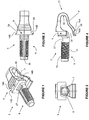
Figures 1 through 4 there is shown aclip member 3 which is part of the assembly ofline fastener 1. The clip member has amain body 6 and depending from the main body is aclipping tongue 7. The clipping tongue exists as arecurved extension 21 from themain body 6 and forms anelastic hinge 22 at or near the point of recurving. Depending outwardly from themain body 6 is a mountingportion 9 which is patterned 17 for engagement with a complimentary patterned fastener 13 (shown inFigures 8a, b and 9a, b ). However in other less preferred embodiments it may be a clip or other type fit that may be used. - The
upper presenting surface 18 of the mountingportion 9 in the preferred embodiment is flattened. There are several reasons for this. The first reason is to prevent damage to the patterned 17 engagement. A further reason is to allow a stable location for temporarily seating equipment or second member 4 (not shown) on the mountingportion 9. - On the main body also is shown a number of stop surfaces 14. The purpose of these is to locate behind 15 the
aperture 5 when engaged in the first into rack 24. This can best be seen inFigures 10 through 12 . In particular stop surface 14a locates on the surface behind 15 theaperture 5. The stop surface 14b located atfront 16 of theaperture 5 in the first member 2 or rack 24. A person skilled in the art will understand in conjunction particularly withFigures 10 through 12 , this creates an initial engagement of theclip member 3 with the surfaces infront 16 and behind 15 of theaperture 5 to substantially prevent withdrawal of theclip member 3 from theaperture 5 without further bending or hinging of theclipping tongue 7. Present also are at least one and preferably twoengagement surfaces 28 that when engaged in theaperture 5 bear on opposing regions 8 of theaperture 5. This can best be seen inFigure 12 . The result is that when theclip member 3 is located in theaperture 5, theclip member 3 is substantially held in theaperture 5,clip member 3 also and is stable and will not fall out. It is to be appreciated that theelastic hinge 22 can account for a number of different sizes and tolerances forapertures 5 and in the preferable installation is bent upwards so as to bias downward or outward with reference toFigure 4 to therefore have the engagement surfaces 28 located and urged or bias against each of its respective opposing region 8. - In the preferred embodiment of the
clip member 3, there is also present ascallop 27 opening toward the upwardly presenting as shown inFigures 1 and 4 . This scallop provides a location for thesecond member 4 orequipment 25. This provides the initial effect of preventing thesecond member 4 orequipment 25 from moving outward due to its sitting or its engagement within the scallop and thus provides some temporary security initially and also provides long term security once thefastener 13 is tightened thereon. - Present also are
side surfaces 29 as shown inFigures 1 and 3 . These have the purpose of bearing against the inner surfaces of theaperture 5 to which theclip member 3 is engaged. The person skilled in the art will understand that these surfaces together with the engagement surfaces 28 are dimensioned so as to fit the mean internal dimensions of theaperture 5. These surfaces add stability to theblind fastener 1 in its initial installation and also once tightened up using thefastener 13. The distance between stop surface 14a and stop surface 14b is dimensioned also to be substantially the same with minimal clearance as the through thickness of the first member 2 or rack 24 in which theaperture 5 is engaged. This dimensioning will provide minimal movement of theclip member 3 prior to tightening up with thefastener 13. - Seen in
Figures 1 and 4 also it can be seen the generally tapering outwardly shape from theelastic hinge 22 end of theclip member 3 toward themain body 6. Theelastic hinge 22 is the end which is inserted first into theaperture 5 and the generally tapering or expanding shape provides ease of insertion whilst also automatically loading up theclipping tongue 7 and guiding it into place on its respective opposing region 8. In the main for such insertion curved surfaces rather than sharp surfaces are present, except where there is a requirement to reduce any movement, so as to aid ease of insertion. - A
washer member 10 is shown inFigures 5a through 7b and acts as a planar bearing surface as well as a wedging component to lock theclip member 3 into theaperture 5. Thewasher member 10 presents a substantiallyplanar face 30 which can bear on the back side of thesecond member 4 orequipment 25. Present through the middle region of thewashing member 10 is awasher aperture 11. This is dimensioned so as to provide a slight or actual interference fit with the cross section dimensions of the mountingportion 9. It may for example have feathered fingers or similar and engage with thepatterning 17. This is done so as to temporarily lock thewasher member 10 in place when located on the mountingportion 9 of theclip member 3. Extending from the back side surface of thewashing member 10 is at least oneextension 12. The washer and itsextensions 12 seeks to oppose the forces on the clip member that try to extract it from theaperture 5. In the preferred embodiment there are twosuch extensions 12 as shown inFigures 7a and b. These are profiled so as to fit in thegap 31 of theclipping tongue 7 andmain body 6 as shown inFigures 4 and11 . Particularly, these extensions are tapered so as to act as wedging members when theclipping tongue 7 is elastically deformed when located in theaperture 5. The purpose of theextensions 12 will be understood whenFigure 12 is viewed. These act as a wedge or cam and bear on the lower portions of themain body 6 and the upper portions of theclipping tongue 7 to urge the two apart and therefore locate the engaging surfaces against their surfaces of theaperture 5. Furthermore the extensions lock and prevent substantial movement of theclipping tongue 7 relative to themain body 6 so at least when theblind fastener 1 is assembled with thefastener 13 in place, theblind fastener 1 cannot be extracted from theaperture 5 without substantial deformation beyond the normal scope of its use. This extends beyond the normal scope of its use and design load characteristics. - The back side surface of the
washing member 10 also hasrelief 23 so as to provide as close a fit against the front presenting surfaces of theclip member 3. This can be seen in the cross section inFigure 12 . Seen also inFigures 6a and b and 7a and b is a second relief 32 (top and bottom) that allows for a tool or a user's fingernail to prise thewashing member 10 away from theclip member 3 when installed thereon. This may be required when the two members have been engaged under force or a long period of time or under other circumstances such as the two stick or are wedged to each other. This may also be due to some partial deformation of the two, whether permanent or temporary. There may also be an interference fit between therelief 23 and those surfaces which engages with on theclip member 3 to further hold thewashing member 10 to theclip member 3. Therefore thesecond relief 32 may also be required. - A further
second relief 32 is also shown on the lower surfaces of thewasher member 10 inFigures 7a and 7b . - A preferred form of the
fastener 13 is shown inFigures 8a through 9b . In the form shown, thefastener 13 has aninternal pattern 17 that in this case is threaded to match the threading size of themount portion 9. Thefastener 13 has surface texturing 19, such as knurling present to increase the friction or contact between a user's fingers and thefastener 13 so as to allow finger tightening to as higher a degree as possible or as desired. Other surface texturing 19 different to that shown can be used and will be understood to be equivalent. Shown also is a tool profiling inFigures 9a and 8b . The purpose of this to receive a tool such as a Phillips head screwdriver or a blade screwdriver to tighten or release thefastener 13 as is needed. Thefastener 13 has a bearingsurface 33 present as shown inFigures 8a and 9b which bears up or butts up against the outer presenting surface of thesecond member 4 orequipment 25 as would be understood when viewed withFigure 12 . - Seen in
Figure 9b there is also internal profiling in addition to thepatterning 17 which allows further bearing and or stopping against the mountingportion 9. - With reference to
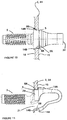
Figures 10 through 12 the assembly of the blind fastener and its use will now be described. The first member 2 or rack 24 can be seen in through section inFigures 10 and 11 . Theaperture 5 through the first member 2 or rack 24 is shown inFigure 14a and the square or rectangular profile is shown inFigure 14c . An alternative profile shown inFigure 14b is circular. It will be understood the same principals of the invention can be applied to aclip member 3 whose stop surfaces 14, engagement surfaces 28 and side surfaces 29 are contoured and profiled so as to fit such a circular arcuate orcurved aperture 5. The first member 2 has a surface behind 15 and a surface infront 16. It will be seen inFigure 10 , the stop surfaces 14b engage on the surface infront 16 and the stop surfaces 14a engage on the surfaces behind 15 as shown inFigure 11 . Also shown here is the dimensioning between the stop surfaces 14a and 14b so as to be substantially the same as the through thickness from infront 16 to behind 15 of theaperture 5 in the first member 2 (or rack 24). The method of installation is such that theelastic hinge 22 end of theclip member 3 is located first into theaperture 5 and thereafter theclip member 3 is pushed through deforming the lower portion of theclipping tongue 7 until the stop surfaces 14a and 14b engage on their respective sides of theaperture 5 and first member 2 and likewise the side surfaces 29 and engagingsurfaces 28 engage on their respective opposed regions. The opposed regions for a square orrectangular aperture 5 are shown inFigure 14c as opposing regions 8a for the engagement surfaces 28 and 8b for the side surfaces 29. In a similar way, a curved or acircular aperture 5 shown inFigure 14b will have a similar such surfaces. - With reference to
Figure 12 , there is shown the first member 2 (or rack 24) engaged as shown inFigures 10 and 11 on theclip member 3 and thereafter thewasher member 10 is slid into position over the mountingportion 9 thereafter the second member 4 (or equipment 25) is slid over the mountingportion 9 so that the mounting portion engages in the second member aperture 26 (whether fully opened or closed aperture) but under action of gravity or by the user, thesecond member 4 orequipment 25 sits down to engage thescallop 27. Thereafter thefastener 13 is engaged on the mountingportion 9 and thereafter sandwiches thesecond member 4,washer 10 andclip member 3 to assemble and hold theequipment 25 to the rack 24. - Shown in
Figure 13 is the equipment rack and specifically shown is the first member 2, which may also be the normally vertically presenting legs of the rack 24 and shown located in place is a piece ofequipment 25 and specifically thesecond member 4. Seen also are a plurality ofapertures 5 for mounting of equipment at various heights in the rack. The present invention may be supplied as a kit of parts including the equipment 25 (or second member 4) and the blind fastener consisting at least of theclip member 6 andfastener 13. Additionally there may also be supplied thewashing member 10. - Alternatively it may be the rack 24 (or first member 2) that is supplied in the kit of parts with at least one blind fastener consisting of a
clip member 3 andfastener 13 and preferably also thewashing member 10. - The foregoing description of the invention includes preferred forms thereof. Modifications may be made thereto without departing from the scope of the invention.
Claims (15)
- A blind fastener (1) adapted to engage and hold a first member (2) to a second member (4), said comprising or including,a clip member (3) adapted to install into a first aperture (5) on said first member (2), said clip member (3) having,a main body (6) and a clipping tongue (7) extending therefrom, said clipping tongue (7) biased away from said body, so that when said clipping tongue (7) and said main body (6) are located in said aperture said main body (6) and said clipping tongue (7) engage opposing regions (8) of said aperture (5), so that when engaged said clip member (3) is substantially prevented from being withdrawn from said aperture (5), and a mounting portion (9) extending outwardly from said main body (6), a washer member (10) with an aperture (11) therethrough to pass over said mounting portion (9), a fastener (13) to engage over said mounting portion (9) to secure said clip member (3), washer member (10), and said second member (4), to said first member (2), said mounting portion (9) extends through part of said second member (4), or an extension thereof, to be secured, and said fastener (13) holds said resulting assembly to secure said second member (4) to said first member (2), characterised in that said washer member (10) having at least one extension to pass between said main body (6) and said clipping tongue (7) to urge them apart and against said opposing regions (8), wherein in use said clip member (3) and washer member (10) are mounted in said aperture (11) on said first member (2).
- A blind fastener (1) as claimed in claim 1 wherein said main body (6) has at least one stop surface (14) thereon to under-engage surfaces behind and/or in front of said first aperture (5).
- A blind fastener (1) as claimed in claim 2 wherein said main body (6) has a pair of said stop surfaces (14) to under-engage in front of said aperture (5), either side of said main body (6).
- A blind fastener (1) as claimed in any one of claims 1 to 3 wherein said clipping tongue (7) also has at least one stop surface (14) to under-engage in front and/or behind said aperture (5).
- A blind fastener (1) as claimed in any one of claims 1 to 4 wherein said washer (10) has two such extensions (12) to locate substantially either side of a longitudinal axis of said clip member (3).
- A blind fastener (1) as claimed in any one of claims 1 to 5 wherein said mounting portion (9) is patterned to engage said fastener thereon.
- A blind fastener (1) as claimed in claim 6 wherein an upper presenting region of said mounting portion (9) is flattened.
- A blind fastener (1) as claimed in any one of claims 1 to 7 wherein said washer (10) is a friction fit onto said mounting portion (9).
- A blind fastener (1) as claimed in claim 8 wherein said friction fit is via said washer aperture (11).
- A blind fastener (1) as claimed in any one of claims 1 to 9 wherein said clipping tongue (7) is a re-curved extension of said main body (6) with an elastic hinge (22) between it and said main body (6) to enable said biasing.
- A blind fastener (1) as claimed in any one of claims 1 to 10 wherein said clipping tongue (7) must be elastically deformed to allow said stopping surface(s) to engage behind said aperture (11).
- A blind fastener (1) as claimed in any one of claims 1 to 11 wherein said washer (10) has a relief (23) between it and said clip member (3) to allow prising apart of said washer (10) and clip member (3) or a relief (32) on external periphery to ease its removal from said mounting portion (9).
- A blind fastener (1) as claimed in any one of claims 1 to 12 wherein said washer (10) is relieved on a side facing said clip member (3) to accommodate portions thereof in front of said first member aperture.
- A blind fastener (1) as claimed in any one of claims 1 to 13 wherein said clip member (3), at least where it traverses from in front to behind said aperture conforms to an inner periphery of said aperture (5).
- A blind fastener (1) as claimed in any one of claims 1 to 14 wherein said second member (4) sits between said washer (10) and said fastener (13).
Applications Claiming Priority (1)
| Application Number | Priority Date | Filing Date | Title |
|---|---|---|---|
| PCT/NZ2011/000230 WO2013066193A1 (en) | 2011-10-31 | 2011-10-31 | Improvements in, or relating to, fasteners |
Publications (3)
| Publication Number | Publication Date |
|---|---|
| EP2773875A1 EP2773875A1 (en) | 2014-09-10 |
| EP2773875A4 EP2773875A4 (en) | 2015-07-29 |
| EP2773875B1 true EP2773875B1 (en) | 2019-01-09 |
Family
ID=48192425
Family Applications (1)
| Application Number | Title | Priority Date | Filing Date |
|---|---|---|---|
| EP11875195.7A Active EP2773875B1 (en) | 2011-10-31 | 2011-10-31 | Improvements in or relating to fasteners |
Country Status (5)
| Country | Link |
|---|---|
| US (1) | US9523379B2 (en) |
| EP (1) | EP2773875B1 (en) |
| AU (1) | AU2011380338B2 (en) |
| NZ (1) | NZ624287A (en) |
| WO (1) | WO2013066193A1 (en) |
Families Citing this family (10)
| Publication number | Priority date | Publication date | Assignee | Title |
|---|---|---|---|---|
| CN106557128B (en) * | 2015-09-29 | 2019-09-20 | 鸿富锦精密电子(天津)有限公司 | Hard disk fixing device and fixing piece |
| JP7066618B2 (en) * | 2015-12-14 | 2022-05-13 | チャッツワース プロダクツ、インク. | How to install cage nut fasteners and cage nut fasteners without the assistance of tools |
| CN105952757A (en) * | 2016-06-27 | 2016-09-21 | 无锡迪奥机械有限公司 | Bolt with fixed binder clip |
| CN106763052A (en) * | 2016-12-16 | 2017-05-31 | 无锡市汤成机电配件厂 | Screw with clip insert body |
| US10547145B2 (en) | 2018-02-05 | 2020-01-28 | Chatworth Products, Inc. | Electric receptacle with locking feature |
| US11421720B2 (en) * | 2019-01-15 | 2022-08-23 | Whirlpool Corporation | Retention device for supporting a component and method of use |
| AU2020367697A1 (en) * | 2019-10-18 | 2022-06-09 | Rack Studs Limited | Improvements in, or relating to, fasteners |
| DE102019007332A1 (en) * | 2019-10-22 | 2021-04-22 | Maschinenfabrik Bernard Krone GmbH & Co. KG | Molded part, adjustment lock with the molded part, agricultural machine with the adjustment lock and method for assembling the adjustment lock |
| CN111395545B (en) * | 2020-04-16 | 2021-06-11 | 中国建筑第八工程局有限公司 | Wall-through pull rod |
| US11909154B1 (en) | 2021-03-08 | 2024-02-20 | Chatsworth Products, Inc. | Endcap for establishing electrical bonding connection |
Family Cites Families (26)
| Publication number | Priority date | Publication date | Assignee | Title |
|---|---|---|---|---|
| GB1123733A (en) | 1965-05-06 | 1968-08-14 | Boelkow Gmbh | Turn-bolt fastener |
| DE2626140A1 (en) * | 1976-06-11 | 1977-12-29 | Itw Ateco Gmbh | FASTENING FOR COVER PLATES |
| US4493580A (en) * | 1982-06-24 | 1985-01-15 | Illinois Tool Works, Inc. | Retaining prong |
| CA1250771A (en) | 1984-09-21 | 1989-03-07 | Roy L. Warkentin | Adjustable, anti-rotation device for a fastener receptacle |
| JPH0676804B2 (en) * | 1985-07-15 | 1994-09-28 | 株式会社ニフコ | Fasteners for fastening two panels in a face-to-face manner |
| DE4309973C2 (en) | 1993-03-26 | 1995-02-09 | Bosch Gmbh Robert | Mounting system for connecting an assembly to a subrack |
| DE9405831U1 (en) | 1994-04-07 | 1994-06-09 | Knuerr Mechanik Ag | Holding element for shelves |
| US6353542B1 (en) | 2000-01-31 | 2002-03-05 | William Craig Smith | Rack mounting bracket for mounting heavy unbalanced equipment |
| US20010046426A1 (en) * | 2000-03-27 | 2001-11-29 | Lubera Daniel J. | Resilient clip fastener |
| JP4025483B2 (en) | 2000-04-11 | 2007-12-19 | ティーオーエー株式会社 | Mounting bracket for electronic equipment casing |
| US6746193B1 (en) | 2000-11-15 | 2004-06-08 | International Business Machines Corporation | Clip assembly for use with rack-mounted equipment |
| US6594870B1 (en) * | 2001-01-22 | 2003-07-22 | Johnson Controls Technology Company | Panel fastener |
| US6538894B1 (en) | 2001-02-08 | 2003-03-25 | Unisys Corporation | Front insertion fastener system |
| DE20107949U1 (en) | 2001-05-11 | 2001-10-04 | Boellhoff Gmbh | Plug-in coupling |
| US6682282B2 (en) | 2001-09-28 | 2004-01-27 | Hewlett-Packard Development Company, L.P. | Rack mount panel fastener with interchangeable thread size |
| US6952863B2 (en) * | 2002-09-13 | 2005-10-11 | Southco, Inc. | Tether clip system |
| US7073231B2 (en) * | 2002-09-13 | 2006-07-11 | Southco, Inc. | Tether clip system |
| US7017239B2 (en) * | 2002-12-17 | 2006-03-28 | Illinois Tool Works Inc. | Component connection system |
| US6955512B2 (en) | 2003-07-21 | 2005-10-18 | Hewlett-Packard Development Company, L.P. | Mounting device for securing an electronic device to an equipment rack |
| EP1555866A3 (en) | 2004-01-16 | 2009-02-25 | Pentair Electronic Packaging Co. | Universal connector for mounting a telescoping slide rail assembly in a rack |
| US20070145220A1 (en) | 2005-12-28 | 2007-06-28 | International Business Machines Corporation | Mountings for rack mounted device |
| JP4757659B2 (en) | 2006-02-23 | 2011-08-24 | 三菱電機株式会社 | tightening structure |
| US7731142B2 (en) | 2007-12-28 | 2010-06-08 | King Slide Works Co., Ltd. | Tool-less mounting slide bracket |
| EP2099273A1 (en) | 2008-03-03 | 2009-09-09 | Schroff GmbH | Electronic assembly for transport in an assembly carrier |
| JP4444357B1 (en) | 2008-11-20 | 2010-03-31 | 株式会社東芝 | Tightening and fixing device, module mounting structure and information processing device |
| US8769779B2 (en) * | 2011-03-24 | 2014-07-08 | Ford Global Technologies, Llc | Inertia locking hidden pushpin |
-
2011
- 2011-10-31 EP EP11875195.7A patent/EP2773875B1/en active Active
- 2011-10-31 US US14/355,122 patent/US9523379B2/en active Active
- 2011-10-31 WO PCT/NZ2011/000230 patent/WO2013066193A1/en active Application Filing
- 2011-10-31 AU AU2011380338A patent/AU2011380338B2/en active Active
- 2011-10-31 NZ NZ624287A patent/NZ624287A/en unknown
Non-Patent Citations (1)
| Title |
|---|
| None * |
Also Published As
| Publication number | Publication date |
|---|---|
| EP2773875A1 (en) | 2014-09-10 |
| NZ624287A (en) | 2016-12-23 |
| EP2773875A4 (en) | 2015-07-29 |
| WO2013066193A1 (en) | 2013-05-10 |
| US20140366335A1 (en) | 2014-12-18 |
| AU2011380338A1 (en) | 2014-05-22 |
| US9523379B2 (en) | 2016-12-20 |
| AU2011380338B2 (en) | 2017-04-20 |
Similar Documents
| Publication | Publication Date | Title |
|---|---|---|
| EP2773875B1 (en) | Improvements in or relating to fasteners | |
| US4802716A (en) | Fitting assembly for connecting the sidewall of a drawer to the rear wall thereof | |
| US9033294B2 (en) | Release preventing system for wall cupboards | |
| CA2061981C (en) | Self-aligning fastener system | |
| US8162559B2 (en) | Connector for panels or panel-like components | |
| US20070159039A1 (en) | Drawer assembly | |
| CA3000959A1 (en) | Hook rail | |
| US7338241B2 (en) | Fastener receptacle | |
| US20060099049A1 (en) | Fastener/stud retainer | |
| US20090080999A1 (en) | Toolless mechanical fastener | |
| WO2007135510A1 (en) | A connector for panels or panel-like components | |
| KR100786183B1 (en) | Rail and supports therefor | |
| EP0971572A1 (en) | An assembly comprising two components and a mechanism for fastening them together | |
| US20010031190A1 (en) | Rectangular hole snap-in fastener | |
| US6079081A (en) | Door mount assembly for storage rack | |
| CA2810174C (en) | Corner insert for sheet panel assembly | |
| US6865774B2 (en) | Caster device | |
| US8448325B2 (en) | Drawer dishwasher installation kit assembly | |
| US20230349198A1 (en) | Anti-theft perforated wall board lock | |
| US20220412388A1 (en) | Improvements In, Or Relating To, Fasteners | |
| US20050132537A1 (en) | Drawer pull | |
| CN220810681U (en) | Vertical warehouse back net fixing piece | |
| EP3773072B1 (en) | Hook member for modular furniture | |
| JP3094111U (en) | Fixtures for hanging shelves | |
| JPH0928589A (en) | Front plate mounting structure of washstand |
Legal Events
| Date | Code | Title | Description |
|---|---|---|---|
| PUAI | Public reference made under article 153(3) epc to a published international application that has entered the european phase |
Free format text: ORIGINAL CODE: 0009012 |
|
| 17P | Request for examination filed |
Effective date: 20140528 |
|
| AK | Designated contracting states |
Kind code of ref document: A1 Designated state(s): AL AT BE BG CH CY CZ DE DK EE ES FI FR GB GR HR HU IE IS IT LI LT LU LV MC MK MT NL NO PL PT RO RS SE SI SK SM TR |
|
| DAX | Request for extension of the european patent (deleted) | ||
| RA4 | Supplementary search report drawn up and despatched (corrected) |
Effective date: 20150629 |
|
| RIC1 | Information provided on ipc code assigned before grant |
Ipc: F16B 5/06 20060101ALI20150623BHEP Ipc: F16B 13/04 20060101AFI20150623BHEP |
|
| 17Q | First examination report despatched |
Effective date: 20160630 |
|
| STAA | Information on the status of an ep patent application or granted ep patent |
Free format text: STATUS: EXAMINATION IS IN PROGRESS |
|
| RAP3 | Party data changed (applicant data changed or rights of an application transferred) |
Owner name: RACK STUDS LIMITED |
|
| GRAP | Despatch of communication of intention to grant a patent |
Free format text: ORIGINAL CODE: EPIDOSNIGR1 |
|
| STAA | Information on the status of an ep patent application or granted ep patent |
Free format text: STATUS: GRANT OF PATENT IS INTENDED |
|
| INTG | Intention to grant announced |
Effective date: 20180406 |
|
| GRAS | Grant fee paid |
Free format text: ORIGINAL CODE: EPIDOSNIGR3 |
|
| GRAA | (expected) grant |
Free format text: ORIGINAL CODE: 0009210 |
|
| STAA | Information on the status of an ep patent application or granted ep patent |
Free format text: STATUS: THE PATENT HAS BEEN GRANTED |
|
| AK | Designated contracting states |
Kind code of ref document: B1 Designated state(s): AL AT BE BG CH CY CZ DE DK EE ES FI FR GB GR HR HU IE IS IT LI LT LU LV MC MK MT NL NO PL PT RO RS SE SI SK SM TR |
|
| REG | Reference to a national code |
Ref country code: GB Ref legal event code: FG4D |
|
| REG | Reference to a national code |
Ref country code: CH Ref legal event code: EP Ref country code: AT Ref legal event code: REF Ref document number: 1087669 Country of ref document: AT Kind code of ref document: T Effective date: 20190115 |
|
| REG | Reference to a national code |
Ref country code: DE Ref legal event code: R096 Ref document number: 602011055677 Country of ref document: DE |
|
| REG | Reference to a national code |
Ref country code: IE Ref legal event code: FG4D |
|
| REG | Reference to a national code |
Ref country code: NL Ref legal event code: FP |
|
| REG | Reference to a national code |
Ref country code: LT Ref legal event code: MG4D |
|
| REG | Reference to a national code |
Ref country code: AT Ref legal event code: MK05 Ref document number: 1087669 Country of ref document: AT Kind code of ref document: T Effective date: 20190109 |
|
| PG25 | Lapsed in a contracting state [announced via postgrant information from national office to epo] |
Ref country code: PL Free format text: LAPSE BECAUSE OF FAILURE TO SUBMIT A TRANSLATION OF THE DESCRIPTION OR TO PAY THE FEE WITHIN THE PRESCRIBED TIME-LIMIT Effective date: 20190109 Ref country code: SE Free format text: LAPSE BECAUSE OF FAILURE TO SUBMIT A TRANSLATION OF THE DESCRIPTION OR TO PAY THE FEE WITHIN THE PRESCRIBED TIME-LIMIT Effective date: 20190109 Ref country code: ES Free format text: LAPSE BECAUSE OF FAILURE TO SUBMIT A TRANSLATION OF THE DESCRIPTION OR TO PAY THE FEE WITHIN THE PRESCRIBED TIME-LIMIT Effective date: 20190109 Ref country code: LT Free format text: LAPSE BECAUSE OF FAILURE TO SUBMIT A TRANSLATION OF THE DESCRIPTION OR TO PAY THE FEE WITHIN THE PRESCRIBED TIME-LIMIT Effective date: 20190109 Ref country code: NO Free format text: LAPSE BECAUSE OF FAILURE TO SUBMIT A TRANSLATION OF THE DESCRIPTION OR TO PAY THE FEE WITHIN THE PRESCRIBED TIME-LIMIT Effective date: 20190409 Ref country code: PT Free format text: LAPSE BECAUSE OF FAILURE TO SUBMIT A TRANSLATION OF THE DESCRIPTION OR TO PAY THE FEE WITHIN THE PRESCRIBED TIME-LIMIT Effective date: 20190509 Ref country code: FI Free format text: LAPSE BECAUSE OF FAILURE TO SUBMIT A TRANSLATION OF THE DESCRIPTION OR TO PAY THE FEE WITHIN THE PRESCRIBED TIME-LIMIT Effective date: 20190109 |
|
| PG25 | Lapsed in a contracting state [announced via postgrant information from national office to epo] |
Ref country code: GR Free format text: LAPSE BECAUSE OF FAILURE TO SUBMIT A TRANSLATION OF THE DESCRIPTION OR TO PAY THE FEE WITHIN THE PRESCRIBED TIME-LIMIT Effective date: 20190410 Ref country code: IS Free format text: LAPSE BECAUSE OF FAILURE TO SUBMIT A TRANSLATION OF THE DESCRIPTION OR TO PAY THE FEE WITHIN THE PRESCRIBED TIME-LIMIT Effective date: 20190509 Ref country code: RS Free format text: LAPSE BECAUSE OF FAILURE TO SUBMIT A TRANSLATION OF THE DESCRIPTION OR TO PAY THE FEE WITHIN THE PRESCRIBED TIME-LIMIT Effective date: 20190109 Ref country code: BG Free format text: LAPSE BECAUSE OF FAILURE TO SUBMIT A TRANSLATION OF THE DESCRIPTION OR TO PAY THE FEE WITHIN THE PRESCRIBED TIME-LIMIT Effective date: 20190409 Ref country code: HR Free format text: LAPSE BECAUSE OF FAILURE TO SUBMIT A TRANSLATION OF THE DESCRIPTION OR TO PAY THE FEE WITHIN THE PRESCRIBED TIME-LIMIT Effective date: 20190109 Ref country code: LV Free format text: LAPSE BECAUSE OF FAILURE TO SUBMIT A TRANSLATION OF THE DESCRIPTION OR TO PAY THE FEE WITHIN THE PRESCRIBED TIME-LIMIT Effective date: 20190109 |
|
| REG | Reference to a national code |
Ref country code: DE Ref legal event code: R097 Ref document number: 602011055677 Country of ref document: DE |
|
| PG25 | Lapsed in a contracting state [announced via postgrant information from national office to epo] |
Ref country code: AL Free format text: LAPSE BECAUSE OF FAILURE TO SUBMIT A TRANSLATION OF THE DESCRIPTION OR TO PAY THE FEE WITHIN THE PRESCRIBED TIME-LIMIT Effective date: 20190109 Ref country code: SK Free format text: LAPSE BECAUSE OF FAILURE TO SUBMIT A TRANSLATION OF THE DESCRIPTION OR TO PAY THE FEE WITHIN THE PRESCRIBED TIME-LIMIT Effective date: 20190109 Ref country code: EE Free format text: LAPSE BECAUSE OF FAILURE TO SUBMIT A TRANSLATION OF THE DESCRIPTION OR TO PAY THE FEE WITHIN THE PRESCRIBED TIME-LIMIT Effective date: 20190109 Ref country code: DK Free format text: LAPSE BECAUSE OF FAILURE TO SUBMIT A TRANSLATION OF THE DESCRIPTION OR TO PAY THE FEE WITHIN THE PRESCRIBED TIME-LIMIT Effective date: 20190109 Ref country code: AT Free format text: LAPSE BECAUSE OF FAILURE TO SUBMIT A TRANSLATION OF THE DESCRIPTION OR TO PAY THE FEE WITHIN THE PRESCRIBED TIME-LIMIT Effective date: 20190109 Ref country code: RO Free format text: LAPSE BECAUSE OF FAILURE TO SUBMIT A TRANSLATION OF THE DESCRIPTION OR TO PAY THE FEE WITHIN THE PRESCRIBED TIME-LIMIT Effective date: 20190109 Ref country code: IT Free format text: LAPSE BECAUSE OF FAILURE TO SUBMIT A TRANSLATION OF THE DESCRIPTION OR TO PAY THE FEE WITHIN THE PRESCRIBED TIME-LIMIT Effective date: 20190109 Ref country code: CZ Free format text: LAPSE BECAUSE OF FAILURE TO SUBMIT A TRANSLATION OF THE DESCRIPTION OR TO PAY THE FEE WITHIN THE PRESCRIBED TIME-LIMIT Effective date: 20190109 |
|
| PLBE | No opposition filed within time limit |
Free format text: ORIGINAL CODE: 0009261 |
|
| STAA | Information on the status of an ep patent application or granted ep patent |
Free format text: STATUS: NO OPPOSITION FILED WITHIN TIME LIMIT |
|
| PG25 | Lapsed in a contracting state [announced via postgrant information from national office to epo] |
Ref country code: SM Free format text: LAPSE BECAUSE OF FAILURE TO SUBMIT A TRANSLATION OF THE DESCRIPTION OR TO PAY THE FEE WITHIN THE PRESCRIBED TIME-LIMIT Effective date: 20190109 |
|
| 26N | No opposition filed |
Effective date: 20191010 |
|
| PG25 | Lapsed in a contracting state [announced via postgrant information from national office to epo] |
Ref country code: SI Free format text: LAPSE BECAUSE OF FAILURE TO SUBMIT A TRANSLATION OF THE DESCRIPTION OR TO PAY THE FEE WITHIN THE PRESCRIBED TIME-LIMIT Effective date: 20190109 |
|
| PG25 | Lapsed in a contracting state [announced via postgrant information from national office to epo] |
Ref country code: TR Free format text: LAPSE BECAUSE OF FAILURE TO SUBMIT A TRANSLATION OF THE DESCRIPTION OR TO PAY THE FEE WITHIN THE PRESCRIBED TIME-LIMIT Effective date: 20190109 |
|
| PG25 | Lapsed in a contracting state [announced via postgrant information from national office to epo] |
Ref country code: MC Free format text: LAPSE BECAUSE OF FAILURE TO SUBMIT A TRANSLATION OF THE DESCRIPTION OR TO PAY THE FEE WITHIN THE PRESCRIBED TIME-LIMIT Effective date: 20190109 |
|
| REG | Reference to a national code |
Ref country code: CH Ref legal event code: PL |
|
| PG25 | Lapsed in a contracting state [announced via postgrant information from national office to epo] |
Ref country code: LI Free format text: LAPSE BECAUSE OF NON-PAYMENT OF DUE FEES Effective date: 20191031 Ref country code: CH Free format text: LAPSE BECAUSE OF NON-PAYMENT OF DUE FEES Effective date: 20191031 Ref country code: LU Free format text: LAPSE BECAUSE OF NON-PAYMENT OF DUE FEES Effective date: 20191031 |
|
| REG | Reference to a national code |
Ref country code: BE Ref legal event code: MM Effective date: 20191031 |
|
| PG25 | Lapsed in a contracting state [announced via postgrant information from national office to epo] |
Ref country code: BE Free format text: LAPSE BECAUSE OF NON-PAYMENT OF DUE FEES Effective date: 20191031 |
|
| PG25 | Lapsed in a contracting state [announced via postgrant information from national office to epo] |
Ref country code: CY Free format text: LAPSE BECAUSE OF FAILURE TO SUBMIT A TRANSLATION OF THE DESCRIPTION OR TO PAY THE FEE WITHIN THE PRESCRIBED TIME-LIMIT Effective date: 20190109 |
|
| PG25 | Lapsed in a contracting state [announced via postgrant information from national office to epo] |
Ref country code: HU Free format text: LAPSE BECAUSE OF FAILURE TO SUBMIT A TRANSLATION OF THE DESCRIPTION OR TO PAY THE FEE WITHIN THE PRESCRIBED TIME-LIMIT; INVALID AB INITIO Effective date: 20111031 Ref country code: MT Free format text: LAPSE BECAUSE OF FAILURE TO SUBMIT A TRANSLATION OF THE DESCRIPTION OR TO PAY THE FEE WITHIN THE PRESCRIBED TIME-LIMIT Effective date: 20190109 |
|
| PG25 | Lapsed in a contracting state [announced via postgrant information from national office to epo] |
Ref country code: MK Free format text: LAPSE BECAUSE OF FAILURE TO SUBMIT A TRANSLATION OF THE DESCRIPTION OR TO PAY THE FEE WITHIN THE PRESCRIBED TIME-LIMIT Effective date: 20190109 |
|
| PGFP | Annual fee paid to national office [announced via postgrant information from national office to epo] |
Ref country code: NL Payment date: 20231012 Year of fee payment: 13 |
|
| PGFP | Annual fee paid to national office [announced via postgrant information from national office to epo] |
Ref country code: GB Payment date: 20231009 Year of fee payment: 13 |
|
| PGFP | Annual fee paid to national office [announced via postgrant information from national office to epo] |
Ref country code: IE Payment date: 20231009 Year of fee payment: 13 Ref country code: FR Payment date: 20231009 Year of fee payment: 13 Ref country code: DE Payment date: 20231030 Year of fee payment: 13 |