EP2773252B1 - Vacuum cleaner nozzle - Google Patents
Vacuum cleaner nozzle Download PDFInfo
- Publication number
- EP2773252B1 EP2773252B1 EP13794937.6A EP13794937A EP2773252B1 EP 2773252 B1 EP2773252 B1 EP 2773252B1 EP 13794937 A EP13794937 A EP 13794937A EP 2773252 B1 EP2773252 B1 EP 2773252B1
- Authority
- EP
- European Patent Office
- Prior art keywords
- wheel
- nozzle
- suction
- axis
- suction pipe
- Prior art date
- Legal status (The legal status is an assumption and is not a legal conclusion. Google has not performed a legal analysis and makes no representation as to the accuracy of the status listed.)
- Revoked
Links
- 239000000428 dust Substances 0.000 description 8
- 238000011086 high cleaning Methods 0.000 description 2
- 230000001788 irregular Effects 0.000 description 2
- 238000004140 cleaning Methods 0.000 description 1
- 230000001419 dependent effect Effects 0.000 description 1
- 238000005259 measurement Methods 0.000 description 1
- 230000004044 response Effects 0.000 description 1
Images

Classifications
-
- A—HUMAN NECESSITIES
- A47—FURNITURE; DOMESTIC ARTICLES OR APPLIANCES; COFFEE MILLS; SPICE MILLS; SUCTION CLEANERS IN GENERAL
- A47L—DOMESTIC WASHING OR CLEANING; SUCTION CLEANERS IN GENERAL
- A47L9/00—Details or accessories of suction cleaners, e.g. mechanical means for controlling the suction or for effecting pulsating action; Storing devices specially adapted to suction cleaners or parts thereof; Carrying-vehicles specially adapted for suction cleaners
- A47L9/02—Nozzles
Definitions
- the present invention relates to a nozzle for a vacuum cleaner, and to a vacuum cleaner having such a nozzle.
- EP1875846 and WO 2007/031819 disclose prior art nozzles for floor vacuum cleaners.
- a good vacuum cleaner nozzle must have high cleaning performance, i.e. effective debris pick up, but at the same time be easy to handle and move across a surface to be cleaned, such as a carpet.
- high cleaning performance is obtained only at the expense of an increased resistance to motion across a surface and so requires an increased application of force by the user to move the nozzle.
- the nozzle may have unpleasant dynamic behaviour in the sense that it does not move particularly well across a surface when it is pushed and/or pulled.
- a nozzle for a vacuum cleaner comprising a soleplate with a suction channel slot therein for the suction of debris from a surface, a wheel mounted for rotation about an axis to support the nozzle on said surface, and a suction pipe connector for rotation about an axis that is coaxial with said wheel axis, the wheel having a radius (h) of at least 25mm, and wherein a distance (X) across the surface between a point of contact of the wheel with the surface that is directly beneath the wheel axis and a point midway between the leading and trailing edges of the suction channel slot is no greater than 80mm
- the nozzle comprises a housing in which the soleplate and suction channel slot are formed, and the wheel and suction pipe connector may be mounted to the housing for rotation about said wheel axis.
- the nozzle may comprise a housing in which the soleplate and suction channel slot are formed, the wheel and suction pipe connector being mounted for rotation relative to each other about the wheel axis, and the housing being mounted for rotation relative to the wheel and the suction pipe connector about a second axis parallel to and spaced from the first axis.
- a link arm extends between said wheel axis and the second axis, and is pivotally connected to each of the suction pipe connector and the housing.
- the ratio of the radius of the wheel (h) to the sum of the distance X across the surface between a point of contact of the wheel with the surface that is directly beneath the wheel axis and a point midway between the leading and trailing edges of the suction channel slot and a distance (1/2 C) across the surface between the point midway between the leading and trailing edges of the suction channel slot and the leading edge of the suction channel slot is greater than 0.3.
- a vacuum cleaner including a suction pipe and a nozzle according to the invention, the suction pipe being connected to the nozzle via the suction pipe connector.
- FIG. 1 A cross-sectional side elevation of a conventional nozzle 1 for a vacuum cleaner (not shown) is illustrated in Figures 1 and 2 .
- the nozzle 1 comprises a main body or housing 2 having an elbow or suction pipe connector 3 attached to a rear end of the housing 2 for rotation relative to the housing 2 about an axis A.
- a suction pipe 4, which does not form part of the nozzle 1, is attachable to and extends upwardly from the suction pipe connector 3.
- the suction pipe 4 provides a conduit for the passage of dust and debris that has been sucked from a surface S and having been vacuumed through the nozzle 1.
- the suction pipe 4 also acts as a handle to enable a user to push the nozzle in a forward F direction and pull it in a rearward R direction during use.
- a wheel 5 is mounted to the housing 2. It is also mounted to the suction pipe connector 3 for rotation about the same axis A as the suction pipe connector 3 to support and guide the nozzle 1 across the surface S.
- the underside of the housing 2 is provided with a soleplate 6 which contacts the surface S being vacuumed.
- An elongate suction channel slot 7 is formed in the soleplate 6 and extends across the width of the housing 2 substantially at right angles to the forward F and rearward R directions of movement.
- the elongate suction channel slot 7 has parallel leading and trailing edges 7a, 7b that define the edges of the slot 7 in the soleplate 6. It will also be appreciated that the slot 7 may have a different shape.
- Thread or debris pick-up strips 8 may be provided forwardly of the leading edge 7a and/or rearwardly of the trailing edge 7b to assist in releasing hair or threads from the surface S being vacuumed.
- the main phenomenon behind dust pickup from a surface S such as a carpet is the opening of the pile.
- a vertical force has to be applied on the leading edge 7a of the suction slot 7.
- the only force that is generated in this direction apart from the force generated as a result of the weight of the nozzle 1 itself, is a horizontal friction force that is applied by the user via the suction pipe 4 to push the nozzle 1 across the carpet surface S.
- distance h is important.
- Distance h is the distance from the axis of rotation A of the wheel 5 to the surface S, and is equivalent to the radius of the wheel 5. As distance h increases, the higher the downward vertical force V of the suction edge against the pile will be as the vacuum cleaner is pushed in the forward direction F along the surface S by a user who applies a force to the nozzle 1 via the suction pipe 4 in a direction that extends along line P.
- distance q represents the length of a line that extends from the leading edge 7a of the suction slot 7 and intersects at right-angles with the line P along which the force F is applied to the nozzle 1 which is generated by a user as a result of pulling the suction pipe 4 across the carpet surface S.
- a moment/torque T is generated (as indicated by arrow T in Figure 2 ) that causes the nozzle to pivot on the carpet surface S about the leading edge 7a of the suction slot 7 that results in the nozzle 1 tilting and the wheel 5 lifting off the ground (as shown by dotted lines indicated as 5a in Figure 2 ) until the torque T is at zero, which occurs when the the leading edge 7a and the wheel axis A both lie on the same line as the applied force P.
- this tilting action is undesirable because the trailing edge 7b of the suction slot 7 is no longer in contact with the carpet surface S, and so air will start seeping in through a bypass path, rather than through the carpet, and so this is undesirable and results in a reduction in suction performance.
- the tilting action also causes unpleasant bouncing, irregular movements of the nozzle 1.
- the distance q should be maintained as small as possible in order to minimise the undesirable tilting action explained in more detail above.
- the distance h needs to be selected so as to maintain a vertical force V which will maintain the suction slot 7 against the pile when the nozzle 1 is pushed in a forward direction F.
- the inventors have determined that to balance the requirement of preventing loss of suction when the nozzle 1 is pushed in the forward direction F, and the requirement to minimise or alleviate bouncing and irregular movement of the nozzle 1 (by maintaining a low distance q and keeping the aforementioned torque T at a minimum) when the nozzle 1 is pulled in the rearward direction R, a certain combination of wheel diameter h and the distance of the wheel to the centre of the suction channel 7 is important. By selecting these parameters carefully, it has been found that a good balance between effective dust pick up and the force required by a user to move the nozzle 1 easity when it is pushed in the forward F direction and also when it is being pulled in the rearward direction R is achieved.
- the dimension q should be smaller than 24 mm to provide the best possible performance of the nozzle 1 when it is being pulled in the rearward direction R.
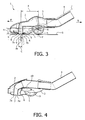
- the distance q is related to the distance of the wheel axle A above the surface S (i.e. dimension h referred to above, which is equivalent to the radius of the wheel 5), and the dimension X (see Figure 3 ), which is the distance across the surface S between the point of contact Y of the wheel 5 with the surface S directly below the axis A, and a centre line M (see Figure 3 ) midway between the leading and trailing edges 7a, 7b of the suction channel slot 7, i.e. an imaginary centre line that is parallel to and equidistant from both the leading and the trailing edges 7a, 7b of the suction channel slot 7.
- the centre line M is positioned at 1/2C from the leading and trailing edges 7a, 7b.
- the suction channel slot 7 is ideally rectangular in shape, and extends across the width of the nozzle 1 in a direction at right angles to the forward F and backward R direction of movement of the nozzle 1, and parallel to the wheel axis A.
- the suction channel slot may be shaped or extend at an angle in some way, in which case the measurement X referred to above should be taken from at a central point, midway between each end of the slot 7 in a direction across the width of the nozzle 1.
- this formula is derived assuming the suction slot width C as 20mm.
- the slot width C is in the region of 18 to 21mm.
- the ratio is less than 0.3, the force required to push the nozzle in the forward direction F is smaller, as would be the vertical force V acting on the leading edge 7a of the nozzle 1. Consequently, the dust pickup efficiency would reduce.
- a ratio of less than 0.3 results in a larger value for distance q, and so the torque required to cause the nozzle 1 to tilt increases when the nozzle 1 is being pulled in the rearward direction R.
- the specified parameters are chosen so as to provide a ratio of greater than 0.3, the vertical force V on the leading edge 7a of the nozzle 1 for a given force applied by the user to push the nozzle 1 forward is higher than whenever parameters are chosen which are smaller then the specified ratio.
- distance q will be resulting in less torque T on the nozzle for the same friction force than whenever a setting is chosen outside the specified ratio.
- the nozzle 1 for a vacuum cleaner comprising the housing 2 having the soleplate 6 with the suction channel slot 7 therein for the suction of debris from the surface S, the wheel 5 mounted to the housing 2 for rotation about the axis 1 that extends substantially parallel to the leading and trailing edges 7a, 7b of said suction channel slot 7 to support the nozzle 1 on said surface S, and the suction pipe connector 3 mounted to the housing 2 for rotation about an axis that is coaxial with said wheel axis A.
- the ratio of the radius h of the wheel 5 to the distance X across a surface, between the point of contact Y of the wheel 5 with the surface S that is directly beneath the wheel axis 1, and the point midway between the leading and trailing edges 7a, 7b of the suction channel slot 7 is greater than 0.3.
- the parameters are selected so as to provide a ratio of greater than 0.3 when the width C of the suction slot 7 lies in the range of 18 to 21mm.
- FIG 4 The embodiment shown in Figure 4 is the same as that shown in Figure 3 , except that the wheel 5 is pivotally mounted to the suction pipe connector 3, d the housing 2 is pivotally mounted to the suction pipe connector 3 for rotation about a second axis B which is spaced from the wheel axis A.
- a link arm 10 extends between the axes A and B, and connects the housing 2 to the suction pipe connector 3. It will be appreciated that, in this embodiment, the housing 2 can pivot about axis B independently to movement of the suction pipe connector 3 and the wheel 5 about axis A, and so the housing 2 can assume a different angle during the forward F and backward R strokes.
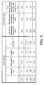
- Figure 5 is a table that provides a number of ratios obtained from the equation identified above with different vacuum cleaner nozzles 1 having differing values for distance X, wheel radius h and slot width C. It also demonstrates how dust pick up efficiency and motion resistance is optimised when the calculated ratio is greater than 0.3 "Nozzle 1" represents the nozzle according to the invention, whereas "nozzles 2, 3 and 4" represent those of the prior art. Although this table represents values obtained from a nozzle 1 having a double hinge arrangement, as described with reference to Figure 4 , similar advantages are obtained with the nozzle 1 described with reference to Figure 3 in which there is only one pivot point.
Landscapes
- Engineering & Computer Science (AREA)
- Mechanical Engineering (AREA)
- Nozzles For Electric Vacuum Cleaners (AREA)
Description
- The present invention relates to a nozzle for a vacuum cleaner, and to a vacuum cleaner having such a nozzle.
-
EP1875846 andWO 2007/031819 disclose prior art nozzles for floor vacuum cleaners. - A good vacuum cleaner nozzle must have high cleaning performance, i.e. effective debris pick up, but at the same time be easy to handle and move across a surface to be cleaned, such as a carpet. In many conventional nozzles, high cleaning performance is obtained only at the expense of an increased resistance to motion across a surface and so requires an increased application of force by the user to move the nozzle. Furthermore, the nozzle may have unpleasant dynamic behaviour in the sense that it does not move particularly well across a surface when it is pushed and/or pulled. These disadvantages can make the vacuum cleaner difficult and tiring to use for prolonged periods.
- It is an object of this invention to overcome or substantially alleviate the problems referred to above, and to provide a nozzle for a vacuum cleaner that combines optimum cleaning performance with minimal motion resistance and more desirable dynamic behaviour.
- According to the present invention, there is provided a nozzle for a vacuum cleaner, comprising a soleplate with a suction channel slot therein for the suction of debris from a surface, a wheel mounted for rotation about an axis to support the nozzle on said surface, and a suction pipe connector for rotation about an axis that is coaxial with said wheel axis, the wheel having a radius (h) of at least 25mm, and wherein a distance (X) across the surface between a point of contact of the wheel with the surface that is directly beneath the wheel axis and a point midway between the leading and trailing edges of the suction channel slot is no greater than 80mm
- In one embodiment, the nozzle comprises a housing in which the soleplate and suction channel slot are formed, and the wheel and suction pipe connector may be mounted to the housing for rotation about said wheel axis.
- In another embodiment, the nozzle may comprise a housing in which the soleplate and suction channel slot are formed, the wheel and suction pipe connector being mounted for rotation relative to each other about the wheel axis, and the housing being mounted for rotation relative to the wheel and the suction pipe connector about a second axis parallel to and spaced from the first axis.
- Preferably, a link arm extends between said wheel axis and the second axis, and is pivotally connected to each of the suction pipe connector and the housing.
- In a preferred embodiment, the ratio of the radius of the wheel (h) to the sum of the distance X across the surface between a point of contact of the wheel with the surface that is directly beneath the wheel axis and a point midway between the leading and trailing edges of the suction channel slot and a distance (1/2 C) across the surface between the point midway between the leading and trailing edges of the suction channel slot and the leading edge of the suction channel slot is greater than 0.3.
- According to the invention, there is also provided a vacuum cleaner including a suction pipe and a nozzle according to the invention, the suction pipe being connected to the nozzle via the suction pipe connector.
- Embodiments of the invention will now be described, by way of example only, with reference to the accompanying drawings, in which:
-
Figure 1 illustrates a side cross-sectional elevation of a conventional vacuum cleaner nozzle; -
Figure 2 illustrates the same side cross-sectional elevation as shown inFigure 1 , but annotated to show torque T and movement of the wheel caused by wheel lift; and -
Figure 3 illustrates a side cross-sectional elevation of a vacuum cleaner nozzle according to the present invention; -
Figure 4 illustrates a side cross-sectional elevation of a nozzle according to another embodiment of the invention, in which the nozzle has a housing that is mounted for rotation about an axis that is spaced from the axis of rotation of the wheel axis; and -
Figure 5 is a table to illustrate the performance of a nozzle having a ratio of greater than 0.3 compared to the performance of some conventional nozzles. - A cross-sectional side elevation of a
conventional nozzle 1 for a vacuum cleaner (not shown) is illustrated inFigures 1 and 2 . Thenozzle 1 comprises a main body orhousing 2 having an elbow orsuction pipe connector 3 attached to a rear end of thehousing 2 for rotation relative to thehousing 2 about an axis A. Asuction pipe 4, which does not form part of thenozzle 1, is attachable to and extends upwardly from thesuction pipe connector 3. Thesuction pipe 4 provides a conduit for the passage of dust and debris that has been sucked from a surface S and having been vacuumed through thenozzle 1. Thesuction pipe 4 also acts as a handle to enable a user to push the nozzle in a forward F direction and pull it in a rearward R direction during use. - In the first embodiment, a
wheel 5 is mounted to thehousing 2. It is also mounted to thesuction pipe connector 3 for rotation about the same axis A as thesuction pipe connector 3 to support and guide thenozzle 1 across the surface S. - The underside of the
housing 2 is provided with asoleplate 6 which contacts the surface S being vacuumed. An elongatesuction channel slot 7 is formed in thesoleplate 6 and extends across the width of thehousing 2 substantially at right angles to the forward F and rearward R directions of movement. The elongatesuction channel slot 7 has parallel leading andtrailing edges slot 7 in thesoleplate 6. It will also be appreciated that theslot 7 may have a different shape. - Thread or debris pick-
up strips 8 may be provided forwardly of the leadingedge 7a and/or rearwardly of thetrailing edge 7b to assist in releasing hair or threads from the surface S being vacuumed. - To achieve high dust pickup levels, it is necessary to maintain the
suction channel slot 7 in contact with the surface S, i.e. the leading andtrailing edges suction slot 7, the wheel axis A and the direction in which force is applied to thehousing 2 via thesuction pipe 4 andsuction pipe connector 3 are all important factors, as they determine the behavior and the forces acting on thenozzle 1. - The main phenomenon behind dust pickup from a surface S such as a carpet is the opening of the pile. To be able to open the pile during movement of the
nozzle 1 in a forward direction F, a vertical force has to be applied on the leadingedge 7a of thesuction slot 7. However the only force that is generated in this direction, apart from the force generated as a result of the weight of thenozzle 1 itself, is a horizontal friction force that is applied by the user via thesuction pipe 4 to push thenozzle 1 across the carpet surface S. To transform this frictional force into a vertical force V on the leadingedge 7a to open the pile, distance h (seeFigure 2 ) is important. Distance h is the distance from the axis of rotation A of thewheel 5 to the surface S, and is equivalent to the radius of thewheel 5. As distance h increases, the higher the downward vertical force V of the suction edge against the pile will be as the vacuum cleaner is pushed in the forward direction F along the surface S by a user who applies a force to thenozzle 1 via thesuction pipe 4 in a direction that extends along line P. - However, in the rearward stroke R of the
nozzle 1, distance q (seeFigure 2 ) is important. Distance q represents the length of a line that extends from the leadingedge 7a of thesuction slot 7 and intersects at right-angles with the line P along which the force F is applied to thenozzle 1 which is generated by a user as a result of pulling thesuction pipe 4 across the carpet surface S. - When the user pulls the
nozzle 1 rearwardly R, there is a tendency for the distance q to approach zero, i.e. a moment/torque T is generated (as indicated by arrow T inFigure 2 ) that causes the nozzle to pivot on the carpet surface S about the leadingedge 7a of thesuction slot 7 that results in thenozzle 1 tilting and thewheel 5 lifting off the ground (as shown by dotted lines indicated as 5a inFigure 2 ) until the torque T is at zero, which occurs when the the leadingedge 7a and the wheel axis A both lie on the same line as the applied force P. For attaining high dust pickup levels this tilting action is undesirable because thetrailing edge 7b of thesuction slot 7 is no longer in contact with the carpet surface S, and so air will start seeping in through a bypass path, rather than through the carpet, and so this is undesirable and results in a reduction in suction performance. The tilting action also causes unpleasant bouncing, irregular movements of thenozzle 1. - Ideally, the distance q should be maintained as small as possible in order to minimise the undesirable tilting action explained in more detail above. At the same time, the distance h needs to be selected so as to maintain a vertical force V which will maintain the
suction slot 7 against the pile when thenozzle 1 is pushed in a forward direction F. - The inventors have determined that to balance the requirement of preventing loss of suction when the
nozzle 1 is pushed in the forward direction F, and the requirement to minimise or alleviate bouncing and irregular movement of the nozzle 1 (by maintaining a low distance q and keeping the aforementioned torque T at a minimum) when thenozzle 1 is pulled in the rearward direction R, a certain combination of wheel diameter h and the distance of the wheel to the centre of thesuction channel 7 is important. By selecting these parameters carefully, it has been found that a good balance between effective dust pick up and the force required by a user to move thenozzle 1 easity when it is pushed in the forward F direction and also when it is being pulled in the rearward direction R is achieved. - Ideally, the inventors have found that the dimension q should be smaller than 24 mm to provide the best possible performance of the
nozzle 1 when it is being pulled in the rearward direction R. - The distance q is related to the distance of the wheel axle A above the surface S (i.e. dimension h referred to above, which is equivalent to the radius of the wheel 5), and the dimension X (see
Figure 3 ), which is the distance across the surface S between the point of contact Y of thewheel 5 with the surface S directly below the axis A, and a centre line M (seeFigure 3 ) midway between the leading andtrailing edges suction channel slot 7, i.e. an imaginary centre line that is parallel to and equidistant from both the leading and thetrailing edges suction channel slot 7. If the suction channel slot has a width C, then the centre line M is positioned at 1/2C from the leading andtrailing edges wheel 5, and by positioning the wheel axle A closer to thesuction slot 7 to reduce the distance X, the smaller q will become, thereby reducing the torque T and making it easier to pull thenozzle 1 across the rearward surface in the direction R. - It should be noted here that the
suction channel slot 7 is ideally rectangular in shape, and extends across the width of thenozzle 1 in a direction at right angles to the forward F and backward R direction of movement of thenozzle 1, and parallel to the wheel axis A. However, it is possible that the suction channel slot may be shaped or extend at an angle in some way, in which case the measurement X referred to above should be taken from at a central point, midway between each end of theslot 7 in a direction across the width of thenozzle 1. - In order to achieve q < 24, the relation between the wheel radius h and dimension X should be:

- In an embodiment of the invention, this formula is derived assuming the suction slot width C as 20mm. Preferably, the slot width C is in the region of 18 to 21mm.
- The inventors have found that by making distance X < 80mm and the wheel radius h > 25mm, the best possible suction efficiency and dynamic response is obtained when the
nozzle 1 is pushed in either the forward direction F or pulled in the rearward direction R. However, it will be appreciated that although a ratio of less than 0.3 is included within these parameters for some slot widths C, parameters that provide a ratio of greater than 0.3 represent a preference as it further serves to improve the balance between dust pick up efficiency and movement of thenozzle 1. - By way of further explanation, if the ratio is less than 0.3, the force required to push the nozzle in the forward direction F is smaller, as would be the vertical force V acting on the leading
edge 7a of thenozzle 1. Consequently, the dust pickup efficiency would reduce. However, a ratio of less than 0.3 results in a larger value for distance q, and so the torque required to cause thenozzle 1 to tilt increases when thenozzle 1 is being pulled in the rearward direction R. When the specified parameters are chosen so as to provide a ratio of greater than 0.3, the vertical force V on the leadingedge 7a of thenozzle 1 for a given force applied by the user to push thenozzle 1 forward is higher than whenever parameters are chosen which are smaller then the specified ratio. Also, with a ratio greater than 0.3, distance q will be resulting in less torque T on the nozzle for the same friction force than whenever a setting is chosen outside the specified ratio. - In one embodiment of the invention, therefore, there is provided the
nozzle 1 for a vacuum cleaner, comprising thehousing 2 having thesoleplate 6 with thesuction channel slot 7 therein for the suction of debris from the surface S, thewheel 5 mounted to thehousing 2 for rotation about theaxis 1 that extends substantially parallel to the leading andtrailing edges suction channel slot 7 to support thenozzle 1 on said surface S, and thesuction pipe connector 3 mounted to thehousing 2 for rotation about an axis that is coaxial with said wheel axis A. The ratio of the radius h of thewheel 5 to the distance X across a surface, between the point of contact Y of thewheel 5 with the surface S that is directly beneath thewheel axis 1, and the point midway between the leading andtrailing edges suction channel slot 7 is greater than 0.3. The parameters are selected so as to provide a ratio of greater than 0.3 when the width C of thesuction slot 7 lies in the range of 18 to 21mm. - The embodiment shown in
Figure 4 is the same as that shown inFigure 3 , except that thewheel 5 is pivotally mounted to thesuction pipe connector 3, d thehousing 2 is pivotally mounted to thesuction pipe connector 3 for rotation about a second axis B which is spaced from the wheel axis A. Alink arm 10 extends between the axes A and B, and connects thehousing 2 to thesuction pipe connector 3. It will be appreciated that, in this embodiment, thehousing 2 can pivot about axis B independently to movement of thesuction pipe connector 3 and thewheel 5 about axis A, and so thehousing 2 can assume a different angle during the forward F and backward R strokes. -
Figure 5 is a table that provides a number of ratios obtained from the equation identified above with differentvacuum cleaner nozzles 1 having differing values for distance X, wheel radius h and slot width C. It also demonstrates how dust pick up efficiency and motion resistance is optimised when the calculated ratio is greater than 0.3 "Nozzle 1" represents the nozzle according to the invention, whereas "nozzles nozzle 1 having a double hinge arrangement, as described with reference toFigure 4 , similar advantages are obtained with thenozzle 1 described with reference toFigure 3 in which there is only one pivot point. - It will be appreciated that the term "comprising" does not exclude other elements or steps, and that the indefinite article "a" or "an" does not exclude a plurality. The mere fact that certain measures are recited in mutually different dependent claims does not indicate that a combination of these measures cannot be used to an advantage. Any reference signs in the claims should not be construed as limiting the scope of the claims.
Claims (6)
- A nozzle (1) for a vacuum cleaner, the nozzle (1) comprising a soleplate (6) with a suction channel slot (7) therein for the suction of debris from a surface (S), a wheel (5) mounted for rotation about a wheel axis (A) to support the nozzle (1) on said surface (S), and a suction pipe connector (3) for rotation about an axis that is coaxial with said wheel axis (A), the wheel (5) having a radius (h) of at least 25mm, and characterized in that a distance (X) across the surface (S) between a point of contact of the wheel (5) with the surface (S) that is directly beneath the wheel axis and a point midway between a leading edge (7a) and a trailing edge (7b) of the suction channel slot (7) is no greater than 80mm.
- The nozzle according to claim 1, comprising a housing (2) in which the soleplate (6) and suction channel slot (7) are formed, the wheel (5) and suction pipe connector (3) being mounted to the housing (2) for rotation about said wheel axis (A).
- The nozzle according to claim 1, comprising a housing (2) in which the soleplate (6) and suction channel slot (7) are formed, the wheel (5) and suction pipe connector (3) being mounted for rotation relative to each other about the wheel axis (A), and the housing (2) being mounted for rotation relative to the wheel (5) and the suction pipe connector (3) about a second axis (B) parallel to and spaced from the wheel axis (A).
- The nozzle according to claim 3, comprising a link arm extending between said wheel axis (A) and the second axis (B) and being pivotally connected to each of the suction pipe connector (3) and the housing (2).
- The nozzle according to any preceding claim, wherein the ratio of the radius (h) of the wheel (5) to the sum of the distance (X) across the surface between a point of contact of the wheel (5) with the surface (S) that is directly beneath the wheel axis (A) and a point midway between the leading edge (7a) and the trailing edge (7b) of the suction channel slot (7), and a distance (1/2 C) across the surface between the point midway between the leading edge (7a) and the trailing edge (7b) of the suction channel slot (7), and the leading edge (7b) of the suction channel slot (7) is greater than 0.3.
- A vacuum cleaner including a suction pipe (4) and the nozzle (1) according to claim 1 or claim 2 connected to the suction pipe (4) via the suction pipe connector (3).
Priority Applications (1)
| Application Number | Priority Date | Filing Date | Title |
|---|---|---|---|
| EP13794937.6A EP2773252B1 (en) | 2013-02-04 | 2013-11-22 | Vacuum cleaner nozzle |
Applications Claiming Priority (3)
| Application Number | Priority Date | Filing Date | Title |
|---|---|---|---|
| EP13153781 | 2013-02-04 | ||
| EP13794937.6A EP2773252B1 (en) | 2013-02-04 | 2013-11-22 | Vacuum cleaner nozzle |
| PCT/EP2013/074521 WO2014117885A1 (en) | 2013-02-04 | 2013-11-22 | Vacuum cleaner nozzle |
Publications (2)
| Publication Number | Publication Date |
|---|---|
| EP2773252A1 EP2773252A1 (en) | 2014-09-10 |
| EP2773252B1 true EP2773252B1 (en) | 2014-11-05 |
Family
ID=47709933
Family Applications (1)
| Application Number | Title | Priority Date | Filing Date |
|---|---|---|---|
| EP13794937.6A Revoked EP2773252B1 (en) | 2013-02-04 | 2013-11-22 | Vacuum cleaner nozzle |
Country Status (7)
| Country | Link |
|---|---|
| US (1) | US20160324382A1 (en) |
| EP (1) | EP2773252B1 (en) |
| JP (1) | JP5752863B2 (en) |
| CN (2) | CN203914782U (en) |
| DE (1) | DE202014100473U1 (en) |
| RU (1) | RU2014104495A (en) |
| WO (1) | WO2014117885A1 (en) |
Families Citing this family (2)
| Publication number | Priority date | Publication date | Assignee | Title |
|---|---|---|---|---|
| GB2532961B (en) * | 2014-12-02 | 2017-03-22 | Dyson Technology Ltd | Floor tool for a vacuum cleaner |
| DE102022103372B4 (en) | 2022-02-14 | 2024-11-28 | Wessel-Werk Gmbh | vacuum cleaner nozzle |
Family Cites Families (10)
| Publication number | Priority date | Publication date | Assignee | Title |
|---|---|---|---|---|
| JPS551440U (en) * | 1978-06-19 | 1980-01-08 | ||
| JPS55107853U (en) * | 1979-01-22 | 1980-07-28 | ||
| JPS55107854U (en) * | 1979-01-22 | 1980-07-28 | ||
| JPS5843351U (en) * | 1981-09-18 | 1983-03-23 | 株式会社日立製作所 | Vacuum cleaner floor mouthpiece |
| JPS6129322A (en) * | 1985-03-12 | 1986-02-10 | 株式会社日立製作所 | Floor suction port of electric cleaner |
| DE4304681C2 (en) * | 1993-02-16 | 1996-06-05 | Wessel Werk Gmbh | One-piece vacuum cleaner nozzle |
| BRPI0520537A2 (en) * | 2005-09-14 | 2009-06-13 | Konink Philips Elecronics N V | suction nozzle and vacuum cleaner |
| DE102006031486A1 (en) * | 2006-07-07 | 2008-01-10 | Wessel-Werk Gmbh | Nozzle for vacuum cleaner |
| GB2444898A (en) * | 2006-12-22 | 2008-06-25 | Dyson Technology Ltd | A vacuum cleaner nozzle |
| GB2486666B (en) * | 2010-12-22 | 2012-11-07 | Grey Technology Ltd | Vacuum cleaner |
-
2013
- 2013-11-22 RU RU2014104495/12A patent/RU2014104495A/en not_active Application Discontinuation
- 2013-11-22 JP JP2014559266A patent/JP5752863B2/en not_active Expired - Fee Related
- 2013-11-22 WO PCT/EP2013/074521 patent/WO2014117885A1/en not_active Ceased
- 2013-11-22 EP EP13794937.6A patent/EP2773252B1/en not_active Revoked
- 2013-11-22 US US14/237,419 patent/US20160324382A1/en not_active Abandoned
-
2014
- 2014-01-29 CN CN201420059110.0U patent/CN203914782U/en not_active Expired - Lifetime
- 2014-01-29 CN CN201410045398.0A patent/CN103961024A/en active Pending
- 2014-02-04 DE DE202014100473.4U patent/DE202014100473U1/en not_active Expired - Lifetime
Also Published As
| Publication number | Publication date |
|---|---|
| DE202014100473U1 (en) | 2014-02-27 |
| US20160324382A1 (en) | 2016-11-10 |
| RU2014104495A (en) | 2015-08-20 |
| CN103961024A (en) | 2014-08-06 |
| EP2773252A1 (en) | 2014-09-10 |
| JP2015511850A (en) | 2015-04-23 |
| JP5752863B2 (en) | 2015-07-22 |
| CN203914782U (en) | 2014-11-05 |
| WO2014117885A1 (en) | 2014-08-07 |
Similar Documents
| Publication | Publication Date | Title |
|---|---|---|
| AU2015213863B2 (en) | Vacuum cleaner tool | |
| KR101928098B1 (en) | Balancing base of vacuum cleaner sucker | |
| AU2007337860B2 (en) | A floor tool for a surface treating appliance such as a vacuum cleaner | |
| EP3104760B1 (en) | Vacuum cleaner tool | |
| CN102462448A (en) | Suction nozzle of dust collector with stably rotating base | |
| JP2016506849A (en) | Vacuum cleaner tools | |
| US20160324382A1 (en) | Vacuum cleaner nozzle | |
| CN105962845A (en) | Brush head assembly and dust collector with same | |
| JP6652943B2 (en) | Vacuum cleaner head for vacuum cleaner | |
| GB2523339A (en) | Vacuum cleaner head | |
| US8667644B1 (en) | Vacuum cleaner attachment | |
| CN205514384U (en) | Brush first subassembly and have its dust catcher | |
| EP3119254B1 (en) | A surface treating head | |
| CN205514376U (en) | Dust catcher of brushing first subassembly and having it | |
| CN205994450U (en) | Ground brush assemblies for dust catcher and the dust catcher with which | |
| CN105455731B (en) | Brush head assembly and dust catcher with it | |
| EP3659483B1 (en) | Nozzle for a vacuum cleaner and vacuum cleaner comprising a nozzle | |
| US20030028996A1 (en) | Vacuum cleaner nozzle | |
| JP4946924B2 (en) | Electric vacuum cleaner | |
| JPH0584186A (en) | Vacuum cleaner floor suction tool | |
| EP2409593A1 (en) | Stop of a zipper | |
| JP2006141595A (en) | Electric vacuum cleaner | |
| WO2014053972A1 (en) | A nozzle for a vacuum cleaner |
Legal Events
| Date | Code | Title | Description |
|---|---|---|---|
| GRAP | Despatch of communication of intention to grant a patent |
Free format text: ORIGINAL CODE: EPIDOSNIGR1 |
|
| PUAI | Public reference made under article 153(3) epc to a published international application that has entered the european phase |
Free format text: ORIGINAL CODE: 0009012 |
|
| 17P | Request for examination filed |
Effective date: 20140205 |
|
| AK | Designated contracting states |
Kind code of ref document: A1 Designated state(s): AL AT BE BG CH CY CZ DE DK EE ES FI FR GB GR HR HU IE IS IT LI LT LU LV MC MK MT NL NO PL PT RO RS SE SI SK SM TR |
|
| GRAS | Grant fee paid |
Free format text: ORIGINAL CODE: EPIDOSNIGR3 |
|
| GRAA | (expected) grant |
Free format text: ORIGINAL CODE: 0009210 |
|
| AK | Designated contracting states |
Kind code of ref document: B1 Designated state(s): AL AT BE BG CH CY CZ DE DK EE ES FI FR GB GR HR HU IE IS IT LI LT LU LV MC MK MT NL NO PL PT RO RS SE SI SK SM TR |
|
| REG | Reference to a national code |
Ref country code: GB Ref legal event code: FG4D |
|
| REG | Reference to a national code |
Ref country code: CH Ref legal event code: EP |
|
| REG | Reference to a national code |
Ref country code: AT Ref legal event code: REF Ref document number: 694135 Country of ref document: AT Kind code of ref document: T Effective date: 20141115 |
|
| REG | Reference to a national code |
Ref country code: IE Ref legal event code: FG4D |
|
| REG | Reference to a national code |
Ref country code: DE Ref legal event code: R096 Ref document number: 602013000435 Country of ref document: DE Effective date: 20141224 |
|
| PGFP | Annual fee paid to national office [announced via postgrant information from national office to epo] |
Ref country code: FR Payment date: 20141126 Year of fee payment: 2 |
|
| REG | Reference to a national code |
Ref country code: AT Ref legal event code: MK05 Ref document number: 694135 Country of ref document: AT Kind code of ref document: T Effective date: 20141105 |
|
| REG | Reference to a national code |
Ref country code: NL Ref legal event code: VDEP Effective date: 20141105 |
|
| REG | Reference to a national code |
Ref country code: LT Ref legal event code: MG4D |
|
| PG25 | Lapsed in a contracting state [announced via postgrant information from national office to epo] |
Ref country code: FI Free format text: LAPSE BECAUSE OF FAILURE TO SUBMIT A TRANSLATION OF THE DESCRIPTION OR TO PAY THE FEE WITHIN THE PRESCRIBED TIME-LIMIT Effective date: 20141105 Ref country code: NL Free format text: LAPSE BECAUSE OF FAILURE TO SUBMIT A TRANSLATION OF THE DESCRIPTION OR TO PAY THE FEE WITHIN THE PRESCRIBED TIME-LIMIT Effective date: 20141105 Ref country code: ES Free format text: LAPSE BECAUSE OF FAILURE TO SUBMIT A TRANSLATION OF THE DESCRIPTION OR TO PAY THE FEE WITHIN THE PRESCRIBED TIME-LIMIT Effective date: 20141105 Ref country code: IS Free format text: LAPSE BECAUSE OF FAILURE TO SUBMIT A TRANSLATION OF THE DESCRIPTION OR TO PAY THE FEE WITHIN THE PRESCRIBED TIME-LIMIT Effective date: 20150305 Ref country code: PT Free format text: LAPSE BECAUSE OF FAILURE TO SUBMIT A TRANSLATION OF THE DESCRIPTION OR TO PAY THE FEE WITHIN THE PRESCRIBED TIME-LIMIT Effective date: 20150305 Ref country code: NO Free format text: LAPSE BECAUSE OF FAILURE TO SUBMIT A TRANSLATION OF THE DESCRIPTION OR TO PAY THE FEE WITHIN THE PRESCRIBED TIME-LIMIT Effective date: 20150205 Ref country code: LT Free format text: LAPSE BECAUSE OF FAILURE TO SUBMIT A TRANSLATION OF THE DESCRIPTION OR TO PAY THE FEE WITHIN THE PRESCRIBED TIME-LIMIT Effective date: 20141105 |
|
| PG25 | Lapsed in a contracting state [announced via postgrant information from national office to epo] |
Ref country code: AT Free format text: LAPSE BECAUSE OF FAILURE TO SUBMIT A TRANSLATION OF THE DESCRIPTION OR TO PAY THE FEE WITHIN THE PRESCRIBED TIME-LIMIT Effective date: 20141105 Ref country code: PL Free format text: LAPSE BECAUSE OF FAILURE TO SUBMIT A TRANSLATION OF THE DESCRIPTION OR TO PAY THE FEE WITHIN THE PRESCRIBED TIME-LIMIT Effective date: 20141105 Ref country code: HR Free format text: LAPSE BECAUSE OF FAILURE TO SUBMIT A TRANSLATION OF THE DESCRIPTION OR TO PAY THE FEE WITHIN THE PRESCRIBED TIME-LIMIT Effective date: 20141105 Ref country code: GR Free format text: LAPSE BECAUSE OF FAILURE TO SUBMIT A TRANSLATION OF THE DESCRIPTION OR TO PAY THE FEE WITHIN THE PRESCRIBED TIME-LIMIT Effective date: 20150206 Ref country code: CY Free format text: LAPSE BECAUSE OF FAILURE TO SUBMIT A TRANSLATION OF THE DESCRIPTION OR TO PAY THE FEE WITHIN THE PRESCRIBED TIME-LIMIT Effective date: 20141105 Ref country code: SE Free format text: LAPSE BECAUSE OF FAILURE TO SUBMIT A TRANSLATION OF THE DESCRIPTION OR TO PAY THE FEE WITHIN THE PRESCRIBED TIME-LIMIT Effective date: 20141105 Ref country code: LV Free format text: LAPSE BECAUSE OF FAILURE TO SUBMIT A TRANSLATION OF THE DESCRIPTION OR TO PAY THE FEE WITHIN THE PRESCRIBED TIME-LIMIT Effective date: 20141105 Ref country code: RS Free format text: LAPSE BECAUSE OF FAILURE TO SUBMIT A TRANSLATION OF THE DESCRIPTION OR TO PAY THE FEE WITHIN THE PRESCRIBED TIME-LIMIT Effective date: 20141105 |
|
| PG25 | Lapsed in a contracting state [announced via postgrant information from national office to epo] |
Ref country code: CZ Free format text: LAPSE BECAUSE OF FAILURE TO SUBMIT A TRANSLATION OF THE DESCRIPTION OR TO PAY THE FEE WITHIN THE PRESCRIBED TIME-LIMIT Effective date: 20141105 Ref country code: EE Free format text: LAPSE BECAUSE OF FAILURE TO SUBMIT A TRANSLATION OF THE DESCRIPTION OR TO PAY THE FEE WITHIN THE PRESCRIBED TIME-LIMIT Effective date: 20141105 Ref country code: SK Free format text: LAPSE BECAUSE OF FAILURE TO SUBMIT A TRANSLATION OF THE DESCRIPTION OR TO PAY THE FEE WITHIN THE PRESCRIBED TIME-LIMIT Effective date: 20141105 Ref country code: DK Free format text: LAPSE BECAUSE OF FAILURE TO SUBMIT A TRANSLATION OF THE DESCRIPTION OR TO PAY THE FEE WITHIN THE PRESCRIBED TIME-LIMIT Effective date: 20141105 |
|
| REG | Reference to a national code |
Ref country code: DE Ref legal event code: R026 Ref document number: 602013000435 Country of ref document: DE |
|
| PLBI | Opposition filed |
Free format text: ORIGINAL CODE: 0009260 |
|
| PG25 | Lapsed in a contracting state [announced via postgrant information from national office to epo] |
Ref country code: MC Free format text: LAPSE BECAUSE OF FAILURE TO SUBMIT A TRANSLATION OF THE DESCRIPTION OR TO PAY THE FEE WITHIN THE PRESCRIBED TIME-LIMIT Effective date: 20141105 |
|
| PLAX | Notice of opposition and request to file observation + time limit sent |
Free format text: ORIGINAL CODE: EPIDOSNOBS2 |
|
| 26 | Opposition filed |
Opponent name: WESSEL-WERK GMBH Effective date: 20150805 |
|
| PG25 | Lapsed in a contracting state [announced via postgrant information from national office to epo] |
Ref country code: IT Free format text: LAPSE BECAUSE OF FAILURE TO SUBMIT A TRANSLATION OF THE DESCRIPTION OR TO PAY THE FEE WITHIN THE PRESCRIBED TIME-LIMIT Effective date: 20141105 |
|
| PG25 | Lapsed in a contracting state [announced via postgrant information from national office to epo] |
Ref country code: SI Free format text: LAPSE BECAUSE OF FAILURE TO SUBMIT A TRANSLATION OF THE DESCRIPTION OR TO PAY THE FEE WITHIN THE PRESCRIBED TIME-LIMIT Effective date: 20141105 |
|
| PG25 | Lapsed in a contracting state [announced via postgrant information from national office to epo] |
Ref country code: RO Free format text: LAPSE BECAUSE OF FAILURE TO SUBMIT A TRANSLATION OF THE DESCRIPTION OR TO PAY THE FEE WITHIN THE PRESCRIBED TIME-LIMIT Effective date: 20141105 |
|
| REG | Reference to a national code |
Ref country code: DE Ref legal event code: R119 Ref document number: 602013000435 Country of ref document: DE |
|
| PG25 | Lapsed in a contracting state [announced via postgrant information from national office to epo] |
Ref country code: HU Free format text: LAPSE BECAUSE OF FAILURE TO SUBMIT A TRANSLATION OF THE DESCRIPTION OR TO PAY THE FEE WITHIN THE PRESCRIBED TIME-LIMIT; INVALID AB INITIO Effective date: 20131122 |
|
| REG | Reference to a national code |
Ref country code: IE Ref legal event code: MM4A |
|
| REG | Reference to a national code |
Ref country code: FR Ref legal event code: ST Effective date: 20160729 |
|
| PG25 | Lapsed in a contracting state [announced via postgrant information from national office to epo] |
Ref country code: IE Free format text: LAPSE BECAUSE OF NON-PAYMENT OF DUE FEES Effective date: 20151122 Ref country code: DE Free format text: LAPSE BECAUSE OF NON-PAYMENT OF DUE FEES Effective date: 20160601 |
|
| PLAY | Examination report in opposition despatched + time limit |
Free format text: ORIGINAL CODE: EPIDOSNORE2 |
|
| PG25 | Lapsed in a contracting state [announced via postgrant information from national office to epo] |
Ref country code: FR Free format text: LAPSE BECAUSE OF NON-PAYMENT OF DUE FEES Effective date: 20151130 |
|
| PLBC | Reply to examination report in opposition received |
Free format text: ORIGINAL CODE: EPIDOSNORE3 |
|
| PG25 | Lapsed in a contracting state [announced via postgrant information from national office to epo] |
Ref country code: BG Free format text: LAPSE BECAUSE OF FAILURE TO SUBMIT A TRANSLATION OF THE DESCRIPTION OR TO PAY THE FEE WITHIN THE PRESCRIBED TIME-LIMIT Effective date: 20141105 |
|
| REG | Reference to a national code |
Ref country code: CH Ref legal event code: PL |
|
| PG25 | Lapsed in a contracting state [announced via postgrant information from national office to epo] |
Ref country code: CH Free format text: LAPSE BECAUSE OF NON-PAYMENT OF DUE FEES Effective date: 20161130 Ref country code: LI Free format text: LAPSE BECAUSE OF NON-PAYMENT OF DUE FEES Effective date: 20161130 |
|
| PG25 | Lapsed in a contracting state [announced via postgrant information from national office to epo] |
Ref country code: MT Free format text: LAPSE BECAUSE OF FAILURE TO SUBMIT A TRANSLATION OF THE DESCRIPTION OR TO PAY THE FEE WITHIN THE PRESCRIBED TIME-LIMIT Effective date: 20141105 |
|
| PG25 | Lapsed in a contracting state [announced via postgrant information from national office to epo] |
Ref country code: BE Free format text: LAPSE BECAUSE OF FAILURE TO SUBMIT A TRANSLATION OF THE DESCRIPTION OR TO PAY THE FEE WITHIN THE PRESCRIBED TIME-LIMIT Effective date: 20141105 |
|
| PG25 | Lapsed in a contracting state [announced via postgrant information from national office to epo] |
Ref country code: LU Free format text: LAPSE BECAUSE OF NON-PAYMENT OF DUE FEES Effective date: 20141122 |
|
| RDAF | Communication despatched that patent is revoked |
Free format text: ORIGINAL CODE: EPIDOSNREV1 |
|
| STAA | Information on the status of an ep patent application or granted ep patent |
Free format text: STATUS: THE PATENT HAS BEEN GRANTED |
|
| REG | Reference to a national code |
Ref country code: DE Ref legal event code: R064 Ref document number: 602013000435 Country of ref document: DE Ref country code: DE Ref legal event code: R103 Ref document number: 602013000435 Country of ref document: DE |
|
| PG25 | Lapsed in a contracting state [announced via postgrant information from national office to epo] |
Ref country code: SM Free format text: LAPSE BECAUSE OF FAILURE TO SUBMIT A TRANSLATION OF THE DESCRIPTION OR TO PAY THE FEE WITHIN THE PRESCRIBED TIME-LIMIT Effective date: 20141105 |
|
| RDAG | Patent revoked |
Free format text: ORIGINAL CODE: 0009271 |
|
| STAA | Information on the status of an ep patent application or granted ep patent |
Free format text: STATUS: PATENT REVOKED |
|
| PG25 | Lapsed in a contracting state [announced via postgrant information from national office to epo] |
Ref country code: MK Free format text: LAPSE BECAUSE OF FAILURE TO SUBMIT A TRANSLATION OF THE DESCRIPTION OR TO PAY THE FEE WITHIN THE PRESCRIBED TIME-LIMIT Effective date: 20141105 |
|
| 27W | Patent revoked |
Effective date: 20180318 |
|
| GBPC | Gb: european patent ceased through non-payment of renewal fee |
Effective date: 20171122 |
|
| PG25 | Lapsed in a contracting state [announced via postgrant information from national office to epo] |
Ref country code: AL Free format text: LAPSE BECAUSE OF FAILURE TO SUBMIT A TRANSLATION OF THE DESCRIPTION OR TO PAY THE FEE WITHIN THE PRESCRIBED TIME-LIMIT Effective date: 20141105 |
|
| PG25 | Lapsed in a contracting state [announced via postgrant information from national office to epo] |
Ref country code: GB Free format text: LAPSE BECAUSE OF NON-PAYMENT OF DUE FEES Effective date: 20171122 |
|
| PG25 | Lapsed in a contracting state [announced via postgrant information from national office to epo] |
Ref country code: TR Free format text: LAPSE BECAUSE OF NON-PAYMENT OF DUE FEES Effective date: 20151122 |