EP2773055A1 - Method, system and computer program for cancelling uplink interference in a wireless network - Google Patents
Method, system and computer program for cancelling uplink interference in a wireless network Download PDFInfo
- Publication number
- EP2773055A1 EP2773055A1 EP13382061.3A EP13382061A EP2773055A1 EP 2773055 A1 EP2773055 A1 EP 2773055A1 EP 13382061 A EP13382061 A EP 13382061A EP 2773055 A1 EP2773055 A1 EP 2773055A1
- Authority
- EP
- European Patent Office
- Prior art keywords
- base station
- interference
- user device
- fingerprints
- fingerprint
- Prior art date
- Legal status (The legal status is an assumption and is not a legal conclusion. Google has not performed a legal analysis and makes no representation as to the accuracy of the status listed.)
- Granted
Links
Images


Classifications
-
- H—ELECTRICITY
- H04—ELECTRIC COMMUNICATION TECHNIQUE
- H04W—WIRELESS COMMUNICATION NETWORKS
- H04W24/00—Supervisory, monitoring or testing arrangements
- H04W24/02—Arrangements for optimising operational condition
-
- H—ELECTRICITY
- H04—ELECTRIC COMMUNICATION TECHNIQUE
- H04J—MULTIPLEX COMMUNICATION
- H04J11/00—Orthogonal multiplex systems, e.g. using WALSH codes
- H04J11/0023—Interference mitigation or co-ordination
- H04J11/005—Interference mitigation or co-ordination of intercell interference
- H04J11/0056—Inter-base station aspects
Definitions
- the present invention generally relates to wireless communication, and more particularly to a method and system for cancelling the uplink interference in a wireless network.
- the invention refers also to a computer program product configured to perform some of the steps of the proposed method for cancelling said uplink interference.
- interference cancellation e.g., when implementing Successive Interference Cancellation (SIC), based in the principle of detect, decode and cancel a strong interferer and continue in the same way until desired signal can be decoded
- SIC Successive Interference Cancellation
- the information required for IC implementation is naturally available at the receiver. This is the case, for example, of intra-cell multi user Multiple Input Multiple Output (MIMO) (MU-MIMO), where the spatial multiplexing of streams from different UEs is carried out.
- MIMO Multiple Input Multiple Output
- the receiving base station (BS) is aware of the modulation and coding scheme used by each UE and can apply the SIC principle. Also, the signals arrive to the receiver synchronized and the Reference Signals used for channel estimation (DM-RS) are guaranteed to use different cyclic shifts, so they remain orthogonal.
- DM-RS Reference Signals used for channel estimation
- Uplink MU-MIMO is supported by advanced wireless systems like Long Term Evolution (LTE) or IEEE 802.11ac.
- the proposed invention is expected to serve UEs located in areas where none of these two situations is relevant, i.e., when the level of the UE signal and of the interference are similar. In those cases, the estimation of the channel of the interfering signal cannot be properly carried out and the result is a limited effectiveness of the interference cancellation mechanisms.
- CoMP Cooperative Multipoint Transmission and Reception
- the proposed invention is intended to provide similar benefits to those that can be obtained with uplink CoMP techniques but with a reduced complexity, both in the terminal and in the network.
- it is proposed to use mechanism that has been extensively used for estimating the location of the mobile terminals, i.e., the reporting of radio frequency (RF) fingerprints.
- RF radio frequency
- the invention is compatible with both LTE and LTE Advanced radio interfaces without modifications. It may require, however, changes in the protocols.
- the invention proposes a solution for facilitating the support of interference cancellation techniques in the uplink of a wireless cellular system, such as LTE, LTE Advanced, etc. by means of RF fingerprints collection by the base stations and the exchange of RF fingerprints during active calls.
- This mechanism would allow to solve some of the problems indicated above and would be complementary to similar mechanisms proposed for the downlink.
- a method for cancelling uplink interference in a wireless network comprising as commonly in the art measuring by an interfered base station the uplink interference provoked over at least one interfered user device wirelessly connected thereto, and when said uplink interference exceeds a given threshold performing a cancellation process.
- the interfered base station to perform said cancellation process comprises the following steps:
- the requested RF fingerprints of the one or more interfering user devices are also stored in the register or database and then said register is also updated.
- these preferably are pre-processed, for instance by compressing their information data, in order to reduce storage requirements or coping with partial measurements. This processing would be required, for example, to select those frequency sections where no multiple-cell interference happens.
- the stored RF fingerprint includes a measure of the complex frequency response of the radio channel between the user device and the base station (e.g., the outcome of the channel estimator in the base station receiver), as well as other metrics of the radio interface such as a timing advance, a location information from a user device GPS data, reports containing data from other RATs provided by the user device or information reports containing WiFi signals received by the user device.
- a measure of the complex frequency response of the radio channel between the user device and the base station e.g., the outcome of the channel estimator in the base station receiver
- other metrics of the radio interface such as a timing advance, a location information from a user device GPS data, reports containing data from other RATs provided by the user device or information reports containing WiFi signals received by the user device.
- the measuring step is performed during idle periods of said interfered based station.
- the RF fingerprints are composed preferably by several layer 1 features of the uplink connection that can be reported by the base stations, like the channel estimation, the received signal power, the applied timing advance (TA) or the scheduled modulation and coding scheme.
- the RF fingerprint is reported per user device and the concept managed in the invention is different to the one used for location or access control purposes.
- an X2 interface can be reused.
- new messages including a frame and a subframe number of the information regarding the level of interference and the frequency resource blocks (RBs) used are incorporated to support the different procedures.
- a centralized architecture like Cloud RAN where the baseband processing elements of several base stations are concentrated in a single location, can also be used meeting the requirements of the invention, without requiring the support of the X2 interface.
- the discovering and the identifying of the at least one potentially interfering serving base station is performed periodically every certain period of time.
- an interfered base station comprises measuring and processing means for performing a measure of the uplink interference provoked over at least one interfered user device wirelessly connected thereto and for performing a cancellation process.
- the interfered base station is configured for implementing the method of the first aspect by means of said processing means and by means of a memory accessible thereby which stores said register.
- a computer program product comprising instructions that when executed in a computer are configured to perform steps a), b), d), e) and f) of the method of the first aspect.
- the proposed invention can be overcome the inter-cell interference, which is the main limitation for the uplink capacity in LTE systems.
- the invention does not depend on the user device capabilities, e.g., it can be applied for legacy terminals that do not support uplink MIMO and the base stations that support ABS elClC procedures will support it without significant changes.
- the basic principles of the invention could be applied to other similar technologies like HSUPA for instance.
- the RF fingerprints stored by the base station may be reused for other purposes, like optimizing the scheduling decisions (e.g., supporting coordinated frequency selective scheduling or improving the precoding in order to minimize inter-cell interference).
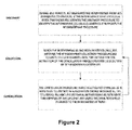
- Figure 2 shows the three phases in which the invention is structured: discovery, collection and cancellation.
- the discovery phase is intended to discover the base stations that can cooperate in the implementation of the proposed interference cancellation method.
- the collection phase is intended for the accumulation of RF fingerprints that may be used and the cancellation phase to eliminate inter-cell interference based on the RF fingerprints reported by the potentially interfering BSs. A detail explanation of each phase will now be described.
- a base station that is capable of supporting uplink interference cancellation identifies the base stations which it can cooperate with. In this sense, it can (but should not necessarily) be considered an extension of the Self Organizing Network feature called Automatic Neighbour Relation (ANR).
- ANR Automatic Neighbour Relation
- the discovery process should happen once the base station is aware with which other base stations it has an enhanced X2 interface implemented (enhanced means that is able to support the exchange of new messages indicated for the proposed invention).
- the base station is time and frequency synchronized with its neighbours, and knows the frame number that is being used by its neighbours.
- the base station uses idle periods (subframes where it has not traffic scheduled to be received or idle RBs) to carry out measurements of the UEs connected to other base stations that are using the same frequency resources. It should be noticed that BS2 has no way to know which BS the transmitting UE is connected to.
- the BS2 sends a message to the base stations it has X2 interface available requesting information about the signal that produced the interference.
- the RF Request message includes the frame and subframe number of the interfering signals and the Resource Blocks (RBs) used.
- the base stations should, for the support of this phase, keep a record of the RF fingerprints of a relatively low number of received subframes (e.g., one frame).
- RF Response message which generally includes several information elements:
- the querying base station has to store and process their responses in order to estimate which one is the main source for the interference.
- the uncertainty can be easily solved if the number of potential interferers is low and the traffic activity factor is also low.
- the outcome of this phase is a list of base station that may be source of uplink interference when UEs are connected to them.
- These base stations constitute a RF IC Group (The procedures detailed in the next phases are limited to the members of the RF IC Group).
- the RF IC Group has an identifier, which should be chosen to avoid any potential uncertainty (the identifier of the cell that has initiated the discovery phase can be used for these purposes), and each BS in the group is also provided an internal identifier.
- base stations have two fulfil two additional conditions:
- each base station that supports the RF fingerprint based interference cancellation should, after the discovery phase has been carried out, lead its own RF IC Group.
- One base station can be part of more than one RF IC Group as a cooperating one, but can only lead a RF IC Group.
- the discovery phase is repeated periodically in order to determine if new base stations in the network may be cause significant interference (the BS should be aware that there are new base stations as they should be identified in the ANR SON process).
- the base station collects pairs of RF fingerprints from a single UE connected to a different base station in its RF IC Group.
- This phase is activated when the base station has idle or partially idle uplink subframes.
- the general process is illustrated in the following figure, which for sake of simplicity only two BSs, querying and queried, are represented:
- the common part of the proposed RF fingerprint to be exchanged in response to a query is composed by two components.
- the first one is an estimation of the sampled channel impulse response, which a complex vector of size Nc, being the number of subcarriers.
- Nc the number of subcarriers.
- the channel response can be estimated by the base station from the Reference Signals transmitted by the UE.
- the second component is a sample of the received signal in the frequency domain Y. This can be produced as the outcome of the DFT at the receiver as indicated in figure 5 .
- the received signal Y at each BS is the result of the convolution of the input of the IDFT X in the transmitter with the channel frequency response H. Because X can change in every subframe, even if the channel remains the same, the interference generated may be different, so the channel response could be not enough to predict the interference generated. For this reason both the channel response estimation and the received signal are part of the RF fingerprint.
- both components to be incorporated in the RF fingerprint can be estimated and sent before the full demodulation of the signal has happened in the receiver.
- the stored RF fingerprint in the queried base station incorporates at least the sample channel impulse response, and before entering the RF fingerprint in the register or database it can be pre-processed in order to reduce storage requirements or coping with partial measurements.
- the collection phase can be coordinated to be carried out simultaneously by several base stations, in such a way that several of them schedule empty subframes simultaneously.
- One of the main parameters used to control the collection process is the minimum value of the interfering signal received in BS2 that is required to collect the RF fingerprint reported by the interfering base station.
- the cancellation phase gets activated when an UE connected to the base station is considered to be heavily interfered (this can be easily determined by the base station, when contrasting the received signal level with its quality, and the supporting procedure is not part of the proposed invention). Then, the base station may identify which are the most likely candidate base stations to provoke the interference (this is not strictly required if the number of potential interferers is relatively low). For these purposes, the invention can implement a separate process, which would rank the likelihood of the base stations in the RF IC Group to be the most interfering one.
- the ranking process can be based on a cost function that takes into account all the information that is available at the receiving base station or in a heuristic process.
- the basic factor in the function would be the similarity of the estimated interference with respect to the fingerprints stored in the compilation phase.
- the process to estimate the interference is represented figure 7 .
- the base station may use the non-scheduled UL subframes/RBs to measure the interference and compare it with the RF fingerprints in order to determine which base station the main interfering UE is connected to.
- the base station sends a RF Cancellation Request message to the base stations that the potentially interfering UEs are connected.
- This message indicates the periodicity the RF fingerprints should be sent (one per each subframe or with a lower frequency).
- the queried base station may accept or reject the cooperation, or may propose different conditions to be applied.
- Figure 8 illustrates the process for those base stations that agree to cooperate.
- RF fingerprints are sent by cooperating base stations ideally every subframe, independently of whether the UE is being scheduled or not (indicating when the potentially interfering UE is not transmitting will help to verify that the base stations queried is the correct one).
- the latency incurred in the transmission process should be as low as possible (ideally, lower than 1 ms).
- the base station Based on the reported RF fingerprint, the base station selects the associated RF fingerprint most likely to represent the interference. This selection may take into account other information reported by the interfering cell, like the UE location information (if available) or the success rate of previous IC processes (if stored in the database). The basic mechanism, however, should be the minimization of a measure of the distance between the reported RF fingerprint and the ones stored in the base stations database. A ranking of likely fingerprints is the outcome of this process.
- Figure 9 illustrates the process that is carried once the interfering fingerprint has been selected.
- the interfering signal should be generated in the Interfering signal generation module.
- the module generates the channel response for the link between the UE and the reporting base stations. This can be done by convoluting the reported sampled channel by the DFT matrix.
- the channel response H1 and the reported sample of the received signal in the frequency domain Y 1 are used then for obtaining an estimation of original input signal in the frequency domain X 1 .
- X 1 is then convoluted by the channel response of the selected RF fingerprint H 2 , in order to obtain an estimation of the interfering signal in the frequency domain Y 2 .
- the different RF fingerprints are processed in the Interfering signal generation module to produce a combined interference signal.
- the process can be improved including an additional loop, where the demodulation and decoding of the signal is performed both before and after interference cancellation, in order to prevent that the latter may result in a quality loss.
- the effectiveness of the IC process is incorporated to the RF fingerprints register or database with an indication of the performance improvement achieved with the use of the interference cancellation process. It is very likely that the invention becomes more effective when the interfering UE is static or with low mobility (e.g., when it is located indoors).
- the base station processing capabilities are enhanced with the incorporation of the register or database to accumulate the RF fingerprint pairs. Also, the receiver is modified to incorporate the proposed IC process.
- IP layer of X2 only supports point-to-point transmission for delivering X2-AP message.
- the invention would benefit from the support of multicasting messages.
Abstract
Description
- The present invention generally relates to wireless communication, and more particularly to a method and system for cancelling the uplink interference in a wireless network.
- The invention refers also to a computer program product configured to perform some of the steps of the proposed method for cancelling said uplink interference.
- One of the expected ways to improve the performance of wireless mobile systems in areas where the interference is the limiting factor is the use of advanced receivers that support interference cancellation (IC) techniques. For the implementation of interference cancellation (e.g., when implementing Successive Interference Cancellation (SIC), based in the principle of detect, decode and cancel a strong interferer and continue in the same way until desired signal can be decoded), it is sometimes necessary that the receiver is able to properly estimate the interfering channel and is aware of the modulation and coding scheme used by the interferer (other information, like the scrambling code used, may be also required).
- In some cases, the information required for IC implementation is naturally available at the receiver. This is the case, for example, of intra-cell multi user Multiple Input Multiple Output (MIMO) (MU-MIMO), where the spatial multiplexing of streams from different UEs is carried out. The receiving base station (BS) is aware of the modulation and coding scheme used by each UE and can apply the SIC principle. Also, the signals arrive to the receiver synchronized and the Reference Signals used for channel estimation (DM-RS) are guaranteed to use different cyclic shifts, so they remain orthogonal. Uplink MU-MIMO is supported by advanced wireless systems like Long Term Evolution (LTE) or IEEE 802.11ac.
- However, the use of interference cancellation techniques for eliminating the inter cell interference in the uplink faces significant challenges. In this case, it cannot be guaranteed that the DM-RS are orthogonal. The situation to solve is represented in
figure 1 . From said figure it can be seen that the interference originated by UEs connected to other cells may be cancelled in the serving cell basically if one of two possible situations happens: - The interference level is very low compared with the UE signal level (i.e., S/I >> 0 dB). In this case, however, eliminating the interference provides reduced benefits.
- The interference level is very high compared with the UE signal level (i.e., S/I << 0 dB). This situation is expected to happen only in a limited set of situations, like when an UE served by a macrocell is in the coverage area of a CSG femtocell, or a femtocell served UE operates in the Cell Range Extension (CRE) area.
- The proposed invention is expected to serve UEs located in areas where none of these two situations is relevant, i.e., when the level of the UE signal and of the interference are similar. In those cases, the estimation of the channel of the interfering signal cannot be properly carried out and the result is a limited effectiveness of the interference cancellation mechanisms.
- The proposed solution for overcoming this kind of problems is to extend the MU-MIMO principle to more than one cell or base station. For this to be possible, it is required to carry out the joint processing of the signals received by the different base stations and, consequently, to implement a cooperation mechanism between cells. These kinds of techniques are referred in the technical literature as CoMP (Cooperative Multipoint Transmission and Reception). CoMP, however, comes with an associated cost, which in the case of the uplink means that the quantized baseband signals should be transmitted to a common processing point.
- The implementation of CoMP techniques in the uplink to overcome cell edge interference problems actually faces a number of challenges:
- The use of uplink intra-cell MU-MIMO increases inter-cell interference. In the worst case scenario, the gain obtained in terms of reuse of the same resources may be lost due to the increase of intercell interference.
- Inter-cell MU-MIMO would require complex coordination mechanisms between the cooperating cells, so the interference cancellation procedures can be performed. It would also require high capacity, low latency links between the cooperating cells (otherwise, it should be restricted to intra site MU-MIMO).
- Inter-cell MU-MIMO would require to sacrifice part of the frequency selective scheduling gain that can be obtained with LTE as the channels to the cells involved may have completely different characteristics and the resources blocks selection cannot be optimized simultaneously.
- Support of inter cell uplink CoMP joint processing would also require more advanced terminals and possibly preclude the use of legacy ones (e.g., Release 8 & 9 UEs).
- The proposed invention is intended to provide similar benefits to those that can be obtained with uplink CoMP techniques but with a reduced complexity, both in the terminal and in the network. For achieving these objectives, it is proposed to use mechanism that has been extensively used for estimating the location of the mobile terminals, i.e., the reporting of radio frequency (RF) fingerprints. Moreover, the invention is compatible with both LTE and LTE Advanced radio interfaces without modifications. It may require, however, changes in the protocols.
- The invention proposes a solution for facilitating the support of interference cancellation techniques in the uplink of a wireless cellular system, such as LTE, LTE Advanced, etc. by means of RF fingerprints collection by the base stations and the exchange of RF fingerprints during active calls. This mechanism would allow to solve some of the problems indicated above and would be complementary to similar mechanisms proposed for the downlink.
- According to a first aspect it is provided a method for cancelling uplink interference in a wireless network, comprising as commonly in the art measuring by an interfered base station the uplink interference provoked over at least one interfered user device wirelessly connected thereto, and when said uplink interference exceeds a given threshold performing a cancellation process.
- On contrary of the known proposals, and in a characteristic manner, the interfered base station to perform said cancellation process comprises the following steps:
- a) discovering and identifying at least one potentially interfering serving base station to which at least one interfering user device of a plurality of interfering user devices is wirelessly connected;
- b) requesting to said at least one discovered and identified potentially interfering serving base station the RF fingerprints of the one or more interfering user devices served thereby and using the same frequency resource blocks of said interfered base station;
- c) receiving, as a result of said requesting, at least the RF fingerprint of said at least one interfering user device;
- d) consulting said received RF fingerprint in a register which includes information regarding several RF fingerprints of other user devices and at least information regarding the level of interference caused on said interference base station when not being served thereby;
- e) selecting as a result of said consulting the RF fingerprint more similar to the received one and taking the information of level of interference associated thereto; and
- f) using said taken level of interference information for performing said cancelling of said uplink interference.
- The requested RF fingerprints of the one or more interfering user devices are also stored in the register or database and then said register is also updated. Before entering the RF fingerprints in the register or database these preferably are pre-processed, for instance by compressing their information data, in order to reduce storage requirements or coping with partial measurements. This processing would be required, for example, to select those frequency sections where no multiple-cell interference happens.
- The stored RF fingerprint includes a measure of the complex frequency response of the radio channel between the user device and the base station (e.g., the outcome of the channel estimator in the base station receiver), as well as other metrics of the radio interface such as a timing advance, a location information from a user device GPS data, reports containing data from other RATs provided by the user device or information reports containing WiFi signals received by the user device. As cells from different vendors may have different outputs from the channel receiver, a common format that can be easily implemented by most if not all of them could be defined.
- According to an embodiment, the measuring step is performed during idle periods of said interfered based station.
- The RF fingerprints are composed preferably by several layer 1 features of the uplink connection that can be reported by the base stations, like the channel estimation, the received signal power, the applied timing advance (TA) or the scheduled modulation and coding scheme. The RF fingerprint is reported per user device and the concept managed in the invention is different to the one used for location or access control purposes.
- For the support of the link between the cooperating base stations an X2 interface can be reused. However, new messages including a frame and a subframe number of the information regarding the level of interference and the frequency resource blocks (RBs) used are incorporated to support the different procedures. In an alternative implementation, a centralized architecture like Cloud RAN, where the baseband processing elements of several base stations are concentrated in a single location, can also be used meeting the requirements of the invention, without requiring the support of the X2 interface.
- According to another embodiment, the discovering and the identifying of the at least one potentially interfering serving base station is performed periodically every certain period of time.
- According to a second aspect it is provided a system for cancelling uplink interference in a wireless network, wherein an interfered base station comprises measuring and processing means for performing a measure of the uplink interference provoked over at least one interfered user device wirelessly connected thereto and for performing a cancellation process. On contrary of the known proposals the interfered base station is configured for implementing the method of the first aspect by means of said processing means and by means of a memory accessible thereby which stores said register.
- According to a third aspect it is provided a computer program product comprising instructions that when executed in a computer are configured to perform steps a), b), d), e) and f) of the method of the first aspect.
- With the proposed invention, it can be overcome the inter-cell interference, which is the main limitation for the uplink capacity in LTE systems. Moreover, the invention does not depend on the user device capabilities, e.g., it can be applied for legacy terminals that do not support uplink MIMO and the base stations that support ABS elClC procedures will support it without significant changes. Although it has been adapted to its use in LTE, the basic principles of the invention could be applied to other similar technologies like HSUPA for instance.
- Finally, the RF fingerprints stored by the base station may be reused for other purposes, like optimizing the scheduling decisions (e.g., supporting coordinated frequency selective scheduling or improving the precoding in order to minimize inter-cell interference).
- The previous and other advantages and features will be more fully understood from the following detailed description of embodiments, with reference to the attached, which must be considered in an illustrative and non-limiting manner, in which:
-
Figure 1 shows a common situation of uplink inter-cell interference. -
Figure 2 is a flow chart describing the relationship of the three phases proposed by the method of the present invention according to the first aspect. -
Figure 3 is an illustration of the process that is performed during the proposed discovery phase according to an embodiment of the present invention. -
Figure 4 is an illustration of the process that is performed during the proposed collection phase according to an embodiment of the present invention. -
Figure 5 is an illustration of the different modules used in a transmission-receiving procedure in a common OFDM system. -
Figure 6 is an illustration of the preprocessing that has to be done before entering the RF fingerprints in the database according to an embodiment of the present invention. -
Figure 7 is an illustration of the process to estimate the interference according to an embodiment of the present invention. -
Figure 8 is an illustration of the process that is performed when a serving BS agrees to collaborate with the interference proposed cancellation method. -
Figure 9 is an illustration of the process that is performed once an interfering RF fingerprint has been selected. -
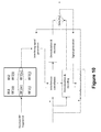
Figure 10 is an illustration of the process that is performed by including a demodulation and decoding process of the signal before and after the interference cancellation to improve the proposed cancellation method. -
Figure 2 shows the three phases in which the invention is structured: discovery, collection and cancellation. The discovery phase is intended to discover the base stations that can cooperate in the implementation of the proposed interference cancellation method. The collection phase is intended for the accumulation of RF fingerprints that may be used and the cancellation phase to eliminate inter-cell interference based on the RF fingerprints reported by the potentially interfering BSs. A detail explanation of each phase will now be described. - In the discovery phase a base station that is capable of supporting uplink interference cancellation identifies the base stations which it can cooperate with. In this sense, it can (but should not necessarily) be considered an extension of the Self Organizing Network feature called Automatic Neighbour Relation (ANR). The discovery process should happen once the base station is aware with which other base stations it has an enhanced X2 interface implemented (enhanced means that is able to support the exchange of new messages indicated for the proposed invention). The base station is time and frequency synchronized with its neighbours, and knows the frame number that is being used by its neighbours.
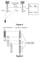
- In
Figure 3 , when the process is initiated, the base station (BS2) uses idle periods (subframes where it has not traffic scheduled to be received or idle RBs) to carry out measurements of the UEs connected to other base stations that are using the same frequency resources. It should be noticed that BS2 has no way to know which BS the transmitting UE is connected to. - For that reason, if the signal level measured exceeds a given threshold, associated with the maximum level of interference acceptable, the BS2 sends a message to the base stations it has X2 interface available requesting information about the signal that produced the interference. The RF Request message includes the frame and subframe number of the interfering signals and the Resource Blocks (RBs) used. The base stations should, for the support of this phase, keep a record of the RF fingerprints of a relatively low number of received subframes (e.g., one frame).
- Then, the asked base stations respond with a RF Response message, which generally includes several information elements:
- Indication of scheduled RBs in the frame/subframe queried. If the base station did not have any UE in the RBs indicated in the Request, it reports a null value.
- Channel complex frequency response per receiver antenna, as the parameters of the Digital Fourier Transform (FT) of the channel response of the Demodulation Reference Signal (DM-RS).
- Received power level.
- Timing advance of the transmitting UE.
- Modulation and coding scheme used.
- If available, information about the UE location, like those reported by the UE (if it has GPS activated) or obtained by the network.
- If available, RF information from other networks (e.g., other RATs, Wi-Fi...).
- It can occur that several base stations may answer this message, so the querying base station has to store and process their responses in order to estimate which one is the main source for the interference. The uncertainty can be easily solved if the number of potential interferers is low and the traffic activity factor is also low.
- The outcome of this phase is a list of base station that may be source of uplink interference when UEs are connected to them. These base stations constitute a RF IC Group (The procedures detailed in the next phases are limited to the members of the RF IC Group). The RF IC Group has an identifier, which should be chosen to avoid any potential uncertainty (the identifier of the cell that has initiated the discovery phase can be used for these purposes), and each BS in the group is also provided an internal identifier.
- To be part of the RF IC Group, base stations have two fulfil two additional conditions:
- The latency in the exchange of X2 messages between the BS and the lead RF IC Group base station should be compatible with the one required in the cancellation phase.
- The base station and the lead RF IC Group BS should be time and frequency synchronized.
- In this way, each base station that supports the RF fingerprint based interference cancellation should, after the discovery phase has been carried out, lead its own RF IC Group. One base station can be part of more than one RF IC Group as a cooperating one, but can only lead a RF IC Group.
- The discovery phase is repeated periodically in order to determine if new base stations in the network may be cause significant interference (the BS should be aware that there are new base stations as they should be identified in the ANR SON process).
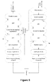
- In this phase, also during idle periods the base station collects pairs of RF fingerprints from a single UE connected to a different base station in its RF IC Group. This phase is activated when the base station has idle or partially idle uplink subframes. The general process is illustrated in the following figure, which for sake of simplicity only two BSs, querying and queried, are represented:
- The collection of RF fingerprints is activated by the querying base station sending a RF Collection Request message to all the base stations that have been identified as potential interferers in the previous phase. Two different procedures are foreseen:
- Broadcast procedure:
- In the first one the message is sent to all the base stations in the RF IC Group by the lead RF IC Group base station. A broadcast address in the message header indicates that it is sent to all the base stations.
- The Request sent indicates the set of frames/subframes the RF fingerprint collection will take place. This is proposed to be made by means of a bitmap, similar to the one used for the indication of Absolut Blank Subframes (ABS) for enhanced ICIC. Subframes marked with a 1 are those where the base station will measure the RF fingerprint, whilst those marked with a 0 will not be measured. The queried can select those subframes that better fir their scheduling decisions. It is in the interest of the procedure that the queried base stations do not transmit in all the subframes the base station is going to measure, so better estimations of the interference associated to a given UE are produced.
- Selective procedure:
- In this case the querying base station sends different messages to each queried base station. This more advanced method would require the use of three values per subframe in the map. +1 indicates the subframe will be measured and that the queried can transmit the RF fingerprint of the UE(s) that it has scheduled in it. 0 marked subframes indicate that the querying base station will not measure the RF fingerprint. -1 marked subframes indicate that the queried BS cannot schedule UEs in it, in order to guarantee that the RF fingerprint measured in the querying base station (which corresponds to an UE connected to a third base station) is not interfered.
- In the subframes that will be measured the base stations queried schedule UEs that are on the cell edge (e.g., UEs that are transmitting at full power).
- In the invention, the RF fingerprint(s) to be reported fulfil a number of requirements:
- It is useful for being employed in the interference cancellation process carried out in the next phase.
- It requires a high capacity for its transmission through the modified X2 interface.
- It incorporates an estimation of the reliability of the fingerprint reported.
- It is assumed that the channel response should be constant over a subframe period.
- Broadcast procedure:
- The common part of the proposed RF fingerprint to be exchanged in response to a query is composed by two components. The first one is an estimation of the sampled channel impulse response, which a complex vector of size Nc, being the number of subcarriers.

- This vector can be estimated from the channel frequency response
H , as:
N being the size of the FFT. The channel response can be estimated by the base station from the Reference Signals transmitted by the UE. The DFT matrix F can be defined as:
Where each matrix element is given by:
- The second component is a sample of the received signal in the frequency domain Y. This can be produced as the outcome of the DFT at the receiver as indicated in
figure 5 . - The received signal Y at each BS is the result of the convolution of the input of the IDFT X in the transmitter with the channel frequency response H. Because X can change in every subframe, even if the channel remains the same, the interference generated may be different, so the channel response could be not enough to predict the interference generated. For this reason both the channel response estimation and the received signal are part of the RF fingerprint.
- It should be noticed that both components to be incorporated in the RF fingerprint can be estimated and sent before the full demodulation of the signal has happened in the receiver.
- As explained before, the stored RF fingerprint in the queried base station incorporates at least the sample channel impulse response, and before entering the RF fingerprint in the register or database it can be pre-processed in order to reduce storage requirements or coping with partial measurements.
- The collection phase can be coordinated to be carried out simultaneously by several base stations, in such a way that several of them schedule empty subframes simultaneously.
- One of the main parameters used to control the collection process is the minimum value of the interfering signal received in BS2 that is required to collect the RF fingerprint reported by the interfering base station.
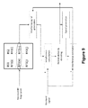
- Finally, the cancellation phase gets activated when an UE connected to the base station is considered to be heavily interfered (this can be easily determined by the base station, when contrasting the received signal level with its quality, and the supporting procedure is not part of the proposed invention). Then, the base station may identify which are the most likely candidate base stations to provoke the interference (this is not strictly required if the number of potential interferers is relatively low). For these purposes, the invention can implement a separate process, which would rank the likelihood of the base stations in the RF IC Group to be the most interfering one.
- The ranking process can be based on a cost function that takes into account all the information that is available at the receiving base station or in a heuristic process. The basic factor in the function would be the similarity of the estimated interference with respect to the fingerprints stored in the compilation phase. The process to estimate the interference is represented
figure 7 . - Alternatively, another option is for the base station to use the non-scheduled UL subframes/RBs to measure the interference and compare it with the RF fingerprints in order to determine which base station the main interfering UE is connected to.
- Then, upon the condition of high interference being met, the base station sends a RF Cancellation Request message to the base stations that the potentially interfering UEs are connected. This message indicates the periodicity the RF fingerprints should be sent (one per each subframe or with a lower frequency). The queried base station may accept or reject the cooperation, or may propose different conditions to be applied.
Figure 8 illustrates the process for those base stations that agree to cooperate. - RF fingerprints are sent by cooperating base stations ideally every subframe, independently of whether the UE is being scheduled or not (indicating when the potentially interfering UE is not transmitting will help to verify that the base stations queried is the correct one). The latency incurred in the transmission process should be as low as possible (ideally, lower than 1 ms).
- Based on the reported RF fingerprint, the base station selects the associated RF fingerprint most likely to represent the interference. This selection may take into account other information reported by the interfering cell, like the UE location information (if available) or the success rate of previous IC processes (if stored in the database). The basic mechanism, however, should be the minimization of a measure of the distance between the reported RF fingerprint and the ones stored in the base stations database. A ranking of likely fingerprints is the outcome of this process.
-
Figure 9 illustrates the process that is carried once the interfering fingerprint has been selected. Once the RF fingerprint that represents the interference is chosen, the interfering signal should be generated in the Interfering signal generation module. For these purposes, the module generates the channel response for the link between the UE and the reporting base stations. This can be done by convoluting the reported sampled channel by the DFT matrix. The channel response H1 and the reported sample of the received signal in the frequency domain Y1 are used then for obtaining an estimation of original input signal in the frequency domain X1 . - X1 is then convoluted by the channel response of the selected RF fingerprint H2 , in order to obtain an estimation of the interfering signal in the frequency domain Y2 .
- If more than one base station is queried, the different RF fingerprints are processed in the Interfering signal generation module to produce a combined interference signal.
- The process can be improved including an additional loop, where the demodulation and decoding of the signal is performed both before and after interference cancellation, in order to prevent that the latter may result in a quality loss.
- Finally, the effectiveness of the IC process is incorporated to the RF fingerprints register or database with an indication of the performance improvement achieved with the use of the interference cancellation process. It is very likely that the invention becomes more effective when the interfering UE is static or with low mobility (e.g., when it is located indoors).
- In order to support the invention, the base station processing capabilities are enhanced with the incorporation of the register or database to accumulate the RF fingerprint pairs. Also, the receiver is modified to incorporate the proposed IC process.
- As explained before new messages are incorporated to the X2 interface in order to support the invention in the three different phases. As X2AP has been designed as an extensible protocol, no major problems are foreseen for the support of the new messages and new information elements. However, it should be taken into account that the invention requires X2 Transport Protocol to expand in two different areas:
- The new procedures required by the present invention are specific to a given UE but are not related to mobility support. It is proposed to include a new class of procedures devoted to UE operations support, which would encompass mobility support procedures. This expansion is likely to happen in order to support CoMP procedures.
- Additionally, the actual version of X2 signalling transport [TS 36.422 V10.1.0 (2011-06) (Release 10)] IP layer of X2 only supports point-to-point transmission for delivering X2-AP message. The invention would benefit from the support of multicasting messages.
- The embodiments described above are to be understood as a few illustrative examples of the present invention. It will be understood by those skilled in the art that various modifications, combinations and changes may be made to the embodiments without departing from the scope of the present invention. In particular, different part solutions in the different embodiments can be combined in other configurations, where technically possible.
Claims (14)
- A method for cancelling uplink interference in a wireless network, comprising measuring by an interfered base station (BS2) the uplink interference provoked over at least one interfered user device (UE2) wirelessly connected thereto, and when said uplink interference exceeds a given threshold performing a cancellation process, characterized in that said interfered base station (BS2) to perform said cancellation process comprises the following steps:a) discovering and identifying at least one serving base station (BS1) to which at least one interfering user device (UE1) of a plurality of interfering user devices is wirelessly connected;b) requesting to said at least one discovered and identified serving base station (BS1) the RF fingerprints of the one or more interfering user devices served thereby and using the same frequency resource blocks (RB) of said interfered base station (BS2);c) receiving, as a result of said requesting, at least the RF fingerprint of said at least one interfering user device (UE1);d) consulting said received RF fingerprint in a register which includes information regarding several RF fingerprints of other user devices and at least information regarding the level of interference caused on said interference base station (BS2) when not being served thereby;e) selecting as a result of said consulting the RF fingerprint more similar to the received one and taking the information of level of interference associated thereto; andf) using said taken level of interference information for performing said cancelling of said uplink interference.
- A method according to claim 1, further comprising storing the requested RF fingerprints of the one or more interfering user devices and updating said register.
- A method according to claim 1, wherein said measuring is performed during idle periods of said interfered base station (BS2).
- A method according to claim 3, wherein said requesting is performed by means of sending a message through at least an enhanced X2 interface.
- A method according to claim 3, wherein said requesting is performed by means of a centralized baseband processing.
- A method according to claim 4 or 5, wherein said message sent includes a frame and a subframe number of the information regarding the level of interference and of the frequency resource blocks (RBs) used.
- A method according to claim 6, wherein said message is sent either in a broadcast manner or in a selective manner.
- A method according to claim 1, wherein said discovering and identifying of the at least one potentially interfering serving base station (BS1) is performed periodically every certain period of time.
- A method according to claim 1, wherein the RF fingerprints are composed by a set of layer 1 features of the uplink connection, said set of layer 1 features being at least a radio channel estimation of said at least one interfering user device (UE1) and each of said base stations (BS1 and BS2), the information regarding the level of interference in the interfered base station (BS2), the applied timing advance (TA) of the at least one interfering user device (UE1) or the scheduled modulation and coding
- A method according to claim 2, wherein said RF fingerprints are pre-processed by at least compressing their information data before being stored.
- A method according to claim 10, wherein said stored RF fingerprints include a measure of the frequency response of the radio channel.
- A method according to claim 11, wherein said stored RF fingerprints further includes a set of metrics of the radio channel, being said set of metrics at least one of a timing advance, a location information from a user device GPS data, reports containing data from other RATs provided by the user device or information reports containing WiFi signals received by the user device.
- A system for cancelling uplink interference in a wireless network, comprising in an interfered base station (BS2) measuring and processing means for performing a measure of uplink interference provoked over at least one interfered user device (UE2) wirelessly connected thereto and for performing a cancellation process, characterised in that it is configured for implementing the method of claim 1 by means of said processing means and of a memory accessible thereby and storing said register.
- A computer program product comprising instructions that when executed in a computer are configured to perform steps a), b), d), e) and f) of the method of claim 1 to cancel uplink interference in a wireless network.
Priority Applications (3)
| Application Number | Priority Date | Filing Date | Title |
|---|---|---|---|
| EP13382061.3A EP2773055B1 (en) | 2013-02-27 | 2013-02-27 | Method, system and computer program for cancelling uplink interference in a wireless network |
| ES13382061.3T ES2689378T3 (en) | 2013-02-27 | 2013-02-27 | Method, system and computer program for canceling uplink interference in a wireless network |
| US14/190,871 US9338670B2 (en) | 2013-02-27 | 2014-02-26 | Method, system and computer program for cancelling uplink interference in a wireless network |
Applications Claiming Priority (1)
| Application Number | Priority Date | Filing Date | Title |
|---|---|---|---|
| EP13382061.3A EP2773055B1 (en) | 2013-02-27 | 2013-02-27 | Method, system and computer program for cancelling uplink interference in a wireless network |
Publications (2)
| Publication Number | Publication Date |
|---|---|
| EP2773055A1 true EP2773055A1 (en) | 2014-09-03 |
| EP2773055B1 EP2773055B1 (en) | 2018-07-04 |
Family
ID=47844240
Family Applications (1)
| Application Number | Title | Priority Date | Filing Date |
|---|---|---|---|
| EP13382061.3A Not-in-force EP2773055B1 (en) | 2013-02-27 | 2013-02-27 | Method, system and computer program for cancelling uplink interference in a wireless network |
Country Status (3)
| Country | Link |
|---|---|
| US (1) | US9338670B2 (en) |
| EP (1) | EP2773055B1 (en) |
| ES (1) | ES2689378T3 (en) |
Families Citing this family (4)
| Publication number | Priority date | Publication date | Assignee | Title |
|---|---|---|---|---|
| US10164683B2 (en) * | 2014-08-08 | 2018-12-25 | Lg Electronics Inc. | Method for receiving interference cancellation |
| US10070253B2 (en) * | 2015-12-29 | 2018-09-04 | Sk Planet Co., Ltd. | Method, apparatus, and recording medium for radio fingerprint map construction and location tracking |
| KR102514593B1 (en) * | 2015-12-29 | 2023-03-27 | 에스케이플래닛 주식회사 | Method and Apparatus for Building RF Fingerprint |
| EP3786864A1 (en) * | 2019-08-27 | 2021-03-03 | Siemens Healthcare GmbH | Combined indoor and outdoor tracking using machine learning |
Citations (1)
| Publication number | Priority date | Publication date | Assignee | Title |
|---|---|---|---|---|
| WO2011147267A1 (en) * | 2010-05-27 | 2011-12-01 | 刘建 | Method and device for inter cell interference coordination in long term evolution downlink system |
Family Cites Families (25)
| Publication number | Priority date | Publication date | Assignee | Title |
|---|---|---|---|---|
| US8504091B2 (en) * | 2008-02-01 | 2013-08-06 | Qualcomm Incorporated | Interference mitigation for control channels in a wireless communication network |
| US8169931B2 (en) * | 2008-05-21 | 2012-05-01 | Airhop Communications, Inc. | Method and apparatus for base stations and their provisioning, management, and networking |
| US8489028B2 (en) * | 2008-05-22 | 2013-07-16 | Qualcomm Incorporated | System and method to enable resource partitioning in wireless networks |
| US8639996B2 (en) * | 2008-07-11 | 2014-01-28 | Qualcomm Incorporated | Systems and methods for uplink inter-cell interference cancellation using hybrid automatic repeat request (HARQ) retransmissions |
| US8938247B2 (en) * | 2009-04-23 | 2015-01-20 | Qualcomm Incorporated | Sounding reference signal for coordinated multi-point operation |
| WO2011021388A1 (en) * | 2009-08-19 | 2011-02-24 | パナソニック株式会社 | Mobile communication system, network management apparatus, macrocell base station apparatus, and interference control method |
| US8570993B2 (en) * | 2010-05-20 | 2013-10-29 | At&T Mobility Ii Llc | Wi-Fi intelligent selection engine |
| CN103238344A (en) * | 2010-09-10 | 2013-08-07 | 维法尔公司 | RF fingerprints for content location |
| US8457673B2 (en) * | 2010-10-11 | 2013-06-04 | Motorola Mobility Llc | Method and apparatus for radio frequency fingerprint distribution |
| US20120258730A1 (en) * | 2010-11-29 | 2012-10-11 | Qualcomm Incorporated | Estimating access terminal location based on beacon signals from femto cells |
| WO2012138274A1 (en) * | 2011-04-05 | 2012-10-11 | Telefonaktiebolaget L M Ericsson (Publ) | Autonomous maximum power setting based on channel fingerprint |
| WO2013010566A1 (en) * | 2011-07-15 | 2013-01-24 | Telefonaktiebolaget Lm Ericsson (Publ) | Neighbour relations management |
| US20150016561A1 (en) * | 2011-08-17 | 2015-01-15 | CBF Networks, Inc. | Advanced backhaul services |
| WO2013051834A1 (en) * | 2011-10-02 | 2013-04-11 | Lg Electronics Inc. | Method for measurement in wireless communication system and apparatus for the same |
| WO2013065841A1 (en) * | 2011-11-03 | 2013-05-10 | 京セラ株式会社 | Communication control method, mobile communication system, and base station |
| US9723496B2 (en) * | 2011-11-04 | 2017-08-01 | Qualcomm Incorporated | Method and apparatus for interference cancellation by a user equipment using blind detection |
| US9272851B2 (en) * | 2011-11-07 | 2016-03-01 | Mediatek Inc. | Minimization of drive tests for uplink link coverage |
| EP2777187A1 (en) * | 2011-11-11 | 2014-09-17 | Telefonaktiebolaget LM Ericsson (PUBL) | Methods and apparatus for performing measurements in adaptive downlink power transmission |
| US20130225197A1 (en) * | 2012-02-24 | 2013-08-29 | Broadcom Corporation | Low Power Location Beacon |
| US9661601B2 (en) * | 2012-12-13 | 2017-05-23 | Qualcomm Incorporated | Crowdsourcing information in a communication network using small cells |
| US9173200B2 (en) * | 2013-02-28 | 2015-10-27 | Intel Mobile Communications GmbH | Communication terminal, network component, base station and method for communicating |
| US9572055B2 (en) * | 2013-04-09 | 2017-02-14 | Spectrum Effect, Inc. | Uplink interference detection using transmission matrices |
| US9769834B2 (en) * | 2013-05-07 | 2017-09-19 | Spectrum Effect, Inc. | Interference detection with UE signal subtraction |
| US9226200B2 (en) * | 2013-05-10 | 2015-12-29 | Alcatel Lucent | Network assisted interference cancellation |
| US9332465B2 (en) * | 2013-10-15 | 2016-05-03 | Qualcomm Incorporated | Long term evolution interference management in unlicensed bands for wi-fi operation |
-
2013
- 2013-02-27 ES ES13382061.3T patent/ES2689378T3/en active Active
- 2013-02-27 EP EP13382061.3A patent/EP2773055B1/en not_active Not-in-force
-
2014
- 2014-02-26 US US14/190,871 patent/US9338670B2/en not_active Expired - Fee Related
Patent Citations (1)
| Publication number | Priority date | Publication date | Assignee | Title |
|---|---|---|---|---|
| WO2011147267A1 (en) * | 2010-05-27 | 2011-12-01 | 刘建 | Method and device for inter cell interference coordination in long term evolution downlink system |
Non-Patent Citations (1)
| Title |
|---|
| LG ELECTRONICS: "SIC-based ICIC in heterogeneous network", no. R1-100235, 18 January 2010 (2010-01-18), pages 1 - 4, XP002636256, Retrieved from the Internet <URL:http://www.3gpp.org/ftp/tsg_ran/WG1_RL1/TSGR1_59b/Docs/R1-100235.zip> [retrieved on 20110509] * |
Also Published As
| Publication number | Publication date |
|---|---|
| US20140241245A1 (en) | 2014-08-28 |
| EP2773055B1 (en) | 2018-07-04 |
| US9338670B2 (en) | 2016-05-10 |
| ES2689378T3 (en) | 2018-11-13 |
Similar Documents
| Publication | Publication Date | Title |
|---|---|---|
| CN111165066B (en) | Techniques and apparatus for beam failure recovery for a first link using a second link | |
| CN109792284B (en) | Method for assisting beam scanning, tracking and recovery | |
| US10506472B2 (en) | Narrowband reference signals in non-anchor resource blocks | |
| JP7336988B2 (en) | Initiation of Mobility Reference Signal Based on Initial Access Signal Quality | |
| EP3162147B1 (en) | Network node and method therein for reporting channel state information (csi) in a radio communications network | |
| EP3138317B1 (en) | A user equipment, a network node and methods therein for enabling device-to-device (d2d) communication in a radio communications network | |
| CN110249656B (en) | Coupling aperiodic Channel State Information (CSI) Reference Symbol (RS) (CSI-RS) structure with feedback content and reporting timing | |
| EP3051864B1 (en) | Wireless base station, user terminal, and communication control method | |
| EP3127265B1 (en) | A method for estimating signal quality of transmission to a user equipment from a transmission point | |
| KR20130042594A (en) | Providing a beamformed physical downlink control channel (pdcch) on an extension carrier of a mobile communication system | |
| EP3269181B1 (en) | Network nodes, a wireless device and methods therein for enabling transmissions in a wireless communications network | |
| CN111886903A (en) | Skipping periodic measurements to achieve power savings in user equipment | |
| EP3830988A1 (en) | Reference signal monitoring mechanism for remote interference management | |
| CN114846747A (en) | Quasi co-located source selection and indication on sidelink | |
| US9374715B2 (en) | Intercell interference coordination for machine to machine communications | |
| US20230015327A1 (en) | Dynamic scheduling of user equipment (ue) antenna resources | |
| CN111183702A (en) | Supplemental uplink random access channel procedure | |
| US9338670B2 (en) | Method, system and computer program for cancelling uplink interference in a wireless network | |
| CN113366876A (en) | Techniques for performing Minimization of Drive Tests (MDT) | |
| EP3836714B1 (en) | Fbe data transmission method, apparatus, and storage medium | |
| US11483841B2 (en) | DMRS-based beam management for downlink repetition | |
| US20230044975A1 (en) | Multi-cell synchronization for dual connectivity and carrier aggregation | |
| BR102014004594A2 (en) | method and system for canceling uplink interference on a wireless network; and computer program product |
Legal Events
| Date | Code | Title | Description |
|---|---|---|---|
| PUAI | Public reference made under article 153(3) epc to a published international application that has entered the european phase |
Free format text: ORIGINAL CODE: 0009012 |
|
| 17P | Request for examination filed |
Effective date: 20130227 |
|
| AK | Designated contracting states |
Kind code of ref document: A1 Designated state(s): AL AT BE BG CH CY CZ DE DK EE ES FI FR GB GR HR HU IE IS IT LI LT LU LV MC MK MT NL NO PL PT RO RS SE SI SK SM TR |
|
| AX | Request for extension of the european patent |
Extension state: BA ME |
|
| R17P | Request for examination filed (corrected) |
Effective date: 20150223 |
|
| RBV | Designated contracting states (corrected) |
Designated state(s): AL AT BE BG CH CY CZ DE DK EE ES FI FR GB GR HR HU IE IS IT LI LT LU LV MC MK MT NL NO PL PT RO RS SE SI SK SM TR |
|
| GRAP | Despatch of communication of intention to grant a patent |
Free format text: ORIGINAL CODE: EPIDOSNIGR1 |
|
| STAA | Information on the status of an ep patent application or granted ep patent |
Free format text: STATUS: GRANT OF PATENT IS INTENDED |
|
| RIC1 | Information provided on ipc code assigned before grant |
Ipc: H04W 24/02 20090101ALI20180123BHEP Ipc: H04J 11/00 20060101AFI20180123BHEP Ipc: H04W 72/00 20090101ALI20180123BHEP |
|
| INTG | Intention to grant announced |
Effective date: 20180214 |
|
| GRAS | Grant fee paid |
Free format text: ORIGINAL CODE: EPIDOSNIGR3 |
|
| GRAA | (expected) grant |
Free format text: ORIGINAL CODE: 0009210 |
|
| STAA | Information on the status of an ep patent application or granted ep patent |
Free format text: STATUS: THE PATENT HAS BEEN GRANTED |
|
| AK | Designated contracting states |
Kind code of ref document: B1 Designated state(s): AL AT BE BG CH CY CZ DE DK EE ES FI FR GB GR HR HU IE IS IT LI LT LU LV MC MK MT NL NO PL PT RO RS SE SI SK SM TR |
|
| REG | Reference to a national code |
Ref country code: GB Ref legal event code: FG4D |
|
| REG | Reference to a national code |
Ref country code: CH Ref legal event code: EP |
|
| REG | Reference to a national code |
Ref country code: AT Ref legal event code: REF Ref document number: 1015633 Country of ref document: AT Kind code of ref document: T Effective date: 20180715 |
|
| REG | Reference to a national code |
Ref country code: IE Ref legal event code: FG4D |
|
| REG | Reference to a national code |
Ref country code: DE Ref legal event code: R096 Ref document number: 602013039656 Country of ref document: DE |
|
| REG | Reference to a national code |
Ref country code: NL Ref legal event code: MP Effective date: 20180704 |
|
| REG | Reference to a national code |
Ref country code: ES Ref legal event code: FG2A Ref document number: 2689378 Country of ref document: ES Kind code of ref document: T3 Effective date: 20181113 |
|
| REG | Reference to a national code |
Ref country code: LT Ref legal event code: MG4D |
|
| REG | Reference to a national code |
Ref country code: AT Ref legal event code: MK05 Ref document number: 1015633 Country of ref document: AT Kind code of ref document: T Effective date: 20180704 |
|
| PG25 | Lapsed in a contracting state [announced via postgrant information from national office to epo] |
Ref country code: NL Free format text: LAPSE BECAUSE OF FAILURE TO SUBMIT A TRANSLATION OF THE DESCRIPTION OR TO PAY THE FEE WITHIN THE PRESCRIBED TIME-LIMIT Effective date: 20180704 |
|
| PG25 | Lapsed in a contracting state [announced via postgrant information from national office to epo] |
Ref country code: NO Free format text: LAPSE BECAUSE OF FAILURE TO SUBMIT A TRANSLATION OF THE DESCRIPTION OR TO PAY THE FEE WITHIN THE PRESCRIBED TIME-LIMIT Effective date: 20181004 Ref country code: GR Free format text: LAPSE BECAUSE OF FAILURE TO SUBMIT A TRANSLATION OF THE DESCRIPTION OR TO PAY THE FEE WITHIN THE PRESCRIBED TIME-LIMIT Effective date: 20181005 Ref country code: SE Free format text: LAPSE BECAUSE OF FAILURE TO SUBMIT A TRANSLATION OF THE DESCRIPTION OR TO PAY THE FEE WITHIN THE PRESCRIBED TIME-LIMIT Effective date: 20180704 Ref country code: PL Free format text: LAPSE BECAUSE OF FAILURE TO SUBMIT A TRANSLATION OF THE DESCRIPTION OR TO PAY THE FEE WITHIN THE PRESCRIBED TIME-LIMIT Effective date: 20180704 Ref country code: FI Free format text: LAPSE BECAUSE OF FAILURE TO SUBMIT A TRANSLATION OF THE DESCRIPTION OR TO PAY THE FEE WITHIN THE PRESCRIBED TIME-LIMIT Effective date: 20180704 Ref country code: IS Free format text: LAPSE BECAUSE OF FAILURE TO SUBMIT A TRANSLATION OF THE DESCRIPTION OR TO PAY THE FEE WITHIN THE PRESCRIBED TIME-LIMIT Effective date: 20181104 Ref country code: RS Free format text: LAPSE BECAUSE OF FAILURE TO SUBMIT A TRANSLATION OF THE DESCRIPTION OR TO PAY THE FEE WITHIN THE PRESCRIBED TIME-LIMIT Effective date: 20180704 Ref country code: LT Free format text: LAPSE BECAUSE OF FAILURE TO SUBMIT A TRANSLATION OF THE DESCRIPTION OR TO PAY THE FEE WITHIN THE PRESCRIBED TIME-LIMIT Effective date: 20180704 Ref country code: BG Free format text: LAPSE BECAUSE OF FAILURE TO SUBMIT A TRANSLATION OF THE DESCRIPTION OR TO PAY THE FEE WITHIN THE PRESCRIBED TIME-LIMIT Effective date: 20181004 Ref country code: AT Free format text: LAPSE BECAUSE OF FAILURE TO SUBMIT A TRANSLATION OF THE DESCRIPTION OR TO PAY THE FEE WITHIN THE PRESCRIBED TIME-LIMIT Effective date: 20180704 Ref country code: CZ Free format text: LAPSE BECAUSE OF FAILURE TO SUBMIT A TRANSLATION OF THE DESCRIPTION OR TO PAY THE FEE WITHIN THE PRESCRIBED TIME-LIMIT Effective date: 20180704 |
|
| PG25 | Lapsed in a contracting state [announced via postgrant information from national office to epo] |
Ref country code: AL Free format text: LAPSE BECAUSE OF FAILURE TO SUBMIT A TRANSLATION OF THE DESCRIPTION OR TO PAY THE FEE WITHIN THE PRESCRIBED TIME-LIMIT Effective date: 20180704 Ref country code: LV Free format text: LAPSE BECAUSE OF FAILURE TO SUBMIT A TRANSLATION OF THE DESCRIPTION OR TO PAY THE FEE WITHIN THE PRESCRIBED TIME-LIMIT Effective date: 20180704 Ref country code: HR Free format text: LAPSE BECAUSE OF FAILURE TO SUBMIT A TRANSLATION OF THE DESCRIPTION OR TO PAY THE FEE WITHIN THE PRESCRIBED TIME-LIMIT Effective date: 20180704 |
|
| REG | Reference to a national code |
Ref country code: DE Ref legal event code: R097 Ref document number: 602013039656 Country of ref document: DE |
|
| PG25 | Lapsed in a contracting state [announced via postgrant information from national office to epo] |
Ref country code: EE Free format text: LAPSE BECAUSE OF FAILURE TO SUBMIT A TRANSLATION OF THE DESCRIPTION OR TO PAY THE FEE WITHIN THE PRESCRIBED TIME-LIMIT Effective date: 20180704 Ref country code: RO Free format text: LAPSE BECAUSE OF FAILURE TO SUBMIT A TRANSLATION OF THE DESCRIPTION OR TO PAY THE FEE WITHIN THE PRESCRIBED TIME-LIMIT Effective date: 20180704 Ref country code: IT Free format text: LAPSE BECAUSE OF FAILURE TO SUBMIT A TRANSLATION OF THE DESCRIPTION OR TO PAY THE FEE WITHIN THE PRESCRIBED TIME-LIMIT Effective date: 20180704 |
|
| PGFP | Annual fee paid to national office [announced via postgrant information from national office to epo] |
Ref country code: DE Payment date: 20190227 Year of fee payment: 7 Ref country code: ES Payment date: 20190301 Year of fee payment: 7 Ref country code: GB Payment date: 20190227 Year of fee payment: 7 |
|
| PLBE | No opposition filed within time limit |
Free format text: ORIGINAL CODE: 0009261 |
|
| STAA | Information on the status of an ep patent application or granted ep patent |
Free format text: STATUS: NO OPPOSITION FILED WITHIN TIME LIMIT |
|
| PG25 | Lapsed in a contracting state [announced via postgrant information from national office to epo] |
Ref country code: SM Free format text: LAPSE BECAUSE OF FAILURE TO SUBMIT A TRANSLATION OF THE DESCRIPTION OR TO PAY THE FEE WITHIN THE PRESCRIBED TIME-LIMIT Effective date: 20180704 Ref country code: SK Free format text: LAPSE BECAUSE OF FAILURE TO SUBMIT A TRANSLATION OF THE DESCRIPTION OR TO PAY THE FEE WITHIN THE PRESCRIBED TIME-LIMIT Effective date: 20180704 Ref country code: DK Free format text: LAPSE BECAUSE OF FAILURE TO SUBMIT A TRANSLATION OF THE DESCRIPTION OR TO PAY THE FEE WITHIN THE PRESCRIBED TIME-LIMIT Effective date: 20180704 |
|
| 26N | No opposition filed |
Effective date: 20190405 |
|
| PG25 | Lapsed in a contracting state [announced via postgrant information from national office to epo] |
Ref country code: SI Free format text: LAPSE BECAUSE OF FAILURE TO SUBMIT A TRANSLATION OF THE DESCRIPTION OR TO PAY THE FEE WITHIN THE PRESCRIBED TIME-LIMIT Effective date: 20180704 |
|
| REG | Reference to a national code |
Ref country code: CH Ref legal event code: PL |
|
| PG25 | Lapsed in a contracting state [announced via postgrant information from national office to epo] |
Ref country code: MC Free format text: LAPSE BECAUSE OF FAILURE TO SUBMIT A TRANSLATION OF THE DESCRIPTION OR TO PAY THE FEE WITHIN THE PRESCRIBED TIME-LIMIT Effective date: 20180704 Ref country code: LU Free format text: LAPSE BECAUSE OF NON-PAYMENT OF DUE FEES Effective date: 20190227 |
|
| REG | Reference to a national code |
Ref country code: BE Ref legal event code: MM Effective date: 20190228 |
|
| REG | Reference to a national code |
Ref country code: IE Ref legal event code: MM4A |
|
| PG25 | Lapsed in a contracting state [announced via postgrant information from national office to epo] |
Ref country code: LI Free format text: LAPSE BECAUSE OF NON-PAYMENT OF DUE FEES Effective date: 20190228 Ref country code: CH Free format text: LAPSE BECAUSE OF NON-PAYMENT OF DUE FEES Effective date: 20190228 |
|
| PG25 | Lapsed in a contracting state [announced via postgrant information from national office to epo] |
Ref country code: IE Free format text: LAPSE BECAUSE OF NON-PAYMENT OF DUE FEES Effective date: 20190227 |
|
| PG25 | Lapsed in a contracting state [announced via postgrant information from national office to epo] |
Ref country code: FR Free format text: LAPSE BECAUSE OF NON-PAYMENT OF DUE FEES Effective date: 20190228 Ref country code: BE Free format text: LAPSE BECAUSE OF NON-PAYMENT OF DUE FEES Effective date: 20190228 |
|
| PG25 | Lapsed in a contracting state [announced via postgrant information from national office to epo] |
Ref country code: TR Free format text: LAPSE BECAUSE OF FAILURE TO SUBMIT A TRANSLATION OF THE DESCRIPTION OR TO PAY THE FEE WITHIN THE PRESCRIBED TIME-LIMIT Effective date: 20180704 |
|
| PG25 | Lapsed in a contracting state [announced via postgrant information from national office to epo] |
Ref country code: MT Free format text: LAPSE BECAUSE OF NON-PAYMENT OF DUE FEES Effective date: 20190227 Ref country code: PT Free format text: LAPSE BECAUSE OF FAILURE TO SUBMIT A TRANSLATION OF THE DESCRIPTION OR TO PAY THE FEE WITHIN THE PRESCRIBED TIME-LIMIT Effective date: 20181105 |
|
| REG | Reference to a national code |
Ref country code: DE Ref legal event code: R119 Ref document number: 602013039656 Country of ref document: DE |
|
| GBPC | Gb: european patent ceased through non-payment of renewal fee |
Effective date: 20200227 |
|
| PG25 | Lapsed in a contracting state [announced via postgrant information from national office to epo] |
Ref country code: DE Free format text: LAPSE BECAUSE OF NON-PAYMENT OF DUE FEES Effective date: 20200901 Ref country code: GB Free format text: LAPSE BECAUSE OF NON-PAYMENT OF DUE FEES Effective date: 20200227 |
|
| PG25 | Lapsed in a contracting state [announced via postgrant information from national office to epo] |
Ref country code: CY Free format text: LAPSE BECAUSE OF FAILURE TO SUBMIT A TRANSLATION OF THE DESCRIPTION OR TO PAY THE FEE WITHIN THE PRESCRIBED TIME-LIMIT Effective date: 20180704 |
|
| REG | Reference to a national code |
Ref country code: ES Ref legal event code: FD2A Effective date: 20210708 |
|
| PG25 | Lapsed in a contracting state [announced via postgrant information from national office to epo] |
Ref country code: HU Free format text: LAPSE BECAUSE OF FAILURE TO SUBMIT A TRANSLATION OF THE DESCRIPTION OR TO PAY THE FEE WITHIN THE PRESCRIBED TIME-LIMIT; INVALID AB INITIO Effective date: 20130227 |
|
| PG25 | Lapsed in a contracting state [announced via postgrant information from national office to epo] |
Ref country code: ES Free format text: LAPSE BECAUSE OF NON-PAYMENT OF DUE FEES Effective date: 20200228 |
|
| PG25 | Lapsed in a contracting state [announced via postgrant information from national office to epo] |
Ref country code: MK Free format text: LAPSE BECAUSE OF FAILURE TO SUBMIT A TRANSLATION OF THE DESCRIPTION OR TO PAY THE FEE WITHIN THE PRESCRIBED TIME-LIMIT Effective date: 20180704 |