EP2773021A1 - Rotor of interior permanent magnet motor, compressor, and refrigeration and air-conditioning device - Google Patents
Rotor of interior permanent magnet motor, compressor, and refrigeration and air-conditioning device Download PDFInfo
- Publication number
- EP2773021A1 EP2773021A1 EP11874480.4A EP11874480A EP2773021A1 EP 2773021 A1 EP2773021 A1 EP 2773021A1 EP 11874480 A EP11874480 A EP 11874480A EP 2773021 A1 EP2773021 A1 EP 2773021A1
- Authority
- EP
- European Patent Office
- Prior art keywords
- permanent magnet
- rotor
- core
- width
- slits
- Prior art date
- Legal status (The legal status is an assumption and is not a legal conclusion. Google has not performed a legal analysis and makes no representation as to the accuracy of the status listed.)
- Granted
Links
Images


Classifications
-
- H—ELECTRICITY
- H02—GENERATION; CONVERSION OR DISTRIBUTION OF ELECTRIC POWER
- H02K—DYNAMO-ELECTRIC MACHINES
- H02K1/00—Details of the magnetic circuit
- H02K1/06—Details of the magnetic circuit characterised by the shape, form or construction
- H02K1/22—Rotating parts of the magnetic circuit
- H02K1/27—Rotor cores with permanent magnets
- H02K1/2706—Inner rotors
- H02K1/272—Inner rotors the magnetisation axis of the magnets being perpendicular to the rotor axis
- H02K1/274—Inner rotors the magnetisation axis of the magnets being perpendicular to the rotor axis the rotor consisting of two or more circumferentially positioned magnets
- H02K1/2753—Inner rotors the magnetisation axis of the magnets being perpendicular to the rotor axis the rotor consisting of two or more circumferentially positioned magnets the rotor consisting of magnets or groups of magnets arranged with alternating polarity
- H02K1/276—Magnets embedded in the magnetic core, e.g. interior permanent magnets [IPM]
-
- H—ELECTRICITY
- H02—GENERATION; CONVERSION OR DISTRIBUTION OF ELECTRIC POWER
- H02K—DYNAMO-ELECTRIC MACHINES
- H02K2213/00—Specific aspects, not otherwise provided for and not covered by codes H02K2201/00 - H02K2211/00
- H02K2213/03—Machines characterised by numerical values, ranges, mathematical expressions or similar information
-
- H—ELECTRICITY
- H02—GENERATION; CONVERSION OR DISTRIBUTION OF ELECTRIC POWER
- H02K—DYNAMO-ELECTRIC MACHINES
- H02K29/00—Motors or generators having non-mechanical commutating devices, e.g. discharge tubes or semiconductor devices
- H02K29/03—Motors or generators having non-mechanical commutating devices, e.g. discharge tubes or semiconductor devices with a magnetic circuit specially adapted for avoiding torque ripples or self-starting problems
Definitions
- the present invention relates to a rotor of an interior permanent magnet motor, a compressor that includes the rotor, and a refrigerating air-conditioning apparatus that includes the compressor.
- the rotor of the interior permanent magnet motor includes a rotor core that is formed by laminating a plurality of magnetic steel sheets; permanent magnet insertion holes that are formed in an axial direction of the rotor core and are formed in portions corresponding to the sides of a substantially regular polygon centered on the axial center; permanent magnets that are inserted into the permanent magnet insertion holes; a plurality of slits that are formed in a core portion on the outer circumferential side with respect to the permanent magnet insertion holes and are spaced apart along the permanent magnet insertion holes; and outer-side thin portions that are provided between outer side ends of the slits in a radial direction and an outer circumference of the rotor core and each gradually increases its width in the radial direction toward interpolar portions from a magnetic pole center.
- the harmonics of the induced voltage and cogging torque can be reduced by reducing the harmonic components of the magnetic flux density
- Patent Literature 1 Japanese Patent Application Laid-open 2008-167583
- the slit shapes in the rotor of the conventional interior permanent magnet motor described in Patent Literature 1 are such that the width of each of the outer-side thin portions in the radial direction gradually increases toward the interpolar portions from the magnetic pole center and such slit shapes reduce the harmonics of the induced voltage.
- the present invention has been achieved in view of the above and an object of the present invention is to provide a rotor of an interior permanent magnet motor that can reduce torque ripple by reducing the harmonics of the induced voltage, a compressor that includes the rotor, and a refrigerating air-conditioning apparatus that includes the compressor.
- a rotor of an interior permanent magnet motor includes a rotor core; a plurality of permanent magnet insertion holes that are formed in an outer circumferential portion of the rotor core along a circumferential direction; a permanent-magnet end-portion air gap that is formed in each of both end portions of each of the permanent magnet insertion holes; a permanent magnet that is inserted in each of the permanent magnet insertion holes; and a plurality of slits that are formed in a core portion that is on an outer side in a radial direction with respect to each of the permanent magnet insertion holes, wherein three or more of the slits are present in an angular range of 360/(number of poles ⁇ 3) degrees from an interpolar line, which is between magnetic poles of adjacent permanent magnets, and a width of a core present between the permanent-magnet end-portion air gap and the slit and a width of a core present between adjacent slits are such that
- FIGS. 1 and 2 are diagrams for comparison.
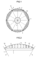
- FIG. 1 is a transverse cross-sectional view of a rotor of an interior permanent magnet motor provided with typical slits and
- FIG. 2 is an enlarged view of a magnetic pole in FIG. 1 .
- a rotor 101 of an interior permanent magnet motor provided with typical slits includes at least a rotor core 2, permanent magnets 3 embedded in the rotor core 2, and a rotating shaft 4 fixed to the rotor core 2.
- the rotor of the interior permanent magnet motor is, in some cases, simply referred to as a rotor.
- the rotor core 2 has a substantially circular shape in transverse cross section and is formed by stamping out thin magnetic steel sheets (for example, non-oriented magnetic steel sheets with a thickness of about 0.1 to 1.0 mm (in which crystal orientations of the crystals are arranged as randomly as possible so as not to exhibit a magnetic property biased in a specific direction of the steel sheets) with a metal die to have a predetermined shape and laminating a predetermined number of (a plurality of) magnetic steel sheets together.
- thin magnetic steel sheets for example, non-oriented magnetic steel sheets with a thickness of about 0.1 to 1.0 mm (in which crystal orientations of the crystals are arranged as randomly as possible so as not to exhibit a magnetic property biased in a specific direction of the steel sheets
- a plurality of (for example, six in the drawings) permanent magnet insertion holes 5 each having, for example, a substantially rectangular shape in transverse cross section are formed, for example, at approximately equal intervals in the circumferential direction.
- a plurality of the permanent magnet insertion holes 5 are formed along the circumferential direction in the outer circumferential portion of the rotor core 2.
- a shaft hole 6, into which the rotating shaft 4 is fitted, is formed in an approximately central portion of the rotor core 2.
- the plate-like permanent magnets 3 are inserted into the six permanent magnet insertion holes 5, respectively, and the six permanent magnets 3 are arranged such that N poles and S poles are alternately arranged in the circumferential direction, thereby configuring the rotor with six poles.
- rare-earth permanent magnets mainly made from neodymium, iron, and boron, or the like are used.
- the permanent-magnet end-portion air gaps 8 reduce leakage flux from the permanent magnets 3 at interpolar lines 9.
- the interpolar line 9 represents a part between magnetic poles of adjacent permanent magnets 3 (halfway between the magnetic poles) or a part between adjacent permanent magnet insertion holes 5.
- a magnetic pole center 10 represents the center of the magnetic pole of each of the permanent magnets 3 in the circumferential direction or represents the center of each of the permanent magnet insertion holes 5 in the circumferential direction.
- An outer circumferential core portion 12 is part of the outer circumferential portion of the rotor core 2 and is a core part on the outer side in the radial direction with respect to the permanent magnet insertion holes 5.
- a plurality of slits 107 are formed at predetermined intervals in the circumferential direction.
- eight slits 107 are formed such that four slits 107 are on each of the right and left sides to be symmetrical about the magnetic pole center 10.
- the magnetic flux from the permanent magnets 3 can be controlled; therefore, it is possible to reduce torque ripple (torque pulsation).
- torque ripple can be reduced due to the effect of the slits 107; however, it is desirable to further reduce torque ripple so as to further reduce noise.
- one factor contributing to degradation of torque ripple is that there is no optimization of the positions at which the slits 107 are arranged, the widths of the cores respectively present between the permanent-magnet end-portion air gaps 8 and the slits 107, and the widths of the cores respectively present between adjacent slits 107.
- the slits 107 approximate the magnetic flux generated from the permanent magnets 3 to a sine wave and reduce the harmonic components of the induced voltage, thereby contributing to a reduction of cogging torque.
- the induced voltage can be given by the time derivative of the magnetic flux interlinking a coil.
- the harmonics of the induced voltage are reduced.
- the induced voltage is given by differentiating the magnetic flux. This means that a change in magnetic flux is large in portions in which the induced voltage is the maximum and a change in magnetic flux is small in portions in which the induced voltage is near 0 volts.
- the portions in which the induced voltage is near 0 volts are affected by the shape of the magnetic pole central portions in which a change in magnetic flux is small, and the portions in which the induced voltage is maximum are affected by the shape of the interpolar portions in which a change in magnetic flux is large.
- the portions in which the induced voltage is maximum are affected by the shape of the interpolar portions in which a change in magnetic flux of the rotor 101 is large; therefore, it is necessary to cause the magnetic flux of the rotor outer circumference of the interpolar portions to change sinusoidally.
- the magnetic pole central portions and the interpolar portions are formed such that magnetic flux increases from the interpolar portions toward the magnetic pole center, because the magnetic pole central portions correspond to the portions in which the induced voltage is near 0 volts, it is desirable to reduce a change in magnetic flux in the magnetic pole central portions. Therefore, it is necessary to make the shape and arrangement of the slits 107 different between the portions near the interpolar portions and the portions near the magnetic pole center.
- each magnetic pole is divided into, for example, three regions and the shape and arrangement of the slits 107 are changed in accordance with each divided region, whereby slits near the interpolar portions and slits near the magnetic pole central portion can be appropriately arranged.
- the specific shape and arrangement of the slits will be described below.
- FIG. 3 is a transverse cross-sectional view of a rotor 1 of the interior permanent magnet motor according to the present embodiment and FIG. 4 is an enlarged view of a magnetic pole portion thereof.
- each magnetic pole of the rotor 1 is divided into three regions, and the shape and arrangement of the slits 7 will be explained for each of the interpolar portions and the magnetic pole central portion.
- each magnetic pole of the rotor 1 is divided into three regions, and each region in an angular range of 360/(number of poles ⁇ 3) degrees from the interpolar line 9 is defined as an interpolar portion 15 and a region on the magnetic pole center 10 side with respect to the interpolar portions 15 (i.e., a region in an angular range larger than 360/(number of poles ⁇ 3) degrees from each of the interpolar lines 9) is defined as a magnetic pole central portion 16.
- a core portion and the slit 7 at 360/(number of poles ⁇ 3) degrees from each of the interpolar lines 9 are defined as a core portion and the slit 7 belonging to the corresponding interpolar portion 9.
- the magnetic flux of the interpolar lines 9 is 0 T and it is necessary to gradually increase the magnetic flux toward the magnetic pole center 10.
- the magnetic flux depends on the size of a core near the rotor outer circumference. In other words, in order to gradually increase the magnetic flux of the interpolar portions 15, it is satisfactory that the size of a core in the rotor outer circumferential portion in each of the interpolar portions 15 gradually increases as the core is closer to the magnetic pole center 10.
- magnetic flux is increased by setting the width of the core present between the permanent-magnet end-portion air gap 8 and the slit 7 and the widths of the cores present between adjacent slits 7 such that the width of a core gradually increases as the core is closer to the magnetic pole center 10 from the corresponding interpolar line 9.
- the width of the core present between the permanent-magnet end-portion air gap 8 and the slit 7 and the widths of the cores present between adjacent slits 7 are respectively defined as A1, A2, and A3 in order from the side of the corresponding interpolar line 9. Therefore, when the relationship A1 ⁇ A2 ⁇ A3 is satisfied, magnetic flux can be increased from the interpolar line 9 toward the magnetic pole center 10. Accordingly, the harmonics of the induced voltage can be reduced and thus torque ripple and noise can be reduced.
- the width of each core is the width in the circumferential direction (rotational direction).
- each of the interpolar portions 15 it is desirable that three or more slits 7 be present in each of the interpolar portions 15.
- the magnetic flux of the rotor surface of each of the interpolar portions 15 can be expressed only at two points; therefore the magnetic flux increases on a line. It is preferable that the magnetic flux be represented by a sinusoidal curve, and when there are three or more slits 7, magnetic flux can be represented by a curve.
- the magnetic pole central portion 16 indicates an angular range larger than 360/(number of magnetic poles ⁇ 3) degrees from each of the interpolar lines 9.
- the magnetic pole central portion 16 is defined as a region in an angular range of 360/(number of magnetic poles ⁇ 3) degrees that is sandwiched between a pair of the interpolar portions 15, each of which is an angular range of 360/(number of magnetic poles ⁇ 3) degrees from the corresponding interpolar line 9 about the axial center of the rotating shaft 4.
- the magnetic pole center 10 is a part at which the magnetic flux density is maximum and corresponds to a part at which the induced voltage is 0 volts.
- the induced voltage being 0 volts indicates that a change in magnetic flux is small, and it is desirable that a change in magnetic flux be gradual in the magnetic pole center 10.
- a change in magnetic flux being made gradual indicates that the core portions present between adjacent slits 7 are made to have approximately the same width, thereby making a change in magnetic flux gradual.
- a change in magnetic flux of the magnetic pole central portion 16 can be made gradual by setting the width of the core on the most magnetic pole center 10 side among the cores present between adjacent slits 7 in each of the interpolar portions 15 (angular range of 360/(number of magnetic poles ⁇ 3) degrees from each of the interpolar lines 9) equal to or more than the widths of the cores present between adjacent slits 7 in the magnetic pole central portion 16 and equal to or less than the interval between the centers of adjacent slits 7 in the magnetic pole central portion 16.
- the magnetic flux toward the magnetic pole center 10 from the corresponding interpolar line 9 is increased by setting the width of the core present between the permanent-magnet end-portion air gap 8 and the slit 7 and the widths of the cores present between adjacent slits 7 such that the width of a core gradually increases as the core is closer to the magnetic pole center 10 from the corresponding interpolar line 9, which is effective particularly when the magnetic force of the permanent magnets 3 flows evenly into the rotor surface.
- the width of the permanent magnets 3 means the width in the circumferential direction.
- the width L of the permanent magnet 3 illustrated in FIG. 4 is smaller than the width W between a pair of the permanent-magnet end-portion air gaps 8 that face each other with the permanent magnet 3 therebetween (L ⁇ W)
- the widths of the cores present between adjacent slits 7 in each of the interpolar portions 15 are such that the width of a core gradually increases as the core is closer to the magnetic pole center 10 from the interpolar line 9, because the widths of the cores in a portion in which the permanent magnet 3 is not present is adjusted, magnetic flux cannot be sufficiently adjusted and thus it is difficult to obtain a sufficient effect.
- the width W between a pair of the permanent-magnet end-portion air gaps 8 specifically means the interval between the ends, which face each other, of a pair of the permanent-magnet end-portion air gaps 8 arranged with the permanent magnet 3 therebetween.
- the width W means the interval between the end of one permanent-magnet end-portion air gap 8 on the other permanent-magnet end-portion air gap 8 side and the end of the other permanent-magnet end-portion air gap 8 on one permanent-magnet end-portion air gap 8 side.
- the width of each of the slits 7 means the width in the circumferential direction.
- the slits 7 are formed of air gaps, the slits 7 have a large effect on the flow of magnetic flux. Therefore, the harmonic components of the induced voltage can be reduced by adjusting the widths of the slits 7.
- the magnetic flux of each of the interpolar portions 15 gradually increase toward the magnetic pole center 10. Because magnetic flux can easily flow in core portions, it is preferable that its width be gradually increased. However, because the widths of the slits 7 are formed of air gaps, magnetic flux does not flow easily. Therefore, if the slits 7 are increased in width, magnetic flux decreases.
- the slits 7 be gradually reduced in width contrary to the cores.
- the widths of the slits 7 in each of the interpolar portions 15 are respectively defined as B1, B2, and B3 in order from the corresponding interpolar line 9, it is preferable to satisfy the relationship B1>B2>B3.
- the slits 7 can be made to have approximately the same width as each other. Furthermore, a change in magnetic flux of the magnetic pole central portion 16 becomes gradual by making the width of the slits 7 in the magnetic pole central portion 16 equal to the width of the slit 7 on the most magnetic pole center 10 side in each of the interpolar portions 15; therefore, the harmonic components of the induced voltage can be reduced. When this is explained with reference to FIG. 4 , t1 becomes equal to t2.
- FIG. 5 is an enlarged view of a magnetic pole portion of a rotor of an interior permanent magnet motor according to a modified example of the present embodiment.
- a slit 7a closest to each of the interpolar lines 9 has an elongated shape in the rotational direction (circumferential direction). In other words, while other slits are long in the radial direction, the slit 7a is long in the rotational direction (circumferential direction).
- the width of the core present between the permanent-magnet end-portion air gap 8 and the slit 7a is defined as A1' and the widths of the cores present between the slits 7 that are present on the magnetic pole center 10 side with respect to the core present between the permanent-magnet end-portion air gap 8 and the slit 7a are respectively defined as A2' and A3' in order, and the relationship A1' ⁇ A2' ⁇ A3' is satisfied as described above.
- Magnetic flux is determined by a core portion having the smallest width and the core portion having the smallest width is formed by the slit 7a, which is long in the rotational direction (circumferential direction), and the permanent-magnet end-portion air gap 8.
- the width of the slit 7a is defined as B1' and the widths of the slits 7 on the magnetic pole center 10 side with respect to the slit 7a are respectively defined as B2' and B3' in order, and the relationship B3' ⁇ B2' ⁇ B1' is satisfied as described above.
- the width B1' of the slit 7a is the size in the circumferential direction (rotational direction).
- the harmonic components of the induced voltage can be reduced and thus torque ripple can be reduced; therefore, the low-noise rotor 1 can be configured.
- the harmonic iron loss is also reduced by reducing the harmonic components of the induced voltage; therefore, the highly efficient rotor 1 can be configured.
- the low-vibration rotor 1 can be configured by reducing torque ripple, the rotor 1 with a long life can be obtained.
- the slits 7 be arranged to extend substantially vertically with respect to the permanent magnet 3. If the slits 7 do not extend substantially vertically with respect to the permanent magnet 3 (in this case, the slits 7 are not parallel to each other), the size between the slits 7 does not become uniform and gradually decreases and thus the magnetic flux density increases. Therefore, magnetic saturation occurs, which causes a reduction in the induced voltage.
- the highly efficient rotor 1 can be obtained.
- the number of magnetic poles of the rotor 1 is, for example, six; however, even if the number of magnetic poles is other than six, the present embodiment is definitely applicable. In such a case, similar effects can be obtained. Specifically, by applying the present embodiment to the rotor in which the number of magnetic poles is other than six, the induced voltage is improved and thus the effect of armature reaction is suppressed, and torque ripple can be reduced. Thus, a highly efficient and low-noise rotor can be configured.
- the interior permanent magnet motor is configured by arranging the rotor 1 to face the inner circumferential side of the stator (not illustrated); however, because the above effect is an effect of reducing torque ripple by the rotor 1, this effect can be obtained regardless of the configuration of the stator (not illustrated), such as the number of slots, the winding method (concentrated winding and distributed winding), and the number of magnetic poles.
- a compressor according to the present embodiment is a compressor that includes the rotor 1.
- a highly efficient and low-noise compressor can be configured by using the motor in which the rotor 1 according to the present embodiment is used with the compressor.
- a refrigerating air-conditioning apparatus is a refrigerating air-conditioning apparatus that includes the compressor described above.
- a highly efficient and low-noise refrigerating air-conditioning apparatus can be configured by using the compressor that includes the motor in which the rotor 1 according to the present embodiment is used with the refrigerating air-conditioning apparatus.
- the present invention is useful as a rotor of an interior permanent magnet motor, a compressor in which the rotor is used for an interior permanent magnet motor, and a refrigerating air-conditioning apparatus on which the compressor is mounted.
Landscapes
- Engineering & Computer Science (AREA)
- Power Engineering (AREA)
- Permanent Field Magnets Of Synchronous Machinery (AREA)
- Permanent Magnet Type Synchronous Machine (AREA)
- Iron Core Of Rotating Electric Machines (AREA)
Abstract
Description
- The present invention relates to a rotor of an interior permanent magnet motor, a compressor that includes the rotor, and a refrigerating air-conditioning apparatus that includes the compressor.
- Conventionally, rotors of interior permanent magnet motors configured as described below have been proposed. Specifically, the rotor of the interior permanent magnet motor includes a rotor core that is formed by laminating a plurality of magnetic steel sheets; permanent magnet insertion holes that are formed in an axial direction of the rotor core and are formed in portions corresponding to the sides of a substantially regular polygon centered on the axial center; permanent magnets that are inserted into the permanent magnet insertion holes; a plurality of slits that are formed in a core portion on the outer circumferential side with respect to the permanent magnet insertion holes and are spaced apart along the permanent magnet insertion holes; and outer-side thin portions that are provided between outer side ends of the slits in a radial direction and an outer circumference of the rotor core and each gradually increases its width in the radial direction toward interpolar portions from a magnetic pole center. With such a configuration, the harmonics of the induced voltage and cogging torque can be reduced by reducing the harmonic components of the magnetic flux density waveform in the interpolar portions (for example, see Patent Literature 1).
- Patent Literature 1: Japanese Patent Application Laid-open
2008-167583 - The slit shapes in the rotor of the conventional interior permanent magnet motor described in
Patent Literature 1 are such that the width of each of the outer-side thin portions in the radial direction gradually increases toward the interpolar portions from the magnetic pole center and such slit shapes reduce the harmonics of the induced voltage. - However, it is desirable to further reduce the harmonics of the induced voltage and improve torque ripple and noise.
- The present invention has been achieved in view of the above and an object of the present invention is to provide a rotor of an interior permanent magnet motor that can reduce torque ripple by reducing the harmonics of the induced voltage, a compressor that includes the rotor, and a refrigerating air-conditioning apparatus that includes the compressor.
- In order to solve the above problems and achieve the object, a rotor of an interior permanent magnet motor according to the present invention includes a rotor core; a plurality of permanent magnet insertion holes that are formed in an outer circumferential portion of the rotor core along a circumferential direction; a permanent-magnet end-portion air gap that is formed in each of both end portions of each of the permanent magnet insertion holes; a permanent magnet that is inserted in each of the permanent magnet insertion holes; and a plurality of slits that are formed in a core portion that is on an outer side in a radial direction with respect to each of the permanent magnet insertion holes, wherein three or more of the slits are present in an angular range of 360/(number of poles × 3) degrees from an interpolar line, which is between magnetic poles of adjacent permanent magnets, and a width of a core present between the permanent-magnet end-portion air gap and the slit and a width of a core present between adjacent slits are such that a width of a core gradually increases as the core is closer to a magnet pole center from the interpolar line.
- According to the present invention, an effect is obtained where torque ripple can be reduced by reducing the harmonics of the induced voltage.
-
-
FIG. 1 is a diagram for comparison and is a transverse cross-sectional view of a rotor of an interior permanent magnet motor provided with typical slits. -
FIG. 2 is a diagram for comparison and is an enlarged view of a magnetic pole portion of the rotor of the interior permanent magnet motor provided with typical slits. -
FIG. 3 is a transverse cross-sectional view of a rotor of an interior permanent magnet motor according to an embodiment. -
FIG. 4 is an enlarged view of a magnetic pole portion of the rotor of the interior permanent magnet motor according to the embodiment. -
FIG. 5 is an enlarged view of a magnetic pole portion of a rotor of an interior permanent magnet motor according to a modified example of the embodiment. - Exemplary embodiments of a rotor of an interior permanent magnet motor, a compressor, and a refrigerating air-conditioning apparatus according to the present invention will be explained below in detail with reference to the drawings. This invention is not limited to the embodiments.
-
FIGS. 1 and 2 are diagrams for comparison.FIG. 1 is a transverse cross-sectional view of a rotor of an interior permanent magnet motor provided with typical slits andFIG. 2 is an enlarged view of a magnetic pole inFIG. 1 . - First, a typical interior permanent magnet motor (brushless DC motor) will be explained with reference to
FIG. 1 and FIG. 2 . Arotor 101 of an interior permanent magnet motor provided with typical slits includes at least arotor core 2,permanent magnets 3 embedded in therotor core 2, and a rotatingshaft 4 fixed to therotor core 2. In the following, the rotor of the interior permanent magnet motor is, in some cases, simply referred to as a rotor. - The
rotor core 2 has a substantially circular shape in transverse cross section and is formed by stamping out thin magnetic steel sheets (for example, non-oriented magnetic steel sheets with a thickness of about 0.1 to 1.0 mm (in which crystal orientations of the crystals are arranged as randomly as possible so as not to exhibit a magnetic property biased in a specific direction of the steel sheets) with a metal die to have a predetermined shape and laminating a predetermined number of (a plurality of) magnetic steel sheets together. - In the
rotor core 2, a plurality of (for example, six in the drawings) permanentmagnet insertion holes 5 each having, for example, a substantially rectangular shape in transverse cross section are formed, for example, at approximately equal intervals in the circumferential direction. In other words, a plurality of the permanentmagnet insertion holes 5 are formed along the circumferential direction in the outer circumferential portion of therotor core 2. Moreover, ashaft hole 6, into which the rotatingshaft 4 is fitted, is formed in an approximately central portion of therotor core 2. The plate-likepermanent magnets 3 are inserted into the six permanentmagnet insertion holes 5, respectively, and the sixpermanent magnets 3 are arranged such that N poles and S poles are alternately arranged in the circumferential direction, thereby configuring the rotor with six poles. - For the
permanent magnets 3, for example, rare-earth permanent magnets mainly made from neodymium, iron, and boron, or the like are used. - A permanent-magnet end-
portion air gap 8, which is connected to (communicates with) the permanentmagnet insertion hole 5, is formed in each of both end portions of each of the permanentmagnet insertion holes 5. The permanent-magnet end-portion air gaps 8 reduce leakage flux from thepermanent magnets 3 atinterpolar lines 9. Theinterpolar line 9 represents a part between magnetic poles of adjacent permanent magnets 3 (halfway between the magnetic poles) or a part between adjacent permanentmagnet insertion holes 5. In contrast, amagnetic pole center 10 represents the center of the magnetic pole of each of thepermanent magnets 3 in the circumferential direction or represents the center of each of the permanentmagnet insertion holes 5 in the circumferential direction. - An outer
circumferential core portion 12 is part of the outer circumferential portion of therotor core 2 and is a core part on the outer side in the radial direction with respect to the permanentmagnet insertion holes 5. In the outercircumferential core portion 12, a plurality ofslits 107 are formed at predetermined intervals in the circumferential direction. In therotor core 2, for each magnetic pole, for example, eightslits 107 are formed such that fourslits 107 are on each of the right and left sides to be symmetrical about themagnetic pole center 10. - By providing the
slits 107 in the outercircumferential core portion 12, the magnetic flux from thepermanent magnets 3 can be controlled; therefore, it is possible to reduce torque ripple (torque pulsation). - This is due to the effect of the reduction of the harmonic components of the induced voltage and the reduction of cogging torque resulting from the presence of the
slits 107. - As described above, according to the interior permanent magnet motor in which the
rotor 101 illustrated inFIG. 1 is used, torque ripple can be reduced due to the effect of theslits 107; however, it is desirable to further reduce torque ripple so as to further reduce noise. - In the
rotor 101 illustrated inFIG. 1 , one factor contributing to degradation of torque ripple is that there is no optimization of the positions at which theslits 107 are arranged, the widths of the cores respectively present between the permanent-magnet end-portion air gaps 8 and theslits 107, and the widths of the cores respectively present betweenadjacent slits 107. - The
slits 107 approximate the magnetic flux generated from thepermanent magnets 3 to a sine wave and reduce the harmonic components of the induced voltage, thereby contributing to a reduction of cogging torque. - The induced voltage can be given by the time derivative of the magnetic flux interlinking a coil. When the magnetic flux density of the rotor outer circumferential portion is approximated to a sine wave, the harmonics of the induced voltage are reduced.
- The induced voltage is given by differentiating the magnetic flux. This means that a change in magnetic flux is large in portions in which the induced voltage is the maximum and a change in magnetic flux is small in portions in which the induced voltage is near 0 volts.
- The portions in which the induced voltage is near 0 volts are affected by the shape of the magnetic pole central portions in which a change in magnetic flux is small, and the portions in which the induced voltage is maximum are affected by the shape of the interpolar portions in which a change in magnetic flux is large.
- As described above, the portions in which the induced voltage is maximum are affected by the shape of the interpolar portions in which a change in magnetic flux of the
rotor 101 is large; therefore, it is necessary to cause the magnetic flux of the rotor outer circumference of the interpolar portions to change sinusoidally. - In other words, it is necessary to form the magnetic pole central portions and the interpolar portions such that magnetic flux increases from the interpolar portions toward the magnetic pole center.
- However, even if the magnetic pole central portions and the interpolar portions are formed such that magnetic flux increases from the interpolar portions toward the magnetic pole center, because the magnetic pole central portions correspond to the portions in which the induced voltage is near 0 volts, it is desirable to reduce a change in magnetic flux in the magnetic pole central portions. Therefore, it is necessary to make the shape and arrangement of the
slits 107 different between the portions near the interpolar portions and the portions near the magnetic pole center. - Therefore, the rotor outer circumference of each magnetic pole is divided into, for example, three regions and the shape and arrangement of the
slits 107 are changed in accordance with each divided region, whereby slits near the interpolar portions and slits near the magnetic pole central portion can be appropriately arranged. The specific shape and arrangement of the slits will be described below. -
FIG. 3 is a transverse cross-sectional view of arotor 1 of the interior permanent magnet motor according to the present embodiment andFIG. 4 is an enlarged view of a magnetic pole portion thereof. - The shape and arrangement of
slits 7 will be explained with reference toFIG. 3 andFIG. 4 . In the following, the same components as those inFIG. 1 and FIG. 2 are denoted by the same reference numerals and an explanation thereof is omitted, and an explanation will be given of the portions that are changed from those inFIG. 1 and FIG. 2 . - As described above, each magnetic pole of the
rotor 1 is divided into three regions, and the shape and arrangement of theslits 7 will be explained for each of the interpolar portions and the magnetic pole central portion. Specifically, as illustrated inFIG. 4 , each magnetic pole of therotor 1 is divided into three regions, and each region in an angular range of 360/(number of poles × 3) degrees from theinterpolar line 9 is defined as aninterpolar portion 15 and a region on themagnetic pole center 10 side with respect to the interpolar portions 15 (i.e., a region in an angular range larger than 360/(number of poles × 3) degrees from each of the interpolar lines 9) is defined as a magnetic polecentral portion 16. Moreover, a core portion and theslit 7 at 360/(number of poles × 3) degrees from each of theinterpolar lines 9 are defined as a core portion and theslit 7 belonging to the correspondinginterpolar portion 9. - The magnetic flux of the
interpolar lines 9 is 0 T and it is necessary to gradually increase the magnetic flux toward themagnetic pole center 10. The magnetic flux depends on the size of a core near the rotor outer circumference. In other words, in order to gradually increase the magnetic flux of theinterpolar portions 15, it is satisfactory that the size of a core in the rotor outer circumferential portion in each of theinterpolar portions 15 gradually increases as the core is closer to themagnetic pole center 10. - In other words, in each of the
interpolar portions 15, magnetic flux is increased by setting the width of the core present between the permanent-magnet end-portion air gap 8 and theslit 7 and the widths of the cores present betweenadjacent slits 7 such that the width of a core gradually increases as the core is closer to themagnetic pole center 10 from the correspondinginterpolar line 9. - An explanation will be made with reference to
FIG. 4 . In each of theinterpolar portions 15, the width of the core present between the permanent-magnet end-portion air gap 8 and theslit 7 and the widths of the cores present betweenadjacent slits 7 are respectively defined as A1, A2, and A3 in order from the side of the correspondinginterpolar line 9. Therefore, when the relationship A1<A2<A3 is satisfied, magnetic flux can be increased from theinterpolar line 9 toward themagnetic pole center 10. Accordingly, the harmonics of the induced voltage can be reduced and thus torque ripple and noise can be reduced. As illustrated inFIG. 4 , the width of each core is the width in the circumferential direction (rotational direction). - Moreover, it is desirable that three or
more slits 7 be present in each of theinterpolar portions 15. When the number of theslits 7 is two, the magnetic flux of the rotor surface of each of theinterpolar portions 15 can be expressed only at two points; therefore the magnetic flux increases on a line. It is preferable that the magnetic flux be represented by a sinusoidal curve, and when there are three ormore slits 7, magnetic flux can be represented by a curve. - Next, an explanation will be given of the shape and arrangement of the
slits 7 of the magnetic polecentral portion 16. As described above, the magnetic polecentral portion 16 indicates an angular range larger than 360/(number of magnetic poles × 3) degrees from each of theinterpolar lines 9. In other words, the magnetic polecentral portion 16 is defined as a region in an angular range of 360/(number of magnetic poles × 3) degrees that is sandwiched between a pair of theinterpolar portions 15, each of which is an angular range of 360/(number of magnetic poles × 3) degrees from the correspondinginterpolar line 9 about the axial center of therotating shaft 4. - The
magnetic pole center 10 is a part at which the magnetic flux density is maximum and corresponds to a part at which the induced voltage is 0 volts. The induced voltage being 0 volts indicates that a change in magnetic flux is small, and it is desirable that a change in magnetic flux be gradual in themagnetic pole center 10. - A change in magnetic flux being made gradual indicates that the core portions present between
adjacent slits 7 are made to have approximately the same width, thereby making a change in magnetic flux gradual. - Accordingly, in the present embodiment, a change in magnetic flux of the magnetic pole
central portion 16 can be made gradual by setting the width of the core on the mostmagnetic pole center 10 side among the cores present betweenadjacent slits 7 in each of the interpolar portions 15 (angular range of 360/(number of magnetic poles × 3) degrees from each of the interpolar lines 9) equal to or more than the widths of the cores present betweenadjacent slits 7 in the magnetic polecentral portion 16 and equal to or less than the interval between the centers ofadjacent slits 7 in the magnetic polecentral portion 16. - The above description will be explained with reference to
FIG. 4 . When the width of the core on the mostmagnetic pole center 10 side among the cores present betweenadjacent slits 7 in each of the interpolar portions 15 (angular range of 360/(number of magnetic poles × 3) degrees from each of the interpolar lines 9) is A3, the widths of the cores present betweenadjacent slits 7 in the magnetic polecentral portion 16 are C1 and C2, and the slit widths in the magnetic polecentral portion 16 are t1 and t2, if C1≤A3≤C1+t1/2+t2/2 and C2≤A3≤C2+t2/2+t2/2 are satisfied, a change in magnetic flux of the magnetic polecentral portion 16 can be made gradual and thus the harmonics of the induced voltage can be reduced. - Next, an explanation will be given of the width of the
permanent magnets 3 in the circumferential direction. As described above, in each of theinterpolar portions 15, the magnetic flux toward themagnetic pole center 10 from the correspondinginterpolar line 9 is increased by setting the width of the core present between the permanent-magnet end-portion air gap 8 and theslit 7 and the widths of the cores present betweenadjacent slits 7 such that the width of a core gradually increases as the core is closer to themagnetic pole center 10 from the correspondinginterpolar line 9, which is effective particularly when the magnetic force of thepermanent magnets 3 flows evenly into the rotor surface. - In other words, there is a correlation between magnetic flux and the width of the
permanent magnets 3. In the following, the width of thepermanent magnets 3 means the width in the circumferential direction. When the width L of thepermanent magnet 3 illustrated inFIG. 4 is smaller than the width W between a pair of the permanent-magnet end-portion air gaps 8 that face each other with thepermanent magnet 3 therebetween (L<W), even if the widths of the cores present betweenadjacent slits 7 in each of theinterpolar portions 15 are such that the width of a core gradually increases as the core is closer to themagnetic pole center 10 from theinterpolar line 9, because the widths of the cores in a portion in which thepermanent magnet 3 is not present is adjusted, magnetic flux cannot be sufficiently adjusted and thus it is difficult to obtain a sufficient effect. The width W between a pair of the permanent-magnet end-portion air gaps 8 specifically means the interval between the ends, which face each other, of a pair of the permanent-magnet end-portion air gaps 8 arranged with thepermanent magnet 3 therebetween. In other words, the width W means the interval between the end of one permanent-magnet end-portion air gap 8 on the other permanent-magnet end-portion air gap 8 side and the end of the other permanent-magnet end-portion air gap 8 on one permanent-magnet end-portion air gap 8 side. - In other words, when the width L of the
permanent magnet 3 is larger than the width W between a pair of the permanent-magnet end-portion air gaps 8 (L>W), magnetic flux can be sufficiently adjusted and thus a sufficient effect can be obtained. - Next, an explanation will be given of the widths of the
slits 7 in the circumferential direction. In the following, the width of each of theslits 7 means the width in the circumferential direction. - Because the
slits 7 are formed of air gaps, theslits 7 have a large effect on the flow of magnetic flux. Therefore, the harmonic components of the induced voltage can be reduced by adjusting the widths of theslits 7. - As described above, it is preferable that the magnetic flux of each of the
interpolar portions 15 gradually increase toward themagnetic pole center 10. Because magnetic flux can easily flow in core portions, it is preferable that its width be gradually increased. However, because the widths of theslits 7 are formed of air gaps, magnetic flux does not flow easily. Therefore, if theslits 7 are increased in width, magnetic flux decreases. - In other words, in order to gradually increase the magnetic flux of each of the
interpolar portions 15 toward themagnetic pole center 10 from the correspondinginterpolar line 9, it is preferable that theslits 7 be gradually reduced in width contrary to the cores. Referring toFIG. 4 , if the widths of theslits 7 in each of theinterpolar portions 15 are respectively defined as B1, B2, and B3 in order from the correspondinginterpolar line 9, it is preferable to satisfy the relationship B1>B2>B3. - Moreover, in the magnetic pole
central portion 16, because it is desirable that a change in magnetic flux be gradual, theslits 7 can be made to have approximately the same width as each other. Furthermore, a change in magnetic flux of the magnetic polecentral portion 16 becomes gradual by making the width of theslits 7 in the magnetic polecentral portion 16 equal to the width of theslit 7 on the mostmagnetic pole center 10 side in each of theinterpolar portions 15; therefore, the harmonic components of the induced voltage can be reduced. When this is explained with reference toFIG. 4 , t1 becomes equal to t2. -
FIG. 5 is an enlarged view of a magnetic pole portion of a rotor of an interior permanent magnet motor according to a modified example of the present embodiment. InFIG. 5 , aslit 7a closest to each of theinterpolar lines 9 has an elongated shape in the rotational direction (circumferential direction). In other words, while other slits are long in the radial direction, theslit 7a is long in the rotational direction (circumferential direction). - In
FIG. 5 , in each of theinterpolar portions 15, the width of the core present between the permanent-magnet end-portion air gap 8 and theslit 7a is defined as A1' and the widths of the cores present between theslits 7 that are present on themagnetic pole center 10 side with respect to the core present between the permanent-magnet end-portion air gap 8 and theslit 7a are respectively defined as A2' and A3' in order, and the relationship A1'<A2'<A3' is satisfied as described above. Magnetic flux is determined by a core portion having the smallest width and the core portion having the smallest width is formed by theslit 7a, which is long in the rotational direction (circumferential direction), and the permanent-magnet end-portion air gap 8. - Moreover, in
FIG. 5 , in each of theinterpolar portions 15, the width of theslit 7a is defined as B1' and the widths of theslits 7 on themagnetic pole center 10 side with respect to theslit 7a are respectively defined as B2' and B3' in order, and the relationship B3'<B2'<B1' is satisfied as described above. As illustrated inFIG. 5 , the width B1' of theslit 7a is the size in the circumferential direction (rotational direction). - Effects of the present embodiment will be explained. According to the present embodiment, the harmonic components of the induced voltage can be reduced and thus torque ripple can be reduced; therefore, the low-
noise rotor 1 can be configured. Moreover, the harmonic iron loss is also reduced by reducing the harmonic components of the induced voltage; therefore, the highlyefficient rotor 1 can be configured. - Moreover, according to the present embodiment, because the low-
vibration rotor 1 can be configured by reducing torque ripple, therotor 1 with a long life can be obtained. - In the magnetic pole
central portion 16, magnetic flux is large; therefore, it is preferable that theslits 7 be arranged to extend substantially vertically with respect to thepermanent magnet 3. If theslits 7 do not extend substantially vertically with respect to the permanent magnet 3 (in this case, theslits 7 are not parallel to each other), the size between theslits 7 does not become uniform and gradually decreases and thus the magnetic flux density increases. Therefore, magnetic saturation occurs, which causes a reduction in the induced voltage. - In contrast, when the
slits 7 are arranged substantially vertically with respect to thepermanent magnet 3, the magnetic flux density between theslits 7 becomes constant; therefore, magnetic saturation does not occur and thus the efficiency does not decrease due to magnetic saturation. Thus, the highlyefficient rotor 1 can be obtained. - Moreover, in the present embodiment, the number of magnetic poles of the
rotor 1 is, for example, six; however, even if the number of magnetic poles is other than six, the present embodiment is definitely applicable. In such a case, similar effects can be obtained. Specifically, by applying the present embodiment to the rotor in which the number of magnetic poles is other than six, the induced voltage is improved and thus the effect of armature reaction is suppressed, and torque ripple can be reduced. Thus, a highly efficient and low-noise rotor can be configured. - Moreover, the interior permanent magnet motor is configured by arranging the
rotor 1 to face the inner circumferential side of the stator (not illustrated); however, because the above effect is an effect of reducing torque ripple by therotor 1, this effect can be obtained regardless of the configuration of the stator (not illustrated), such as the number of slots, the winding method (concentrated winding and distributed winding), and the number of magnetic poles. - Moreover, for example, when a sintered rare-earth magnet is used for the
permanent magnets 3, because a sintered rare-earth magnet has a strong magnetic force, the magnetic flux density of therotor 1 becomes large compared with the case where other types of magnets are used. Therefore, the effect of theslits 7 on the magnetic flux increases. Thus, when a sintered rare-earth magnet is used for therotor 1, the present embodiment is more effective. - A compressor according to the present embodiment is a compressor that includes the
rotor 1. In other words, a highly efficient and low-noise compressor can be configured by using the motor in which therotor 1 according to the present embodiment is used with the compressor. - A refrigerating air-conditioning apparatus according to the present embodiment is a refrigerating air-conditioning apparatus that includes the compressor described above. In other words, a highly efficient and low-noise refrigerating air-conditioning apparatus can be configured by using the compressor that includes the motor in which the
rotor 1 according to the present embodiment is used with the refrigerating air-conditioning apparatus. - As described above, the present invention is useful as a rotor of an interior permanent magnet motor, a compressor in which the rotor is used for an interior permanent magnet motor, and a refrigerating air-conditioning apparatus on which the compressor is mounted.
-
- 1, 101
- rotor
- 2
- rotor core
- 3
- permanent magnet
- 4
- rotating shaft
- 5
- permanent magnet insertion hole
- 6
- shaft hole
- 7, 7a, 107
- slit
- 8
- permanent-magnet end-portion air gap
- 9
- interpolar line
- 10
- magnetic pole center
- 12
- outer circumferential core portion
- 15
- interpolar portion
- 16
- magnetic pole central portion
Claims (8)
- A rotor of an interior permanent magnet motor comprising:a rotor core;a plurality of permanent magnet insertion holes that are formed in an outer circumferential portion of the rotor core along a circumferential direction;a permanent-magnet end-portion air gap that is formed in each of both end portions of each of the permanent magnet insertion holes;a permanent magnet that is inserted in each of the permanent magnet insertion holes; anda plurality of slits that are formed in an outer circumferential core portion that is on an outer side in a radial direction with respect to each of the permanent magnet insertion holes, whereinthree or more of the slits are present in an angular range of 360/(number of poles × 3) degrees from an interpolar line, which is between magnetic poles of adjacent permanent magnets, anda width of a core present between the permanent-magnet end-portion air gap and the slit and a width of a core present between adjacent slits are such that a width of a core gradually increases as the core is closer to a magnet pole center from the interpolar line.
- The rotor of an interior permanent magnet motor according to claim 1, wherein a width of a core on a most magnetic pole center side, which is present between adjacent slits in an angular range of 360/(number of poles
× 3) degrees from the interpolar line, is equal to or larger than a width of a core present between adjacent slits in an angular range larger than 360/(number of magnetic poles × 3) degrees from the interpolar line and is equal to or smaller than an interval between centers of the adjacent slits. - The rotor of an interior permanent magnet motor according to claim 1 or 2, wherein an interval between ends, which face each other, of a pair of the permanent-magnet end-portion air gaps arranged with the permanent magnet therebetween is smaller than a width of the permanent magnet in a circumferential direction.
- The rotor of an interior permanent magnet motor according to any one of claims 1 to 3, wherein a width in a circumferential direction of the slit present in an angular range of 360/(number of magnetic poles × 3) degrees from the interpolar line gradually decreases as the slit is closer to the magnet pole center from the interpolar line.
- The rotor of an interior permanent magnet motor according to any one of claims 1 to 4, wherein widths in a circumferential direction of the slits present in an angular range larger than 360/(number of poles ×3) degrees from the interpolar line are equal to each other.
- The rotor of an interior permanent magnet motor according to claim 5, wherein a width in a circumferential direction of the slit present in an angular range larger than 360/(number of poles ×3) degrees from the interpolar line is equal to a width in a circumferential direction of the slit on a most magnetic pole center side, which is present in an angular region of 360/(number of magnetic poles × 3) degrees from the interpolar line.
- A compressor comprising the rotor of an interior permanent magnet motor according to any one of claims 1 to 6.
- A refrigerating air-conditioning apparatus comprising the compressor according to claim 7.
Applications Claiming Priority (1)
| Application Number | Priority Date | Filing Date | Title |
|---|---|---|---|
| PCT/JP2011/074452 WO2013061397A1 (en) | 2011-10-24 | 2011-10-24 | Rotor of interior permanent magnet motor, compressor, and refrigeration and air-conditioning device |
Publications (3)
| Publication Number | Publication Date |
|---|---|
| EP2773021A1 true EP2773021A1 (en) | 2014-09-03 |
| EP2773021A4 EP2773021A4 (en) | 2016-01-06 |
| EP2773021B1 EP2773021B1 (en) | 2019-05-22 |
Family
ID=48167264
Family Applications (1)
| Application Number | Title | Priority Date | Filing Date |
|---|---|---|---|
| EP11874480.4A Active EP2773021B1 (en) | 2011-10-24 | 2011-10-24 | Rotor of interior permanent magnet motor, compressor, and refrigeration and air-conditioning device |
Country Status (6)
| Country | Link |
|---|---|
| US (1) | US9496759B2 (en) |
| EP (1) | EP2773021B1 (en) |
| JP (1) | JP5677584B2 (en) |
| CN (1) | CN103891102B (en) |
| IN (1) | IN2014CN03489A (en) |
| WO (1) | WO2013061397A1 (en) |
Cited By (1)
| Publication number | Priority date | Publication date | Assignee | Title |
|---|---|---|---|---|
| CN106797148A (en) * | 2014-10-07 | 2017-05-31 | 三菱电机株式会社 | Permanent magnet embedded-type electric motivation, compressor and refrigerating and air-conditioning |
Families Citing this family (14)
| Publication number | Priority date | Publication date | Assignee | Title |
|---|---|---|---|---|
| CN105594099B (en) * | 2013-09-25 | 2018-06-08 | 三菱电机株式会社 | Permanent magnet submerged motor, compressor and refrigerating air conditioning device |
| WO2015166532A1 (en) * | 2014-04-28 | 2015-11-05 | 三菱電機株式会社 | Rotor, permanent-magnet-embedded motor, and compressor |
| JP6442054B2 (en) | 2015-06-15 | 2018-12-19 | 三菱電機株式会社 | Rotor, permanent magnet embedded motor, compressor, and air conditioner |
| WO2017009969A1 (en) | 2015-07-15 | 2017-01-19 | 三菱電機株式会社 | Rotor, electric motor, compressor, and refrigerator/air conditioning equipment |
| CN108604840B (en) * | 2016-02-12 | 2020-12-01 | 三菱电机株式会社 | Motor, compressor, and refrigeration and air-conditioning apparatus |
| KR20180009189A (en) * | 2016-07-18 | 2018-01-26 | 하이젠모터 주식회사 | Rotor of permanent magnet motor |
| CN106300739A (en) * | 2016-10-28 | 2017-01-04 | 珠海格力节能环保制冷技术研究中心有限公司 | A kind of motor, rotor and rotor punching |
| CN106953442A (en) * | 2017-03-27 | 2017-07-14 | 广东美芝精密制造有限公司 | Rotor, motor and its compressor of permagnetic synchronous motor |
| EP3618233A4 (en) * | 2017-04-26 | 2020-04-15 | Mitsubishi Electric Corporation | Permanent magnet-type motor |
| CN107070147A (en) * | 2017-04-28 | 2017-08-18 | 广东美芝制冷设备有限公司 | Rotor punching, single-phase asynchronous motor and compressor |
| CN107294244A (en) * | 2017-07-27 | 2017-10-24 | 广东美芝制冷设备有限公司 | Rotor, magneto and compressor |
| AU2017431234B2 (en) * | 2017-09-05 | 2021-09-09 | Mitsubishi Electric Corporation | Consequent pole-type motor, electric motor, compressor, air blower, and air conditioner |
| US10797546B2 (en) * | 2019-01-08 | 2020-10-06 | Borgwarner Inc. | Interior permanent magnet electric machine with flux distributing voids |
| CN112436624B (en) * | 2019-08-26 | 2022-02-11 | 安徽美芝精密制造有限公司 | Rotor, motor, compressor and refrigeration plant |
Family Cites Families (14)
| Publication number | Priority date | Publication date | Assignee | Title |
|---|---|---|---|---|
| JP2001037127A (en) | 1999-07-26 | 2001-02-09 | Toshiba Corp | Permanent magnet type motor |
| JP4248984B2 (en) | 2003-09-19 | 2009-04-02 | 東芝キヤリア株式会社 | Permanent magnet motor |
| JP4485225B2 (en) * | 2004-02-27 | 2010-06-16 | 三菱電機株式会社 | Permanent magnet motor, hermetic compressor and fan motor |
| JP5259934B2 (en) | 2006-07-20 | 2013-08-07 | 株式会社日立産機システム | Permanent magnet type rotating electric machine and compressor using the same |
| JP4709132B2 (en) | 2006-12-28 | 2011-06-22 | 三菱電機株式会社 | Rotor of permanent magnet embedded motor, motor for blower and motor for compressor |
| JP4755117B2 (en) * | 2007-01-29 | 2011-08-24 | 三菱電機株式会社 | Rotor, blower and compressor of embedded permanent magnet motor |
| WO2008102439A1 (en) * | 2007-02-21 | 2008-08-28 | Mitsubishi Electric Corporation | Permanent magnet synchronous motor and enclosed compressor |
| WO2008113082A1 (en) * | 2007-03-15 | 2008-09-18 | A.O. Smith Corporation | Interior permanent magnet motor including rotor with flux barriers |
| JP4840215B2 (en) | 2007-03-27 | 2011-12-21 | 株式会社日立製作所 | Permanent magnet type rotating electric machine and compressor using the same |
| JP2009071934A (en) * | 2007-09-11 | 2009-04-02 | Toshiba Carrier Corp | Polarization method for electric compressor rotor, electric compressor, and refrigerating cycle device |
| JP5674791B2 (en) * | 2009-09-18 | 2015-02-25 | ブルサ エレクトロニック アーゲー | Permanent magnet excitation type synchronous machine with embedded magnet |
| JP2011114927A (en) | 2009-11-26 | 2011-06-09 | Mitsubishi Electric Corp | Rotor, magnet embedded electric motor, and electric compressor |
| JP5538439B2 (en) | 2010-02-08 | 2014-07-02 | 三菱電機株式会社 | Rotor, blower and compressor of embedded permanent magnet motor |
| EP2611001B1 (en) * | 2010-08-27 | 2019-01-09 | Mitsubishi Electric Corporation | Rotor of permanent magnet embedded motor, compressor, and refrigeration and air conditioning device |
-
2011
- 2011-10-24 WO PCT/JP2011/074452 patent/WO2013061397A1/en active Application Filing
- 2011-10-24 CN CN201180074391.6A patent/CN103891102B/en active Active
- 2011-10-24 JP JP2013540523A patent/JP5677584B2/en active Active
- 2011-10-24 EP EP11874480.4A patent/EP2773021B1/en active Active
- 2011-10-24 IN IN3489CHN2014 patent/IN2014CN03489A/en unknown
- 2011-10-24 US US14/349,720 patent/US9496759B2/en active Active
Cited By (2)
| Publication number | Priority date | Publication date | Assignee | Title |
|---|---|---|---|---|
| CN106797148A (en) * | 2014-10-07 | 2017-05-31 | 三菱电机株式会社 | Permanent magnet embedded-type electric motivation, compressor and refrigerating and air-conditioning |
| CN106797148B (en) * | 2014-10-07 | 2019-03-05 | 三菱电机株式会社 | Permanent magnet embedded-type electric motivation, compressor and refrigerating and air-conditioning |
Also Published As
| Publication number | Publication date |
|---|---|
| EP2773021A4 (en) | 2016-01-06 |
| JPWO2013061397A1 (en) | 2015-04-02 |
| US20140232231A1 (en) | 2014-08-21 |
| CN103891102A (en) | 2014-06-25 |
| WO2013061397A1 (en) | 2013-05-02 |
| EP2773021B1 (en) | 2019-05-22 |
| IN2014CN03489A (en) | 2015-10-09 |
| US9496759B2 (en) | 2016-11-15 |
| CN103891102B (en) | 2016-08-24 |
| JP5677584B2 (en) | 2015-02-25 |
Similar Documents
| Publication | Publication Date | Title |
|---|---|---|
| EP2773021B1 (en) | Rotor of interior permanent magnet motor, compressor, and refrigeration and air-conditioning device | |
| EP2800243B1 (en) | Rotor or permanent magnet embedded motor, and compressor, blower, and refrigerating/aitr conditioning device using the rotor | |
| JP6422595B2 (en) | Electric motor and air conditioner | |
| US8937420B2 (en) | Rotor of permanent magnet embedded motor, blower, and compressor | |
| EP2117102B1 (en) | Permanent magnet motor, hermetic compressor, and fan motor | |
| US9692264B2 (en) | Rotor of permanent magnet motor having air gaps at permanent magnet end portions | |
| JP5208084B2 (en) | Rotor, blower and compressor of embedded permanent magnet motor | |
| US9276445B2 (en) | Rotor and interior permanent magnet motor | |
| EP2733823B1 (en) | Permanent magnet motor and compressor, ventilator, and frozen air condition device using same | |
| JP2010220324A (en) | Electric motor, compressor, and air conditioner | |
| JP5959616B2 (en) | Rotor, compressor and refrigeration air conditioner for embedded permanent magnet motor | |
| EP3358716A1 (en) | Permanent magnet motor | |
| JP2010200387A (en) | Electric motor, blower and compressor | |
| JP5743947B2 (en) | Electric motor, compressor and blower equipped with the electric motor, refrigeration air conditioner equipped with the compressor or blower | |
| EP3309931B1 (en) | Permanent magnet-embedded motor and compressor | |
| US11108289B2 (en) | Rotor and motor | |
| JP5383765B2 (en) | Electric motor, compressor and air conditioner |
Legal Events
| Date | Code | Title | Description |
|---|---|---|---|
| PUAI | Public reference made under article 153(3) epc to a published international application that has entered the european phase |
Free format text: ORIGINAL CODE: 0009012 |
|
| 17P | Request for examination filed |
Effective date: 20140501 |
|
| AK | Designated contracting states |
Kind code of ref document: A1 Designated state(s): AL AT BE BG CH CY CZ DE DK EE ES FI FR GB GR HR HU IE IS IT LI LT LU LV MC MK MT NL NO PL PT RO RS SE SI SK SM TR |
|
| DAX | Request for extension of the european patent (deleted) | ||
| RA4 | Supplementary search report drawn up and despatched (corrected) |
Effective date: 20151209 |
|
| RIC1 | Information provided on ipc code assigned before grant |
Ipc: H02K 1/27 20060101AFI20151202BHEP |
|
| GRAP | Despatch of communication of intention to grant a patent |
Free format text: ORIGINAL CODE: EPIDOSNIGR1 |
|
| STAA | Information on the status of an ep patent application or granted ep patent |
Free format text: STATUS: GRANT OF PATENT IS INTENDED |
|
| INTG | Intention to grant announced |
Effective date: 20190213 |
|
| GRAS | Grant fee paid |
Free format text: ORIGINAL CODE: EPIDOSNIGR3 |
|
| GRAA | (expected) grant |
Free format text: ORIGINAL CODE: 0009210 |
|
| STAA | Information on the status of an ep patent application or granted ep patent |
Free format text: STATUS: THE PATENT HAS BEEN GRANTED |
|
| AK | Designated contracting states |
Kind code of ref document: B1 Designated state(s): AL AT BE BG CH CY CZ DE DK EE ES FI FR GB GR HR HU IE IS IT LI LT LU LV MC MK MT NL NO PL PT RO RS SE SI SK SM TR |
|
| REG | Reference to a national code |
Ref country code: GB Ref legal event code: FG4D |
|
| REG | Reference to a national code |
Ref country code: CH Ref legal event code: EP |
|
| REG | Reference to a national code |
Ref country code: IE Ref legal event code: FG4D |
|
| REG | Reference to a national code |
Ref country code: DE Ref legal event code: R096 Ref document number: 602011059294 Country of ref document: DE |
|
| REG | Reference to a national code |
Ref country code: AT Ref legal event code: REF Ref document number: 1137270 Country of ref document: AT Kind code of ref document: T Effective date: 20190615 |
|
| REG | Reference to a national code |
Ref country code: NL Ref legal event code: MP Effective date: 20190522 |
|
| REG | Reference to a national code |
Ref country code: LT Ref legal event code: MG4D |
|
| PG25 | Lapsed in a contracting state [announced via postgrant information from national office to epo] |
Ref country code: FI Free format text: LAPSE BECAUSE OF FAILURE TO SUBMIT A TRANSLATION OF THE DESCRIPTION OR TO PAY THE FEE WITHIN THE PRESCRIBED TIME-LIMIT Effective date: 20190522 Ref country code: LT Free format text: LAPSE BECAUSE OF FAILURE TO SUBMIT A TRANSLATION OF THE DESCRIPTION OR TO PAY THE FEE WITHIN THE PRESCRIBED TIME-LIMIT Effective date: 20190522 Ref country code: SE Free format text: LAPSE BECAUSE OF FAILURE TO SUBMIT A TRANSLATION OF THE DESCRIPTION OR TO PAY THE FEE WITHIN THE PRESCRIBED TIME-LIMIT Effective date: 20190522 Ref country code: HR Free format text: LAPSE BECAUSE OF FAILURE TO SUBMIT A TRANSLATION OF THE DESCRIPTION OR TO PAY THE FEE WITHIN THE PRESCRIBED TIME-LIMIT Effective date: 20190522 Ref country code: PT Free format text: LAPSE BECAUSE OF FAILURE TO SUBMIT A TRANSLATION OF THE DESCRIPTION OR TO PAY THE FEE WITHIN THE PRESCRIBED TIME-LIMIT Effective date: 20190922 Ref country code: NO Free format text: LAPSE BECAUSE OF FAILURE TO SUBMIT A TRANSLATION OF THE DESCRIPTION OR TO PAY THE FEE WITHIN THE PRESCRIBED TIME-LIMIT Effective date: 20190822 Ref country code: AL Free format text: LAPSE BECAUSE OF FAILURE TO SUBMIT A TRANSLATION OF THE DESCRIPTION OR TO PAY THE FEE WITHIN THE PRESCRIBED TIME-LIMIT Effective date: 20190522 Ref country code: ES Free format text: LAPSE BECAUSE OF FAILURE TO SUBMIT A TRANSLATION OF THE DESCRIPTION OR TO PAY THE FEE WITHIN THE PRESCRIBED TIME-LIMIT Effective date: 20190522 Ref country code: NL Free format text: LAPSE BECAUSE OF FAILURE TO SUBMIT A TRANSLATION OF THE DESCRIPTION OR TO PAY THE FEE WITHIN THE PRESCRIBED TIME-LIMIT Effective date: 20190522 |
|
| PG25 | Lapsed in a contracting state [announced via postgrant information from national office to epo] |
Ref country code: BG Free format text: LAPSE BECAUSE OF FAILURE TO SUBMIT A TRANSLATION OF THE DESCRIPTION OR TO PAY THE FEE WITHIN THE PRESCRIBED TIME-LIMIT Effective date: 20190822 Ref country code: RS Free format text: LAPSE BECAUSE OF FAILURE TO SUBMIT A TRANSLATION OF THE DESCRIPTION OR TO PAY THE FEE WITHIN THE PRESCRIBED TIME-LIMIT Effective date: 20190522 Ref country code: LV Free format text: LAPSE BECAUSE OF FAILURE TO SUBMIT A TRANSLATION OF THE DESCRIPTION OR TO PAY THE FEE WITHIN THE PRESCRIBED TIME-LIMIT Effective date: 20190522 Ref country code: GR Free format text: LAPSE BECAUSE OF FAILURE TO SUBMIT A TRANSLATION OF THE DESCRIPTION OR TO PAY THE FEE WITHIN THE PRESCRIBED TIME-LIMIT Effective date: 20190823 |
|
| REG | Reference to a national code |
Ref country code: AT Ref legal event code: MK05 Ref document number: 1137270 Country of ref document: AT Kind code of ref document: T Effective date: 20190522 |
|
| PG25 | Lapsed in a contracting state [announced via postgrant information from national office to epo] |
Ref country code: EE Free format text: LAPSE BECAUSE OF FAILURE TO SUBMIT A TRANSLATION OF THE DESCRIPTION OR TO PAY THE FEE WITHIN THE PRESCRIBED TIME-LIMIT Effective date: 20190522 Ref country code: DK Free format text: LAPSE BECAUSE OF FAILURE TO SUBMIT A TRANSLATION OF THE DESCRIPTION OR TO PAY THE FEE WITHIN THE PRESCRIBED TIME-LIMIT Effective date: 20190522 Ref country code: SK Free format text: LAPSE BECAUSE OF FAILURE TO SUBMIT A TRANSLATION OF THE DESCRIPTION OR TO PAY THE FEE WITHIN THE PRESCRIBED TIME-LIMIT Effective date: 20190522 Ref country code: AT Free format text: LAPSE BECAUSE OF FAILURE TO SUBMIT A TRANSLATION OF THE DESCRIPTION OR TO PAY THE FEE WITHIN THE PRESCRIBED TIME-LIMIT Effective date: 20190522 Ref country code: CZ Free format text: LAPSE BECAUSE OF FAILURE TO SUBMIT A TRANSLATION OF THE DESCRIPTION OR TO PAY THE FEE WITHIN THE PRESCRIBED TIME-LIMIT Effective date: 20190522 Ref country code: RO Free format text: LAPSE BECAUSE OF FAILURE TO SUBMIT A TRANSLATION OF THE DESCRIPTION OR TO PAY THE FEE WITHIN THE PRESCRIBED TIME-LIMIT Effective date: 20190522 |
|
| REG | Reference to a national code |
Ref country code: DE Ref legal event code: R097 Ref document number: 602011059294 Country of ref document: DE |
|
| PG25 | Lapsed in a contracting state [announced via postgrant information from national office to epo] |
Ref country code: SM Free format text: LAPSE BECAUSE OF FAILURE TO SUBMIT A TRANSLATION OF THE DESCRIPTION OR TO PAY THE FEE WITHIN THE PRESCRIBED TIME-LIMIT Effective date: 20190522 Ref country code: IT Free format text: LAPSE BECAUSE OF FAILURE TO SUBMIT A TRANSLATION OF THE DESCRIPTION OR TO PAY THE FEE WITHIN THE PRESCRIBED TIME-LIMIT Effective date: 20190522 |
|
| PLBE | No opposition filed within time limit |
Free format text: ORIGINAL CODE: 0009261 |
|
| STAA | Information on the status of an ep patent application or granted ep patent |
Free format text: STATUS: NO OPPOSITION FILED WITHIN TIME LIMIT |
|
| PG25 | Lapsed in a contracting state [announced via postgrant information from national office to epo] |
Ref country code: TR Free format text: LAPSE BECAUSE OF FAILURE TO SUBMIT A TRANSLATION OF THE DESCRIPTION OR TO PAY THE FEE WITHIN THE PRESCRIBED TIME-LIMIT Effective date: 20190522 |
|
| 26N | No opposition filed |
Effective date: 20200225 |
|
| PG25 | Lapsed in a contracting state [announced via postgrant information from national office to epo] |
Ref country code: PL Free format text: LAPSE BECAUSE OF FAILURE TO SUBMIT A TRANSLATION OF THE DESCRIPTION OR TO PAY THE FEE WITHIN THE PRESCRIBED TIME-LIMIT Effective date: 20190522 |
|
| REG | Reference to a national code |
Ref country code: DE Ref legal event code: R119 Ref document number: 602011059294 Country of ref document: DE |
|
| PG25 | Lapsed in a contracting state [announced via postgrant information from national office to epo] |
Ref country code: MC Free format text: LAPSE BECAUSE OF FAILURE TO SUBMIT A TRANSLATION OF THE DESCRIPTION OR TO PAY THE FEE WITHIN THE PRESCRIBED TIME-LIMIT Effective date: 20190522 Ref country code: SI Free format text: LAPSE BECAUSE OF FAILURE TO SUBMIT A TRANSLATION OF THE DESCRIPTION OR TO PAY THE FEE WITHIN THE PRESCRIBED TIME-LIMIT Effective date: 20190522 |
|
| REG | Reference to a national code |
Ref country code: CH Ref legal event code: PL |
|
| PG25 | Lapsed in a contracting state [announced via postgrant information from national office to epo] |
Ref country code: CH Free format text: LAPSE BECAUSE OF NON-PAYMENT OF DUE FEES Effective date: 20191031 Ref country code: LI Free format text: LAPSE BECAUSE OF NON-PAYMENT OF DUE FEES Effective date: 20191031 Ref country code: LU Free format text: LAPSE BECAUSE OF NON-PAYMENT OF DUE FEES Effective date: 20191024 Ref country code: DE Free format text: LAPSE BECAUSE OF NON-PAYMENT OF DUE FEES Effective date: 20200501 |
|
| REG | Reference to a national code |
Ref country code: BE Ref legal event code: MM Effective date: 20191031 |
|
| PG25 | Lapsed in a contracting state [announced via postgrant information from national office to epo] |
Ref country code: BE Free format text: LAPSE BECAUSE OF NON-PAYMENT OF DUE FEES Effective date: 20191031 |
|
| PG25 | Lapsed in a contracting state [announced via postgrant information from national office to epo] |
Ref country code: FR Free format text: LAPSE BECAUSE OF NON-PAYMENT OF DUE FEES Effective date: 20191031 Ref country code: IE Free format text: LAPSE BECAUSE OF NON-PAYMENT OF DUE FEES Effective date: 20191024 |
|
| PG25 | Lapsed in a contracting state [announced via postgrant information from national office to epo] |
Ref country code: CY Free format text: LAPSE BECAUSE OF FAILURE TO SUBMIT A TRANSLATION OF THE DESCRIPTION OR TO PAY THE FEE WITHIN THE PRESCRIBED TIME-LIMIT Effective date: 20190522 |
|
| PG25 | Lapsed in a contracting state [announced via postgrant information from national office to epo] |
Ref country code: IS Free format text: LAPSE BECAUSE OF FAILURE TO SUBMIT A TRANSLATION OF THE DESCRIPTION OR TO PAY THE FEE WITHIN THE PRESCRIBED TIME-LIMIT Effective date: 20190922 |
|
| PG25 | Lapsed in a contracting state [announced via postgrant information from national office to epo] |
Ref country code: MT Free format text: LAPSE BECAUSE OF FAILURE TO SUBMIT A TRANSLATION OF THE DESCRIPTION OR TO PAY THE FEE WITHIN THE PRESCRIBED TIME-LIMIT Effective date: 20190522 Ref country code: HU Free format text: LAPSE BECAUSE OF FAILURE TO SUBMIT A TRANSLATION OF THE DESCRIPTION OR TO PAY THE FEE WITHIN THE PRESCRIBED TIME-LIMIT; INVALID AB INITIO Effective date: 20111024 |
|
| PG25 | Lapsed in a contracting state [announced via postgrant information from national office to epo] |
Ref country code: MK Free format text: LAPSE BECAUSE OF FAILURE TO SUBMIT A TRANSLATION OF THE DESCRIPTION OR TO PAY THE FEE WITHIN THE PRESCRIBED TIME-LIMIT Effective date: 20190522 |
|
| PGFP | Annual fee paid to national office [announced via postgrant information from national office to epo] |
Ref country code: GB Payment date: 20230831 Year of fee payment: 13 |