EP2772992A1 - Power feed connector - Google Patents
Power feed connector Download PDFInfo
- Publication number
- EP2772992A1 EP2772992A1 EP20120843832 EP12843832A EP2772992A1 EP 2772992 A1 EP2772992 A1 EP 2772992A1 EP 20120843832 EP20120843832 EP 20120843832 EP 12843832 A EP12843832 A EP 12843832A EP 2772992 A1 EP2772992 A1 EP 2772992A1
- Authority
- EP
- European Patent Office
- Prior art keywords
- case
- connector
- power
- holding member
- slider
- Prior art date
- Legal status (The legal status is an assumption and is not a legal conclusion. Google has not performed a legal analysis and makes no representation as to the accuracy of the status listed.)
- Granted
Links
- 230000007246 mechanism Effects 0.000 claims abstract description 46
- 238000003780 insertion Methods 0.000 claims description 24
- 230000037431 insertion Effects 0.000 claims description 24
- 230000009467 reduction Effects 0.000 claims description 12
- 230000004044 response Effects 0.000 abstract description 3
- 238000000034 method Methods 0.000 description 18
- 230000008569 process Effects 0.000 description 8
- 230000000694 effects Effects 0.000 description 3
- 238000004040 coloring Methods 0.000 description 2
- 239000000470 constituent Substances 0.000 description 2
- 230000008859 change Effects 0.000 description 1
- 238000001514 detection method Methods 0.000 description 1
- 230000005611 electricity Effects 0.000 description 1
- 230000007613 environmental effect Effects 0.000 description 1
- 239000002803 fossil fuel Substances 0.000 description 1
- 230000004048 modification Effects 0.000 description 1
- 238000012986 modification Methods 0.000 description 1
Images





Classifications
-
- H—ELECTRICITY
- H01—ELECTRIC ELEMENTS
- H01R—ELECTRICALLY-CONDUCTIVE CONNECTIONS; STRUCTURAL ASSOCIATIONS OF A PLURALITY OF MUTUALLY-INSULATED ELECTRICAL CONNECTING ELEMENTS; COUPLING DEVICES; CURRENT COLLECTORS
- H01R13/00—Details of coupling devices of the kinds covered by groups H01R12/70 or H01R24/00 - H01R33/00
- H01R13/62—Means for facilitating engagement or disengagement of coupling parts or for holding them in engagement
-
- H—ELECTRICITY
- H01—ELECTRIC ELEMENTS
- H01R—ELECTRICALLY-CONDUCTIVE CONNECTIONS; STRUCTURAL ASSOCIATIONS OF A PLURALITY OF MUTUALLY-INSULATED ELECTRICAL CONNECTING ELEMENTS; COUPLING DEVICES; CURRENT COLLECTORS
- H01R13/00—Details of coupling devices of the kinds covered by groups H01R12/70 or H01R24/00 - H01R33/00
- H01R13/62—Means for facilitating engagement or disengagement of coupling parts or for holding them in engagement
- H01R13/627—Snap or like fastening
- H01R13/6271—Latching means integral with the housing
- H01R13/6272—Latching means integral with the housing comprising a single latching arm
-
- H—ELECTRICITY
- H01—ELECTRIC ELEMENTS
- H01R—ELECTRICALLY-CONDUCTIVE CONNECTIONS; STRUCTURAL ASSOCIATIONS OF A PLURALITY OF MUTUALLY-INSULATED ELECTRICAL CONNECTING ELEMENTS; COUPLING DEVICES; CURRENT COLLECTORS
- H01R13/00—Details of coupling devices of the kinds covered by groups H01R12/70 or H01R24/00 - H01R33/00
- H01R13/62—Means for facilitating engagement or disengagement of coupling parts or for holding them in engagement
- H01R13/639—Additional means for holding or locking coupling parts together, after engagement, e.g. separate keylock, retainer strap
-
- H—ELECTRICITY
- H01—ELECTRIC ELEMENTS
- H01R—ELECTRICALLY-CONDUCTIVE CONNECTIONS; STRUCTURAL ASSOCIATIONS OF A PLURALITY OF MUTUALLY-INSULATED ELECTRICAL CONNECTING ELEMENTS; COUPLING DEVICES; CURRENT COLLECTORS
- H01R13/00—Details of coupling devices of the kinds covered by groups H01R12/70 or H01R24/00 - H01R33/00
- H01R13/64—Means for preventing incorrect coupling
- H01R13/641—Means for preventing incorrect coupling by indicating incorrect coupling; by indicating correct or full engagement
Definitions
- a speed reduction mechanism is provided in the inside of the power-feeding connector so that a movement distance of the connector body is set to be smaller than a movement distance of the holding member, the holding member can be moved with a force smaller than a resistance force that is applied on the connector body at the time of connecting the power-feeding connector and the power-receiving connector. Therefore, the procedures for connecting the connectors can be performed with a smaller force.
- the case 9 is a cylinder-shaped member and accommodates the connector body 11 in a front end portion thereof.
- the connector body 11 can slide back and forth with respect to the case 9.
- a guiding mechanism (not shown) and a stopper for restricting the sliding range may be arranged.
- the case 9 is provided with a slider 25 in the inside thereof.
- One of the end portions of the slider 25 projects forward from the case 9. That is, a step is formed in front of the case 9 and the slider 25 is exposed on the step.
- the slider 25 can slide in an axial direction (in a movement direction of the case 9 as well as an inserting and removing direction of the connector).
Landscapes
- Details Of Connecting Devices For Male And Female Coupling (AREA)
Abstract
Description
- The present invention relates to a power feed connector (power-feeding connector) for boost-charging, which is used for electric vehicles, etc.
- Recently, electric vehicles that do not make use of fossil fuel have been attracting attention in terms of global environmental issues. An electric vehicle is equipped with a battery for driving and can travel by electricity charged in the battery.
- As means for charging a battery of an electric vehicle, there are two methods, that is, a method for charging from a normal household power source and a method for boost-charging with a special charging device. In the method for charging from a household power source, a special connector is not required but a battery tends to be charged during the time while the vehicle is not used such as during nighttime because it takes a long time to charge a battery. On the other hand, in order to continuously drive an electric vehicle for a long distance, it is necessary to perform boost-charging of a battery at charging facilities that are provided in various places in the same manner as conventional charging at gas stations.
- As such a power-feeding connector used for electric vehicles, for example, a power-feeding connector comprising a case, a connector body that is slidably attached to the case and accommodates a plurality of terminals therein, a handle that is formed in the shape of a pipe and is slidably attached in the same axial direction as that of the connector body, and a lever, wherein the handle moves forward by rotation of the lever, and thereby the connector body is engaged with a connector body of a power-receiving connector has been known (Patent document 1).
- Patent document 1: Japanese Patent Application Laid-Open No.
H06-188044 - When connecting a connector for boost-charging, a relatively large-sized terminal is required to be inserted, and accordingly insertion resistance of the connector becomes large. Regarding this point, the connector provided in
Patent Document 1 supports junction between the power-feeding connector and the power-receiving connector by use of the lever. However, there are problems in the technique provided inPatent Document 1 such that it is difficult for a user to recognize when to operate the lever. Furthermore, it is not necessarily easy for a user to connect them because, when a user operates the lever in a state where a space between the each connector and orientations thereof are not in a predetermined state, the connectors fail to be successfully connected with each other. In addition, there is a problem that it is difficult for a user to intuitively know how the connector moves and how the lever is operated. -
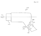
FIG. 10 is a schematic view of a conventional power-feeding connector 100. The power-feeding connector 100 is provided with aconnector body 101 at an end portion thereof and is connected to a power-receiving connector (not shown). An operator connects them with ahandle 103 in the hand. In this process, the operator receives connection resistance F1 (such as insertion friction of a plurality of terminals) occurred between the power-receiving connector and the power-feeding connector, and accordingly the operator needs to push the power-feeding connector with a force F2 that is comparable to the F1. - Furthermore, in the power-
feeding connector 100, thehandle 103 is not formed on an extended line of a central axis of the connector body, and accordingly the force F1 causes a moment M1 at thehandle 103 and an operator needs to cause a moment M2 of the force against the moment M1. In this way, it is difficult for an operator to know how to keep balance of the force that is required for connecting the connectors, and consequently it becomes difficult to connect them in a sensual way. - The present invention was made in view of such problems, and an object of the present invention is to provide a power-feeding connector used for electric vehicles, which does not require a great force but is easily operated at the time of connection.
- In order to achieve the object described above, a first aspect of the present invention provides a power-feeding connector used for an automobile, comprising a connector body, a case that accommodates the connector body therein, a holding member that is attached to the case, and a case-locking mechanism that restricts a movement of the case with respect to the holding member, wherein the connector body and the holding member are slidable in a substantially same axial direction with respect to the case when the case-locking mechanism is unlocked, and the connector body is movable forward with respect to the case with a movement of the holding member when the holding member moves forward with respect to the case in a state where the case-locking mechanism is unlocked.
- It is desirable that insertion detecting means of the power-feeding connector include a pin that is formed slidably in an inserting and removing direction of the case, on a portion of the case which inserts into the power-receiving connector, an elastic member that urges the pin in an inserting direction of the case, and a switch that detects the pin resists the elastic member and is pushed, and the case-locking mechanism is a stopper member that locks the case and the holding member and is actuated by electromagnetic solenoid, and when detecting that the pin touches the power-receiving connector and is pushed inwardly to the case, the switch actuates the electromagnetic solenoid to move the stopper member so that the case-locking mechanism is unlocked.
- It is desirable the insertion detecting means that detect the case is inserted into a power-receiving connector is included in the power-feeding connector, and the insertion detecting means are configured to unlock the case-locking mechanism when detecting that the case is inserted into the power-receiving connector.
- The insertion detecting means may include a slider that is formed slidably in an inserting and removing direction of the case, on a portion of the case which inserts into the power-receiving connector, and an elastic member that urges the slider in an inserting direction of the case, and the case-locking mechanism is a stopper member that locks the case and the holding member, and when the slider touches the power-receiving connector and is pushed inwardly to the case, the stopper member moves so that the case-locking mechanism is unlocked. In this case, a plurality of sliders may be arranged symmetrically with each other against a central axis of the connector body.
- It is desirable that a speed reduction mechanism is provided in the holding member and the holding member and the connector body move with respect to the case via the speed reduction mechanism, and when the holding member moves with respect to the case, a movement distance of the connector body with respect to the case becomes smaller than a movement distance of the holding member with respect to the case.
- That the case may be provided with a hole, and a position of the slider in an inside of the case is viewed through the hole.
- According to the present invention, when a holding member is pushed with respect to a case, a connector body moves in the same direction that of the holding member. With this configuration, it is possible for an operator to recognize movement of the connector body and understand connecting operations sensually, and thereby the procedures for connecting a power-feeding connector to a power-receiving connector can be performed easier.
- Furthermore, because a speed reduction mechanism is provided in the inside of the power-feeding connector so that a movement distance of the connector body is set to be smaller than a movement distance of the holding member, the holding member can be moved with a force smaller than a resistance force that is applied on the connector body at the time of connecting the power-feeding connector and the power-receiving connector. Therefore, the procedures for connecting the connectors can be performed with a smaller force.
- Furthermore, insertion detecting means that detect the case is inserted into the power-receiving connector is provided therein. When the insertion detecting means detect that the case is inserted into the power-receiving connector, a case-locking mechanism is unlocked. Accordingly, even if the case is not completely inserted into the power-receiving connector, movement of the connector can be prevented. For example, when a part of the case contacts a periphery of the power-receiving connector, the connector body would not be moved.
- Therefore, even when the insertion detecting means are combined with the speed reduction mechanism, the effect above can also be obtained because the speed reduction mechanism does not work before the case is not inserted completely into the power-receiving connector.
- The insertion detecting means are configured such that, when a slider that can slide in an inserting and removing direction of the case is urged by an elastic member and the slider touches the power-receiving connector and is pushed inwardly to the case, a stopper member that locks the case and the holding member moves and then the case-locking mechanism is unlocked. With this simple configuration, it is possible to successfully detect that the case is inserted into a charging connector.
- In this case, when a plurality of sliders is arranged symmetrically against a central axis of the connector body, a reaction force is equally applied on a central axis of the case because the sliders are pushed backwardly at positions symmetrical against an inserting axis. Therefore, it is possible to insert the case into the power-receiving connector more accurately.
- Furthermore, when the connector is configured with a hole provided in the case so that the slider in the inside of the case can be viewed, it is possible to recognize whether the slider is successfully pushed. Therefore, it is possible to successfully determine whether the case is inserted into the power-receiving connector accurately.
- Furthermore, a switch and electromagnetic solenoid can be used for the insertion detecting means. With this configuration, it is possible to detect insertion and unlock the case with a smaller force without a mechanism that moves a stopper member by pressing the slider thereon.
- According to the present invention, it is possible to provide a power-feeding connector used for electric vehicles, which does not require a great force but is easily operated at the time of connection.
-
- [
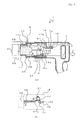
FIG. 1] FIG. 1 illustrates a power-feeding connector 1, and particularlyFIG. 1 (a) is a side view andFIG. 1 (b) is a cross-sectional side view. - [
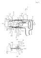
FIG. 2] FIG. 2 illustrates a state where a power-feeding connector 1 is operated, and particularlyFIG. 2 (a) is a side view andFIG. 2 (b) is a cross-sectional side view. - [
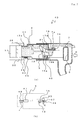
FIG. 3] FIG. 3 illustrates a state where a power-feeding connector 1 and a power-receiving connector 33 are connected with each other, and particularlyFIG. 3 (a) is a cross-sectional side view andFIG. 3 (b) is a bottom perspective view illustrating operations of aslider 25, etc. - [
FIG. 4] FIG. 4 illustrates a state where a power-feeding connector 1 and a power-receiving connector 33 are connected with each other, and particularlyFIG. 4 (a) is a cross-sectional side view andFIG. 4 (b) is a bottom perspective view illustrating operations of aslider 25, etc. - [
FIG. 5] FIG. 5 illustrates a state where a power-feeding connector 1 and a power-receiving connector 33 are connected with each other, and particularlyFIG. 5 (a) is a cross-sectional side view andFIG. 5 (b) is a bottom perspective view illustrating operations of aslider 25, etc. - [
FIG. 6] FIG. 6 is a front view illustrating an example in which a plurality ofsliders 25 is provided. - [
FIG. 7] FIG. 7 illustrates a state where a power-feeding connector 40 and a power-receiving connector 33 are connected with each other, and particularlyFIG. 7 (a) is a cross-sectional side view andFIG. 7 (b) is a bottom perspective view illustrating operations of a switch 41, etc. - [
FIG. 8] FIG. 8 illustrates a state where a power-feeding connector 40 and a power-receiving connector 33 are connected with each other, and particularlyFIG. 8 (a) is a cross-sectional side view andFIG. 8 (b) is a bottom perspective view illustrating operations of a switch 41, etc. - [
FIG. 9] FIG. 9 illustrates a state where a power-feeding connector 40 and a power-receiving connector 33 are connected with each other, and particularlyFIG. 9 (a) is a cross-sectional side view andFIG. 9 (b) is a bottom perspective view illustrating operations of a switch 41, etc. - [
FIG. 10] FIG. 10 illustrates a conventional power-feeding connector 100. Best mode for carrying out the Invention - Hereinafter, an embodiment according to the present invention will be described with reference to the drawings.
FIG. 1 is a schematic view of a power-feedingconnector 1, and particularlyFIG. 1 (a) is a side view andFIG. 1 (b) is a cross-sectional side view. In the present invention, a state illustrated inFIG. 1 is called a normal state. Also, a cable, etc. is not illustrated in the following drawings. The power-feedingconnector 1 mainly includes a holdingmember 3, acase 9, and aconnector body 11. - As illustrated in
FIG. 1 (a) and FIG. 1 (b) , the holdingmember 3 is provided with ahandle 5 at one of the end portions (backward) thereof. Thehandle 5 is a portion to be held in the hand when an operator operates the power-feedingconnector 1. Thehandle 5 is formed such that at least a part of thehandle 5 is set on an extended line of a central axis of the connector body (illustrated as the line T inFIG. 1 (b) , a central axis in a movement direction of theconnector body 11, which is described below). With this configuration, when pushing the holdingmember 3, it is possible to prevent a moment from being generated with a reaction force of interconnection resistance between the connecters, and thereby it becomes easy to operate the power-feeding connector. - The holding
member 3 can accommodates various constituent elements in the inside thereof. Acase 9 is provided at the other end portion (forward) of the holdingmember 3. A portion near a front end portion of the holdingmember 3 is formed in the shape of a cylinder, and a part of the case 9 (a back portion) is accommodated in the inside of the holdingmember 3. The holdingmember 3 can slide back and forth with respect to thecase 9. - The
case 9 is a cylinder-shaped member and accommodates theconnector body 11 in a front end portion thereof. Theconnector body 11 can slide back and forth with respect to thecase 9. On respective portions on which the holdingmember 3 and theconnector body 11 slide with respect to thecase 9, a guiding mechanism (not shown) and a stopper for restricting the sliding range may be arranged. - The
case 9 is provided with anarm 13 in the inside thereof. A portion near one of the end portions of thearm 13 is rotatably attached to thecase 9 by a pin 23a. A portion near the other end portion of thearm 13 is coupled, by a connecting part 15a, to aconnector bar 16 that is joined with the holdingmember 3. Thearm 13 includes a long hole formed therein and theconnector bar 16 includes a pin, etc. formed thereon so that thearm 13 and theconnector bar 16 are rotatably connected by the connecting part 15a. - A substantially central portion (a portion between the pin 23a and the connecting part 15a) of the
arm 13 is connected to theconnector body 11 by the connecting part 15b. The connecting part 15b is configured in the same manner as the connecting part 15a. Therefore, when thearm 13 rotates, theconnector body 11 and the holdingmember 3 can move in the straight line with respect to thecase 9 in connection with rotary of thearm 13. - The
case 9 is provided with a lockingmember 17 formed in the inside thereof. The lockingmember 17 is rotatably attached to thecase 9 by a pin 23b. A locking pin 17a is formed on an end portion at a front side of the lockingmember 17 so as to be faced upwardly. The locking pin 17a is placed on a position of a hole that is formed in thecase 9. - An engaging part 17b is formed on an end portion at a back side of the locking
member 17 so as to be faced downwardly. The engaging part 17b is formed convexly so that the engaging part 17b and anengaging part 21 can be engaged with each other. The engagingpart 21 is fixed on the part of holdingmember 3. In the normal state, the engagingparts 17b and 21 are not engaged with each other but a projection of the engaging part 17b is set on a projection of theengaging part 21. Furthermore, in the normal state, the engaging part 17b is pushed upwardly by the engagingpart 21, and accordingly the locking pin 17a does not project from the case 9 (the hole formed in the case 9) and remains within thecase 9 via the pin 23b. - The holding
member 3 is provided with anoperating part 7 in the inside thereof. The operatingpart 7 is rotatably attached to the holdingmember 3 by a pin 23c. An end portion at a back side of the operatingpart 7 projects from the holdingmember 3 toward an outside so that an operator can operate theoperating part 7 from the outside. A locking pin 7a is formed at a front side of the operatingpart 7 so as to be faced downwardly. The locking pin 7a touches a part of thecase 9, and thus the locking pin 7a is pushed upwardly by the part of thecase 9 in the normal state. Aconcave part 19 that enables the locking pin 7a to be engaged therewith is provided at a front side of a portion, which touches the locking pin 7a in the normal state, of thecase 9. - The
case 9 is provided with aslider 25 in the inside thereof. One of the end portions of theslider 25 projects forward from thecase 9. That is, a step is formed in front of thecase 9 and theslider 25 is exposed on the step. Theslider 25 can slide in an axial direction (in a movement direction of thecase 9 as well as an inserting and removing direction of the connector). - A
hole 24 is formed at a part of thecase 9. A position of theslider 25 in the inside of thecase 9 can be viewed through thehole 24. The arrangement of theslider 25 and thehole 24 is not limited to the example illustrated in the drawings, however, they can be suitably arranged. For example, thehole 24 may be arranged on a top surface or a side surface of thecase 9 and theslider 25 may be arranged on a top portion or a side surface of the power-feeding connector in order to make them easier to be visually recognized. - A
stopper member 27 is provided near a front end portion of theconnector bar 16, at the back of theslider 25. Thestopper member 27 touches theslider 25 and is configured to be movable in response to movement of theslider 25. Thestopper member 27 locks thecase 9 and the holdingmember 3. That is, thestopper member 27 functions as a case-locking mechanism to prevent thecase 9 from moving with respect to the holdingmember 3. The details of mechanisms and operations of theslider 25 that serves as insertion detecting means and thestopper member 27 that serves as the case-locking mechanism will be described later. - Next, a state where the power-feeding
connector 1 is operated is described hereinafter.FIG. 2 illustrates the power-feedingconnector 1 in which the holding member is moved, and particularlyFIG. 2 (a) is a side view andFIG. 2 (b) is a cross-sectional side view. - As described above, in the normal state, the holding
member 3 is locked by thecase 9 and thestopper member 27. When theslider 25 is pushed inwardly (in a direction of the arrow A inFIG. 2 (b) ) from the normal state, thestopper member 27 is pushed and moved by theslider 25. In this process, the holdingmember 3 and thecase 9 are unlocked by the movement of thestopper member 27. - In a state where the holding
member 3 and thecase 9 are unlocked, when the holdingmember 3 is moved forward with respect to the case 9 (in a direction of the arrow C inFIG. 2 (b) ), the connecting part 15a that is coupled with the holding member 3 (the connector bar 16) is pushed forward. The connecting part 15a moves forward, and accordingly thearm 13 rotates on the pin 23a that serves as a rotation axis (in a direction of the arrow D inFIG. 2 (b) ). When thearm 13 rotates, theconnector body 11 that is coupled with thearm 13 by the connecting part 15b moves in the same direction as that of the holding member 3 (in a direction of the arrow E inFIG. 2 (b) ). - Because the position where the holding
member 3 couples with thearm 13 is different from the position where theconnector body 11 couples with thearm 13, a movement distance of the holdingmember 3 with respect to thecase 9 and that of theconnector body 11 with respect to thecase 9 differ with each other. Specifically, in the case where the ratio of distances from the pin 23a to the connecting part 15a and to the connecting part 15b is 2:1, if the movement distance of the holdingmember 3 with respect to thecase 9 is set to be 2, theconnector body 11 moves a distance of 1. That is, the mechanism such as thearm 13 functions as a speed reduction mechanism. - Furthermore, when the holding
member 3 moves forward with respect to thecase 9, the engaging part 17b and theengaging part 21 are engaged with each other. Consequently, the lockingmember 17 rotates on the pin 23b that serves as a rotation axis. In other words, when the engaging part 17b that is one of the sides of the lockingmember 17 is pushed downwardly, the lockingmember 17 rotates and then the locking pin 17a that is the other side of the lockingmember 17 is pushed upwardly. Thereby, the locking pin 17a projects through the hole toward the outside of the case 9 (in a direction of the arrow G inFIG. 2 (b) ). The lockingmember 17 may be configured with a spring, etc. so as to always resume the state illustrated inFIG. 2 (the state where the engaging part 17b is pushed downwardly). - Furthermore, when the holding
member 3 moves forward with respect to thecase 9, the locking pin 7a of the operatingpart 7 moves toward a direction of theconcave part 19 and then the locking pin 7a is engaged with theconcave part 19. Consequently, the operatingpart 7 rotates on the pin 23c that serves as a rotation axis. In other words, when the locking pin 7a is pushed downwardly, the operatingpart 7 rotates and then the other end portion of the operatingpart 7 is pushed upwardly (in a direction of the arrow F inFIG. 2 (b) ). The operatingpart 7 may be configured with a spring, etc. so as to always resume the state illustrated inFIG. 2 (the state where the locking pin 7a is pushed downwardly). - When the locking pin 7a engages with the
concave part 19, movement of the holdingmember 3 with respect to thecase 9 is locked. That is, the operatingpart 7 functions as locking means to prevent the holding member 3 (and the connector body 11) from moving with respect to thecase 9. Furthermore, the operatingpart 7 functions as an unlocking mechanism to unlock the locked state by being operated (the outer end portion of the operatingpart 7 is pushed downwardly). With the configuration above, a connection state of the connector can be successfully maintained as well as it can be easily unlocked. - A display part that displays a position of the operating
part 7 may be provided on an upper portion of thehandle 5. For example, the operatingpart 7 is in a state where a side of the locking pin 7a thereof is pushed upwardly in the normal state illustrated inFIG. 1 . Accordingly, in the state above, the operatingpart 7 rotates in a right-handed direction ofFIG. 1 on the pin 23c that serves as an axis. On the other hand, in the state illustrated inFIG. 2 , a side of the locking pin 7a of the operatingpart 7 is pushed downwardly. Accordingly, the operatingpart 7 rotates in a left-handed direction ofFIG. 2 on the pin 23c that serves as an axis. - Here, a hole is provided as the display part on a part of the holding
member 3 so that a state of the operatingpart 7 can be recognized through the display part. With this configuration, whether the power-feedingconnector 1 is in a locked state (the state illustrated inFIG. 2 ) or in an unlocked state (the normal state) can be easily viewed. Other methods for viewing a state of the operatingpart 7 and other arrangements of the display part may be applied herein. - Furthermore, a parallel linkage may be used in a portion where the holding member 3 (or the connector body 11) slides on the
case 9. By using the parallel linkage, the backlash hardly occurs when the holding member 3 (or the connector body 11) slides on thecase 9, and it is possible to restrict a movement range therebetween. - Next, a method for using the power-feeding
connector 1 will be described hereinafter.FIG. 3 to FIG. 5 illustrate processes of connecting the power-feedingconnector 1 and a power-receivingconnector 33, and particularlyFIG. 3 (a) toFIG. 5 (a) are cross-sectional side views andFIG. 3 (b) toFIG. 5 (b) are bottom perspective views illustrating operations of theslider 25, etc. - First, as illustrated in
FIG. 3 (a) , the power-feedingconnector 1 in the normal state is set to face to the power-receivingconnector 33 that is to be connected. Specifically, a front end of thecase 9 is inserted into a concave part of the power-receiving connector. Here, the power-receivingconnector 33 accommodates aconnector body 37 in the inside thereof. In the state above, there is a space between theconnector bodies connector body 11 and a male terminal of theconnector body 37 are not connected with each other. - Accordingly, as illustrated in
FIG. 3 (b) , a front end of theslider 25 does not touch the power-receivingconnector 33 but projects forward from thecase 9. Theslider 25 is always urged forward (in a direction of the arrow H inFIG. 3 (b) ) by anelastic member 29 that is provided in the inside of thecase 9. That is, theslider 25 always projects forward whenever the power-feedingconnector 1 is in the normal state. - The
stopper member 27 is provided on a back end of theslider 25, in the inside of thecase 9. Thestopper member 27 is pressed in a direction of the connector bar 16 (that is, in a direction perpendicular to a sliding direction of the slider 25) by an elastic member 31 (in a direction of the arrow I inFIG. 3 (b) ). As illustrated inFIG. 3 (b) , for example, a side surface of thestopper member 27 touches apin 32 of theconnector bar 16. Accordingly, thestopper member 27 prevents theconnector bar 16 from moving further forward, and thereby the movement of the holdingmember 3, on which theconnector bar 16 is fixed, with respect to thecase 9 is restricted and the holdingmember 3 is stopped. - For example, even when the
case 9 is inserted diagonally into the power-receivingconnector 33 or even when thecase 9 touches a periphery part of the power-receivingconnector 33, theslider 25 and thestopper member 27 prevent the holdingmember 3 from moving forward with respect to thecase 9. That is, in the case where thestopper member 27 that serves as the case-locking mechanism is in a locked state, even if the holdingmember 3 is inserted, thecase 9 is not pushed inwardly to the holdingmember 3. - A part of the
slider 25 can be viewed through thehole 24. That is, in a state where theslider 25 projects forward, by marking or coloring a position that corresponds to a position of thehole 24, it is possible to visually recognize through thehole 24 that theslider 25 projects forward. - Furthermore, a
concave part 35 is formed at a position of an inner surface of the power-receivingconnector 33, which corresponds to a position of the locking pin 17a in a state where thecase 9 is arranged on the part of the power-receivingconnector 33. In order to position the locking pin 17a with theconcave part 35 or position the female terminal with the male terminal described above, a guide, etc. for positioning thecase 9 with the power-receivingconnector 33 may be formed on an outer surface of thecase 9. - Secondly, as illustrated in
FIG. 4 , when the holding member of the power-feedingconnector 1 is pushed to a side of the power-receiving connector 33 (in a direction of the arrow C inFIG. 4 (a) ), the step of thecase 9 contacts the periphery part of the power-receivingconnector 33. Theslider 25 projects on the step of thecase 9, and accordingly theslider 25 touches the periphery part of the power-receivingconnector 33. - Therefore, as illustrated in
FIG. 4 (b) , theslider 25 is pushed backwardly (toward the inside of thecase 9, in a direction of the arrow A inFIG. 4 (b) ) while resisting to a forward pressing force by theelastic member 29. The back end of theslider 25 touches thestopper member 27. A taper part 27a is formed on a surface where thestopper member 27 touches theslider 25. - Accordingly, when the
slider 25 moves backwardly (in the direction of the arrow A inFIG. 4 (b) ), the back end of theslider 25 slides on the taper part 27a and then a movement direction of thestopper member 27 is changed. That is, thestopper member 27 moves substantially perpendicular to the sliding direction of the slider 25 (in a direction of the arrow B inFIG. 4 (b) ) while resisting to a pressing force by theelastic member 31. Thestopper member 27 moves away from thepin 32, and thereby thestopper member 27 and the pin 32 (the connector bar 16) that have been engaged with each other are unlocked. - The insertion detecting means for detecting whether the
case 9 is inserted into the power-receivingconnector 33 are not limited to theslider 25 illustrated in the drawings, however, any mechanisms may be applied as long as they work when thecase 9 is inserted. Furthermore, a mechanism for unlocking the case-locking mechanism at the time of detection by the insertion detecting means needs not necessarily be thestopper member 27 illustrated in the drawings, however, any mechanisms may be applied as long as they can unlock the engaged state in response to results detected by the insertion detecting means. - As described above, the state where the
case 9 and the holdingmember 3 are engaged with each other is unlocked by inserting thecase 9 into the power-receivingconnector 33 completely, which makes it possible to allow thecase 9 and the holdingmember 3 to move freely. A part of theslider 25 can be viewed through thehole 24. That is, in a state where theslider 25 is pushed backwardly, by marking or coloring a position that corresponds to a position of thehole 24, it is possible to visually recognize through thehole 24 that theslider 25 is pushed backwardly. In this way, it is possible to visually recognize that thecase 9 is successfully inserted into the power-receivingconnector 33. - Thirdly, as illustrated in
FIG. 5 , the holdingmember 3 of the power-feedingconnector 1 is further pushed to the side of the power-receiving connector 33 (in a direction of the arrow C inFIG. 5 (a) ). The holdingmember 3 cannot be pushed any further because thecase 9 touches the power-receivingconnector 33. On the other hand, the state where the holdingmember 3 is stopped with respect to thecase 9 is unlocked. Accordingly, as illustrated inFIG. 5 (b) , thepin 32 does not touch thestopper member 27. Theconnector bar 16 does not touch thestopper member 27, and thus moves forward (in a direction of the arrow C inFIG. 5 (b) ). - In this way, it is possible to move the holding
member 3 forward with respect to thecase 9. In this process, theconnector body 11 moves forward (in a direction of the arrow E inFIG. 5 ) with respect to thecase 9 with the movement of the holdingmember 3. Theconnector body 11 projects from a front portion of thecase 9, and accordingly it is connected to theconnector body 37 of the power-receiving connector. - Here, in the case where the ratio of movement distances from the holding
member 3 to thecase 9 and from theconnector body 11 to thecase 9 is set to be 2:1, the holding member is pushed from a distance twice as far as a space length for connection between theconnector bodies connector body 11 can move a distance enough for the connectors to be connected. In other word, the connectors can be connected by pushing the holdingmember 3 with half force of force for connecting the connectors (that is resisting force for connection). The speed reducing ratio of the speed reduction mechanism is set arbitrarily considering resisting force for connection or user-friendliness. - In a state illustrated in
FIG. 5 (a) , as described above, the locking pin 17a is engaged with theconcave part 35. Consequently, the power-receivingconnector 33 and the power-feedingconnector 1 are locked in a state where they are connected with each other. Furthermore, the locking pin 7a formed at an end portion of the operatingpart 7 is engaged with theconcave part 19, and thereby the holdingmember 3 is locked so that it does not move with respect to thecase 9. Therefore, even when a cable, etc. (not shown) is pulled, the power-feedingconnector 1 is not easily disconnected from the power-receivingconnector 33. - In order to disconnect the power-feeding
connector 1, it is necessary to unlock the engaged locking pin 17a by the process in which the holdingmember 3 is pulled back in a state where the locking pin 7a is pushed upwardly by pushing the end portion of the operatingpart 7 so that the engaging part 17b moves onto the engagingpart 21. By this process, the power-feedingconnector 1 can be easily disconnected. - In the example described above, a pair of the
slider 25 and thestopper member 27 is arranged therein, however, the present invention is not limited to this arrangement. For example, as illustrated inFIG. 6 , a plurality of the sliders 25 (and thecorresponding stopper members 27, etc.) may be arranged therein. - When a plurality of the
sliders 25 is arranged therein, they are desired to be arranged at point symmetrical positions relative to aconnector center 39 that is a center of the connector body 11 (the case 9) in a front view of theconnector body 11. With this configuration, it is possible to insert thecase 9 into the power-receivingconnector 33 accurately because a pushing force of thesliders 25 is applied equally on theconnector center 39. - As described above, the power-feeding
connector 1 according to this embodiment does not require a great force and is easily connected to a power-receiving connector. Especially by using the power-feedingconnector 1, an operator is able to understand connecting procedures easily and sensually because a direction to which an operator pushes the holding member is the same as a connecting direction of theconnector body 11. - Furthermore, the case-locking mechanism that locks the
case 9 and the holdingmember 3 is provided therein, and accordingly the holdingmember 3 does not move with respect to thecase 9 in the normal state. In this way, the holdingmember 3 does not move with respect to thecase 9 in a state where thecase 9 is not completely inserted into the power-receivingconnector 33. - Furthermore, because the speed reduction mechanism is provided for the movement of the holding
member 3 and theconnector body 11 with respect to thecase 9, the force required to connect the connectors with each other can be reduced. Still further, when the speed reduction mechanism is used with the case-locking mechanism described above, the speed reduction mechanism does not work before inserting thecase 9 into the power-receivingconnector 33 but works after thecase 9 is completely inserted into the power-receiving connector in order to connect the connectors with each other. - Furthermore, because the
slider 25 is used as the insertion detecting means, it is possible to successfully detect that thecase 9 is inserted into the power-receivingconnector 33 with a simple configuration. Still further, because a position of theslider 25 can be viewed through thehole 24 that is formed in thecase 9, it is possible to visually recognize whether theslider 25 is successfully pushed. That is, it is able to visually recognize whether thecase 9 is completely inserted into the power-receivingconnector 33. - Next, a second embodiment according to the present invention will be described below.
FIG. 7 to FIG. 9 illustrate processes for connecting a power-feedingconnector 40 according to the second embodiment to the power-receivingconnector 33, and particularlyFIG. 7(a) to FIG. 9 (a) are cross-sectional side views andFIG. 7 (b) toFIG. 9 (b) are bottom perspective views illustrating operations of a switch, etc. In the second embodiment, the same numerals as those ofFIG. 1 to FIG. 5 are allotted to configurations having the same functions as those illustrated inFIG. 1 to FIG. 5 , and the overlapping explanations will be omitted. - The power-feeding
connector 40 is configured in substantially the same manner as the power-feedingconnector 1, however, there are differences in the insertion detecting means and the case-locking mechanism. The power-feedingconnector 40 includes a switch 41 and astopper member 45, etc. instead of theslider 25 and thestopper member 27, etc. - As illustrated in
FIG. 7 (b) , the switch 41 as an insertion detecting part is provided at the step of thecase 9. The switch 41 is provided with apin 43 that can slide in an axial direction (a movement direction of thecase 9 as well as an inserting and removing direction of the connector). An end of thepin 43 projects forward and is pushed from the front portion of the case 9 (in a direction of the arrow J inFIG. 7 (b) ). The switch 41 is a known switch such as a limit switch and a proximity switch, and any switches may be applied as long as the switch can detect that thepin 43 is pushed into a body of the switch 41. - A
hole 49 is provided in theconnector bar 16. Thestopper member 45 is arranged toward a direction vertical to the axial direction (the movement direction of thecase 9 as well as the inserting and removing direction of the connector) at a position to which thehole 49 corresponds in the normal state, in the inside of thecase 9. Thestopper member 45 can be actuated by electromagnetic solenoid, etc to operate thepin 47. That is, by operating thestopper member 45, it is possible to insert and remove thepin 47 with respect to thehole 49. - In the normal state, that is, in the case where the
pin 43 of the switch 41 is pushed forward, thepin 47 of thestopper member 45 is maintained with being inserted into the hole 49 (in a direction of the arrow K inFIG. 7 (b) ). In this state, because thepin 47 is inserted into thehole 49, theconnector bar 16 is stopped by thestopper member 45. Accordingly, the holdingmember 3 cannot move with respect to thecase 9. - Secondly, as illustrated in
FIG. 8 , when the holdingmember 3 of the power-feedingconnector 40 is pushed toward the side of the power-receiving connector 33 (in a direction of the arrow C inFIG. 7 (a) ), the step of thecase 9 contacts the periphery part of the power-receivingconnector 33. Thepin 43 projects on the step of thecase 9, and accordingly thepin 43 contacts the periphery part of the power-receivingconnector 33. - Therefore, as illustrated in
FIG. 8 (b) , thepin 43 is pushed backwardly (into the inside of a body of the switch 41, in a direction of the arrow L inFIG. 8 (b) ). When thepin 43 is pushed backwardly, the switch 41 actuates thestopper member 45 and then thepin 47 is removed from the hole 49 (in a direction of the arrow M inFIG. 8 (b) ). Accordingly, the state where theconnector bar 16 is stopped by thestopper member 45 is unlocked. - Thirdly, as illustrated in
FIG. 9 , the holdingmember 3 of the power-feedingconnector 40 is further pushed to the side of the power-receiving connector 33 (in a direction of the arrow C inFIG. 9 (a) ). As described above, the holdingmember 3 cannot be pushed any further because thecase 9 touches the power-receivingconnector 33. On the other hand, the state where the holdingmember 3 is stopped with respect to thecase 9 is unlocked. That is, as illustrated inFIG. 9 (b) , theconnector bar 16 does not touch the stopper member 45 (the pin 47), and thus theconnector bar 16 moves forward (in a direction of the arrow C inFIG. 9 (a) ). - In this way, it is possible to move the holding
member 3 forward with respect to thecase 9. In this process, theconnector body 11 moves forward (in a direction of the arrow E inFIG. 9 (a) ) with respect to thecase 9 with the movement of the holdingmember 3. Theconnector body 11 projects from the front portion of thecase 9, and accordingly it is connected to theconnector body 37 of the power-receiving connector. - According to the power-feeding
connector 40 of the second embodiment, it is possible to obtain the same effect as that of the power-feedingconnector 1. Furthermore, only a small force is required at the time of inserting the connector because thestopper member 45 is actuated by an electrical signal from the switch that is used as the insertion detecting means. - The embodiments are described above with reference to the attached drawings, however, the technical scope of the present invention is not limited by the embodiments above. It is obvious that a person skilled in the art can easily make the various examples of change or modifications within the category of the technical idea described in the claim, and moreover, it is understood that such examples naturally belong to the technical scope of the present invention.
- For example, the shape of the holding
member 3 and the arrangement of each constituent elements in the inside of thecase 9 and the shape thereof are not limited to the examples illustrated in the drawings. -
- 1, 40
- power-feeding connector
- 3
- holding member
- 5
- handle
- 7
- operating part
- 7a
- locking pin
- 9
- case
- 11
- connector body
- 13
- arm
- 15a, 15b
- connecting part
- 16
- connector bar
- 17
- locking member
- 17a
- locking pin
- 17b
- engaging part
- 19
- concave part
- 21
- engaging part
- 23a, 23b, 23c
- pin
- 24
- hole
- 25
- slider
- 27, 45
- stopper member
- 27a
- taper part
- 29
- elastic member
- 31
- elastic member
- 32
- pin
- 33
- power-receiving connector
- 35
- concave part
- 37
- connector body
- 39
- connector center
- 41
- switch
- 43
- pin
- 47
- pin
- 49
- hole
- 100
- power-feeding connector
- 101
- connector body
- 103
- handle
Claims (7)
- A power feed connector used for an automobile, comprising:a connector body;a case that accommodates the connector body therein;a holding member that is attached to the case; anda case-locking mechanism that restricts a movement of the case with respect to the holding member, whereinthe connector body and the holding member are slidable in a substantially same axial direction with respect to the case when the case-locking mechanism is unlocked, andthe connector body is movable forward with respect to the case with a movement of the holding member when the holding member moves forward with respect to the case in a state where the case-locking mechanism is unlocked.
- The power feed connector according to claim 1, wherein
a speed reduction mechanism is provided in the holding member and the holding member and the connector body move with respect to the case via the speed reduction mechanism, and
when the holding member moves with respect to the case, a movement distance of the connector body with respect to the case becomes smaller than a movement distance of the holding member with respect to the case. - The power feed connector according to claim 1, further comprising insertion detecting means that detect the case is inserted into a power-receiving connector, wherein
the insertion detecting means are configured to unlock the case-locking mechanism when detecting that the case is inserted into the power-receiving connector. - The power feed connector according to claim 3, wherein
the insertion detecting means include
a slider that is formed slidably in an inserting and removing direction of the case, on a portion of the case which inserts into the power-receiving connector, and
an elastic member that urges the slider in an inserting direction of the case,
the case-locking mechanism is a stopper member that locks the case and the holding member, and
when the slider touches the power-receiving connector and is pushed inwardly to the case, the stopper member moves so that the case-locking mechanism is unlocked. - The power feed connector according to claim 4, wherein a plurality of sliders is arranged symmetrically with each other against a central axis of the connector body.
- The power feed connector according to claim 4, wherein the case is provided with a hole, and a position of the slider in an inside of the case is viewed through the hole.
- The power feed connector according to claim 3, wherein
the insertion detecting means include
a pin that is formed slidably in an inserting and removing direction of the case, on a portion of the case which inserts into the power-receiving connector,
an elastic member that urges the pin in an inserting direction of the case, and
a switch that detects the pin resists the elastic member and is pushed,
the case-locking mechanism is a stopper member that locks the case and the holding member and is actuated by electromagnetic solenoid, and
when detecting that the pin touches the power-receiving connector and is pushed inwardly to the case, the switch actuates the electromagnetic solenoid to move the stopper member so that the case-locking mechanism is unlocked.
Applications Claiming Priority (2)
| Application Number | Priority Date | Filing Date | Title |
|---|---|---|---|
| JP2011233563A JP5503619B2 (en) | 2011-10-25 | 2011-10-25 | Power supply connector |
| PCT/JP2012/076404 WO2013061801A1 (en) | 2011-10-25 | 2012-10-12 | Power feed connector |
Publications (3)
| Publication Number | Publication Date |
|---|---|
| EP2772992A1 true EP2772992A1 (en) | 2014-09-03 |
| EP2772992A4 EP2772992A4 (en) | 2015-06-17 |
| EP2772992B1 EP2772992B1 (en) | 2020-04-15 |
Family
ID=48167634
Family Applications (1)
| Application Number | Title | Priority Date | Filing Date |
|---|---|---|---|
| EP12843832.2A Active EP2772992B1 (en) | 2011-10-25 | 2012-10-12 | Power feed connector |
Country Status (5)
| Country | Link |
|---|---|
| US (1) | US9088096B2 (en) |
| EP (1) | EP2772992B1 (en) |
| JP (1) | JP5503619B2 (en) |
| CN (1) | CN103348543B (en) |
| WO (1) | WO2013061801A1 (en) |
Cited By (3)
| Publication number | Priority date | Publication date | Assignee | Title |
|---|---|---|---|---|
| EP2894726A4 (en) * | 2012-09-03 | 2016-04-20 | Furukawa Electric Co Ltd | Power supply connector |
| CN109565133A (en) * | 2016-08-16 | 2019-04-02 | 国际商业机器公司 | Power distribution unit |
| EP2806511B1 (en) * | 2012-01-16 | 2019-05-15 | Nissan Motor Company, Limited | Power-feeding connector |
Families Citing this family (13)
| Publication number | Priority date | Publication date | Assignee | Title |
|---|---|---|---|---|
| CN104756328A (en) * | 2012-10-22 | 2015-07-01 | 古河电气工业株式会社 | Power supply connector |
| JP5718302B2 (en) * | 2012-11-19 | 2015-05-13 | 古河電気工業株式会社 | Power supply connector |
| JP5922565B2 (en) * | 2012-12-13 | 2016-05-24 | 株式会社東海理化電機製作所 | Locking device |
| JP5902602B2 (en) * | 2012-12-13 | 2016-04-13 | 株式会社東海理化電機製作所 | Locking device |
| EP2849291B1 (en) * | 2013-09-16 | 2017-04-05 | Intercontec Pfeiffer Industrie-Steckverbindungen GmbH | Plug-in connection system with a socket and a plug |
| JP5690914B1 (en) * | 2013-12-16 | 2015-03-25 | 株式会社フジクラ | Power supply connector |
| JP6009528B2 (en) * | 2014-12-18 | 2016-10-19 | 住友電装株式会社 | Charging inlet |
| CN104916972A (en) * | 2015-07-13 | 2015-09-16 | 沈素春 | Power supply device with moving roller |
| JP6537938B2 (en) | 2015-09-02 | 2019-07-03 | 日本航空電子工業株式会社 | Connector and connector assembly |
| DE102017119056B4 (en) * | 2017-08-21 | 2022-05-19 | HARTING Automotive GmbH | Charging connector with actuation means |
| JP7052943B2 (en) * | 2018-02-16 | 2022-04-12 | 住友電工デバイス・イノベーション株式会社 | Optical transceiver |
| CN110953503B (en) * | 2019-11-11 | 2021-07-16 | 朱辰 | Square lamp |
| CN114987236A (en) * | 2022-05-30 | 2022-09-02 | 安徽顺信线缆有限公司 | An intelligent new energy vehicle charging line device |
Family Cites Families (16)
| Publication number | Priority date | Publication date | Assignee | Title |
|---|---|---|---|---|
| JP3042816B2 (en) * | 1992-12-18 | 2000-05-22 | 矢崎総業株式会社 | Power supply connector |
| JP2978348B2 (en) | 1992-12-18 | 1999-11-15 | 矢崎総業株式会社 | Power supply connector |
| US5429524A (en) * | 1993-04-16 | 1995-07-04 | Sumitomo Wiring Systems, Ltd. | Coupling device of charging connector assembly for electric car |
| JP2916348B2 (en) * | 1993-07-22 | 1999-07-05 | 住友電装株式会社 | Electric vehicle charging connector |
| JP3433432B2 (en) * | 1993-12-28 | 2003-08-04 | 矢崎総業株式会社 | Power supply connector |
| JP3463820B2 (en) * | 1994-04-01 | 2003-11-05 | 矢崎総業株式会社 | Power supply connector |
| JP3109712B2 (en) * | 1994-12-01 | 2000-11-20 | 矢崎総業株式会社 | Power supply connector |
| JP3292278B2 (en) * | 1995-12-06 | 2002-06-17 | 矢崎総業株式会社 | Electric vehicle charging connector |
| JP3262203B2 (en) * | 1996-02-16 | 2002-03-04 | 矢崎総業株式会社 | Low insertion / extraction force connector |
| JP3731797B2 (en) | 1999-11-08 | 2006-01-05 | 矢崎総業株式会社 | Power supply connector |
| JP3866052B2 (en) * | 2001-05-24 | 2007-01-10 | 矢崎総業株式会社 | Power supply connector |
| CN201289909Y (en) * | 2008-11-03 | 2009-08-12 | 珠海格力电器股份有限公司 | Quick power supply device for air conditioner |
| WO2011081124A1 (en) * | 2009-12-28 | 2011-07-07 | 株式会社フジクラ | Power-feed connector |
| JP5393440B2 (en) * | 2009-12-28 | 2014-01-22 | 株式会社フジクラ | Power supply connector |
| JP5482295B2 (en) * | 2010-03-01 | 2014-05-07 | 住友電装株式会社 | Charging connector |
| JP5697031B2 (en) * | 2011-02-24 | 2015-04-08 | 古河電気工業株式会社 | Power supply connector |
-
2011
- 2011-10-25 JP JP2011233563A patent/JP5503619B2/en active Active
-
2012
- 2012-10-12 WO PCT/JP2012/076404 patent/WO2013061801A1/en not_active Ceased
- 2012-10-12 EP EP12843832.2A patent/EP2772992B1/en active Active
- 2012-10-12 CN CN201280007696.XA patent/CN103348543B/en not_active Expired - Fee Related
-
2013
- 2013-10-22 US US14/059,884 patent/US9088096B2/en not_active Expired - Fee Related
Cited By (4)
| Publication number | Priority date | Publication date | Assignee | Title |
|---|---|---|---|---|
| EP2806511B1 (en) * | 2012-01-16 | 2019-05-15 | Nissan Motor Company, Limited | Power-feeding connector |
| EP2894726A4 (en) * | 2012-09-03 | 2016-04-20 | Furukawa Electric Co Ltd | Power supply connector |
| CN109565133A (en) * | 2016-08-16 | 2019-04-02 | 国际商业机器公司 | Power distribution unit |
| CN109565133B (en) * | 2016-08-16 | 2020-04-24 | 国际商业机器公司 | Power distribution unit |
Also Published As
| Publication number | Publication date |
|---|---|
| JP5503619B2 (en) | 2014-05-28 |
| US20140045360A1 (en) | 2014-02-13 |
| CN103348543A (en) | 2013-10-09 |
| EP2772992B1 (en) | 2020-04-15 |
| WO2013061801A1 (en) | 2013-05-02 |
| US9088096B2 (en) | 2015-07-21 |
| CN103348543B (en) | 2016-05-18 |
| EP2772992A4 (en) | 2015-06-17 |
| JP2013093149A (en) | 2013-05-16 |
Similar Documents
| Publication | Publication Date | Title |
|---|---|---|
| US9088096B2 (en) | Power feed connector | |
| CN103748746B (en) | power supply connector | |
| EP2843773B1 (en) | Connector device | |
| CN103907245B (en) | power supply connector | |
| JP5972391B2 (en) | Power supply connector and unlocking method of power supply connector | |
| CN101226833B (en) | Power supply circuit connector and method of connecting power supply circuit | |
| EP2308140B1 (en) | Electrical connector system, an electrical device comprising the same and a method for unmating the same | |
| EP2863488A1 (en) | Connector | |
| CN104025388B (en) | Electric connector | |
| JP5697031B2 (en) | Power supply connector | |
| EP2705975A1 (en) | Vehicle charging device | |
| EP0762554A1 (en) | Locking device for connectors and use thereof for charging connectors and/or high-voltage connectors | |
| EP2811586A1 (en) | Connector device | |
| JPH07111172A (en) | Electric vehicle charging connector | |
| CN104756328A (en) | Power supply connector | |
| CN216214505U (en) | Secondary locking mechanism and secondary locking connector | |
| JP2014107200A (en) | Power supply connector | |
| JPH0765900A (en) | Electric vehicle charging connector | |
| JP2015072851A (en) | Connector | |
| JP5718302B2 (en) | Power supply connector | |
| EP3960970B1 (en) | Locking device |
Legal Events
| Date | Code | Title | Description |
|---|---|---|---|
| PUAI | Public reference made under article 153(3) epc to a published international application that has entered the european phase |
Free format text: ORIGINAL CODE: 0009012 |
|
| 17P | Request for examination filed |
Effective date: 20140325 |
|
| AK | Designated contracting states |
Kind code of ref document: A1 Designated state(s): AL AT BE BG CH CY CZ DE DK EE ES FI FR GB GR HR HU IE IS IT LI LT LU LV MC MK MT NL NO PL PT RO RS SE SI SK SM TR |
|
| DAX | Request for extension of the european patent (deleted) | ||
| RA4 | Supplementary search report drawn up and despatched (corrected) |
Effective date: 20150520 |
|
| RIC1 | Information provided on ipc code assigned before grant |
Ipc: H01R 13/641 20060101ALI20150513BHEP Ipc: H01R 13/627 20060101ALI20150513BHEP Ipc: H01R 13/639 20060101AFI20150513BHEP |
|
| 17Q | First examination report despatched |
Effective date: 20160316 |
|
| STAA | Information on the status of an ep patent application or granted ep patent |
Free format text: STATUS: EXAMINATION IS IN PROGRESS |
|
| GRAP | Despatch of communication of intention to grant a patent |
Free format text: ORIGINAL CODE: EPIDOSNIGR1 |
|
| STAA | Information on the status of an ep patent application or granted ep patent |
Free format text: STATUS: GRANT OF PATENT IS INTENDED |
|
| INTG | Intention to grant announced |
Effective date: 20191202 |
|
| GRAS | Grant fee paid |
Free format text: ORIGINAL CODE: EPIDOSNIGR3 |
|
| GRAA | (expected) grant |
Free format text: ORIGINAL CODE: 0009210 |
|
| STAA | Information on the status of an ep patent application or granted ep patent |
Free format text: STATUS: THE PATENT HAS BEEN GRANTED |
|
| AK | Designated contracting states |
Kind code of ref document: B1 Designated state(s): AL AT BE BG CH CY CZ DE DK EE ES FI FR GB GR HR HU IE IS IT LI LT LU LV MC MK MT NL NO PL PT RO RS SE SI SK SM TR |
|
| REG | Reference to a national code |
Ref country code: CH Ref legal event code: EP Ref country code: GB Ref legal event code: FG4D |
|
| REG | Reference to a national code |
Ref country code: DE Ref legal event code: R096 Ref document number: 602012069353 Country of ref document: DE |
|
| REG | Reference to a national code |
Ref country code: IE Ref legal event code: FG4D |
|
| REG | Reference to a national code |
Ref country code: AT Ref legal event code: REF Ref document number: 1258391 Country of ref document: AT Kind code of ref document: T Effective date: 20200515 |
|
| REG | Reference to a national code |
Ref country code: SE Ref legal event code: TRGR |
|
| REG | Reference to a national code |
Ref country code: NL Ref legal event code: MP Effective date: 20200415 |
|
| REG | Reference to a national code |
Ref country code: LT Ref legal event code: MG4D |
|
| PG25 | Lapsed in a contracting state [announced via postgrant information from national office to epo] |
Ref country code: NL Free format text: LAPSE BECAUSE OF FAILURE TO SUBMIT A TRANSLATION OF THE DESCRIPTION OR TO PAY THE FEE WITHIN THE PRESCRIBED TIME-LIMIT Effective date: 20200415 Ref country code: LT Free format text: LAPSE BECAUSE OF FAILURE TO SUBMIT A TRANSLATION OF THE DESCRIPTION OR TO PAY THE FEE WITHIN THE PRESCRIBED TIME-LIMIT Effective date: 20200415 Ref country code: PT Free format text: LAPSE BECAUSE OF FAILURE TO SUBMIT A TRANSLATION OF THE DESCRIPTION OR TO PAY THE FEE WITHIN THE PRESCRIBED TIME-LIMIT Effective date: 20200817 Ref country code: NO Free format text: LAPSE BECAUSE OF FAILURE TO SUBMIT A TRANSLATION OF THE DESCRIPTION OR TO PAY THE FEE WITHIN THE PRESCRIBED TIME-LIMIT Effective date: 20200715 Ref country code: GR Free format text: LAPSE BECAUSE OF FAILURE TO SUBMIT A TRANSLATION OF THE DESCRIPTION OR TO PAY THE FEE WITHIN THE PRESCRIBED TIME-LIMIT Effective date: 20200716 Ref country code: IS Free format text: LAPSE BECAUSE OF FAILURE TO SUBMIT A TRANSLATION OF THE DESCRIPTION OR TO PAY THE FEE WITHIN THE PRESCRIBED TIME-LIMIT Effective date: 20200815 Ref country code: FI Free format text: LAPSE BECAUSE OF FAILURE TO SUBMIT A TRANSLATION OF THE DESCRIPTION OR TO PAY THE FEE WITHIN THE PRESCRIBED TIME-LIMIT Effective date: 20200415 |
|
| PGFP | Annual fee paid to national office [announced via postgrant information from national office to epo] |
Ref country code: GB Payment date: 20200930 Year of fee payment: 9 Ref country code: FR Payment date: 20200914 Year of fee payment: 9 |
|
| REG | Reference to a national code |
Ref country code: AT Ref legal event code: MK05 Ref document number: 1258391 Country of ref document: AT Kind code of ref document: T Effective date: 20200415 |
|
| PG25 | Lapsed in a contracting state [announced via postgrant information from national office to epo] |
Ref country code: HR Free format text: LAPSE BECAUSE OF FAILURE TO SUBMIT A TRANSLATION OF THE DESCRIPTION OR TO PAY THE FEE WITHIN THE PRESCRIBED TIME-LIMIT Effective date: 20200415 Ref country code: BG Free format text: LAPSE BECAUSE OF FAILURE TO SUBMIT A TRANSLATION OF THE DESCRIPTION OR TO PAY THE FEE WITHIN THE PRESCRIBED TIME-LIMIT Effective date: 20200715 Ref country code: LV Free format text: LAPSE BECAUSE OF FAILURE TO SUBMIT A TRANSLATION OF THE DESCRIPTION OR TO PAY THE FEE WITHIN THE PRESCRIBED TIME-LIMIT Effective date: 20200415 Ref country code: RS Free format text: LAPSE BECAUSE OF FAILURE TO SUBMIT A TRANSLATION OF THE DESCRIPTION OR TO PAY THE FEE WITHIN THE PRESCRIBED TIME-LIMIT Effective date: 20200415 |
|
| PG25 | Lapsed in a contracting state [announced via postgrant information from national office to epo] |
Ref country code: AL Free format text: LAPSE BECAUSE OF FAILURE TO SUBMIT A TRANSLATION OF THE DESCRIPTION OR TO PAY THE FEE WITHIN THE PRESCRIBED TIME-LIMIT Effective date: 20200415 |
|
| REG | Reference to a national code |
Ref country code: DE Ref legal event code: R097 Ref document number: 602012069353 Country of ref document: DE |
|
| PG25 | Lapsed in a contracting state [announced via postgrant information from national office to epo] |
Ref country code: SM Free format text: LAPSE BECAUSE OF FAILURE TO SUBMIT A TRANSLATION OF THE DESCRIPTION OR TO PAY THE FEE WITHIN THE PRESCRIBED TIME-LIMIT Effective date: 20200415 Ref country code: EE Free format text: LAPSE BECAUSE OF FAILURE TO SUBMIT A TRANSLATION OF THE DESCRIPTION OR TO PAY THE FEE WITHIN THE PRESCRIBED TIME-LIMIT Effective date: 20200415 Ref country code: RO Free format text: LAPSE BECAUSE OF FAILURE TO SUBMIT A TRANSLATION OF THE DESCRIPTION OR TO PAY THE FEE WITHIN THE PRESCRIBED TIME-LIMIT Effective date: 20200415 Ref country code: CZ Free format text: LAPSE BECAUSE OF FAILURE TO SUBMIT A TRANSLATION OF THE DESCRIPTION OR TO PAY THE FEE WITHIN THE PRESCRIBED TIME-LIMIT Effective date: 20200415 Ref country code: ES Free format text: LAPSE BECAUSE OF FAILURE TO SUBMIT A TRANSLATION OF THE DESCRIPTION OR TO PAY THE FEE WITHIN THE PRESCRIBED TIME-LIMIT Effective date: 20200415 Ref country code: AT Free format text: LAPSE BECAUSE OF FAILURE TO SUBMIT A TRANSLATION OF THE DESCRIPTION OR TO PAY THE FEE WITHIN THE PRESCRIBED TIME-LIMIT Effective date: 20200415 Ref country code: DK Free format text: LAPSE BECAUSE OF FAILURE TO SUBMIT A TRANSLATION OF THE DESCRIPTION OR TO PAY THE FEE WITHIN THE PRESCRIBED TIME-LIMIT Effective date: 20200415 Ref country code: IT Free format text: LAPSE BECAUSE OF FAILURE TO SUBMIT A TRANSLATION OF THE DESCRIPTION OR TO PAY THE FEE WITHIN THE PRESCRIBED TIME-LIMIT Effective date: 20200415 |
|
| PGFP | Annual fee paid to national office [announced via postgrant information from national office to epo] |
Ref country code: SE Payment date: 20201012 Year of fee payment: 9 Ref country code: DE Payment date: 20200929 Year of fee payment: 9 |
|
| PLBE | No opposition filed within time limit |
Free format text: ORIGINAL CODE: 0009261 |
|
| STAA | Information on the status of an ep patent application or granted ep patent |
Free format text: STATUS: NO OPPOSITION FILED WITHIN TIME LIMIT |
|
| PG25 | Lapsed in a contracting state [announced via postgrant information from national office to epo] |
Ref country code: SK Free format text: LAPSE BECAUSE OF FAILURE TO SUBMIT A TRANSLATION OF THE DESCRIPTION OR TO PAY THE FEE WITHIN THE PRESCRIBED TIME-LIMIT Effective date: 20200415 Ref country code: PL Free format text: LAPSE BECAUSE OF FAILURE TO SUBMIT A TRANSLATION OF THE DESCRIPTION OR TO PAY THE FEE WITHIN THE PRESCRIBED TIME-LIMIT Effective date: 20200415 |
|
| 26N | No opposition filed |
Effective date: 20210118 |
|
| PG25 | Lapsed in a contracting state [announced via postgrant information from national office to epo] |
Ref country code: SI Free format text: LAPSE BECAUSE OF FAILURE TO SUBMIT A TRANSLATION OF THE DESCRIPTION OR TO PAY THE FEE WITHIN THE PRESCRIBED TIME-LIMIT Effective date: 20200415 |
|
| REG | Reference to a national code |
Ref country code: CH Ref legal event code: PL |
|
| PG25 | Lapsed in a contracting state [announced via postgrant information from national office to epo] |
Ref country code: LU Free format text: LAPSE BECAUSE OF NON-PAYMENT OF DUE FEES Effective date: 20201012 Ref country code: MC Free format text: LAPSE BECAUSE OF FAILURE TO SUBMIT A TRANSLATION OF THE DESCRIPTION OR TO PAY THE FEE WITHIN THE PRESCRIBED TIME-LIMIT Effective date: 20200415 |
|
| REG | Reference to a national code |
Ref country code: BE Ref legal event code: MM Effective date: 20201031 |
|
| PG25 | Lapsed in a contracting state [announced via postgrant information from national office to epo] |
Ref country code: LI Free format text: LAPSE BECAUSE OF NON-PAYMENT OF DUE FEES Effective date: 20201031 Ref country code: BE Free format text: LAPSE BECAUSE OF NON-PAYMENT OF DUE FEES Effective date: 20201031 Ref country code: CH Free format text: LAPSE BECAUSE OF NON-PAYMENT OF DUE FEES Effective date: 20201031 |
|
| PG25 | Lapsed in a contracting state [announced via postgrant information from national office to epo] |
Ref country code: IE Free format text: LAPSE BECAUSE OF NON-PAYMENT OF DUE FEES Effective date: 20201012 |
|
| REG | Reference to a national code |
Ref country code: DE Ref legal event code: R119 Ref document number: 602012069353 Country of ref document: DE |
|
| REG | Reference to a national code |
Ref country code: SE Ref legal event code: EUG |
|
| PG25 | Lapsed in a contracting state [announced via postgrant information from national office to epo] |
Ref country code: TR Free format text: LAPSE BECAUSE OF FAILURE TO SUBMIT A TRANSLATION OF THE DESCRIPTION OR TO PAY THE FEE WITHIN THE PRESCRIBED TIME-LIMIT Effective date: 20200415 Ref country code: MT Free format text: LAPSE BECAUSE OF FAILURE TO SUBMIT A TRANSLATION OF THE DESCRIPTION OR TO PAY THE FEE WITHIN THE PRESCRIBED TIME-LIMIT Effective date: 20200415 Ref country code: CY Free format text: LAPSE BECAUSE OF FAILURE TO SUBMIT A TRANSLATION OF THE DESCRIPTION OR TO PAY THE FEE WITHIN THE PRESCRIBED TIME-LIMIT Effective date: 20200415 |
|
| GBPC | Gb: european patent ceased through non-payment of renewal fee |
Effective date: 20211012 |
|
| PG25 | Lapsed in a contracting state [announced via postgrant information from national office to epo] |
Ref country code: MK Free format text: LAPSE BECAUSE OF FAILURE TO SUBMIT A TRANSLATION OF THE DESCRIPTION OR TO PAY THE FEE WITHIN THE PRESCRIBED TIME-LIMIT Effective date: 20200415 |
|
| PG25 | Lapsed in a contracting state [announced via postgrant information from national office to epo] |
Ref country code: SE Free format text: LAPSE BECAUSE OF NON-PAYMENT OF DUE FEES Effective date: 20211013 Ref country code: GB Free format text: LAPSE BECAUSE OF NON-PAYMENT OF DUE FEES Effective date: 20211012 Ref country code: DE Free format text: LAPSE BECAUSE OF NON-PAYMENT OF DUE FEES Effective date: 20220503 |
|
| PG25 | Lapsed in a contracting state [announced via postgrant information from national office to epo] |
Ref country code: FR Free format text: LAPSE BECAUSE OF NON-PAYMENT OF DUE FEES Effective date: 20211031 |