EP2772987B1 - Antenna for camera - Google Patents
Antenna for camera Download PDFInfo
- Publication number
- EP2772987B1 EP2772987B1 EP14156785.9A EP14156785A EP2772987B1 EP 2772987 B1 EP2772987 B1 EP 2772987B1 EP 14156785 A EP14156785 A EP 14156785A EP 2772987 B1 EP2772987 B1 EP 2772987B1
- Authority
- EP
- European Patent Office
- Prior art keywords
- radiator
- camera
- antenna
- lens barrel
- lens
- Prior art date
- Legal status (The legal status is an assumption and is not a legal conclusion. Google has not performed a legal analysis and makes no representation as to the accuracy of the status listed.)
- Active
Links
- 230000008878 coupling Effects 0.000 claims description 16
- 238000010168 coupling process Methods 0.000 claims description 16
- 238000005859 coupling reaction Methods 0.000 claims description 16
- 238000003780 insertion Methods 0.000 claims description 15
- 230000037431 insertion Effects 0.000 claims description 15
- 238000004891 communication Methods 0.000 claims description 9
- 238000010295 mobile communication Methods 0.000 claims description 2
- 239000002184 metal Substances 0.000 description 22
- 229910052751 metal Inorganic materials 0.000 description 22
- 230000005855 radiation Effects 0.000 description 20
- 230000006870 function Effects 0.000 description 10
- 238000004088 simulation Methods 0.000 description 9
- 238000013461 design Methods 0.000 description 4
- 230000006866 deterioration Effects 0.000 description 4
- 239000000470 constituent Substances 0.000 description 3
- 238000000034 method Methods 0.000 description 3
- 230000008569 process Effects 0.000 description 3
- PXHVJJICTQNCMI-UHFFFAOYSA-N Nickel Chemical compound [Ni] PXHVJJICTQNCMI-UHFFFAOYSA-N 0.000 description 2
- 238000011161 development Methods 0.000 description 2
- 230000000694 effects Effects 0.000 description 2
- 230000001939 inductive effect Effects 0.000 description 2
- 238000001746 injection moulding Methods 0.000 description 2
- 239000012212 insulator Substances 0.000 description 2
- 239000000463 material Substances 0.000 description 2
- RYGMFSIKBFXOCR-UHFFFAOYSA-N Copper Chemical compound [Cu] RYGMFSIKBFXOCR-UHFFFAOYSA-N 0.000 description 1
- 101001045744 Sus scrofa Hepatocyte nuclear factor 1-beta Proteins 0.000 description 1
- ATJFFYVFTNAWJD-UHFFFAOYSA-N Tin Chemical compound [Sn] ATJFFYVFTNAWJD-UHFFFAOYSA-N 0.000 description 1
- 238000013459 approach Methods 0.000 description 1
- 239000002131 composite material Substances 0.000 description 1
- 239000004020 conductor Substances 0.000 description 1
- 229910052802 copper Inorganic materials 0.000 description 1
- 239000010949 copper Substances 0.000 description 1
- 238000003475 lamination Methods 0.000 description 1
- 239000007769 metal material Substances 0.000 description 1
- 238000012986 modification Methods 0.000 description 1
- 230000004048 modification Effects 0.000 description 1
- 229910052759 nickel Inorganic materials 0.000 description 1
- 230000003287 optical effect Effects 0.000 description 1
- 238000007639 printing Methods 0.000 description 1
- 230000009467 reduction Effects 0.000 description 1
- 238000005476 soldering Methods 0.000 description 1
- 239000000126 substance Substances 0.000 description 1
Images


Classifications
-
- G—PHYSICS
- G03—PHOTOGRAPHY; CINEMATOGRAPHY; ANALOGOUS TECHNIQUES USING WAVES OTHER THAN OPTICAL WAVES; ELECTROGRAPHY; HOLOGRAPHY
- G03B—APPARATUS OR ARRANGEMENTS FOR TAKING PHOTOGRAPHS OR FOR PROJECTING OR VIEWING THEM; APPARATUS OR ARRANGEMENTS EMPLOYING ANALOGOUS TECHNIQUES USING WAVES OTHER THAN OPTICAL WAVES; ACCESSORIES THEREFOR
- G03B17/00—Details of cameras or camera bodies; Accessories therefor
- G03B17/02—Bodies
-
- H—ELECTRICITY
- H01—ELECTRIC ELEMENTS
- H01Q—ANTENNAS, i.e. RADIO AERIALS
- H01Q1/00—Details of, or arrangements associated with, antennas
- H01Q1/12—Supports; Mounting means
- H01Q1/22—Supports; Mounting means by structural association with other equipment or articles
- H01Q1/24—Supports; Mounting means by structural association with other equipment or articles with receiving set
- H01Q1/241—Supports; Mounting means by structural association with other equipment or articles with receiving set used in mobile communications, e.g. GSM
- H01Q1/242—Supports; Mounting means by structural association with other equipment or articles with receiving set used in mobile communications, e.g. GSM specially adapted for hand-held use
-
- H—ELECTRICITY
- H01—ELECTRIC ELEMENTS
- H01Q—ANTENNAS, i.e. RADIO AERIALS
- H01Q13/00—Waveguide horns or mouths; Slot antennas; Leaky-waveguide antennas; Equivalent structures causing radiation along the transmission path of a guided wave
- H01Q13/10—Resonant slot antennas
-
- H—ELECTRICITY
- H01—ELECTRIC ELEMENTS
- H01Q—ANTENNAS, i.e. RADIO AERIALS
- H01Q21/00—Antenna arrays or systems
- H01Q21/28—Combinations of substantially independent non-interacting antenna units or systems
-
- H—ELECTRICITY
- H01—ELECTRIC ELEMENTS
- H01Q—ANTENNAS, i.e. RADIO AERIALS
- H01Q5/00—Arrangements for simultaneous operation of antennas on two or more different wavebands, e.g. dual-band or multi-band arrangements
- H01Q5/30—Arrangements for providing operation on different wavebands
- H01Q5/378—Combination of fed elements with parasitic elements
-
- H—ELECTRICITY
- H01—ELECTRIC ELEMENTS
- H01Q—ANTENNAS, i.e. RADIO AERIALS
- H01Q5/00—Arrangements for simultaneous operation of antennas on two or more different wavebands, e.g. dual-band or multi-band arrangements
- H01Q5/40—Imbricated or interleaved structures; Combined or electromagnetically coupled arrangements, e.g. comprising two or more non-connected fed radiating elements
-
- H—ELECTRICITY
- H01—ELECTRIC ELEMENTS
- H01Q—ANTENNAS, i.e. RADIO AERIALS
- H01Q9/00—Electrically-short antennas having dimensions not more than twice the operating wavelength and consisting of conductive active radiating elements
- H01Q9/04—Resonant antennas
- H01Q9/06—Details
- H01Q9/14—Length of element or elements adjustable
- H01Q9/145—Length of element or elements adjustable by varying the electrical length
-
- H—ELECTRICITY
- H01—ELECTRIC ELEMENTS
- H01Q—ANTENNAS, i.e. RADIO AERIALS
- H01Q9/00—Electrically-short antennas having dimensions not more than twice the operating wavelength and consisting of conductive active radiating elements
- H01Q9/04—Resonant antennas
- H01Q9/30—Resonant antennas with feed to end of elongated active element, e.g. unipole
- H01Q9/42—Resonant antennas with feed to end of elongated active element, e.g. unipole with folded element, the folded parts being spaced apart a small fraction of the operating wavelength
-
- G—PHYSICS
- G03—PHOTOGRAPHY; CINEMATOGRAPHY; ANALOGOUS TECHNIQUES USING WAVES OTHER THAN OPTICAL WAVES; ELECTROGRAPHY; HOLOGRAPHY
- G03B—APPARATUS OR ARRANGEMENTS FOR TAKING PHOTOGRAPHS OR FOR PROJECTING OR VIEWING THEM; APPARATUS OR ARRANGEMENTS EMPLOYING ANALOGOUS TECHNIQUES USING WAVES OTHER THAN OPTICAL WAVES; ACCESSORIES THEREFOR
- G03B2217/00—Details of cameras or camera bodies; Accessories therefor
- G03B2217/002—Details of arrangement of components in or on camera body
Definitions
- the present disclosure generally relates a camera with an antenna, and more particularly, with an antenna that is accommodated in a lens barrel, which is detachably attached to the camera to zoom out, to adjust resonance frequencies.
- a digital camera is a device that converts light reflected from an object into an electrical signal, stores the converted electric signal as image data, and processes or reproduces the stored image data.
- the digital camera does not use a film, development, photo printing, and/or enlargement processes are not required, and both a still image and a moving image can be captured and stored.
- captured image data may be stored in a storage device of a computer, such as a computer memory, a CD-ROM, or a USB memory, or may be transmitted to a desired person through an e-mail.
- the digital camera can easily edit and process the captured image data using digital media, it has quickly replaced the need for a film camera.
- Digital cameras on which various functions are mounted in compliance with various desires of consumers, have recently been developed, and among them, is a digital camera having a built-in antenna module.
- a built in antenna module enables the camera to directly perform multimedia data communication.
- data of an image or a moving image captured through the camera can be transmitted to another electronic device through a Wi-Fi antenna, or position information can be provided using satellite information that is received from a satellite through a GPS module.
- the length of the antenna is typically proportional to the frequency wavelength
- reduction of the size of an antenna for receiving a high frequency band, for example, a GPS antenna is restricted to a specific length.
- PCB Printed Circuit Board
- an electronic object such as a battery
- metal components are arranged to be spaced apart from each other.
- an upper end portion of the camera is optimal for improving the performance of the antenna.
- the left or right side of the camera may affect the performance due to a hand effect, and the lower end portion of the camera may be affected by use of a tripod or a battery.
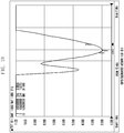
- FIG. 1A is a view illustrating an antenna provided at a lower end of a camera according to the related art
- FIG. 1B is a graph illustrating simulation results of the Voltage Standing Wave Ratio (VSWR) characteristics of the antenna illustrated in FIG. 1A .
- VSWR Voltage Standing Wave Ratio
- FIG. 1A illustrates the shape of an antenna as seen from a lower end of a camera.
- the reference numeral 11 denotes a body of a camera
- 12 denotes a lens of a camera
- 13 denotes an antenna positioned at a lower end of the body of the camera.
- the efficiency of the internal layout of the camera is deteriorated, and this results in the miniaturization and slimming of the camera to be disturbed.
- Document EP 1359 675 discloses a mobile radio terminal with an integrated antenna assembly.
- Document US 2006/093340 discloses a camera comprising an antenna formed in a moveable portion.
- Embodiments of the present invention provide a camera with an antenna that enables easy adjustment of a resonance frequency of the antenna accommodated in the camera.
- Embodiments of the present invention also provide a camera with an antenna that increases a radiation gain through an efficient arrangement of the antenna in the camera to prevent performance deterioration due to limitations caused by the surroundings of the camera or the influence of a hand effect.
- Embodiments of the present invention also provide a camera with an antenna that prevents a deterioration of the radiation gain efficiency of the antenna due to the interference with a body or a lens of the camera that is made of metal.
- Embodiments of the present invention also provide a miniaturized, simple, and slim camera.
- an antenna for a camera comprising a camera having a communication module provided therein, a first radiator provided in a predetermined position of a lens barrel of the camera and having a length and a width for receiving a signal from a first wireless communication system, a power feeding line configured to feed a power from the communication module of the camera to the first radiator, and a ground line configured to ground the first radiator.
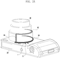
- FIG. 2 is a view illustrating the structure of a camera including an antenna according to an embodiment of the present invention.
- a camera including an antenna may include an injection-molded grip portion 22, a body portion 23, and a lens portion 40.
- the injection-molded grip portion 22 may surround one side surface of the camera and may be fastened to the body portion 23.
- the injection-molded grip portion 22 corresponds to a portion of the camera that is gripped by a user.
- the injection-molded grip portion 22 may be formed by, for example, injection molding.
- the body portion 23 is a cover of the camera that surrounds the entire surface of the camera other than one side surface and a rear surface of the camera, and may be made of a metal material.
- the body portion 23 corresponds to a portion that includes a shutter button, a flash module, a speaker module, an Auto Focus (AF) module, a tripod module, a battery, an SD memory card, a SIM card, and a plug into which an external jack is inserted.
- AF Auto Focus
- a main board may also be provided in the body portion 23.
- the body portion 23 may be formed by injection molding, or may be formed by metal that surrounds the entire outer surface of the injection-molded body portion according to recent design trends.
- the lens portion 40 transmits an image of an object, and includes a lens barrel including at least one lens (hereinafter, the lens portion 40 may be expressed as the lens barrel).
- a typical lens portion 40 includes one or more lenses and has an object focusing function and/or optical zoom function.
- the lens barrel 40 is accommodated in a lens insertion portion formed on a part of the body portion 23.
- the lens barrel 40 may be fixed to the lens insertion portion or may be detachably inserted into the lens insertion portion.
- the lens barrel 40 is configured to accommodate a radiator 42 that is used as an antenna.
- a radiator 42 that is used as an antenna.
- one or two or more radiators may be provided.
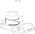
- FIGS. 3A to 3D are views illustrating the structure of an antenna for a camera according to an embodiment of the present invention.
- the antenna may include a first radiator 34 disposed along the circumference of the lens insertion portion and a second radiator 42 disposed in the lens barrel 40.
- the first radiator 34 and the second radiator 42 are antennas for a camera, according to an embodiment of the present invention, to receive radio waves.
- the antenna recognizes the radio wave and resonates to receive the radio wave.
- Data included in the received radio wave is transmitted to a main board (not illustrated) inside the camera.
- the first radiator 34 is accommodated in a part or the entirety of the circumference of the lens insertion portion, or a plurality of radiators may be disposed in the circumference of the lens insertion portion to be spaced apart at a predetermined distance from each other.
- the lens insertion portion may be a region that is trenched with a predetermined depth and a size in which a part of the body portion 23 of the camera is inserted into the lens barrel 40.
- the first radiator 34 may be provided on the body portion 23 of the camera that is adjacent to the lens insertion portion, or may be provided inside the lens insertion portion.
- the first radiator 34 is a radiator having high frequency band characteristics, and has a width that is wider than the width of the second radiator 42 and a length that is shorter than the length of the second radiator 42 to implement a wide band.
- the first radiator 34 is connected to a power feeding portion F that supplies an electric signal and a ground portion G that grounds the first radiator 34.
- the power feeding portion F is connected to the main board inside the camera, and feeds a power to the first radiator 34.
- the ground portion G is connected to the metal that surrounds the body portion 23 of the camera, and grounds the first radiator 34. In particular, since the antenna is grounded using the metal that surrounds the camera body, the broadband characteristics can be implemented.
- the second radiator 42 may be disposed in a part or the entirety of the circumference of the lens barrel 40, or a plurality of radiators may be spaced apart at a predetermined distance from each other.
- the predetermined distance may be defined as a distance in which the plurality of radiators are not influenced by the radio waves and the radiation gain of the antenna is maintained.
- the second radiator 42 may be provided at each stage of the lens barrel 40.
- the second radiator 42 may be implemented as a plurality of radiators mounted at the respective stages of the lens barrel 40 successively come in contact with each other.
- FIG. 3A illustrates an example of the structure in which the first radiator 34 and the second radiator 42 are electrically connected by a connector 44.
- FIG. 3A illustrates an embodiment in which the second radiator 42 is provided on a part of the cross section of the lens barrel 40 that is most adjacent to the body portion 23 of the camera.
- the structure and the shape of the second radiator 42 that is accommodated in the lens barrel 40 is not limited to the structures described above, and it will be understood that any shape of the second radiator 42 may be used as long as it can receive the frequency that is required by the camera.
- the second radiator 42 When the second radiator 42 is connected to the first radiator 34, the power is fed from the power feeding portion F that is connected to the first radiator 34, and the second radiator 42 is grounded by the ground portion G. That is, the second radiator 42 is connected to the first radiator 34 to implement one antenna.
- the second radiator 42 may be disposed in the lens barrel 40 that is drawn out in multi-stage from the lens insertion portion by the zoom-in function in the direction in which the lens barrel 40 is drawn out.
- the second radiator may be disposed in the lens barrel 40 may be drawn out in multi-stage from the lens insertion portion to the outside direction, and when the lens barrel 40 is drawn out in multi-stage, the radiators mounted at the respective stages of the lens barrel 40 successively come in contact with each other.
- the resonance frequency of the second radiator 42 is determined by the length of the entirety of the connected radiators.
- the second radiator 42 includes the connector 44 at one end thereof to be selectively connected to the first radiator 34.
- the connector 44 may have a structure in which the first radiator 34 and the second radiator 42 are in and out of contact with each other as the lens barrel 40 is rotated in a predetermined direction.
- the connector 44 included in the second radiator 42 may be a conductive line for connection between the second radiator 42 and the first radiator 34, or a portion simply to be connected to the first radiator 34. If the connector 44 is a portion simply to be connected to the first radiator 34, the conductive line for connection between the first radiator 34 and the second radiator 42 as illustrated in FIG. 3A may be an extended portion of the second radiator 42.
- the lens barrel 40 having a zoom-out function is in a default state, that is, in a state where the lens barrel 40 is inserted, and in an initial state where the first radiator 34 is not connected to the second radiator 42, only the first radiator 34 operates as the antenna implementing a first resonance frequency, and in a state where the lens barrel 40 projects and the first radiator 34 and the second radiator 42 are connected to each other, the radiators operate as the antenna implementing a second resonance frequency.
- the lens barrel 40 if the lens barrel 40 is in the default state in which the first radiator 34 is spaced apart for a predetermined distance from the second radiator 42, the first radiator 34 and the second radiator 42 may operate as different high-frequency band antennas. If the lens barrel 40 is in the projecting state in which the first radiator 34 comes in contact with the second radiator 42, the two radiators are connected to each other to operate as a low-frequency band radiator.
- the first radiator 34 which is spaced apart from the second radiator 42 by the predetermined distance, may operate as a coupling antenna by the coupling that occurs between the first radiator 34 and the second radiator 42.
- the first radiator 34 may operate as a Wi-Fi antenna, and in the projected state, the first radiator 34 and the second radiator 42 may operate as a GPS antenna.
- FIG. 3B illustrates an example in which the first radiator 34 and the second radiator 42 are in a non-contact state, in which the lens barrel 40 is rotated from its orientation in FIG. 3A in a predetermined direction to move the connector 44, and the second radiator 42 is spaced apart from the first radiator 34.
- the first radiator 34 and the second radiator 42 may implement different resonance frequencies according to the contact or non-contact state between the first radiator 34 and the second radiator 42. Further, the first radiator 34 may be implemented as a single antenna or a coupling antenna depending on the gap distance between the first radiator 34 and the second radiator 42.
- the first radiator 34 is spaced apart from the second radiator 42 by a predetermined distance, it is not affected by the radio wave or metal interference of the second radiator 42, but may be implemented as a single antenna.
- the first radiator 34 may be implemented as a single antenna, and for example, through implementation of the resonance frequency characteristics of 2.4 GHz and 5 GHz, it may be implemented as a Wi-Fi antenna.
- the gap distance between the first radiator 34 and the second radiator 42 may be adjusted by moving the second radiator 42 towards/away from the first radiator 34 through rotation of the lens barrel 40.
- the first radiator 34 comes in contact with the second radiator 42 by the connector 44 of the second radiator 42 and is electrically connected to the second radiator 42 to implement the second resonance frequency. That is, the first radiator 34 may be implemented as a single antenna or a coupling antenna in a state in which the first radiator 34 is spaced apart from the second radiator 42. If the first radiator 34 comes in contact with the second radiator 42 by the rotation of the lens barrel 40, a composite radiator having a length that is obtained by adding the length of the first radiator 34 to the length of the second radiator 42 may be provided. Since the length of the second radiator 42 is added to the length of the first radiator 34, a relatively low frequency band can be implemented.
- the radiator may be implemented as at least one of a Bluetooth (BT) antenna, a Global Positioning System (GPS) antenna, a Global System for Mobile communication (GSM) antenna, a Code Division Multiple Access (CDMA) antenna, and a Wideband CDMA (WCDMA) antenna, and a diversity antenna.
- BT Bluetooth
- GPS Global Positioning System
- GSM Global System for Mobile communication
- CDMA Code Division Multiple Access
- WCDMA Wideband CDMA
- FIG. 4 is a graph illustrating simulation results of the VSWR characteristics of a first radiator according to an embodiment of the present invention.
- FIG. 5 is a graph illustrating simulation results of the VSWR characteristics of a first radiator and a second radiator according to an embodiment of the present invention.
- the resonance frequency of the first radiator 34 illustrated in FIG. 3B indicates the radiation pattern of a Wi-Fi band (2.4 GHz and 5 GHz) that is the high frequency band among the frequency bands of the antenna for a camera.
- a Wi-Fi band 2.4 GHz and 5 GHz
- the resonance frequency of the first radiator 34 and the second radiator 42 illustrated in FIG. 3A indicates the radiation pattern of a GPS band (1.5 GHz) that is a relatively low frequency band among the frequency bands of the antenna for a camera.
- the resonance frequency of the antenna can be easily adjusted using the first radiator 34 that operates as the first antenna and the second antenna that operates as one antenna when the first radiator 34 and the second radiator 42 are selectively connected to each other.
- the first radiator 34 is spaced apart from the second radiator 42 by a predetermined distance, it functions as an antenna having the high-frequency band characteristics, whereas if the first radiator 34 is directly connected to the second radiator 42, it functions as an antenna having the low-frequency band characteristics.
- the resonance frequency can be adjusted.
- FIGS. 3C and 3D are views schematically illustrating the structure of a coupling antenna according to an embodiment of the present invention.
- the first radiator 34 and the second radiator 42 may be coupling antennas implemented by a coupling that is induced in a state in which the first radiator 34 and the second radiator 42 are in a non-contact state and are spaced apart from each other by a predetermined adjacent distance.
- the coupling may be defined as a phenomenon in which, as ends of a high frequency band and a low frequency band approach each other, bandwidth extension of the high and low frequency bands and the movement characteristic of the high frequency to a center frequency occur, and movement to a desired band becomes possible through appropriate tuning.
- the first radiator 34 and the second radiator 42 may have an induced coupling value that is adjusted depending on the gap distance.
- the distance between the first radiator 34 and the second radiator 42 may be adjusted in accordance with the degree of extension of the lens barrel 40 through the zoom-in function.
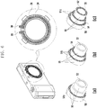
- FIG. 6 is a view illustrating various structures of a second radiator of an antenna for a camera according to an embodiment of the present invention.
- the second radiator of the antenna may include different lengths in accordance with a plurality of lens barrels.
- the lens barrel 55 may be configured in an extendable form as illustrated in FIG. 6 and may include an object lens 52. Further, the barrel 55 may include a plurality of lenses (not illustrated in the drawing). A barrel portion having the widest radius of the barrel 55 may include a radiator that operates as a Wi-Fi antenna. This is illustrated in (a) of FIG. 6 . If the barrel 55 is configured in three stages, the barrel portion having the secondly wide radius may include a radiator that operates as an RFID antenna 54. This is illustrated in (b) of FIG. 6 . If the barrel 55 is configured in three stages, a barrel portion having the smallest radius to operate as a telephoto lens may include a radiator that operates as an NFC antenna. This is illustrated in (c) of FIG. 6 .
- the respective antennas as described above are merely exemplary, and various types of antennas may be configured to receive different frequencies. That is, second radiators for different antennas may be achieved with different lengths for a plurality of lenses that are detachably attached to the camera.
- the second radiator as described above may be connected to the first radiator 34 to implement an integrated antenna and the second radiator, instead of the first radiator 34, may be embodied as one antenna.
- the first radiator may include a body portion 23 of the camera.
- the first radiator of the lens portion for example, the radiator 53 exemplified in (a) of FIG. 6 , may be the first radiator, which however would not be in line with the present claims.
- the radiator may be positioned in parallel to the object lens 52, the radiator may be positioned on the circumference where the barrel is extended.
- the first radiator 34 is positioned on the body portion 23 of the camera.
- the second radiator may include contact portions 51a that are provided between the respective stages of the lens barrel 40 to selectively connect the plurality of radiators, which are disposed at the respective stages of the lens barrel 40, and the adjacent radiators.
- the contact portions 51a of the second radiator is configured to connect the plurality of radiators disposed at the respective stages of the lens barrel 40 while the lens barrel 40 is rotated to be extended.
- the contact portions 51 may be provided as radiators having the same material as the material of the plurality of radiators.
- the respective contact portions 51a, 51b, and 51c may be mounted on surfaces of parts of the respective stages of the lens barrel 40.
- the contact portions 51 mounted on the different stages may come in contact with each other, thereby becoming electrically connected to each other, as the plurality of stages project outwardly.
- the contact portions 51 as described above may selectively connect the plurality of radiators disposed at the respective stages of the lens barrel 40 to adjust the second resonance frequency as the lens barrel 40 is rotated in the predetermined direction.
- the contact portions 51 mounted on the respective stages may be selectively connected to each other depending on the direction in which the lens barrel 40 is rotated according to a user input. That is, a user may cause the contact portions 51 mounted on the neighboring stages come in contact with each other or be spaced apart from each other through adjustment of the rotation of the lens barrel 40.
- the antennas are implemented on the lens barrel 40 and/or the lens insertion portion, a separate area for installing the antennas in the camera is not required, and thus, the inner space efficiency of the camera is improved.
- the first radiator 34 and the second radiator 42 may be provided as at least one conductive metal pattern in a metal sheet, a tin lamination pattern, a FPCB pattern, and a film pattern.
- electromagnetic wave shielding films on which copper and nickel are plated, may be further provided on the body portion 23, between the lens barrel 40, and/or on the lower portion of the lens insertion portion.
- the reference numerals 36 and 38 denote configuration to be connected to a portion for feeding the power to the antenna
- 39 denotes a shield for preventing foreign substances from flowing into the body of the camera.
- the first radiator 34 which is composed of a conductor that forms the first antenna, is exemplified.
- FIG. 7 is a view illustrating the structure of an antenna for a camera according to an example.
- FIG. 8 is a view illustrating the structure in which an antenna for a camera according to an example is implemented on a camera filter.
- the antenna may include one or more radiators 62 and 72 provided at distal end 80 of the lens barrel 40 (i.e., at a farthest projected region).
- the respective radiators 62 and 72 may receive power from the main board (not shown) of the camera through connection wires (not shown) connected to the inside of the lens barrel, and may be connected to a metal body portion 23 of the camera to be grounded. Further, a coupling antenna, which is provided through coupling induced between the radiators 62 and 72, may be implemented. Further, the reference numerals 62 and 64 denote a power feeding line and a ground line of the respective antennas as described above.
- the antenna may include a third radiator provided along the circumference of a lens filter frame 90 of the camera.
- the third radiator may be provided so that two or more radiators 92 and 95 are spaced apart from each other by a predetermined distance, receive power from the main board of the camera through the wires (not shown) connected to the inside of the lens barrel, and may be connected to the metal body portion 23 of the camera to be grounded.
- the third radiator may be implemented as a coupling antenna through coupling, induced between the plurality of radiators 92 and 95.
- the thickness and the length of the third radiator may be determined based on the resonance frequency of the antenna.
- the third radiator may be provided as a plurality of radiators that are spaced apart from each other by a predetermined distance on the lens filter frame 90 of the camera.
- the reference numerals 93, 94, 96, and 97 denote power feeding lines and ground lines of the respective antennas.
- the predetermined distance between the plurality of third radiators may be defined as a distance in which the radiation gain of the antenna can be achieved without causing radio wave influence between the plurality of radiators.
- the third radiator may be connected to the power feeding portion F supplying the electric signal and the ground portion G grounding the first radiator.
- the power feeding portion F may be connected to the main board inside the camera to feed the power to the third radiator.
- the ground portion G may be connected to the metal that surrounds the body portion 23 of the camera to ground the third radiator.
- the antennas are grounded using the metal surrounding the camera body, and thus the broadband characteristic is achieved.
- FIG. 9 is a view illustrating the structure of an antenna for a camera according to another example.
- FIG. 9 illustrates an antenna for a camera that projects from one surface of the camera body 23, which is surrounded by the metal, and is provided on the camera that includes the lens barrel having an injection-molded outer surface that is surrounded by metal.
- the antenna for a camera illustrated in FIG. 9 includes slit radiators 100 and 105 that are disposed along at least a part of the circumference of the injection-molded outer surface of the lens barrel 40 and is spaced apart from the metal of the camera body 23 by a predetermined distance.
- the slit radiators 100 and 105 is barely affected by the radio waves because of the metal, and may be spaced apart from the metal by a predetermined distance large enough to achieve the radiation gain of the antenna. For example, by removing a part of the metal that surrounds the lens barrel 40 to mount the antenna, a radiation gain extension region of the antenna can be achieved.
- the slit radiators 100 and 105 may be disposed in the radiation gain extension region.
- the slit radiators 100 and 105 may be connected to the main board of the camera by the power feeding portion 120 that feeds power to the slit radiator 100. Further, the slit radiator 100 may be connected to the ground portion 140 that grounds the slit radiator 100 through the body portion 23 of the camera.
- One or more slit radiators 100 and 105 may be disposed along at least a part of the circumference of a part of the injection-molded outer surface of the lens barrel 40 on the basis of the form exemplified in FIG. 10 , and may be spaced apart from each other by a predetermined distance if a plurality of slit radiators are provided as an example that is different from the form illustrated in FIG. 10 .
- the slit radiators 100 may be implemented with different lengths and widths, and thus may be implemented as antennas having different resonance frequencies.
- FIG. 10 is a graph illustrating simulation results of the VSWR characteristics of a slit radiator according to an example.
- the slit radiator 100 and 105 illustrated in FIG. 9 has a radiation pattern having the resonance frequency band of 1.5 GHz.
- the resonance frequency of the slit radiators 100 and 105 are the radiation pattern of the GPS band
- the resonance frequency can be adjusted through the adjustment of the implemented length or width and the inductive coupling with an adjacent radiator.
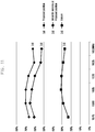
- FIG. 11 is a graph illustrating the antenna radiation gain efficiencies of an antenna radiator according to an example versus an antenna radiator in the related art.
- the radiators (a) and the slit radiator (b), provided along the extension direction of the lens insertion portion, and the lens barrel according to an example have a radiation gain efficiency that is quite higher than the radiation gain efficiency of the antennas (c) mounted on the bottom surface of the camera as in the related art.
- the antenna according to an example can prevent the deterioration of the radiation gain efficiency caused by interference with other metal portions, and is implemented at a position where the antenna radio wave radiation is optimal to improve the radiation gain efficiency.
- FIG. 12 is a view illustrating the fastening structure of an antenna for a camera, according to an example.
- the power feeding portion F and the ground portion G of the antenna may be formed on the camera using at least one of a spring 130, a C clip 140, and a soldering(not illustrated in the drawing).
- FIG. 13 is a view explaining a connection between a power feeding portion F and a ground portion G of an antenna for a camera and a circuit according to an example.
- FIG. 13 is a view explaining the connection between the power feeding portion F and the ground portion G and the circuit board after the power feeding portion F and the ground portion G, which are provided at one end of the radiator of the antenna through the configuration of FIG. 12 , are connected to each other.
- a projection type power feeding portion 162 is provided on the circuit board 160 for power feeding to the antenna, and a cable 170 that is connected to one end of the antenna may be configured in the form of a socket 180 into which the projection type power feeding portion 162 can be inserted.
- the cable 170 having the socket 180 may be fastened to the circuit board 160, and as exemplified in (b) of FIG. 13 , the cable 170 having the socket 180 may be separated from the circuit board 160.
- the projection type power feeding portion 162 may also have a ground line.
- the ground line may be a portion having a cylindrical pole shape 163 that surrounds the projection type outline.
- two different conductive lines are provided inside the cable 170.
- One conductive line may be a conductive line for power feeding, and the other conductive line may be a conductive line for grounding.
- the respective conductive lines included in the cable 170 may be surrounded by an insulator. Further, two conductive lines surrounded by the insulator may be included in one cable 170.
- the radiators having different structures are provided for the plurality of lens barrels that are detachably attached to the camera, and thus the antennas having different frequency bands can be selectively utilized by the camera.
- the resonance frequency of the antenna can be easily changed.
- the broadband characteristics of the antenna can be implemented.
- the antennas in the form of a slit that is spaced apart from the metal body by a predetermined distance, the deterioration of the radiation gain efficiency of the antenna caused by the interference with other metal parts can be prevented.
Description
- The present disclosure generally relates a camera with an antenna, and more particularly, with an antenna that is accommodated in a lens barrel, which is detachably attached to the camera to zoom out, to adjust resonance frequencies.
- In general, a digital camera is a device that converts light reflected from an object into an electrical signal, stores the converted electric signal as image data, and processes or reproduces the stored image data.
- Since the digital camera does not use a film, development, photo printing, and/or enlargement processes are not required, and both a still image and a moving image can be captured and stored.
- Further, the ways in which the digital camera may be utilized have gradually increased. For example, captured image data may be stored in a storage device of a computer, such as a computer memory, a CD-ROM, or a USB memory, or may be transmitted to a desired person through an e-mail.
- That is, since the digital camera can easily edit and process the captured image data using digital media, it has quickly replaced the need for a film camera.
- Because aesthetic factors of the digital camera have recently influenced product sales greatly, the design of the product has been recognized as an important factor in addition to the performance of the product.
- Further, although a number of components of the digital camera have increased with the gradual convergence of many functions to the digital camera, users usually prefer a simple design.
- Digital cameras, on which various functions are mounted in compliance with various desires of consumers, have recently been developed, and among them, is a digital camera having a built-in antenna module.
- A built in antenna module enables the camera to directly perform multimedia data communication.
- For example, data of an image or a moving image captured through the camera can be transmitted to another electronic device through a Wi-Fi antenna, or position information can be provided using satellite information that is received from a satellite through a GPS module.
- The shape of such a built-in antenna has been changed in accordance with the trend of a miniaturized and slim communication terminal.
- That is, as the type of antenna varies, a region where other components are arranged is further required, and as the size of the camera becomes smaller, it is necessary to further reduce the size or thickness of the antenna and to arrange the antenna on a main board of the camera.
- However, since the length of the antenna is typically proportional to the frequency wavelength, reduction of the size of an antenna for receiving a high frequency band, for example, a GPS antenna, is restricted to a specific length.
- Further, in the case of dispersing and arranging a plurality of antennas on several regions in the camera, it is required that a main Printed Circuit Board (PCB), an electronic object such as a battery, and metal components are arranged to be spaced apart from each other.
- According to the characteristics of the antenna, an upper end portion of the camera is optimal for improving the performance of the antenna. However, it is difficult to ensure a space due to the influence of a power, a shutter, and a zoom. The left or right side of the camera may affect the performance due to a hand effect, and the lower end portion of the camera may be affected by use of a tripod or a battery.
-
FIG. 1A is a view illustrating an antenna provided at a lower end of a camera according to the related art, andFIG. 1B is a graph illustrating simulation results of the Voltage Standing Wave Ratio (VSWR) characteristics of the antenna illustrated inFIG. 1A . - Referring to
FIGS. 1A and1B , if the antenna is arranged at the lower end of the camera, as can be seen from the graph ofFIG. 1B , the frequency bandwidth becomes narrow, and radiation gain efficiency is not high.FIG. 1A illustrates the shape of an antenna as seen from a lower end of a camera. Thereference numeral 11 denotes a body of a camera, 12 denotes a lens of a camera, and 13 denotes an antenna positioned at a lower end of the body of the camera. - Further, due to the dispersed arrangement of the plurality of antennas, the efficiency of the internal layout of the camera is deteriorated, and this results in the miniaturization and slimming of the camera to be disturbed.
- Accordingly, there is a need for development of a camera that maximizes the performance of the antenna and improves the simplicity and aesthetic design of the external appearance of the camera even in a state in which antennas of various frequency bands are mounted on the camera.
DocumentEP 1359 675 discloses a mobile radio terminal with an integrated antenna assembly.
DocumentUS 2006/093340 discloses a camera comprising an antenna formed in a moveable portion. - There is provided a camera with an antenna accommodated within a rotatable lens barrel of the camera wherein the lens barrel is rotatable into an extended position from the camera, as set out in
claim 1. - The present disclosure has been made to address at least the above problems and disadvantages, and to provide at least the advantages described below. Embodiments of the present invention provide a camera with an antenna that enables easy adjustment of a resonance frequency of the antenna accommodated in the camera.
- Embodiments of the present invention also provide a camera with an antenna that increases a radiation gain through an efficient arrangement of the antenna in the camera to prevent performance deterioration due to limitations caused by the surroundings of the camera or the influence of a hand effect.
- Embodiments of the present invention also provide a camera with an antenna that prevents a deterioration of the radiation gain efficiency of the antenna due to the interference with a body or a lens of the camera that is made of metal.
- Embodiments of the present invention also provide a miniaturized, simple, and slim camera.
- In accordance with an aspect of the present invention, an antenna for a camera, comprising a camera having a communication module provided therein, a first radiator provided in a predetermined position of a lens barrel of the camera and having a length and a width for receiving a signal from a first wireless communication system, a power feeding line configured to feed a power from the communication module of the camera to the first radiator, and a ground line configured to ground the first radiator.
- The above and other aspects, features, and advantages of the present invention will be more apparent from the following detailed description taken in conjunction with the accompanying drawings, in which;
-
FIG. 1A is a view illustrating an antenna provided at a lower end of a camera according to the related art; -
FIG. 1B is a graph illustrating simulation results of the VSWR characteristics of the antenna illustrated inFIG. 1A according to the related art; -
FIG. 2 is a view illustrating the structure of a camera including an antenna according to an embodiment of the present invention; -
FIGS. 3A to 3D are views schematically illustrating the structure of an antenna for a camera according to an embodiment of the present invention; -
FIG. 4 is a graph illustrating simulation results of the VSWR characteristics of a first radiator according to an embodiment of the present invention; -
FIG. 5 is a graph illustrating simulation results of the VSWR characteristics of a first radiator and a second radiator according to an embodiment of the present invention; -
FIG. 6 is a view illustrating various structures of a second radiator of an antenna for a camera according to an embodiment of the present invention; -
FIG. 7 is a view illustrating the structure of an antenna for a camera according to an example; -
FIG. 8 is a view illustrating the structure in which an antenna for a camera according to an example is implemented on a filter; -
FIG. 9 is a view illustrating the structure of an antenna for a camera according to another example; -
FIG. 10 is a graph illustrating simulation results of the VSWR characteristics of a slit radiator according to an example; -
FIG. 11 is a graph illustrating the antenna radiation gain efficiencies of an antenna radiator according to an example versus an antenna radiator according to the related art; and -
FIG. 12 is a view illustrating the fastening structure of an antenna for a camera according to an example; -
FIG. 13 is a view explaining a connection between a power feeding portion and a ground portion of an antenna for a camera and a circuit according to an example. - Hereinafter, embodiments of the present invention and examples not forming part but being useful for understanding the invention will be described in detail with reference to the accompanying drawings to the extent that those of ordinary skill in the art to which the present disclosure pertains can easily understand the description.
- In the following description of the present invention, a detailed description of the technical contents that are well known in the technical field, to which the present disclosure pertains, and are not directly related to the present invention will be omitted. By omitting such an unnecessary description, the subject matter of the present invention will become quite clear.
- For the same reason, in the drawings, some constituent elements are exaggerated, omitted, or schematically illustrated. Further, the sizes of the respective constituent elements may not entirely reflect the actual sizes. In the entire description of the present invention, the same drawing reference numerals are used to refer to the same constituent elements across various figures.
-
FIG. 2 is a view illustrating the structure of a camera including an antenna according to an embodiment of the present invention. - Referring to
FIG. 2 , a camera including an antenna according to an embodiment of the present invention may include an injection-moldedgrip portion 22, abody portion 23, and alens portion 40. The injection-moldedgrip portion 22 may surround one side surface of the camera and may be fastened to thebody portion 23. The injection-moldedgrip portion 22 corresponds to a portion of the camera that is gripped by a user. The injection-moldedgrip portion 22 may be formed by, for example, injection molding. - The
body portion 23 is a cover of the camera that surrounds the entire surface of the camera other than one side surface and a rear surface of the camera, and may be made of a metal material. Thebody portion 23 corresponds to a portion that includes a shutter button, a flash module, a speaker module, an Auto Focus (AF) module, a tripod module, a battery, an SD memory card, a SIM card, and a plug into which an external jack is inserted. In addition, a main board may also be provided in thebody portion 23. - The
body portion 23 may be formed by injection molding, or may be formed by metal that surrounds the entire outer surface of the injection-molded body portion according to recent design trends. - The
lens portion 40 transmits an image of an object, and includes a lens barrel including at least one lens (hereinafter, thelens portion 40 may be expressed as the lens barrel). Atypical lens portion 40 includes one or more lenses and has an object focusing function and/or optical zoom function. - The
lens barrel 40 is accommodated in a lens insertion portion formed on a part of thebody portion 23. For example, thelens barrel 40 may be fixed to the lens insertion portion or may be detachably inserted into the lens insertion portion. - In particular, the
lens barrel 40 is configured to accommodate aradiator 42 that is used as an antenna. In this case, one or two or more radiators may be provided. - Hereinafter, a
radiator 34, and theradiator 42 provided on thelens barrel 40 will be described in detail with reference to the drawings.FIGS. 3A to 3D are views illustrating the structure of an antenna for a camera according to an embodiment of the present invention. - Referring to
FIG. 3A , the antenna may include afirst radiator 34 disposed along the circumference of the lens insertion portion and asecond radiator 42 disposed in thelens barrel 40. - The
first radiator 34 and thesecond radiator 42 are antennas for a camera, according to an embodiment of the present invention, to receive radio waves. - If a radio wave that has the same resonance frequency band as the resonance frequency band of the antenna is emitted from a base station, the antenna recognizes the radio wave and resonates to receive the radio wave. Data included in the received radio wave is transmitted to a main board (not illustrated) inside the camera.
- Specifically, the
first radiator 34 is accommodated in a part or the entirety of the circumference of the lens insertion portion, or a plurality of radiators may be disposed in the circumference of the lens insertion portion to be spaced apart at a predetermined distance from each other. The lens insertion portion may be a region that is trenched with a predetermined depth and a size in which a part of thebody portion 23 of the camera is inserted into thelens barrel 40. - The
first radiator 34 may be provided on thebody portion 23 of the camera that is adjacent to the lens insertion portion, or may be provided inside the lens insertion portion. - The
first radiator 34 is a radiator having high frequency band characteristics, and has a width that is wider than the width of thesecond radiator 42 and a length that is shorter than the length of thesecond radiator 42 to implement a wide band. - The
first radiator 34 is connected to a power feeding portion F that supplies an electric signal and a ground portion G that grounds thefirst radiator 34. - The power feeding portion F is connected to the main board inside the camera, and feeds a power to the
first radiator 34. The ground portion G is connected to the metal that surrounds thebody portion 23 of the camera, and grounds thefirst radiator 34. In particular, since the antenna is grounded using the metal that surrounds the camera body, the broadband characteristics can be implemented. - The
second radiator 42 may be disposed in a part or the entirety of the circumference of thelens barrel 40, or a plurality of radiators may be spaced apart at a predetermined distance from each other. The predetermined distance may be defined as a distance in which the plurality of radiators are not influenced by the radio waves and the radiation gain of the antenna is maintained. - In the case in which the
lens barrel 40, which projects from thebody portion 23 of the camera as illustrated inFIG. 3A , has a multi-stage structure in which the cross-sectional area thereof is gradually narrowed, thesecond radiator 42 may be provided at each stage of thelens barrel 40. - When the
lens barrel 40 is drawn out in multi-stage, thesecond radiator 42 may be implemented as a plurality of radiators mounted at the respective stages of thelens barrel 40 successively come in contact with each other. -
FIG. 3A illustrates an example of the structure in which thefirst radiator 34 and thesecond radiator 42 are electrically connected by aconnector 44. -
FIG. 3A illustrates an embodiment in which thesecond radiator 42 is provided on a part of the cross section of thelens barrel 40 that is most adjacent to thebody portion 23 of the camera. However, the structure and the shape of thesecond radiator 42 that is accommodated in thelens barrel 40 is not limited to the structures described above, and it will be understood that any shape of thesecond radiator 42 may be used as long as it can receive the frequency that is required by the camera. - When the
second radiator 42 is connected to thefirst radiator 34, the power is fed from the power feeding portion F that is connected to thefirst radiator 34, and thesecond radiator 42 is grounded by the ground portion G. That is, thesecond radiator 42 is connected to thefirst radiator 34 to implement one antenna. - The
second radiator 42 may be disposed in thelens barrel 40 that is drawn out in multi-stage from the lens insertion portion by the zoom-in function in the direction in which thelens barrel 40 is drawn out. - That is, the second radiator may be disposed in the
lens barrel 40 may be drawn out in multi-stage from the lens insertion portion to the outside direction, and when thelens barrel 40 is drawn out in multi-stage, the radiators mounted at the respective stages of thelens barrel 40 successively come in contact with each other. - Further, as the radiators provided at the respective stages are connected to each other when the
lens barrel 40 is drawn out, the resonance frequency of thesecond radiator 42 is determined by the length of the entirety of the connected radiators. - The
second radiator 42 includes theconnector 44 at one end thereof to be selectively connected to thefirst radiator 34. Theconnector 44 may have a structure in which thefirst radiator 34 and thesecond radiator 42 are in and out of contact with each other as thelens barrel 40 is rotated in a predetermined direction. Further, as illustrated inFIG. 3A , theconnector 44 included in thesecond radiator 42 may be a conductive line for connection between thesecond radiator 42 and thefirst radiator 34, or a portion simply to be connected to thefirst radiator 34. If theconnector 44 is a portion simply to be connected to thefirst radiator 34, the conductive line for connection between thefirst radiator 34 and thesecond radiator 42 as illustrated inFIG. 3A may be an extended portion of thesecond radiator 42. - According to such a configuration, the
lens barrel 40 having a zoom-out function is in a default state, that is, in a state where thelens barrel 40 is inserted, and in an initial state where thefirst radiator 34 is not connected to thesecond radiator 42, only thefirst radiator 34 operates as the antenna implementing a first resonance frequency, and in a state where thelens barrel 40 projects and thefirst radiator 34 and thesecond radiator 42 are connected to each other, the radiators operate as the antenna implementing a second resonance frequency. - In other words, if the
lens barrel 40 is in the default state in which thefirst radiator 34 is spaced apart for a predetermined distance from thesecond radiator 42, thefirst radiator 34 and thesecond radiator 42 may operate as different high-frequency band antennas. If thelens barrel 40 is in the projecting state in which thefirst radiator 34 comes in contact with thesecond radiator 42, the two radiators are connected to each other to operate as a low-frequency band radiator. - Further, when the
lens barrel 40 is in the projected state, thefirst radiator 34, which is spaced apart from thesecond radiator 42 by the predetermined distance, may operate as a coupling antenna by the coupling that occurs between thefirst radiator 34 and thesecond radiator 42. - Accordingly, in the default state, the
first radiator 34 may operate as a Wi-Fi antenna, and in the projected state, thefirst radiator 34 and thesecond radiator 42 may operate as a GPS antenna. -
FIG. 3B illustrates an example in which thefirst radiator 34 and thesecond radiator 42 are in a non-contact state, in which thelens barrel 40 is rotated from its orientation inFIG. 3A in a predetermined direction to move theconnector 44, and thesecond radiator 42 is spaced apart from thefirst radiator 34. - Referring to
FIGS. 3A and3B , thefirst radiator 34 and thesecond radiator 42 may implement different resonance frequencies according to the contact or non-contact state between thefirst radiator 34 and thesecond radiator 42. Further, thefirst radiator 34 may be implemented as a single antenna or a coupling antenna depending on the gap distance between thefirst radiator 34 and thesecond radiator 42. - That is, if the
first radiator 34 is spaced apart from thesecond radiator 42 by a predetermined distance, it is not affected by the radio wave or metal interference of thesecond radiator 42, but may be implemented as a single antenna. Thefirst radiator 34 may be implemented as a single antenna, and for example, through implementation of the resonance frequency characteristics of 2.4 GHz and 5 GHz, it may be implemented as a Wi-Fi antenna. - The gap distance between the
first radiator 34 and thesecond radiator 42 may be adjusted by moving thesecond radiator 42 towards/away from thefirst radiator 34 through rotation of thelens barrel 40. - Hereinafter, an inductive coupling antenna between the
first radiator 34 and thesecond radiator 42 will be described later with reference toFIGS. 3C and3D . - As shown in
FIG. 3A , thefirst radiator 34 comes in contact with thesecond radiator 42 by theconnector 44 of thesecond radiator 42 and is electrically connected to thesecond radiator 42 to implement the second resonance frequency. That is, thefirst radiator 34 may be implemented as a single antenna or a coupling antenna in a state in which thefirst radiator 34 is spaced apart from thesecond radiator 42. If thefirst radiator 34 comes in contact with thesecond radiator 42 by the rotation of thelens barrel 40, a composite radiator having a length that is obtained by adding the length of thefirst radiator 34 to the length of thesecond radiator 42 may be provided. Since the length of thesecond radiator 42 is added to the length of thefirst radiator 34, a relatively low frequency band can be implemented. - For example, the radiator may be implemented as at least one of a Bluetooth (BT) antenna, a Global Positioning System (GPS) antenna, a Global System for Mobile communication (GSM) antenna, a Code Division Multiple Access (CDMA) antenna, and a Wideband CDMA (WCDMA) antenna, and a diversity antenna.
-
FIG. 4 is a graph illustrating simulation results of the VSWR characteristics of a first radiator according to an embodiment of the present invention.FIG. 5 is a graph illustrating simulation results of the VSWR characteristics of a first radiator and a second radiator according to an embodiment of the present invention. - Referring to
FIG. 4 , it is shown that the resonance frequency of thefirst radiator 34 illustrated inFIG. 3B indicates the radiation pattern of a Wi-Fi band (2.4 GHz and 5 GHz) that is the high frequency band among the frequency bands of the antenna for a camera. - Referring to
FIG. 5 , it is shown that the resonance frequency of thefirst radiator 34 and thesecond radiator 42 illustrated inFIG. 3A indicates the radiation pattern of a GPS band (1.5 GHz) that is a relatively low frequency band among the frequency bands of the antenna for a camera. - As shown in the graphs of the simulation results of
FIGS. 4 and5 , it is shown that the resonance frequency of the antenna can be easily adjusted using thefirst radiator 34 that operates as the first antenna and the second antenna that operates as one antenna when thefirst radiator 34 and thesecond radiator 42 are selectively connected to each other. - That is, if the
first radiator 34 is spaced apart from thesecond radiator 42 by a predetermined distance, it functions as an antenna having the high-frequency band characteristics, whereas if thefirst radiator 34 is directly connected to thesecond radiator 42, it functions as an antenna having the low-frequency band characteristics. - Further, by adjusting the length of the
second radiator 42, the resonance frequency can be adjusted. -
FIGS. 3C and3D are views schematically illustrating the structure of a coupling antenna according to an embodiment of the present invention. - Referring to
FIGS. 3C and3D , thefirst radiator 34 and thesecond radiator 42 may be coupling antennas implemented by a coupling that is induced in a state in which thefirst radiator 34 and thesecond radiator 42 are in a non-contact state and are spaced apart from each other by a predetermined adjacent distance. - Here, the coupling may be defined as a phenomenon in which, as ends of a high frequency band and a low frequency band approach each other, bandwidth extension of the high and low frequency bands and the movement characteristic of the high frequency to a center frequency occur, and movement to a desired band becomes possible through appropriate tuning.
- The
first radiator 34 and thesecond radiator 42 may have an induced coupling value that is adjusted depending on the gap distance. The distance between thefirst radiator 34 and thesecond radiator 42 may be adjusted in accordance with the degree of extension of thelens barrel 40 through the zoom-in function. -
FIG. 6 is a view illustrating various structures of a second radiator of an antenna for a camera according to an embodiment of the present invention. - Referring to
FIG. 6 , the second radiator of the antenna may include different lengths in accordance with a plurality of lens barrels. - For example, the
lens barrel 55 may be configured in an extendable form as illustrated inFIG. 6 and may include anobject lens 52. Further, thebarrel 55 may include a plurality of lenses (not illustrated in the drawing). A barrel portion having the widest radius of thebarrel 55 may include a radiator that operates as a Wi-Fi antenna. This is illustrated in (a) ofFIG. 6 . If thebarrel 55 is configured in three stages, the barrel portion having the secondly wide radius may include a radiator that operates as anRFID antenna 54. This is illustrated in (b) ofFIG. 6 . If thebarrel 55 is configured in three stages, a barrel portion having the smallest radius to operate as a telephoto lens may include a radiator that operates as an NFC antenna. This is illustrated in (c) ofFIG. 6 . The respective antennas as described above are merely exemplary, and various types of antennas may be configured to receive different frequencies. That is, second radiators for different antennas may be achieved with different lengths for a plurality of lenses that are detachably attached to the camera. - It will be apparent to those skilled in the art that the second radiator as described above may be connected to the
first radiator 34 to implement an integrated antenna and the second radiator, instead of thefirst radiator 34, may be embodied as one antenna. As described above, the first radiator may include abody portion 23 of the camera. However, the first radiator of the lens portion, for example, theradiator 53 exemplified in (a) ofFIG. 6 , may be the first radiator, which however would not be in line with the present claims. Further, although it is exemplified that the radiator is positioned in parallel to theobject lens 52, the radiator may be positioned on the circumference where the barrel is extended. Hereinafter, for convenience in explanation, it is assumed that thefirst radiator 34 is positioned on thebody portion 23 of the camera. - On the other hand, the second radiator may include
contact portions 51a that are provided between the respective stages of thelens barrel 40 to selectively connect the plurality of radiators, which are disposed at the respective stages of thelens barrel 40, and the adjacent radiators. - The
contact portions 51a of the second radiator is configured to connect the plurality of radiators disposed at the respective stages of thelens barrel 40 while thelens barrel 40 is rotated to be extended. The contact portions 51 may be provided as radiators having the same material as the material of the plurality of radiators. - The
respective contact portions lens barrel 40. The contact portions 51 mounted on the different stages may come in contact with each other, thereby becoming electrically connected to each other, as the plurality of stages project outwardly. - The contact portions 51 as described above may selectively connect the plurality of radiators disposed at the respective stages of the
lens barrel 40 to adjust the second resonance frequency as thelens barrel 40 is rotated in the predetermined direction. - In this case, the contact portions 51 mounted on the respective stages may be selectively connected to each other depending on the direction in which the
lens barrel 40 is rotated according to a user input. That is, a user may cause the contact portions 51 mounted on the neighboring stages come in contact with each other or be spaced apart from each other through adjustment of the rotation of thelens barrel 40. - As described above, since the antennas are implemented on the
lens barrel 40 and/or the lens insertion portion, a separate area for installing the antennas in the camera is not required, and thus, the inner space efficiency of the camera is improved. - The
first radiator 34 and thesecond radiator 42 may be provided as at least one conductive metal pattern in a metal sheet, a tin lamination pattern, a FPCB pattern, and a film pattern. - Although not illustrated, in order to shield electromagnetic waves generated from other electronic components of the camera, electromagnetic wave shielding films, on which copper and nickel are plated, may be further provided on the
body portion 23, between thelens barrel 40, and/or on the lower portion of the lens insertion portion. Further, thereference numerals first radiator 34, which is composed of a conductor that forms the first antenna, is exemplified.FIG. 7 is a view illustrating the structure of an antenna for a camera according to an example.FIG. 8 is a view illustrating the structure in which an antenna for a camera according to an example is implemented on a camera filter. - Referring to
FIG. 7 , the antenna may include one ormore radiators distal end 80 of the lens barrel 40 (i.e., at a farthest projected region). - The
respective radiators metal body portion 23 of the camera to be grounded. Further, a coupling antenna, which is provided through coupling induced between theradiators reference numerals - Referring to
FIG. 8 , according to an example, the antenna may include a third radiator provided along the circumference of a lens filter frame 90 of the camera. - In the same manner, the third radiator may be provided so that two or
more radiators metal body portion 23 of the camera to be grounded. - Further, the third radiator may be implemented as a coupling antenna through coupling, induced between the plurality of
radiators - The thickness and the length of the third radiator may be determined based on the resonance frequency of the antenna. Further, the third radiator may be provided as a plurality of radiators that are spaced apart from each other by a predetermined distance on the lens filter frame 90 of the camera. Further, the
reference numerals - The third radiator may be connected to the power feeding portion F supplying the electric signal and the ground portion G grounding the first radiator.
- The power feeding portion F may be connected to the main board inside the camera to feed the power to the third radiator. The ground portion G may be connected to the metal that surrounds the
body portion 23 of the camera to ground the third radiator. In particular, according to an example, the antennas are grounded using the metal surrounding the camera body, and thus the broadband characteristic is achieved. -
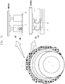
FIG. 9 is a view illustrating the structure of an antenna for a camera according to another example. - Specifically,
FIG. 9 illustrates an antenna for a camera that projects from one surface of thecamera body 23, which is surrounded by the metal, and is provided on the camera that includes the lens barrel having an injection-molded outer surface that is surrounded by metal. - The antenna for a camera illustrated in
FIG. 9 includes slitradiators lens barrel 40 and is spaced apart from the metal of thecamera body 23 by a predetermined distance. - The
slit radiators lens barrel 40 to mount the antenna, a radiation gain extension region of the antenna can be achieved. Theslit radiators - The
slit radiators power feeding portion 120 that feeds power to theslit radiator 100. Further, theslit radiator 100 may be connected to theground portion 140 that grounds theslit radiator 100 through thebody portion 23 of the camera. - One or
more slit radiators lens barrel 40 on the basis of the form exemplified inFIG. 10 , and may be spaced apart from each other by a predetermined distance if a plurality of slit radiators are provided as an example that is different from the form illustrated inFIG. 10 . Theslit radiators 100 may be implemented with different lengths and widths, and thus may be implemented as antennas having different resonance frequencies. -
FIG. 10 is a graph illustrating simulation results of the VSWR characteristics of a slit radiator according to an example. - Referring to
FIG. 10 , it is shown that theslit radiator FIG. 9 has a radiation pattern having the resonance frequency band of 1.5 GHz. - Although it is illustrated that the resonance frequency of the
slit radiators -
FIG. 11 is a graph illustrating the antenna radiation gain efficiencies of an antenna radiator according to an example versus an antenna radiator in the related art. - Referring to
FIG. 11 , it can be known that the radiators (a) and the slit radiator (b), provided along the extension direction of the lens insertion portion, and the lens barrel according to an example have a radiation gain efficiency that is quite higher than the radiation gain efficiency of the antennas (c) mounted on the bottom surface of the camera as in the related art. - Accordingly, the antenna according to an example can prevent the deterioration of the radiation gain efficiency caused by interference with other metal portions, and is implemented at a position where the antenna radio wave radiation is optimal to improve the radiation gain efficiency.
-
FIG. 12 is a view illustrating the fastening structure of an antenna for a camera, according to an example. - Referring to
FIG. 12 , the power feeding portion F and the ground portion G of the antenna may be formed on the camera using at least one of aspring 130, aC clip 140, and a soldering(not illustrated in the drawing). -
FIG. 13 is a view explaining a connection between a power feeding portion F and a ground portion G of an antenna for a camera and a circuit according to an example. - Accordingly,
FIG. 13 is a view explaining the connection between the power feeding portion F and the ground portion G and the circuit board after the power feeding portion F and the ground portion G, which are provided at one end of the radiator of the antenna through the configuration ofFIG. 12 , are connected to each other. - As exemplified in
FIG. 13 , a projection typepower feeding portion 162 is provided on thecircuit board 160 for power feeding to the antenna, and acable 170 that is connected to one end of the antenna may be configured in the form of asocket 180 into which the projection typepower feeding portion 162 can be inserted. - As exemplified in (a) of
FIG. 13 , thecable 170 having thesocket 180 may be fastened to thecircuit board 160, and as exemplified in (b) ofFIG. 13 , thecable 170 having thesocket 180 may be separated from thecircuit board 160. - Further, the projection type
power feeding portion 162 may also have a ground line. The ground line may be a portion having acylindrical pole shape 163 that surrounds the projection type outline. Accordingly, two different conductive lines are provided inside thecable 170. One conductive line may be a conductive line for power feeding, and the other conductive line may be a conductive line for grounding. Further, the respective conductive lines included in thecable 170 may be surrounded by an insulator. Further, two conductive lines surrounded by the insulator may be included in onecable 170. - As described above, the radiators having different structures are provided for the plurality of lens barrels that are detachably attached to the camera, and thus the antennas having different frequency bands can be selectively utilized by the camera.
- Further, by adjusting the length of the radiators provided in the extension direction of the lens barrel using the zoom-in function of the lens barrel, the resonance frequency of the antenna can be easily changed.
- Further, by grounding the antenna to the metal surrounding the camera body, the broadband characteristics of the antenna can be implemented.
- Still further, by implementing the antennas in the form of a slit that is spaced apart from the metal body by a predetermined distance, the deterioration of the radiation gain efficiency of the antenna caused by the interference with other metal parts can be prevented.
- It will be understood by those of ordinary skill in the art to which the present invention pertains that various changes in form and detail may be made therein without changing the technical idea or essential features of the present invention. Accordingly, it will be understood that the above-described embodiments do not limit the scope of the present invention. Accordingly, the scope of the present invention is defined by the appended claims, and it will be understood that all variations and modifications derived from the meanings and scope of the following claims and equivalent concepts fall within the scope of the present invention.
Claims (9)
- A camera with an antenna and a rotatable lens barrel (40), wherein the lens barrel (40) is rotatable into an extended position from the camera, the camera comprising a communication module provided therein, and the antenna comprising:a first radiator (34) provided in a predetermined position in at least a part of the circumference of a lens insertion portion of the camera, the first radiator (34) having a length and a width for receiving a signal from a first wireless communication system;a second radiator (42) provided in the lens barrel (40) of the camera, spaced apart from the first radiator (34) by a predetermined distance;a connector (44) provided in the lens barrel (40), a first end of the connector (44) connected to one end of the second radiator (42), wherein a second end of the connector (44) is configured to selectively contact the first radiator (34) according to rotation of the lens barrel (40), wherein the selective connection provides that a signal received from a second wireless communication system corresponds to the connection length of the first radiator (34) and the second radiator (42) and the widths of the respective radiators;a power feeding line (F) configured to feed a power from the communication module of the camera to the first radiator (34); anda ground line (G) configured to connect to and ground the first radiator (34).
- The camera of claim 1, wherein the lens barrel (40) is configured as a multi-stage structure and the cross-sectional area of the lens barrel (40) gradually narrows as the lens barrel (40) extends from the camera.
- The camera of claim 2, further comprising that the second radiator (42) is provided as a plurality of antennas, wherein each of the plurality of antennas is mounted at each stage of the lens barrel (40), and each of the antennas at a respective stage of the lens barrel successively come into contact with each other when the lens barrel is extended from the camera..
- The camera of claim 1, wherein the first radiator (34) is arranged in parallel to an object lens of the lens barrel (52).
- The camera of claim 1, wherein the second radiator (42) is arranged in the lens barrel (40) to be spaced apart for a predetermined distance from the first radiator (34) to provide a coupling signal to the first radiator (34).
- The camera of claim 5, wherein if the lens barrel (40) is configured in a multi-stage structure, the first radiator (34) and the second radiator (42) are arranged at different ends of the lens barrel (40).
- The camera of claim 6, wherein the first radiator (34) and second radiator (42) are arranged parallel, and the first radiator (34) is arranged in parallel to an object lens (52) of the lens barrel (40).
- The camera of any preceding claim, wherein the first radiator (34) is implemented as a Wi-Fi antenna, and when the second radiator (42) is connected to the first radiator (34), a length and a width of the second radiator (42) are set so that the second radiator operates as one of a Bluetooth, BT, antenna, a Global Positioning System, GPS, antenna, a Global System for Mobile communication, GSM, antenna, a Code Division Multiple Access, CDMA, antenna, a Wideband Code Division Multiple Access, WCDMA, antenna, and a diversity antenna.
- The camera of claim 1, wherein the first radiator (34) and second radiator (42) are arranged in parallel to an object lens (52) of the lens barrel (40).
Applications Claiming Priority (1)
| Application Number | Priority Date | Filing Date | Title |
|---|---|---|---|
| KR20130020827 | 2013-02-27 |
Publications (3)
| Publication Number | Publication Date |
|---|---|
| EP2772987A2 EP2772987A2 (en) | 2014-09-03 |
| EP2772987A3 EP2772987A3 (en) | 2014-12-03 |
| EP2772987B1 true EP2772987B1 (en) | 2019-07-03 |
Family
ID=50159131
Family Applications (1)
| Application Number | Title | Priority Date | Filing Date |
|---|---|---|---|
| EP14156785.9A Active EP2772987B1 (en) | 2013-02-27 | 2014-02-26 | Antenna for camera |
Country Status (4)
| Country | Link |
|---|---|
| US (1) | US9549103B2 (en) |
| EP (1) | EP2772987B1 (en) |
| KR (1) | KR102124634B1 (en) |
| CN (1) | CN104009280B (en) |
Families Citing this family (18)
| Publication number | Priority date | Publication date | Assignee | Title |
|---|---|---|---|---|
| KR102062904B1 (en) * | 2013-05-14 | 2020-01-07 | 삼성전자주식회사 | Digital camera |
| CN203932300U (en) * | 2014-05-29 | 2014-11-05 | 中兴通讯股份有限公司 | A kind of near field communication antenna device |
| USD808938S1 (en) * | 2014-10-20 | 2018-01-30 | Schneider Electric Industries Sas | RFID reader/writer device |
| KR20170106836A (en) * | 2016-03-14 | 2017-09-22 | 엘지전자 주식회사 | Image photographing apparatus |
| WO2017194078A1 (en) * | 2016-05-09 | 2017-11-16 | Sony Mobile Communications Inc | Surveillance system and method for camera-based surveillance |
| CN106058431B (en) * | 2016-07-27 | 2019-01-22 | 常熟市泓博通讯技术股份有限公司 | The module system of integral antenna |
| KR102267709B1 (en) * | 2017-03-24 | 2021-06-23 | 삼성전자주식회사 | Electronic device comprising antenna |
| CN109390675A (en) * | 2017-08-03 | 2019-02-26 | 泰科电子(上海)有限公司 | Antenna, emitter, reception device and wireless communication system |
| JP1612490S (en) * | 2018-01-29 | 2018-09-03 | ||
| CN108666737B (en) * | 2018-05-10 | 2021-06-15 | Oppo广东移动通信有限公司 | Electronic device |
| KR102604289B1 (en) * | 2018-11-28 | 2023-11-20 | 삼성전자주식회사 | Electronic device and antenna structure thereof |
| CN111370875B (en) * | 2018-12-25 | 2022-12-16 | 泰科电子(上海)有限公司 | Antenna, transmitting antenna, receiving antenna and wireless communication device |
| CN112448139B (en) * | 2019-08-30 | 2023-12-22 | Oppo广东移动通信有限公司 | Antenna assembly and electronic equipment |
| CN113904101B (en) * | 2020-06-22 | 2023-09-05 | 北京小米移动软件有限公司 | Terminal equipment and manufacturing method thereof |
| CN112164881B (en) * | 2020-09-23 | 2024-01-16 | 深圳市锐尔觅移动通信有限公司 | Camera decoration, antenna device and electronic equipment |
| CN113013619B (en) * | 2021-03-04 | 2022-10-28 | 杭州永谐科技有限公司上海分公司 | Structural design of low-cost open waveguide antenna |
| US11902664B2 (en) * | 2021-09-22 | 2024-02-13 | Adam A. Locke | Cellular telephone with protracting monitor screen and camera |
| WO2024043476A1 (en) * | 2022-08-22 | 2024-02-29 | 삼성전자주식회사 | Electronic device for adjusting, on basis of frequency, strength of data signal to be transmitted through conductive pattern, and method therefor |
Family Cites Families (30)
| Publication number | Priority date | Publication date | Assignee | Title |
|---|---|---|---|---|
| JP3788115B2 (en) * | 1999-07-23 | 2006-06-21 | 松下電器産業株式会社 | Method for manufacturing antenna device |
| US6677904B2 (en) * | 2002-01-31 | 2004-01-13 | Hewlett-Packard Development Company, L.P. | Integrated wireless antenna for an image capturing device |
| EP1359675B1 (en) * | 2002-05-02 | 2008-04-09 | Sony Ericsson Mobile Communications AB | Integrated antenna assembly |
| AU2003232221A1 (en) * | 2002-05-02 | 2003-11-17 | Sony Ericsson Mobile Communications Ab | Integrated antenna assembly |
| JP2004096341A (en) * | 2002-08-30 | 2004-03-25 | Fujitsu Ltd | Antenna apparatus including inverted f antenna with variable resonance frequency |
| US7119743B2 (en) * | 2003-06-09 | 2006-10-10 | Matsushita Electric Industrial Co., Ltd. | Antenna and electronic device using the same |
| JP2005345802A (en) * | 2004-06-03 | 2005-12-15 | Casio Comput Co Ltd | Imaging device, replacement unit used for the imaging device, and replacement unit use control method and program |
| JP2006135385A (en) * | 2004-11-02 | 2006-05-25 | Canon Inc | Camera |
| JP4897231B2 (en) * | 2005-03-23 | 2012-03-14 | コニカミノルタホールディングス株式会社 | The camera module |
| JP5098255B2 (en) | 2005-08-30 | 2012-12-12 | 株式会社ニコン | Wireless communication camera |
| US7653296B2 (en) * | 2005-08-30 | 2010-01-26 | Nikon Corporation | Camera and exchangeable lens barrel with wireless communication function |
| JP2007096421A (en) | 2005-09-27 | 2007-04-12 | Fujifilm Corp | Digital camera |
| KR100694876B1 (en) | 2006-02-09 | 2007-03-13 | 주식회사 엠씨넥스 | Camera module for antenna of communication device |
| JP4816171B2 (en) * | 2006-03-15 | 2011-11-16 | ソニー株式会社 | Electronic device, electronic device system, and communication method |
| KR101049572B1 (en) | 2006-08-09 | 2011-07-15 | 주식회사 엠씨넥스 | Dual Camera Module |
| US7369091B2 (en) * | 2006-08-31 | 2008-05-06 | Research In Motion Limited | Mobile wireless communications device having dual antenna system for cellular and WiFi |
| JP2008109216A (en) * | 2006-10-23 | 2008-05-08 | Olympus Corp | Electronic still camera |
| KR100842071B1 (en) * | 2006-12-18 | 2008-06-30 | 삼성전자주식회사 | Antenna system for concurrent mode |
| US7768462B2 (en) * | 2007-08-22 | 2010-08-03 | Apple Inc. | Multiband antenna for handheld electronic devices |
| TW200937108A (en) | 2008-01-18 | 2009-09-01 | Geotate Bv | Camera with satellite positioning system |
| US8436775B2 (en) * | 2009-01-14 | 2013-05-07 | Continental Automotive Systems, Inc. | Fakra-compliant antenna |
| US8599089B2 (en) * | 2010-03-30 | 2013-12-03 | Apple Inc. | Cavity-backed slot antenna with near-field-coupled parasitic slot |
| US8384614B2 (en) * | 2010-09-30 | 2013-02-26 | The United States Of America As Represented By The Administrator Of The National Aeronautics And Space Administration | Deployable wireless Fresnel lens |
| KR20120035311A (en) * | 2010-10-05 | 2012-04-16 | 삼성전자주식회사 | Antenna device for portable terminal |
| US8896488B2 (en) * | 2011-03-01 | 2014-11-25 | Apple Inc. | Multi-element antenna structure with wrapped substrate |
| KR101779457B1 (en) * | 2011-04-22 | 2017-09-19 | 삼성전자주식회사 | Antenna device for portable terminal |
| US8558906B2 (en) * | 2011-05-17 | 2013-10-15 | Prodigid Limited | Image capturing device having electromagnetic wave signal transmitting and receiving functions |
| KR20130057765A (en) * | 2011-11-24 | 2013-06-03 | 삼성전자주식회사 | Mobile electronic device and docking stage for the same |
| CN202615109U (en) * | 2012-06-04 | 2012-12-19 | 美细耐斯(上海)电子有限公司 | Camera module for antenna |
| KR102062904B1 (en) * | 2013-05-14 | 2020-01-07 | 삼성전자주식회사 | Digital camera |
-
2014
- 2014-02-26 EP EP14156785.9A patent/EP2772987B1/en active Active
- 2014-02-27 KR KR1020140023550A patent/KR102124634B1/en active IP Right Grant
- 2014-02-27 CN CN201410069159.9A patent/CN104009280B/en not_active Expired - Fee Related
- 2014-02-27 US US14/192,270 patent/US9549103B2/en not_active Expired - Fee Related
Non-Patent Citations (1)
| Title |
|---|
| None * |
Also Published As
| Publication number | Publication date |
|---|---|
| US20140240581A1 (en) | 2014-08-28 |
| US9549103B2 (en) | 2017-01-17 |
| CN104009280B (en) | 2018-10-26 |
| KR102124634B1 (en) | 2020-06-18 |
| EP2772987A2 (en) | 2014-09-03 |
| EP2772987A3 (en) | 2014-12-03 |
| KR20140107145A (en) | 2014-09-04 |
| CN104009280A (en) | 2014-08-27 |
Similar Documents
| Publication | Publication Date | Title |
|---|---|---|
| EP2772987B1 (en) | Antenna for camera | |
| TWI525904B (en) | Antenna structures having resonating elements and parasitic elements within slots in conductive elements | |
| EP3226348B1 (en) | Mobile terminal | |
| US9236650B2 (en) | Mobile terminal | |
| US7068227B2 (en) | Integrated antenna assembly | |
| KR102062904B1 (en) | Digital camera | |
| JP6139279B2 (en) | ANTENNA DEVICE AND ELECTRONIC DEVICE HAVING THE ANTENNA DEVICE | |
| US10916847B2 (en) | Multi-band antenna | |
| US20240072418A1 (en) | Antenna assembly and electronic device | |
| EP1359675A1 (en) | Integrated antenna assembly | |
| JP2010050548A (en) | Antenna device | |
| CN111384588B (en) | Multi-frequency antenna | |
| TWI663783B (en) | Antenna structure and wireless communication device with same | |
| KR20160080445A (en) | Internal antenna and portable terminal including the internal antenna | |
| TWI756931B (en) | Antenna structure | |
| WO2022183892A1 (en) | Antenna assembly and electronic device | |
| KR101850389B1 (en) | Mobile terminal | |
| CN117525847A (en) | Electronic equipment | |
| JP2010157834A (en) | Portable wireless apparatus |
Legal Events
| Date | Code | Title | Description |
|---|---|---|---|
| PUAI | Public reference made under article 153(3) epc to a published international application that has entered the european phase |
Free format text: ORIGINAL CODE: 0009012 |
|
| 17P | Request for examination filed |
Effective date: 20140226 |
|
| AK | Designated contracting states |
Kind code of ref document: A2 Designated state(s): AL AT BE BG CH CY CZ DE DK EE ES FI FR GB GR HR HU IE IS IT LI LT LU LV MC MK MT NL NO PL PT RO RS SE SI SK SM TR |
|
| AX | Request for extension of the european patent |
Extension state: BA ME |
|
| PUAL | Search report despatched |
Free format text: ORIGINAL CODE: 0009013 |
|
| AK | Designated contracting states |
Kind code of ref document: A3 Designated state(s): AL AT BE BG CH CY CZ DE DK EE ES FI FR GB GR HR HU IE IS IT LI LT LU LV MC MK MT NL NO PL PT RO RS SE SI SK SM TR |
|
| AX | Request for extension of the european patent |
Extension state: BA ME |
|
| RIC1 | Information provided on ipc code assigned before grant |
Ipc: H01Q 1/24 20060101ALI20141027BHEP Ipc: H01Q 9/14 20060101ALI20141027BHEP Ipc: H01Q 1/40 20060101AFI20141027BHEP Ipc: G03B 17/00 20060101ALI20141027BHEP Ipc: H01Q 9/42 20060101ALI20141027BHEP Ipc: H01Q 5/00 20060101ALI20141027BHEP Ipc: H01Q 13/10 20060101ALI20141027BHEP Ipc: H01Q 21/28 20060101ALI20141027BHEP |
|
| R17P | Request for examination filed (corrected) |
Effective date: 20150603 |
|
| STAA | Information on the status of an ep patent application or granted ep patent |
Free format text: STATUS: EXAMINATION IS IN PROGRESS |
|
| 17Q | First examination report despatched |
Effective date: 20170419 |
|
| GRAP | Despatch of communication of intention to grant a patent |
Free format text: ORIGINAL CODE: EPIDOSNIGR1 |
|
| STAA | Information on the status of an ep patent application or granted ep patent |
Free format text: STATUS: GRANT OF PATENT IS INTENDED |
|
| INTG | Intention to grant announced |
Effective date: 20190122 |
|
| GRAS | Grant fee paid |
Free format text: ORIGINAL CODE: EPIDOSNIGR3 |
|
| GRAA | (expected) grant |
Free format text: ORIGINAL CODE: 0009210 |
|
| STAA | Information on the status of an ep patent application or granted ep patent |
Free format text: STATUS: THE PATENT HAS BEEN GRANTED |
|
| AK | Designated contracting states |
Kind code of ref document: B1 Designated state(s): AL AT BE BG CH CY CZ DE DK EE ES FI FR GB GR HR HU IE IS IT LI LT LU LV MC MK MT NL NO PL PT RO RS SE SI SK SM TR |
|
| REG | Reference to a national code |
Ref country code: GB Ref legal event code: FG4D |
|
| REG | Reference to a national code |
Ref country code: CH Ref legal event code: EP Ref country code: AT Ref legal event code: REF Ref document number: 1152093 Country of ref document: AT Kind code of ref document: T Effective date: 20190715 |
|
| REG | Reference to a national code |
Ref country code: IE Ref legal event code: FG4D |
|
| REG | Reference to a national code |
Ref country code: DE Ref legal event code: R096 Ref document number: 602014049342 Country of ref document: DE |
|
| REG | Reference to a national code |
Ref country code: NL Ref legal event code: FP |
|
| REG | Reference to a national code |
Ref country code: LT Ref legal event code: MG4D |
|
| REG | Reference to a national code |
Ref country code: AT Ref legal event code: MK05 Ref document number: 1152093 Country of ref document: AT Kind code of ref document: T Effective date: 20190703 |
|
| PG25 | Lapsed in a contracting state [announced via postgrant information from national office to epo] |
Ref country code: FI Free format text: LAPSE BECAUSE OF FAILURE TO SUBMIT A TRANSLATION OF THE DESCRIPTION OR TO PAY THE FEE WITHIN THE PRESCRIBED TIME-LIMIT Effective date: 20190703 Ref country code: LT Free format text: LAPSE BECAUSE OF FAILURE TO SUBMIT A TRANSLATION OF THE DESCRIPTION OR TO PAY THE FEE WITHIN THE PRESCRIBED TIME-LIMIT Effective date: 20190703 Ref country code: BG Free format text: LAPSE BECAUSE OF FAILURE TO SUBMIT A TRANSLATION OF THE DESCRIPTION OR TO PAY THE FEE WITHIN THE PRESCRIBED TIME-LIMIT Effective date: 20191003 Ref country code: CZ Free format text: LAPSE BECAUSE OF FAILURE TO SUBMIT A TRANSLATION OF THE DESCRIPTION OR TO PAY THE FEE WITHIN THE PRESCRIBED TIME-LIMIT Effective date: 20190703 Ref country code: PT Free format text: LAPSE BECAUSE OF FAILURE TO SUBMIT A TRANSLATION OF THE DESCRIPTION OR TO PAY THE FEE WITHIN THE PRESCRIBED TIME-LIMIT Effective date: 20191104 Ref country code: NO Free format text: LAPSE BECAUSE OF FAILURE TO SUBMIT A TRANSLATION OF THE DESCRIPTION OR TO PAY THE FEE WITHIN THE PRESCRIBED TIME-LIMIT Effective date: 20191003 Ref country code: AT Free format text: LAPSE BECAUSE OF FAILURE TO SUBMIT A TRANSLATION OF THE DESCRIPTION OR TO PAY THE FEE WITHIN THE PRESCRIBED TIME-LIMIT Effective date: 20190703 Ref country code: HR Free format text: LAPSE BECAUSE OF FAILURE TO SUBMIT A TRANSLATION OF THE DESCRIPTION OR TO PAY THE FEE WITHIN THE PRESCRIBED TIME-LIMIT Effective date: 20190703 Ref country code: SE Free format text: LAPSE BECAUSE OF FAILURE TO SUBMIT A TRANSLATION OF THE DESCRIPTION OR TO PAY THE FEE WITHIN THE PRESCRIBED TIME-LIMIT Effective date: 20190703 |
|
| PG25 | Lapsed in a contracting state [announced via postgrant information from national office to epo] |
Ref country code: IS Free format text: LAPSE BECAUSE OF FAILURE TO SUBMIT A TRANSLATION OF THE DESCRIPTION OR TO PAY THE FEE WITHIN THE PRESCRIBED TIME-LIMIT Effective date: 20191103 Ref country code: RS Free format text: LAPSE BECAUSE OF FAILURE TO SUBMIT A TRANSLATION OF THE DESCRIPTION OR TO PAY THE FEE WITHIN THE PRESCRIBED TIME-LIMIT Effective date: 20190703 Ref country code: GR Free format text: LAPSE BECAUSE OF FAILURE TO SUBMIT A TRANSLATION OF THE DESCRIPTION OR TO PAY THE FEE WITHIN THE PRESCRIBED TIME-LIMIT Effective date: 20191004 Ref country code: LV Free format text: LAPSE BECAUSE OF FAILURE TO SUBMIT A TRANSLATION OF THE DESCRIPTION OR TO PAY THE FEE WITHIN THE PRESCRIBED TIME-LIMIT Effective date: 20190703 Ref country code: AL Free format text: LAPSE BECAUSE OF FAILURE TO SUBMIT A TRANSLATION OF THE DESCRIPTION OR TO PAY THE FEE WITHIN THE PRESCRIBED TIME-LIMIT Effective date: 20190703 Ref country code: ES Free format text: LAPSE BECAUSE OF FAILURE TO SUBMIT A TRANSLATION OF THE DESCRIPTION OR TO PAY THE FEE WITHIN THE PRESCRIBED TIME-LIMIT Effective date: 20190703 |
|
| PG25 | Lapsed in a contracting state [announced via postgrant information from national office to epo] |
Ref country code: TR Free format text: LAPSE BECAUSE OF FAILURE TO SUBMIT A TRANSLATION OF THE DESCRIPTION OR TO PAY THE FEE WITHIN THE PRESCRIBED TIME-LIMIT Effective date: 20190703 |
|
| PG25 | Lapsed in a contracting state [announced via postgrant information from national office to epo] |
Ref country code: EE Free format text: LAPSE BECAUSE OF FAILURE TO SUBMIT A TRANSLATION OF THE DESCRIPTION OR TO PAY THE FEE WITHIN THE PRESCRIBED TIME-LIMIT Effective date: 20190703 Ref country code: IT Free format text: LAPSE BECAUSE OF FAILURE TO SUBMIT A TRANSLATION OF THE DESCRIPTION OR TO PAY THE FEE WITHIN THE PRESCRIBED TIME-LIMIT Effective date: 20190703 Ref country code: DK Free format text: LAPSE BECAUSE OF FAILURE TO SUBMIT A TRANSLATION OF THE DESCRIPTION OR TO PAY THE FEE WITHIN THE PRESCRIBED TIME-LIMIT Effective date: 20190703 Ref country code: RO Free format text: LAPSE BECAUSE OF FAILURE TO SUBMIT A TRANSLATION OF THE DESCRIPTION OR TO PAY THE FEE WITHIN THE PRESCRIBED TIME-LIMIT Effective date: 20190703 Ref country code: PL Free format text: LAPSE BECAUSE OF FAILURE TO SUBMIT A TRANSLATION OF THE DESCRIPTION OR TO PAY THE FEE WITHIN THE PRESCRIBED TIME-LIMIT Effective date: 20190703 |
|
| PG25 | Lapsed in a contracting state [announced via postgrant information from national office to epo] |
Ref country code: SK Free format text: LAPSE BECAUSE OF FAILURE TO SUBMIT A TRANSLATION OF THE DESCRIPTION OR TO PAY THE FEE WITHIN THE PRESCRIBED TIME-LIMIT Effective date: 20190703 Ref country code: SM Free format text: LAPSE BECAUSE OF FAILURE TO SUBMIT A TRANSLATION OF THE DESCRIPTION OR TO PAY THE FEE WITHIN THE PRESCRIBED TIME-LIMIT Effective date: 20190703 Ref country code: IS Free format text: LAPSE BECAUSE OF FAILURE TO SUBMIT A TRANSLATION OF THE DESCRIPTION OR TO PAY THE FEE WITHIN THE PRESCRIBED TIME-LIMIT Effective date: 20200224 |
|
| REG | Reference to a national code |
Ref country code: DE Ref legal event code: R097 Ref document number: 602014049342 Country of ref document: DE |
|
| PLBE | No opposition filed within time limit |
Free format text: ORIGINAL CODE: 0009261 |
|
| STAA | Information on the status of an ep patent application or granted ep patent |
Free format text: STATUS: NO OPPOSITION FILED WITHIN TIME LIMIT |
|
| PG2D | Information on lapse in contracting state deleted |
Ref country code: IS |
|
| 26N | No opposition filed |
Effective date: 20200603 |
|
| PG25 | Lapsed in a contracting state [announced via postgrant information from national office to epo] |
Ref country code: SI Free format text: LAPSE BECAUSE OF FAILURE TO SUBMIT A TRANSLATION OF THE DESCRIPTION OR TO PAY THE FEE WITHIN THE PRESCRIBED TIME-LIMIT Effective date: 20190703 |
|
| REG | Reference to a national code |
Ref country code: CH Ref legal event code: PL |
|
| REG | Reference to a national code |
Ref country code: NL Ref legal event code: MM Effective date: 20200301 |
|
| REG | Reference to a national code |
Ref country code: BE Ref legal event code: MM Effective date: 20200229 |
|
| PG25 | Lapsed in a contracting state [announced via postgrant information from national office to epo] |
Ref country code: LU Free format text: LAPSE BECAUSE OF NON-PAYMENT OF DUE FEES Effective date: 20200226 Ref country code: MC Free format text: LAPSE BECAUSE OF FAILURE TO SUBMIT A TRANSLATION OF THE DESCRIPTION OR TO PAY THE FEE WITHIN THE PRESCRIBED TIME-LIMIT Effective date: 20190703 |
|
| PG25 | Lapsed in a contracting state [announced via postgrant information from national office to epo] |
Ref country code: LI Free format text: LAPSE BECAUSE OF NON-PAYMENT OF DUE FEES Effective date: 20200229 Ref country code: CH Free format text: LAPSE BECAUSE OF NON-PAYMENT OF DUE FEES Effective date: 20200229 |
|
| PG25 | Lapsed in a contracting state [announced via postgrant information from national office to epo] |
Ref country code: NL Free format text: LAPSE BECAUSE OF NON-PAYMENT OF DUE FEES Effective date: 20200301 |
|
| PG25 | Lapsed in a contracting state [announced via postgrant information from national office to epo] |
Ref country code: FR Free format text: LAPSE BECAUSE OF NON-PAYMENT OF DUE FEES Effective date: 20200229 Ref country code: IE Free format text: LAPSE BECAUSE OF NON-PAYMENT OF DUE FEES Effective date: 20200226 |
|
| PG25 | Lapsed in a contracting state [announced via postgrant information from national office to epo] |
Ref country code: BE Free format text: LAPSE BECAUSE OF NON-PAYMENT OF DUE FEES Effective date: 20200229 |
|
| PGFP | Annual fee paid to national office [announced via postgrant information from national office to epo] |
Ref country code: GB Payment date: 20220121 Year of fee payment: 9 Ref country code: DE Payment date: 20220120 Year of fee payment: 9 |
|
| PG25 | Lapsed in a contracting state [announced via postgrant information from national office to epo] |
Ref country code: MT Free format text: LAPSE BECAUSE OF FAILURE TO SUBMIT A TRANSLATION OF THE DESCRIPTION OR TO PAY THE FEE WITHIN THE PRESCRIBED TIME-LIMIT Effective date: 20190703 Ref country code: CY Free format text: LAPSE BECAUSE OF FAILURE TO SUBMIT A TRANSLATION OF THE DESCRIPTION OR TO PAY THE FEE WITHIN THE PRESCRIBED TIME-LIMIT Effective date: 20190703 |
|
| PG25 | Lapsed in a contracting state [announced via postgrant information from national office to epo] |
Ref country code: MK Free format text: LAPSE BECAUSE OF FAILURE TO SUBMIT A TRANSLATION OF THE DESCRIPTION OR TO PAY THE FEE WITHIN THE PRESCRIBED TIME-LIMIT Effective date: 20190703 |
|
| REG | Reference to a national code |
Ref country code: DE Ref legal event code: R119 Ref document number: 602014049342 Country of ref document: DE |
|
| GBPC | Gb: european patent ceased through non-payment of renewal fee |
Effective date: 20230226 |
|
| PG25 | Lapsed in a contracting state [announced via postgrant information from national office to epo] |
Ref country code: GB Free format text: LAPSE BECAUSE OF NON-PAYMENT OF DUE FEES Effective date: 20230226 |
|
| PG25 | Lapsed in a contracting state [announced via postgrant information from national office to epo] |
Ref country code: GB Free format text: LAPSE BECAUSE OF NON-PAYMENT OF DUE FEES Effective date: 20230226 Ref country code: DE Free format text: LAPSE BECAUSE OF NON-PAYMENT OF DUE FEES Effective date: 20230901 |