EP2772929A1 - Method for assembling discharge lamp and discharge lamp - Google Patents
Method for assembling discharge lamp and discharge lamp Download PDFInfo
- Publication number
- EP2772929A1 EP2772929A1 EP20120842935 EP12842935A EP2772929A1 EP 2772929 A1 EP2772929 A1 EP 2772929A1 EP 20120842935 EP20120842935 EP 20120842935 EP 12842935 A EP12842935 A EP 12842935A EP 2772929 A1 EP2772929 A1 EP 2772929A1
- Authority
- EP
- European Patent Office
- Prior art keywords
- holding
- discharge lamp
- ring portion
- burner
- outer tube
- Prior art date
- Legal status (The legal status is an assumption and is not a legal conclusion. Google has not performed a legal analysis and makes no representation as to the accuracy of the status listed.)
- Withdrawn
Links
Images


Classifications
-
- H—ELECTRICITY
- H01—ELECTRIC ELEMENTS
- H01J—ELECTRIC DISCHARGE TUBES OR DISCHARGE LAMPS
- H01J5/00—Details relating to vessels or to leading-in conductors common to two or more basic types of discharge tubes or lamps
- H01J5/48—Means forming part of the tube or lamp for the purpose of supporting it
-
- H—ELECTRICITY
- H01—ELECTRIC ELEMENTS
- H01J—ELECTRIC DISCHARGE TUBES OR DISCHARGE LAMPS
- H01J9/00—Apparatus or processes specially adapted for the manufacture, installation, removal, maintenance of electric discharge tubes, discharge lamps, or parts thereof; Recovery of material from discharge tubes or lamps
- H01J9/24—Manufacture or joining of vessels, leading-in conductors or bases
- H01J9/34—Joining base to vessel
Definitions
- Embodiments according to the present invention relate to a method of assembling a discharge lamp and the discharge lamp.
- a discharge lamp used for a head lamp of vehicles there is a known configuration in which a burner having a double-tube structure is held by a ring-shaped holder.
- the burner is inserted inside the ring-shaped holder, and an outer tube of the burner is held by a plurality of holding pieces extending to a central axis side of the holder.
- a discharge lamp with two different types of a light center length (LCL) standard and a method of assembling the same are to be provided by using a common burner and simplifying a structure.
- LCL light center length
- a method of assembling a discharge lamp which includes a burner including an inner tube including a light-emitting portion inside the inner tube, and an outer tube surrounding an outside of the inner tube; and a holder including a ring portion and a plurality of holding pieces.
- the ring portion includes a first surface having a reference protrusion and a second surface opposite to the first surface.
- the plurality of holding pieces extend from the ring portion to a central axis side of the ring portion.
- the holder holds the outer tube of the burner that is inserted inside the ring portion with a tip portion of the holding piece.
- a distance between a center of the light-emitting portion and the reference protrusion is changeable by selecting either one of a first holding position or a second holding position with respect to the one-type burner where a length of the inner tube and a length of the outer tube are made common with each other.
- the holding piece is inclined to the first surface side at a first angle with respect to a diametral direction of the ring portion and the tip portion of the holding piece protrudes to the first surface side to hold the outer tube at the first holding position.
- the holding piece is inclined to the second surface side at a second angle that is smaller than the first angle with respect to the diametral direction of the ring portion and the tip portion of the holding piece protrudes to the second surface side to hold the outer tube at the second holding position.
- Fig. 1 is a perspective view of a discharge lamp 1a of the embodiment
- Fig. 2 is a cross-sectional view of the discharge lamp 1a.
- the discharge lamp 1a of the embodiment is a high intensity discharge (HID) lamp used for a head lamp of vehicles and includes a burner 10 and a holder 30.
- HID high intensity discharge
- the embodiment will be described as designating a direction of the arrow F illustrated in Fig. 2 to be a front end side which becomes the front when the discharge lamp 1a is attached to a vehicle and a direction of the arrow B in the opposite direction thereof to be a rear end side.
- Fig. 3 is a perspective view of the burner 10 and the holder 30.
- Fig. 4 is a cross-sectional view of the burner 10.
- Fig. 5A is a plan view from the front end side of the burner 10 and the holder 30, and Fig. 5B is a plan view of a metal portion 41 of the holder 30.
- the burner 10 can be held at a first holding position by the holder 30, and the same burner 10 can be held at a second holding position by the holder 30.
- Figs. 1 to 3 illustrate the discharge lamp 1a with a second standard in which the burner 10 is held at the second holding position by the holder 30.
- a structure of the burner 10 held at the first holding position is the same as that held at the second holding position.
- the burner 10 has a double-tube structure including an inner tube 11 and an outer tube 12 that surrounds the outside of the inner tube 11.
- the inner tube 11 is formed of a material such as quartz glass having light-transmitting property and thermal resistance.
- a light-emitting portion 13 near the center of the inner tube 11 in a longitudinal direction (vertical direction in Fig. 4 ).
- plate-shaped sealing portions 16 at the both of ends of the light-emitting portion 13.
- cylinder portions 17a and 17b at ends on the opposite side of the light-emitting portion 13 in the sealing portions 16.
- the light-emitting portion 13, the sealing portions 16, and the cylinder portions 17a and 17b are integrally connected.
- the discharge medium 14 includes metal halide and a rare gas but does not include mercury so as to be a so-called mercury-free medium.
- Electrode mounts 21 are sealed in each of the sealing portions 16. As illustrated in Fig. 3 as well, the electrode mount 21 includes an electrode 22, a coil 23, a metal foil 24, and a lead wire 25.
- each of the pair of electrodes 22 faces each other inside the discharge space 14 as maintaining a predetermined distance between the electrodes.
- the coil 23 is wound around the electrode 22.
- the metal foil 24 connects the electrode 22 and the lead wire 25.
- An end portion of each of the pair of lead wires 25 extends to the outside of the inner tube 11.
- the lead wire 25 extending to the front end side of the burner 10 is connected with an end of a support wire 26 by laser welding, for example. That is, one of the pair of electrodes 22 facing the discharge space 14 is electrically connected to the support wire 26 through the electrode mount 21.
- a sleeve 27 formed of ceramic, for example, is mounted at a portion extending in parallel to a tube axis of a double-tube of the burner 10.
- the other of the pair of electrodes 22 is electrically connected to the lead wire 25 extending from the electrode mount 21 to the rear end side.
- the cylindrical-shaped outer tube 12 is provided concentrically with the inner tube 11 outside the inner tube 11.
- the outer tube 12 is welded in the vicinity of the cylinder portions 17a and 17b of the inner tube 11.
- a hermetically-sealed space 15 is formed between the inner tube 11 and the outer tube 12.
- a one-type gas or a mixed gas selected from neon, argon, xenon, and nitrogen is sealed in the space 15, for example.
- a material of the outer tube 12 be a material the thermal expansion coefficient of which is close to that of the inner tube 11 and which has a property of ultraviolet rays screening such as titanium, cerium, and quartz glass to which an oxide such as aluminum is added, for example.
- a pressure of the gas sealed in the inner space 15 of the outer tube 12 is lower than a gas pressure inside the discharge space 14 of the inner tube 11. Therefore, dielectric barrier discharge occurs in the inner space 15 of the outer tube 12 when starting lighting, thereby being spared from a dielectric breakdown. That is, it is possible to securely perform the light-emitting at a comparatively low discharge starting voltage.
- a metal band 55 illustrated in Figs. 1 to 3 is mounted on a farther rear end side than a light-emitting portion 13.
- the both of ends of the ring-shaped metal band 55 are welded to each other, and the metal band 55 is fixed on an outer peripheral surface of the outer tube 12.
- the holder 30 has a configuration in which a resin portion 31 and the metal portion 41 are assembled.
- the resin portion 31 has a ring portion 35 that is provided on an outer edge side of the holder 30.
- the ring portion 35 has a first surface and a second surface on the opposite side thereof. The first surface faces the front end side of the discharge lamp 1a and the second surface faces the rear end side of the discharge lamp 1a.
- a reference protrusion 33 protruding to the front end side on the first surface of the ring portion 35.
- a distance (D2 in Fig. 2 ) from a tip of the reference protrusion 33 to the center between the electrodes inside the light-emitting portion 13 is defined as a light center length (LCL) of the discharge lamp.
- Three outer peripheral side notches 32 are formed on an outer peripheral side of the ring portion 35, for example.
- Six inner peripheral side notches 34 are formed on an inner peripheral side of the ring portion 35, for example.
- the metal portion 41 of the holder 30 is a metal plate formed of stainless steel, for example. A portion of an outer peripheral side of the metal portion 41 is embedded in the resin portion 31 so that the metal portion 41 and the resin portion 31 are integrated with each other.
- Fig. 5B illustrates a planar shape of the metal portion 41 before being assembled with the resin portion 31.
- the metal portion 41 can be formed by punching a metal plate, for example.
- Fig. 5B illustrates a state in a plate shape after the punching and illustrates a state before bending is performed for the holding piece 43.
- the metal portion 41 has a ring portion 42 and a plurality of holding pieces 43 extending from the ring portion 42 to the central axis side of the ring portion 42.
- holding pieces 43 there are provided four holding pieces 43 at an interval of 90° on the ring portion 42 in the peripheral direction.
- a sleeve holding portion 44 on an inner peripheral side of the ring portion 42. There is provided the sleeve holding portion 44 between the holding pieces 43 that are adjacent to each other in the peripheral direction. A through hole 44a is formed in the sleeve holding portion 44, and the sleeve 27 of the burner 10 is inserted through the through hole 44a.
- Three notches 45 are formed on an outer peripheral side of the ring portion 42, for example.
- the notch 45 of the ring portion 42 of the metal portion 41 and the outer peripheral side notch 32 of the ring portion 35 of the resin portion 31 coincide with each other at a position in the peripheral direction, thereby assembling the metal portion 41 and the resin portion 31.
- Six slits 46 penetrating a front and a back of the ring portion 42 are formed in the ring portion 42 of the metal portion 41.
- the slit 46 and the inner peripheral side notch 34 formed on the resin portion 31 coincide with each other at a position in the peripheral direction, thereby assembling the metal portion 41 and the resin portion 31.
- the burner 10 is inserted inside the ring portion 42 of the metal portion 41 and held by the plurality of holding pieces 43 (four in the embodiment) .
- the burner 10 is held at the center position of the ring portion 42 in a state of being separated away from the ring portion 42.
- the burner 10 is held in a posture having the tube axis be in parallel to the central axis of the ring portion 42.
- Fig. 11B is a schematic cross-sectional view illustrating one of the sampled holding pieces 43.
- the ring portion 42 has a first surface 42a and a second surface 42b on the opposite side thereof.
- the first surface 42a faces the front end side and the second surface 42b faces the rear end side.
- a base portion of the ring portion 42 side in the holding piece 43 is bent toward the rear end side. That is, the holding piece 43 is inclined to the second surface 42b side with respect to the ring portion 42 in a diametric direction d, and a tip portion 43a of a holding portion 43 protrudes to the second surface 42b side. Furthermore, the tip portion 43a of the holding portion 43 is bent toward the rear end side and bonded by the laser welding with respect to the metal band 55, for example.
- the burner 10 is held at the second holding position by the holder 30.
- the metal band 55 that becomes a portion to be supported by the holding piece 43 in the burner 10 is positioned on a farther rear end side than the holder 30.
- the LCL (D2 in Fig. 2 ) is 18.0 mm, for example.
- the holding piece 43 is inclined to the second surface 42b side at a second angle ⁇ with respect to the ring portion 42 in the diametric direction d, and the tip portion 43a of the holding piece 43 is bonded to the metal band 55 on a farther rear end side than the second surface 42b.
- the second angle ⁇ is 40°, for example.
- a distance L2 between a base end portion 43b of the holding piece 43 embedded in the ring portion 42 and a bonding portion of the tip portion 43a and the metal band 55 is shorter than a corresponding distance L1 in a case of the first holding position described below.
- the base 50 is, for example, formed of an electrically conductive material and as illustrated in Fig. 6 , includes a housing 51 and a ring 52.
- a lighting circuit (not illustrated) and the like for starting and stably lighting the discharge lamp 1a are accommodated inside the housing 51.
- An end of the lead wire 25 extending to the rear end side and an end of the support wire 26 illustrated in Fig. 2 are connected to an end of the lighting circuit.
- an opening 54 that leads to the inside of the housing 51 is formed in an front end portion of the housing 51, and there is provided the ring 52 on a peripheral edge portion of the opening 54.
- protruding portions 53 are inserted into the slits 46 of the metal portion 41 of the holder 30 illustrated in Figs. 3 and 5(b) from the second surface side. As illustrated in Figs. 1 and 5(a) , the protruding portions 53 are bent toward the outer peripheral side of the holder 30. The bent protruding portions 53 are accommodated in the inner peripheral side notches 34 of the resin portion 31.
- the holder 30 is attached to the base 50.
- An overlapping portion of the bent protruding portion 53 and the metal portion 41 may be laser-welded, thereby bonding the protruding portion 53 to the metal portion 41. Otherwise, after inserting the protruding portion 53 into the slit 46, the protruding portion 53 may be bonded to the metal portion 41 by the welding without being bent.
- the discharge lamp is attached to a reflector 60.
- Every reflector 60 has a neck portion 61 having a hollow structure and a reflecting portion 62.
- a step difference is formed on an inner wall of the neck portion 61 on the rear end side, and there is provided an attachment surface 63 to which the holder 30 of the discharge lamp is attached on the rear end side of the neck portion 61.
- the attachment surface 63 is formed in an annular shape.
- engagement pieces 64 for example, on an inner peripheral wall of the neck portion 61 on a farther rear end side than the attachment surface 63.
- the reflecting portion 62 on the front end side of the neck portion 61 being connected to the neck portion 61.
- a lens holder 71 on a front end of the reflecting portion 62, and the lens holder 71 holds a lens 72.
- the burner 10 is inserted into the reflector 60 from the rear end side of the neck portion 61, thereby causing the first surface of the holder 30 to face the attachment surface 63.
- the notch 32 of the holder 30 and the engagement piece 64 coincide with each other at a position in the peripheral direction, thereby bringing the reference protrusion 33 into contact with the attachment surface 63.
- the whole base 50 of the discharge lamp is rotated with respect to the attachment surface 63, thereby interposing the resin portion 31 of the holder 30 between the attachment surface 63 and the engagement piece 64. Accordingly, the discharge lamp is fixed to the reflector 60.
- the burner 10 described above is held at the second holding position by the holder 30.
- the bending direction of the holding piece 43 in the holder 30 is set to be in the opposite direction of the second holding position, and thus, it is possible to hold the burner 10 at the first holding position.
- Fig. 8 is a perspective view of a discharge lamp 1b with a first standard in which the burner 10 is held at the first holding position by the holder 30.
- Fig. 9 is a cross-sectional view thereof.
- Fig. 10 is a perspective view of those burner 10 and holder 30.
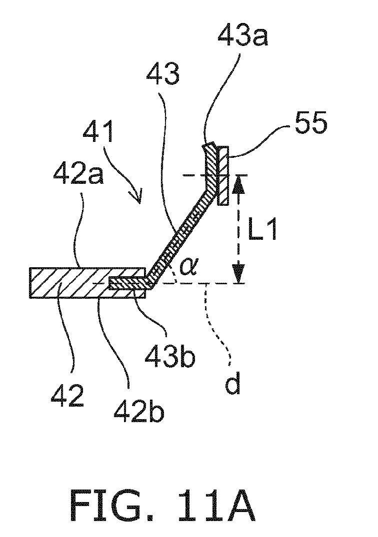
- Fig. 11A is a schematic cross-sectional view of one of the holding pieces 43 that holds the burner 10 at the first holding position being sampled and illustrated.
- the burner 10 is inserted into an inner side of the ring portion 42 of the metal portion 41, and held by four holding pieces 43.
- the burner 10 is held in a state of being separated away from the ring portion 42 at the center position of the ring portion 42.
- the burner 10 is held in the posture having the tube axis be in parallel to the central axis of the ring portion 42.
- the base portion of the ring portion 42 side in the holding piece 43 is bent toward the front end side that is the opposite side of the second holding position. That is, as illustrated in Fig. 11A , the holding piece 43 is inclined to the first surface 42a side with respect to the ring portion 42 in the diametric direction d, and the tip portion 43a of the holding portion 43 protrudes to the first surface 42a side. Furthermore, the tip portion 43a of the holding portion 43 is bent toward the front end side and bonded by the laser welding with respect to the metal band 55, for example.
- the metal band 55 that becomes a portion to be supported by the holding piece 43 in the burner 10 is positioned on a farther front end side than the holder 30.
- the LCL (D1 in Fig. 9 ) is 27.1 mm, for example.
- the holding piece 43 is inclined to the first surface 42a side at a first angle ⁇ with respect to the ring portion 42 in the diametric direction d, and the tip portion 43a of the holding piece 43 is bonded to the metal band 55 on a farther front end side than the first surface 42a.
- the first angle ⁇ is 55°, for example, which is larger than the second angle ⁇ in the case of the above-described second holding position.
- the distance L1 between the base end portion 43b of the holding piece 43 embedded in the ring portion 42 and the bonding portion of the tip portion 43a and the metal band 55 is 5 to 6 mm, for example, which is longer than the distance L2 in the case of the second holding position described above.
- This discharge lamp 1b also can be attached to the attachment surface 63 of the reflector 60 as similar to the above-described discharge lamp 1a.
- At least the burner 10 is the same in configuration and size.
- the discharge lamp 1a and the discharge lamp 1b differ depending on whether the burner 10 is held at the first holding position or at the second holding position by the holder 30.
- the LCL of the discharge lamp 1a (D2 in Fig. 2 ) and the LCL of the discharge lamp 1b (D1 in Fig. 9 ) differ from each other.
- the bending direction (protruding direction) of the holding piece 43 is reversed, it is possible to select either the first holding position or the second holding position. Then, in accordance with the difference of the holding position, it is possible to change the distance (LCL) between the center of the light-emitting portion 13 and the reference protrusion 33. That is, while using the one-type burner 10 the structure and the size of which are made common, it is possible to select and assemble the discharge lamp with two different types of the LCL standard by simply reversing the bending direction of the holding piece 43.
- the length and the thickness of the inner tube 11 are the same.
- the metal band 55 is mounted at the same position on the outer tube 12 in the longitudinal direction. That is, at the first holding position and the second holding position, the tip portion of the holding piece 43 holds the same position of the outer tube 12 in the longitudinal direction.
- the length of the sleeve 27 is the same as each other.
- the length of the support wire 26 may be the same as or different from each other in the discharge lamp 1b and the discharge lamp 1a.
- the length of the lead wire 25 also may be the same as or different from each other in the discharge lamp 1b and the discharge lamp 1a.
- efficiency in manufacturing and a reduction in costs can be achieved by making components common such as using the burner 10 of the same type and the same standard. That is, there is no need to individually manufacture or prepare burners in accordance with the difference of the LCL. It is possible to easily manage either of the discharge lamps in two different types of LCL standard by making the burner 10 common and processing the holding piece 43. As a result, it is possible to provide an inexpensive discharge lamp.
- the LCL of which is 27.1 mm illustrated in Figs. 8 to 10 even if the holding piece 43 is simply bent toward the rear end side to hold the burner 10, it is not possible to set the LCL to be 18.0 mm.
- the bent angle (inclined angle) ⁇ of the holding piece 43 when being at the second holding position is set to be smaller than the bent angle (inclined angle) ⁇ of the holding piece 43 when being at the first holding position.
- the metal portion 41 of the holder 30 by punching a sheet of metal plate, for example. Accordingly, as illustrated in Fig. 5B , the plurality of holding pieces 43 can be integrally molded, and thus, it is possible to reduce the number of components.
- the holder 30 may be configured only of a metal.
- the structure of the holder 30 does not have to be completely the same.
- a holder 80 illustrated in Fig. 12 has the ring-shaped resin portion 82 and a plurality of holding pieces 81 one end portion of which is embedded in the resin portion 82 and the other end portion (tip portion) of which extends toward the metal band 55 to be bonded thereto.
- a sleeve holding portion 83 on an inner peripheral side of the resin portion 82 in the holder 80.
- a base 91 may be a socket-type that has no lighting circuit therein.
Landscapes
- Engineering & Computer Science (AREA)
- Manufacturing & Machinery (AREA)
- Common Detailed Techniques For Electron Tubes Or Discharge Tubes (AREA)
- Non-Portable Lighting Devices Or Systems Thereof (AREA)
- Manufacture Of Electron Tubes, Discharge Lamp Vessels, Lead-In Wires, And The Like (AREA)
Abstract
Description
- Embodiments according to the present invention relate to a method of assembling a discharge lamp and the discharge lamp.
- For example, as a discharge lamp used for a head lamp of vehicles, there is a known configuration in which a burner having a double-tube structure is held by a ring-shaped holder. The burner is inserted inside the ring-shaped holder, and an outer tube of the burner is held by a plurality of holding pieces extending to a central axis side of the holder.
- [PTL 1] Pamphlet of International Publication No.
WO 2011/033417 - A discharge lamp with two different types of a light center length (LCL) standard and a method of assembling the same are to be provided by using a common burner and simplifying a structure.
- According to embodiments, there is provided a method of assembling a discharge lamp which includes a burner including an inner tube including a light-emitting portion inside the inner tube, and an outer tube surrounding an outside of the inner tube; and a holder including a ring portion and a plurality of holding pieces. The ring portion includes a first surface having a reference protrusion and a second surface opposite to the first surface. The plurality of holding pieces extend from the ring portion to a central axis side of the ring portion. The holder holds the outer tube of the burner that is inserted inside the ring portion with a tip portion of the holding piece. According to the method of assembling a discharge lamp, a distance between a center of the light-emitting portion and the reference protrusion is changeable by selecting either one of a first holding position or a second holding position with respect to the one-type burner where a length of the inner tube and a length of the outer tube are made common with each other. The holding piece is inclined to the first surface side at a first angle with respect to a diametral direction of the ring portion and the tip portion of the holding piece protrudes to the first surface side to hold the outer tube at the first holding position. And the holding piece is inclined to the second surface side at a second angle that is smaller than the first angle with respect to the diametral direction of the ring portion and the tip portion of the holding piece protrudes to the second surface side to hold the outer tube at the second holding position.
-
- [
Fig. 1 Fig. 1 is a perspective view of a discharge lamp according to an embodiment, and the discharge lamp in the perspective view includes a burner held at a second holding position by a holder. - [
Fig. 2] Fig. 2 is a cross-sectional view of the discharge lamp inFig. 1 . - [
Fig. 3] Fig. 3 is a perspective view of the burner and the holder of the discharge lamp inFig. 1 . - [
Fig. 4] Fig. 4 is a cross-sectional view of the burner according to the embodiment. - [
Fig. 5] Fig. 5A is a plan view of the holder according to the embodiment, andFig. 5B is a plan view of a metal portion of the holder. - [
Fig. 6] Fig. 6 is a perspective view of a base according to the embodiment. - [
Fig. 7] Fig. 7A is a perspective view illustrating the appearance of a reflector according to the embodiment, andFig. 7B is a cross-sectional view of the reflector. - [
Fig. 8] Fig. 8 is a perspective view of the discharge lamp according to the embodiment, and the discharge lamp in the perspective view includes the burner held at a first holding position by the holder. - [
Fig. 9] Fig. 9 is a cross-sectional view of the discharge lamp inFig. 8 . - [
Fig. 10] Fig. 10 is a perspective view of the burner and the holder of the discharge lamp inFig. 8 . - [
Fig. 11] Fig. 11A is a schematic cross-sectional view of one of holding pieces that holds the burner at the first holding position being sampled and illustrated, andFig. 11B is a schematic cross-sectional view of one of the holding pieces that holds the burner at the second holding position being sampled and illustrated. - [
Fig. 12] Fig. 12 is a perspective view of the discharge lamp according to another embodiment in which the burner is held at the first holding position by the holder. Description of Embodiments - Hereinafter, with reference to the drawings, embodiments will be described. In each drawing, the same reference numerals and signs are applied to the same elements.
-
Fig. 1 is a perspective view of adischarge lamp 1a of the embodiment, andFig. 2 is a cross-sectional view of thedischarge lamp 1a. - For example, the
discharge lamp 1a of the embodiment is a high intensity discharge (HID) lamp used for a head lamp of vehicles and includes aburner 10 and aholder 30. In addition, the embodiment will be described as designating a direction of the arrow F illustrated inFig. 2 to be a front end side which becomes the front when thedischarge lamp 1a is attached to a vehicle and a direction of the arrow B in the opposite direction thereof to be a rear end side. -
Fig. 3 is a perspective view of theburner 10 and theholder 30. -
Fig. 4 is a cross-sectional view of theburner 10. -
Fig. 5A is a plan view from the front end side of theburner 10 and theholder 30, andFig. 5B is a plan view of ametal portion 41 of theholder 30. - As described below, according to the embodiment, the
burner 10 can be held at a first holding position by theholder 30, and thesame burner 10 can be held at a second holding position by theholder 30. -
Figs. 1 to 3 illustrate thedischarge lamp 1a with a second standard in which theburner 10 is held at the second holding position by theholder 30. A structure of theburner 10 held at the first holding position is the same as that held at the second holding position. - The
burner 10 has a double-tube structure including aninner tube 11 and anouter tube 12 that surrounds the outside of theinner tube 11. For example, theinner tube 11 is formed of a material such as quartz glass having light-transmitting property and thermal resistance. - There is provided a light-emitting
portion 13 near the center of theinner tube 11 in a longitudinal direction (vertical direction inFig. 4 ). There are provided plate-shaped sealing portions 16 at the both of ends of the light-emittingportion 13. Furthermore, there are providedcylinder portions portion 13 in thesealing portions 16. The light-emittingportion 13, thesealing portions 16, and thecylinder portions - There is formed a
discharge space 14 inside the light-emittingportion 13. A discharge medium is sealed in thedischarge space 14. For example, thedischarge medium 14 includes metal halide and a rare gas but does not include mercury so as to be a so-called mercury-free medium. - There is provided a pair of sealing
portions 16 interposing the light-emittingportion 13 therebetween.Electrode mounts 21 are sealed in each of the sealingportions 16. As illustrated inFig. 3 as well, theelectrode mount 21 includes anelectrode 22, acoil 23, ametal foil 24, and alead wire 25. - An end of each of the pair of
electrodes 22 faces each other inside thedischarge space 14 as maintaining a predetermined distance between the electrodes. Thecoil 23 is wound around theelectrode 22. - The
metal foil 24 connects theelectrode 22 and thelead wire 25. An end portion of each of the pair oflead wires 25 extends to the outside of theinner tube 11. Therebetween, thelead wire 25 extending to the front end side of theburner 10 is connected with an end of asupport wire 26 by laser welding, for example. That is, one of the pair ofelectrodes 22 facing thedischarge space 14 is electrically connected to thesupport wire 26 through theelectrode mount 21. In thesupport wire 26, asleeve 27 formed of ceramic, for example, is mounted at a portion extending in parallel to a tube axis of a double-tube of theburner 10. - The other of the pair of
electrodes 22 is electrically connected to thelead wire 25 extending from theelectrode mount 21 to the rear end side. - The cylindrical-shaped
outer tube 12 is provided concentrically with theinner tube 11 outside theinner tube 11. Theouter tube 12 is welded in the vicinity of thecylinder portions inner tube 11. A hermetically-sealedspace 15 is formed between theinner tube 11 and theouter tube 12. A one-type gas or a mixed gas selected from neon, argon, xenon, and nitrogen is sealed in thespace 15, for example. It is preferable that a material of theouter tube 12 be a material the thermal expansion coefficient of which is close to that of theinner tube 11 and which has a property of ultraviolet rays screening such as titanium, cerium, and quartz glass to which an oxide such as aluminum is added, for example. - A pressure of the gas sealed in the
inner space 15 of theouter tube 12 is lower than a gas pressure inside thedischarge space 14 of theinner tube 11. Therefore, dielectric barrier discharge occurs in theinner space 15 of theouter tube 12 when starting lighting, thereby being spared from a dielectric breakdown. That is, it is possible to securely perform the light-emitting at a comparatively low discharge starting voltage. - In the
burner 10, ametal band 55 illustrated inFigs. 1 to 3 is mounted on a farther rear end side than a light-emittingportion 13. The both of ends of the ring-shapedmetal band 55 are welded to each other, and themetal band 55 is fixed on an outer peripheral surface of theouter tube 12. - There is provided the
holder 30 around themetal band 55. Theholder 30 has a configuration in which aresin portion 31 and themetal portion 41 are assembled. - As illustrated in
Fig. 5A , theresin portion 31 has aring portion 35 that is provided on an outer edge side of theholder 30. Thering portion 35 has a first surface and a second surface on the opposite side thereof. The first surface faces the front end side of thedischarge lamp 1a and the second surface faces the rear end side of thedischarge lamp 1a. - There is provided a
reference protrusion 33 protruding to the front end side on the first surface of thering portion 35. For example, there are provided threereference protrusions 33 at an interval of 120° on thering portion 35 in a peripheral direction. - In a state where the
burner 10 is held by theholder 30, a distance (D2 inFig. 2 ) from a tip of thereference protrusion 33 to the center between the electrodes inside the light-emittingportion 13 is defined as a light center length (LCL) of the discharge lamp. - Three outer
peripheral side notches 32 are formed on an outer peripheral side of thering portion 35, for example. Six innerperipheral side notches 34 are formed on an inner peripheral side of thering portion 35, for example. - The
metal portion 41 of theholder 30 is a metal plate formed of stainless steel, for example. A portion of an outer peripheral side of themetal portion 41 is embedded in theresin portion 31 so that themetal portion 41 and theresin portion 31 are integrated with each other. -
Fig. 5B illustrates a planar shape of themetal portion 41 before being assembled with theresin portion 31. Themetal portion 41 can be formed by punching a metal plate, for example.Fig. 5B illustrates a state in a plate shape after the punching and illustrates a state before bending is performed for the holdingpiece 43. - The
metal portion 41 has aring portion 42 and a plurality of holdingpieces 43 extending from thering portion 42 to the central axis side of thering portion 42. For example, there are provided four holdingpieces 43 at an interval of 90° on thering portion 42 in the peripheral direction. - There is provided a
sleeve holding portion 44 on an inner peripheral side of thering portion 42. There is provided thesleeve holding portion 44 between the holdingpieces 43 that are adjacent to each other in the peripheral direction. A throughhole 44a is formed in thesleeve holding portion 44, and thesleeve 27 of theburner 10 is inserted through the throughhole 44a. - Three
notches 45 are formed on an outer peripheral side of thering portion 42, for example. Thenotch 45 of thering portion 42 of themetal portion 41 and the outerperipheral side notch 32 of thering portion 35 of theresin portion 31 coincide with each other at a position in the peripheral direction, thereby assembling themetal portion 41 and theresin portion 31. - Six
slits 46 penetrating a front and a back of thering portion 42 are formed in thering portion 42 of themetal portion 41. Theslit 46 and the innerperipheral side notch 34 formed on theresin portion 31 coincide with each other at a position in the peripheral direction, thereby assembling themetal portion 41 and theresin portion 31. - As illustrated in
Figs. 1 to 3 , theburner 10 is inserted inside thering portion 42 of themetal portion 41 and held by the plurality of holding pieces 43 (four in the embodiment) . Theburner 10 is held at the center position of thering portion 42 in a state of being separated away from thering portion 42. Theburner 10 is held in a posture having the tube axis be in parallel to the central axis of thering portion 42. -
Fig. 11B is a schematic cross-sectional view illustrating one of the sampled holdingpieces 43. Thering portion 42 has afirst surface 42a and asecond surface 42b on the opposite side thereof. Thefirst surface 42a faces the front end side and thesecond surface 42b faces the rear end side. - A base portion of the
ring portion 42 side in the holdingpiece 43 is bent toward the rear end side. That is, the holdingpiece 43 is inclined to thesecond surface 42b side with respect to thering portion 42 in a diametric direction d, and atip portion 43a of a holdingportion 43 protrudes to thesecond surface 42b side. Furthermore, thetip portion 43a of the holdingportion 43 is bent toward the rear end side and bonded by the laser welding with respect to themetal band 55, for example. - In
Figs. 1 to 3 , theburner 10 is held at the second holding position by theholder 30. As illustrated inFig. 2 , at the second holding position, themetal band 55 that becomes a portion to be supported by the holdingpiece 43 in theburner 10 is positioned on a farther rear end side than theholder 30. In a case of the second holding position, the LCL (D2 inFig. 2 ) is 18.0 mm, for example. - As illustrated in
Fig. 11B , the holdingpiece 43 is inclined to thesecond surface 42b side at a second angle β with respect to thering portion 42 in the diametric direction d, and thetip portion 43a of the holdingpiece 43 is bonded to themetal band 55 on a farther rear end side than thesecond surface 42b. The second angle β is 40°, for example. - In addition, a distance L2 between a
base end portion 43b of the holdingpiece 43 embedded in thering portion 42 and a bonding portion of thetip portion 43a and themetal band 55 is shorter than a corresponding distance L1 in a case of the first holding position described below. - As illustrated in
Figs. 1 and2 , there is provided abase 50 on the rear end side of theholder 30. Thebase 50 is, for example, formed of an electrically conductive material and as illustrated inFig. 6 , includes ahousing 51 and aring 52. - Inside the
housing 51, a lighting circuit (not illustrated) and the like for starting and stably lighting thedischarge lamp 1a are accommodated. An end of thelead wire 25 extending to the rear end side and an end of thesupport wire 26 illustrated inFig. 2 are connected to an end of the lighting circuit. - As illustrated in
Fig. 6 , anopening 54 that leads to the inside of thehousing 51 is formed in an front end portion of thehousing 51, and there is provided thering 52 on a peripheral edge portion of theopening 54. There are provided six protrudingportions 53, for example, on the front end side of thering 52. - These protruding
portions 53 are inserted into theslits 46 of themetal portion 41 of theholder 30 illustrated inFigs. 3 and5(b) from the second surface side. As illustrated inFigs. 1 and5(a) , the protrudingportions 53 are bent toward the outer peripheral side of theholder 30. The bent protrudingportions 53 are accommodated in the innerperipheral side notches 34 of theresin portion 31. - Accordingly, the
holder 30 is attached to thebase 50. An overlapping portion of the bent protrudingportion 53 and themetal portion 41 may be laser-welded, thereby bonding the protrudingportion 53 to themetal portion 41. Otherwise, after inserting the protrudingportion 53 into theslit 46, the protrudingportion 53 may be bonded to themetal portion 41 by the welding without being bent. - As illustrated in
Figs. 7 (a) and 7 (b) , the discharge lamp is attached to areflector 60. Everyreflector 60 has aneck portion 61 having a hollow structure and a reflectingportion 62. - A step difference is formed on an inner wall of the
neck portion 61 on the rear end side, and there is provided anattachment surface 63 to which theholder 30 of the discharge lamp is attached on the rear end side of theneck portion 61. As illustrated inFig. 7A , theattachment surface 63 is formed in an annular shape. There are provided threeengagement pieces 64, for example, on an inner peripheral wall of theneck portion 61 on a farther rear end side than theattachment surface 63. - There is provided the reflecting
portion 62 on the front end side of theneck portion 61 being connected to theneck portion 61. There is provided alens holder 71 on a front end of the reflectingportion 62, and thelens holder 71 holds alens 72. - The
burner 10 is inserted into thereflector 60 from the rear end side of theneck portion 61, thereby causing the first surface of theholder 30 to face theattachment surface 63. Thenotch 32 of theholder 30 and theengagement piece 64 coincide with each other at a position in the peripheral direction, thereby bringing thereference protrusion 33 into contact with theattachment surface 63. Then, thewhole base 50 of the discharge lamp is rotated with respect to theattachment surface 63, thereby interposing theresin portion 31 of theholder 30 between theattachment surface 63 and theengagement piece 64. Accordingly, the discharge lamp is fixed to thereflector 60. - The
burner 10 described above is held at the second holding position by theholder 30. However, the bending direction of the holdingpiece 43 in theholder 30 is set to be in the opposite direction of the second holding position, and thus, it is possible to hold theburner 10 at the first holding position. -
Fig. 8 is a perspective view of adischarge lamp 1b with a first standard in which theburner 10 is held at the first holding position by theholder 30.Fig. 9 is a cross-sectional view thereof.Fig. 10 is a perspective view of thoseburner 10 andholder 30.Fig. 11A is a schematic cross-sectional view of one of the holdingpieces 43 that holds theburner 10 at the first holding position being sampled and illustrated. - The
burner 10 is inserted into an inner side of thering portion 42 of themetal portion 41, and held by four holdingpieces 43. Theburner 10 is held in a state of being separated away from thering portion 42 at the center position of thering portion 42. Theburner 10 is held in the posture having the tube axis be in parallel to the central axis of thering portion 42. - The base portion of the
ring portion 42 side in the holdingpiece 43 is bent toward the front end side that is the opposite side of the second holding position. That is, as illustrated inFig. 11A , the holdingpiece 43 is inclined to thefirst surface 42a side with respect to thering portion 42 in the diametric direction d, and thetip portion 43a of the holdingportion 43 protrudes to thefirst surface 42a side. Furthermore, thetip portion 43a of the holdingportion 43 is bent toward the front end side and bonded by the laser welding with respect to themetal band 55, for example. - At the first holding position, the
metal band 55 that becomes a portion to be supported by the holdingpiece 43 in theburner 10 is positioned on a farther front end side than theholder 30. In a case of the first holding position, the LCL (D1 inFig. 9 ) is 27.1 mm, for example. - As illustrated in
Fig. 11A , the holdingpiece 43 is inclined to thefirst surface 42a side at a first angle α with respect to thering portion 42 in the diametric direction d, and thetip portion 43a of the holdingpiece 43 is bonded to themetal band 55 on a farther front end side than thefirst surface 42a. The first angle α is 55°, for example, which is larger than the second angle β in the case of the above-described second holding position. - In addition, the distance L1 between the
base end portion 43b of the holdingpiece 43 embedded in thering portion 42 and the bonding portion of thetip portion 43a and themetal band 55 is 5 to 6 mm, for example, which is longer than the distance L2 in the case of the second holding position described above. - This
discharge lamp 1b also can be attached to theattachment surface 63 of thereflector 60 as similar to the above-describeddischarge lamp 1a. - In the
discharge lamp 1b with the first standard illustrated inFigs. 8 to 10 and thedischarge lamp 1a with the second standard illustrated inFigs. 1 to 3 , at least theburner 10 is the same in configuration and size. - The
discharge lamp 1a and thedischarge lamp 1b differ depending on whether theburner 10 is held at the first holding position or at the second holding position by theholder 30. In accordance with the difference of the holding position, the LCL of thedischarge lamp 1a (D2 inFig. 2 ) and the LCL of thedischarge lamp 1b (D1 inFig. 9 ) differ from each other. - According to the embodiment, if the bending direction (protruding direction) of the holding
piece 43 is reversed, it is possible to select either the first holding position or the second holding position. Then, in accordance with the difference of the holding position, it is possible to change the distance (LCL) between the center of the light-emittingportion 13 and thereference protrusion 33. That is, while using the one-type burner 10 the structure and the size of which are made common, it is possible to select and assemble the discharge lamp with two different types of the LCL standard by simply reversing the bending direction of the holdingpiece 43. - In the
discharge lamp 1b with the LCL of D1 and thedischarge lamp 1a with the LCL of D2 (< D1), the length and the thickness of theinner tube 11, the sealed gas inside thedischarge space 14, the length and the thickness of theouter tube 12, and the sealed gas inside thespace 15 are the same. - In addition, in the
discharge lamp 1b and thedischarge lamp 1a, themetal band 55 is mounted at the same position on theouter tube 12 in the longitudinal direction. That is, at the first holding position and the second holding position, the tip portion of the holdingpiece 43 holds the same position of theouter tube 12 in the longitudinal direction. - In addition, in the
discharge lamp 1b and thedischarge lamp 1a, the length of thesleeve 27 is the same as each other. The length of thesupport wire 26 may be the same as or different from each other in thedischarge lamp 1b and thedischarge lamp 1a. The length of thelead wire 25 also may be the same as or different from each other in thedischarge lamp 1b and thedischarge lamp 1a. - According to the embodiment, efficiency in manufacturing and a reduction in costs can be achieved by making components common such as using the
burner 10 of the same type and the same standard. That is, there is no need to individually manufacture or prepare burners in accordance with the difference of the LCL. It is possible to easily manage either of the discharge lamps in two different types of LCL standard by making theburner 10 common and processing the holdingpiece 43. As a result, it is possible to provide an inexpensive discharge lamp. - For example, the LCL of the
discharge lamp 1b with the first standard (= D1) is 27.1 mm, and the LCL of thedischarge lamp 1a with the second standard (= D2) is 18.0 mm. - Here, in the
discharge lamp 1b the LCL of which is 27.1 mm illustrated inFigs. 8 to 10 , even if the holdingpiece 43 is simply bent toward the rear end side to hold theburner 10, it is not possible to set the LCL to be 18.0 mm. Thedischarge lamp 1b the LCL of which is 27.1 mm has a distance L1 inFig. 11A of 5 to 6 mm, for example. If the holdingpiece 43 is bent (inclined) toward the rear end side at the same angle α, a distance L2 inFig. 11B becomes the same as the L1 (for example, 5 to 6 mm), thereby causing the LCL (= D2) to be equal to or less than 18 mm. - Therefore, according to the embodiment, the bent angle (inclined angle) β of the holding
piece 43 when being at the second holding position is set to be smaller than the bent angle (inclined angle) α of the holdingpiece 43 when being at the first holding position. For example, the angle β is set to be 40° with respect to the angle α of 55°, and thus, it is possible to adjust the LCL (= D2) to be 18.0 mm. - In addition, while being α > β, it is possible to overlap the
tip portion 43a of the holdingpiece 43 with themetal band 55 at the same position by appropriately setting each of the angles α, and β, and thus, it is easy to perform the welding event if the holding position varies. - In
discharge lamp 1a the bent angle β of which is relatively small, compared to thedischarge lamp 1b the bent angle α of which is relatively large, holding strength of theburner 10 becomes high, thereby being excellent in a deflection characteristic (being difficult to be displaced). - It is possible to acquire the
metal portion 41 of theholder 30 by punching a sheet of metal plate, for example. Accordingly, as illustrated inFig. 5B , the plurality of holdingpieces 43 can be integrally molded, and thus, it is possible to reduce the number of components. - Without being limited to a configuration of assembling the
resin portion 31 and themetal portion 41, theholder 30 may be configured only of a metal. In addition, in thedischarge lamp 1b and thedischarge lamp 1a, the structure of theholder 30 does not have to be completely the same. - In addition, for example, as illustrated in
Fig. 12 , fourindependent holding pieces 81 may be incorporated with aresin portion 82. That is, aholder 80 illustrated inFig. 12 has the ring-shapedresin portion 82 and a plurality of holdingpieces 81 one end portion of which is embedded in theresin portion 82 and the other end portion (tip portion) of which extends toward themetal band 55 to be bonded thereto. In addition, there is provided asleeve holding portion 83 on an inner peripheral side of theresin portion 82 in theholder 80. - In addition, as illustrated in
Fig. 12 , abase 91 may be a socket-type that has no lighting circuit therein. - While certain embodiments have been described, these embodiments have been presented by way of example only, and are not intended to limit the scope of the inventions. Indeed, the novel embodiments described herein may be embodied in a variety of other forms; furthermore, various omissions, substitutions and changes in the form of the embodiments described herein may be made without departing from the spirit of the inventions. The accompanying claims and their equivalents are intended to cover such forms or modifications as would fall within the scope and spirit of the inventions.
Claims (3)
- A method of assembling a discharge lamp which comprises
a burner including an inner tube including a light-emitting portion inside the inner tube, and an outer tube surrounding an outside of the inner tube; and
a holder including a ring portion and a plurality of holding pieces, the ring portion including a first surface having a reference protrusion and a second surface opposite to the first surface, the plurality of holding pieces extending from the ring portion to a central axis side of the ring portion, the holder holding the outer tube of the burner that is inserted inside the ring portion with a tip portion of the holding piece,
wherein a distance between a center of the light-emitting portion and the reference protrusion is changeable by selecting either one of a first holding position or a second holding position with respect to the one-type burner where a length of the inner tube and a length of the outer tube are made common with each other,
while the holding piece is inclined to the first surface side at a first angle with respect to a diametral direction of the ring portion and the tip portion of the holding piece protrudes to the first surface side to hold the outer tube at the first holding position, and the holding piece is inclined to the second surface side at a second angle that is smaller than the first angle with respect to the diametral direction of the ring portion and the tip portion of the holding piece protrudes to the second surface side to hold the outer tube at the second holding position. - The method of assembling a discharge lamp according to claim 1,
wherein at the first holding position and the second holding position, the tip portion of the holding piece holds the outer tube at the same position in a longitudinal direction. - A discharge lamp comprising:a burner including an inner tube including a light-emitting portion inside the inner tube, and an outer tube surrounding an outside of the inner tube;a holder including a ring portion and a plurality of holding pieces, the ring portion including a first surface having a reference protrusion and a second surface opposite to the first surface, the plurality of holding pieces extending from the ring portion to a central axis side of the ring portion, the holder holding the outer tube of the burner that is inserted inside the ring portion with a tip portion of the holding piece;a first standard discharge lamp in which the holding piece is inclined to the first surface side at a first angle with respect to a diametral direction of the ring portion, the tip portion of the holding piece protrudes to the first surface side, the outer tube of the one-type burner where a length of the inner tube and a length of the outer tube are made common with each other is held at a first holding position, and a distance between a center of the light-emitting portion and the reference protrusion meets a first standard; anda second standard discharge lamp in which the holding piece is inclined to the second surface side at a second angle that is smaller than the first angle with respect to the diametral direction of the ring portion, the tip portion of the holding piece protrudes to the second surface side, the outer tube of the one-type burner where a length of the inner tube and a length of the outer tube are made common with each other is held at a second holding position, and a distance between a center of the light-emitting portion and the reference protrusion meets a second standard that is different from the first standard.
Applications Claiming Priority (2)
| Application Number | Priority Date | Filing Date | Title |
|---|---|---|---|
| JP2011232545A JP5884404B2 (en) | 2011-10-24 | 2011-10-24 | Discharge lamp assembly method and discharge lamp |
| PCT/JP2012/055603 WO2013061632A1 (en) | 2011-10-24 | 2012-03-05 | Method for assembling discharge lamp and discharge lamp |
Publications (2)
| Publication Number | Publication Date |
|---|---|
| EP2772929A1 true EP2772929A1 (en) | 2014-09-03 |
| EP2772929A4 EP2772929A4 (en) | 2015-06-03 |
Family
ID=48167479
Family Applications (1)
| Application Number | Title | Priority Date | Filing Date |
|---|---|---|---|
| EP12842935.4A Withdrawn EP2772929A4 (en) | 2011-10-24 | 2012-03-05 | DISCHARGE LAMP, AND METHOD FOR MOUNTING THE SAME |
Country Status (4)
| Country | Link |
|---|---|
| EP (1) | EP2772929A4 (en) |
| JP (1) | JP5884404B2 (en) |
| CN (1) | CN103890894B (en) |
| WO (1) | WO2013061632A1 (en) |
Cited By (1)
| Publication number | Priority date | Publication date | Assignee | Title |
|---|---|---|---|---|
| WO2018002056A1 (en) * | 2016-06-27 | 2018-01-04 | Xylem Ip Management S.À R.L. | Quartz sleeve support for an uv-lamp |
Families Citing this family (1)
| Publication number | Priority date | Publication date | Assignee | Title |
|---|---|---|---|---|
| DE102016202563A1 (en) * | 2016-02-19 | 2017-08-24 | Osram Gmbh | RETROFIT LAMP AND VEHICLE HEADLAMP WITH RETROFIT LAMP |
Family Cites Families (8)
| Publication number | Priority date | Publication date | Assignee | Title |
|---|---|---|---|---|
| DE19845190A1 (en) * | 1998-09-30 | 2000-04-06 | Patent Treuhand Ges Fuer Elektrische Gluehlampen Mbh | Electric lamp |
| CN1290138C (en) * | 2001-07-06 | 2006-12-13 | 皇家菲利浦电子有限公司 | Lamps especially for automotive headlights |
| JP4158613B2 (en) * | 2003-06-19 | 2008-10-01 | 市光工業株式会社 | Vehicle discharge lamp |
| DE102006058887B4 (en) * | 2006-12-13 | 2019-01-17 | Osram Gmbh | Method for holding lamp vessels |
| EP2487705B1 (en) * | 2008-02-14 | 2014-09-03 | Harison Toshiba Lighting Corp. | Automotive discharge lamp |
| JP5428957B2 (en) * | 2009-05-13 | 2014-02-26 | 東芝ライテック株式会社 | Discharge lamp for vehicle and discharge lamp device for vehicle |
| CN102388428B (en) | 2009-09-18 | 2015-02-25 | 皇家飞利浦电子股份有限公司 | Apparatus for securing burners of discharge lamps |
| EP2618359A4 (en) * | 2010-10-25 | 2014-04-09 | Toshiba Lighting & Technology | DISCHARGE LAMP AND DISCHARGE LAMP DEVICE |
-
2011
- 2011-10-24 JP JP2011232545A patent/JP5884404B2/en not_active Expired - Fee Related
-
2012
- 2012-03-05 CN CN201280041742.8A patent/CN103890894B/en not_active Expired - Fee Related
- 2012-03-05 WO PCT/JP2012/055603 patent/WO2013061632A1/en not_active Ceased
- 2012-03-05 EP EP12842935.4A patent/EP2772929A4/en not_active Withdrawn
Cited By (3)
| Publication number | Priority date | Publication date | Assignee | Title |
|---|---|---|---|---|
| WO2018002056A1 (en) * | 2016-06-27 | 2018-01-04 | Xylem Ip Management S.À R.L. | Quartz sleeve support for an uv-lamp |
| EP3263529B1 (en) * | 2016-06-27 | 2019-11-06 | Xylem Europe GmbH | Quartz sleeve support for an uv-lamp |
| US10974974B2 (en) | 2016-06-27 | 2021-04-13 | Xylem Ip Management S.À R.L. | Quartz sleeve support for a UV-lamp |
Also Published As
| Publication number | Publication date |
|---|---|
| JP2013089587A (en) | 2013-05-13 |
| EP2772929A4 (en) | 2015-06-03 |
| WO2013061632A1 (en) | 2013-05-02 |
| CN103890894A (en) | 2014-06-25 |
| CN103890894B (en) | 2016-09-28 |
| JP5884404B2 (en) | 2016-03-15 |
Similar Documents
| Publication | Publication Date | Title |
|---|---|---|
| EP2156463B1 (en) | Compact fluorescent lamp with outer envelope and method for manufacturing such lamp | |
| US8860308B2 (en) | High-pressure discharge lamp having a starting aid | |
| EP2772929A1 (en) | Method for assembling discharge lamp and discharge lamp | |
| US7586250B2 (en) | Lamp having an arc tube protected from breakage | |
| KR101054278B1 (en) | Assembly of capped high pressure discharge lamp and lamp holder | |
| US8558457B2 (en) | Lamp comprising glass tube having pinched sealed portion at end | |
| US5440196A (en) | Dual-envelope high-pressure discharge lamp construction, and method of its manufacture | |
| JP2009037758A (en) | High-pressure discharge lamp | |
| CN101083201A (en) | Self ballasted compact fluorescent lamp and lighting apparatus | |
| US20100085505A1 (en) | Fitting, hot cathode lamp having the fitting, and liquid crystal display device | |
| JP4596170B2 (en) | Light bulb-type fluorescent lamp and lighting fixture | |
| JP4640215B2 (en) | Light source device | |
| US20020074940A1 (en) | Compact low-pressure discharge lamp with firing aid | |
| US20110121710A1 (en) | Lamp and illuminating device | |
| JP2008027850A (en) | Light bulb-type fluorescent lamp and lighting device | |
| CN102306607A (en) | Lamp tube and lighting device | |
| JP2010118202A (en) | Lamp with pipe sleeve and lighting system | |
| US20080079345A1 (en) | Lamp | |
| JP2007273332A (en) | Fluorescent lamp | |
| JP2020024893A (en) | Encapsulation structure for discharge lamp and discharge lamp with the same | |
| JP2012252778A (en) | Discharge lamp | |
| JP2007258118A (en) | Lighting device | |
| JP2006286378A (en) | Fluorescent lamp device and lighting device | |
| JP2011228022A (en) | Lamp with base |
Legal Events
| Date | Code | Title | Description |
|---|---|---|---|
| PUAI | Public reference made under article 153(3) epc to a published international application that has entered the european phase |
Free format text: ORIGINAL CODE: 0009012 |
|
| 17P | Request for examination filed |
Effective date: 20140304 |
|
| AK | Designated contracting states |
Kind code of ref document: A1 Designated state(s): AL AT BE BG CH CY CZ DE DK EE ES FI FR GB GR HR HU IE IS IT LI LT LU LV MC MK MT NL NO PL PT RO RS SE SI SK SM TR |
|
| DAX | Request for extension of the european patent (deleted) | ||
| RA4 | Supplementary search report drawn up and despatched (corrected) |
Effective date: 20150504 |
|
| RIC1 | Information provided on ipc code assigned before grant |
Ipc: H01J 9/34 20060101ALI20150424BHEP Ipc: H01J 5/48 20060101AFI20150424BHEP |
|
| 17Q | First examination report despatched |
Effective date: 20160503 |
|
| STAA | Information on the status of an ep patent application or granted ep patent |
Free format text: STATUS: EXAMINATION IS IN PROGRESS |
|
| STAA | Information on the status of an ep patent application or granted ep patent |
Free format text: STATUS: THE APPLICATION IS DEEMED TO BE WITHDRAWN |
|
| 18D | Application deemed to be withdrawn |
Effective date: 20170516 |