EP2772656A2 - Frictional coupling - Google Patents
Frictional coupling Download PDFInfo
- Publication number
- EP2772656A2 EP2772656A2 EP14157467.3A EP14157467A EP2772656A2 EP 2772656 A2 EP2772656 A2 EP 2772656A2 EP 14157467 A EP14157467 A EP 14157467A EP 2772656 A2 EP2772656 A2 EP 2772656A2
- Authority
- EP
- European Patent Office
- Prior art keywords
- projections
- coupling
- shape
- average
- pattern
- Prior art date
- Legal status (The legal status is an assumption and is not a legal conclusion. Google has not performed a legal analysis and makes no representation as to the accuracy of the status listed.)
- Granted
Links
Images



Classifications
-
- F—MECHANICAL ENGINEERING; LIGHTING; HEATING; WEAPONS; BLASTING
- F16—ENGINEERING ELEMENTS AND UNITS; GENERAL MEASURES FOR PRODUCING AND MAINTAINING EFFECTIVE FUNCTIONING OF MACHINES OR INSTALLATIONS; THERMAL INSULATION IN GENERAL
- F16B—DEVICES FOR FASTENING OR SECURING CONSTRUCTIONAL ELEMENTS OR MACHINE PARTS TOGETHER, e.g. NAILS, BOLTS, CIRCLIPS, CLAMPS, CLIPS OR WEDGES; JOINTS OR JOINTING
- F16B2/00—Friction-grip releasable fastenings
-
- F—MECHANICAL ENGINEERING; LIGHTING; HEATING; WEAPONS; BLASTING
- F16—ENGINEERING ELEMENTS AND UNITS; GENERAL MEASURES FOR PRODUCING AND MAINTAINING EFFECTIVE FUNCTIONING OF MACHINES OR INSTALLATIONS; THERMAL INSULATION IN GENERAL
- F16D—COUPLINGS FOR TRANSMITTING ROTATION; CLUTCHES; BRAKES
- F16D1/00—Couplings for rigidly connecting two coaxial shafts or other movable machine elements
- F16D1/06—Couplings for rigidly connecting two coaxial shafts or other movable machine elements for attachment of a member on a shaft or on a shaft-end
- F16D1/08—Couplings for rigidly connecting two coaxial shafts or other movable machine elements for attachment of a member on a shaft or on a shaft-end with clamping hub; with hub and longitudinal key
- F16D1/0852—Couplings for rigidly connecting two coaxial shafts or other movable machine elements for attachment of a member on a shaft or on a shaft-end with clamping hub; with hub and longitudinal key with radial clamping between the mating surfaces of the hub and shaft
- F16D1/0858—Couplings for rigidly connecting two coaxial shafts or other movable machine elements for attachment of a member on a shaft or on a shaft-end with clamping hub; with hub and longitudinal key with radial clamping between the mating surfaces of the hub and shaft due to the elasticity of the hub (including shrink fits)
-
- F—MECHANICAL ENGINEERING; LIGHTING; HEATING; WEAPONS; BLASTING
- F16—ENGINEERING ELEMENTS AND UNITS; GENERAL MEASURES FOR PRODUCING AND MAINTAINING EFFECTIVE FUNCTIONING OF MACHINES OR INSTALLATIONS; THERMAL INSULATION IN GENERAL
- F16D—COUPLINGS FOR TRANSMITTING ROTATION; CLUTCHES; BRAKES
- F16D2300/00—Special features for couplings or clutches
- F16D2300/10—Surface characteristics; Details related to material surfaces
-
- Y—GENERAL TAGGING OF NEW TECHNOLOGICAL DEVELOPMENTS; GENERAL TAGGING OF CROSS-SECTIONAL TECHNOLOGIES SPANNING OVER SEVERAL SECTIONS OF THE IPC; TECHNICAL SUBJECTS COVERED BY FORMER USPC CROSS-REFERENCE ART COLLECTIONS [XRACs] AND DIGESTS
- Y10—TECHNICAL SUBJECTS COVERED BY FORMER USPC
- Y10T—TECHNICAL SUBJECTS COVERED BY FORMER US CLASSIFICATION
- Y10T29/00—Metal working
- Y10T29/49—Method of mechanical manufacture
- Y10T29/49826—Assembling or joining
Definitions
- the disclosure relates to mechanical couplings and, more particularly, to frictional couplings.
- first part is retained within a second part.
- first part may be a tool and the second part may be a tool holder.
- first part may be a retaining pin, and the remaining parts may be at least two components fixed relative to each other by the retaining pin.
- One type of mechanical coupling between parts includes a spring-loaded ball, in a recess formed in the second part, that engages a dimple or depression formed in the first part.
- a spring-loaded ball in a recess formed in the second part, that engages a dimple or depression formed in the first part.
- a disadvantage of this type of mechanical coupling is that it requires the formation of a bore in one part to receive the ball and spring for urging the ball from the bore, and the formation of a dimple or depression in the complementary part. Further, such a mechanical coupling may limit the ability of the second part to be oriented in multiple positions relative to the first part. Moreover, the amount of retaining force a ball-and-dimple mechanism can provide may be limited.
- Another type of mechanical coupling includes a set screw, which may be threaded through the second part to engage and retain the first part when the first part is placed within a void or recess in the second part.
- the set screw contacts the first part in order to retain the first part within the void of the second part.
- shock and/or external vibration may gradually work the set screw loose and the first part may become decoupled from the second part.
- the first part may include a depression to receive an inner end of the set screw. This also may limit the ability of the second part to be oriented in multiple positions relative to the first part.
- the set screw of the second part may tend to damage the surface of the first part.
- the retaining force delivered by the set screw may be insufficient.
- interference-fit coupling between parts.
- the shank is slightly larger than the receiver before the coupling is made.
- One form of an interference fit is a shrink fit, in which, to compensate for the size difference between the shank of the first part and the receiving opening of the second part, the material surrounding the receiving opening in the second part is heated, and/or the complementary shaped shank of the first part is chilled prior to insertion thereof into the receiving opening. Normalization of the temperature of the first and/or second parts creates an interference fit between the parts.
- Another type of interference-fit coupling is a press fit, in which the size of the opening of the second part is slightly less than the size of the shank or insertion portion of the first part.
- the shank is then forced into the opening, which causes the opening to expand slightly and/or the shank to compress slightly.
- an interference fit such as a shrink fit or a press fit
- the inherent elasticity of the materials making up the first and the second parts provides the normal forces and the resulting frictional forces, causing the two parts to engage each other.
- interference fits An example of the use of such interference fits is an end mill that is retained within a tool holder.
- the cylindrical body of the shank of the tool may be retained within the tool holder in a variety of orientations.
- an-interference-fit coupling may be susceptible to loosening when subjected to shock or vibration.
- vibrational forces especially those directed normal to the axis of the shank, create directional elastic deformation of both interfering surfaces (e.g., the surface of the shank and the wall of the hole or recess within the tool holder).
- the first surface includes a first shape and has a surface roughness average that is less than or equal to about 500 microinches (13 microns).
- the second surface includes a second shape and projections, in a preselected pattern, forming at least a portion of the second surface.
- the first shape of the first surface and the second shape of the second surface are substantially complementary.
- the projections are configured to produce a friction fit between the first surface and the second surface when the first and the second surfaces are biased against each other.
- An average elastic compressive range substantially equal to the surface roughness average of the first surface, is associated with the projections.
- a force biasing the first and the second surfaces against each other is either sufficient to reach or exceed the average elastic compressive range of the projections or, is greater than zero, but is insufficient to exceed the average elastic compressive range of the projections.
- the coupling includes a first surface of the first part, wherein the first surface has a first shape and a surface roughness average that is less than or equal to about 500 microinches (13 microns); a second surface of the second part, wherein the second surface has a second shape, the first and the second shapes being substantially complementary; and projections that form at least a portion of the second surface in a preselected pattern.
- the projections are configured to produce a friction fit between the first surface and the second surface when the first and the second surfaces are biased against each other.
- the projections have an average elastic compressive range substantially equal to the surface roughness average of the first surface. A force biasing the first and second surfaces against each other is either sufficient to reach or exceed the average elastic compressive range of the projections or, is greater than zero, but is insufficient to exceed the average elastic compressive range of the projections.
- Yet another aspect of the present disclosure relates to a method of forming a coupling between a first part and a second part.
- the method includes providing a first surface of the first part, wherein the first surface has a first shape and a surface roughness average that is less than or equal to about 500 microinches (13 microns); forming a second surface of the second part, the second surface having a second shape, the first and the second shapes being substantially complementary, wherein projections, forming at least a portion of the second surface in a preselected pattern, are configured to produce a friction fit between the first surface and the second surface when the first and the second surfaces are biased against each other; and biasing the first and the second surfaces against each other.
- the projections have an average elastic compressive range substantially equal to the surface roughness average of the first surface.
- a force biasing the first and the second surfaces against each other is either sufficient to reach or exceed the average elastic compressive range of the projections or is greater than zero, but is insufficient to exceed the average elastic compressive range of the projections.
- Still another aspect of the present disclosure relates to a method of at least partially forming a second part for a coupling between a first part and the second part.
- the first part includes a first surface having a first shape and a surface roughness average that is less than or equal to about 500 microinches (13 microns).
- the method includes forming a second surface of the second part, the second surface having a second shape, the first and the second shapes being substantially complementary, wherein projections, forming at least a portion of the second surface in a preselected pattern, are configured to produce a friction fit between the first surface and the second surface when the first surface and the second surface are biased against each other.
- the projections have an average elastic compressive range substantially equal to the surface roughness average of the first surface.
- Still yet another aspect of the present disclosure relates to a method of forming a second surface for coupling with a first surface having a first shape and a surface roughness average that is less than or equal to about 500 microinches (13 microns).
- the method includes forming a second surface having a second shape, the first and the second shapes being substantially complementary, wherein projections, forming at least a portion of the second surface in a preselected pattern, are configured to produce a friction fit between the first surface and the second surface when the first and the second surfaces are biased against each other.
- An average elastic compressive range substantially equal to the surface roughness average of the first surface, is associated with the projections.
- a further aspect of the present disclosure relates to a method of forming a coupling between a first surface and a second surface.
- the method includes providing the first surface that has a first shape and a surface roughness average that is less than or equal to about 500 microinches (13 microns); forming the second surface that includes a second shape, the first and the second shapes being substantially complementary, and also includes projections, forming at least a portion of the second surface in a preselected pattern; and biasing the first surface and the second surface against each other with a force.
- the preselected pattern is configured to produce a friction fit between the first surface and the second surface when the first and the second surfaces are biased against each other.
- An average elastic compressive range substantially equal to the surface roughness average of the first surface, is associated with the projections.
- a force biasing the first and the second surfaces against each other is either sufficient to reach or exceed the average elastic compressive range of the projections or, is greater than zero, but is insufficient to exceed the average elastic compressive range of the projections.
- a frictional coupling may be between a first part 12 and a second part 14.
- the first part 12 may include a surface, e.g., a first surface 22, having a shape (a first shape), and a surface roughness average (a first surface roughness average R a1 ) that is less than or equal to about 500 microinches (13 microns).
- R a1 may be less than or equal to about 250 microinches (6 microns), in another example less than or equal to about 125 microinches (3 microns), in a further example less than or equal to about 63 microinches (1.6 microns), in a further example less than or equal to about 32 microinches (0.8 microns), in a further example less than or equal to 16 microinches (0.4 microns), and in yet a further example less than or equal to about 8 microinches (0.2 microns).
- a surface roughness average is the average deviation of a surface profile having a length L from a mean line.
- the second part 14 may include a surface, e.g., a second surface 20.
- the shape of the first surface 22 (the first shape) and the shape of the second surface 20 (the second shape) are substantially complementary shapes.
- the first surface 20 and the second surface 22 may be substantially planar.
- the first surface 20 and the second surface 22 may be substantially non-planar, e.g., spherical, cylindrical, etc.
- the second part 14 may include projections, e.g., projections 40 and projections 41, arranged in a preselected pattern 24 that forms at least a portion of the second surface 20.
- the projections 40, 41 may have a predefined shape, including, e.g., a taper in thickness and/or undercut surfaces. Such predefined shape provides the projections 40, 41 with a geometrically derived elasticity.
- geometrically derived elasticity is a geometry-driven property of a body that enables the body to resume its original shape or size when a distorting force is removed.
- the projections 40, 41 may extend at an oblique angle or angles from the surface 20. As shown in Fig.
- the projections 40 and 41 may extend away from the first surface 20 in a mutually convergent manner. Accordingly, the projections 40, 41 may produce an isotropic friction fit between the first surface 22 and the second surface 20, as observed in the two-dimensional view of Fig. 1 .
- substantially complementary shapes are shapes whose geometric similarity is sufficient to ensure contact between the first surface 22 and the projections 40, 41 of the second surface 20.
- Each of the projections 40, 41 may have an elastic compressive range, wherein the projections 40, 41 may have an average elastic compressive range (AECR) for a given length L of the surface profile.
- AECR average elastic compressive range
- the projections 40, 41 may be evenly distributed along the second surface 20. In one aspect of the disclosure, the projections 40, 41 may have a height of less than or equal to about 0.0010 inches (25 microns). In another example, at least some of the projections 40, 41 are consubstantially derived from the material comprising the second surface 20. In yet another example, projections 40, 41 are not consubstantially derived from the second surface 20, i.e., the projections may be formed from a material different than that of the second surface and may be applied, as by sputtering or other well-known means, to the second surface.
- the projections 40, 41 may be formed using a variety of well-known methods, including the use of lithographically applied photo-resist and chemical machining, laser etching, embossing tools, equipment similar to thread-rolling machinery, as well as additive processes, such as 3D printing.
- the aforementioned forming methods may be employed to provide a pre-set grouping configuration or arrangement of projections 40, 41 (i.e., a preselected pattern thereof), such as a pattern of evenly spaced projections 40, 41 and/or projections that are unevenly spaced.
- the projections 40, 41 may be elastically deformed (i.e., bent) by the first surface 22.
- the ease of elastic deformation of the projections in response to the biasing force F varies based on the chosen geometric shape or shapes of the projections 40, 41.
- This elastic deformation creates a coupling between the first part 12 and the second part 14 responsive to the application of the biasing force F.
- the biasing force F and the resulting coupling may be based on either a locational interference fit or a force (shrink) fit.
- a locational interference (press) fit may be a fit with small interferences designed for fixed couplings where precision and rigidity of fits of the coupled parts is the main requirement. Press fits cannot be used to transfer torsional moments using friction forces only; the parts 12, 14 must be secured to prevent one moving against the other.
- the force (shrink) fit may be a fit with guaranteed interferences designed for fixed (undetachable) coupling of parts 12, 14 (e.g., permanent couplings of gears with shafts, bearing bushings, flanges, etc.). These fits are designed, for example, to transfer torsional moments using friction forces.
- the materials for the first and second parts 12, 14 and the shapes of the projections 40, 41 are selected such that the average elastic compressive range (AECR) of the projections, e.g., the projections 40, 41, may be approximately equal to the surface roughness average R a1 of the first surface 22.
- the force F, mutually biasing the first surface 22 and the second surface 20 may be sufficient to reach or exceed the AECR of the projections 40, 41.
- the force F biasing the first surface 22 and the second surface 20 against each other may be greater than zero, but may be insufficient to exceed the AECR for the projections, e.g., the projections 40, 41.
- the second surface 20 may have a second surface roughness average R a2 which is sufficiently low to satisfy a fatigue-life requirement for the second part 14.
- the second surface 20 may have an R a2 equal to or less than 125 microinches (3 microns).
- the friction fit between the surfaces 22, 20, resulting from the application of the biasing force F to the first part 12 and the second part 14 is an isotropic friction fit capable of resisting movement of the first surface 22 relative to the second surface 20 in the plane of Fig. 1 . From the foregoing, those skilled in the art will appreciate that appropriately oriented additional projections may produce an isotropic friction fit between the first and second surfaces 22, 20, which is capable of resisting relative movement of the first surface and the second surface in any direction generally along the first surface.
- the elastic deformation of the projections 40, 41 may be generally perpendicular to the surface 22 of the second part 12.
- the projections 40, 41 also may elastically deform in the direction parallel to the surface 22.
- an example of the disclosed frictional coupling may include a first part 12 and a second part 14A that differs from the first part 14 of Fig. 1 in that the second part 14A may include only projections 40.
- a preselected pattern 24A of projections 40 forming at least a portion of the surface of the second part 14A, i.e., the second surface 20A, may be anisotropic. Accordingly, when the force F is applied to mutually bias the first part 12 and the second part 14A, an anisotropic friction fit between the parts 12 and 14A may be produced.
- the anisotropic friction fit between the first surface 12 and the second surface 14A may be configured to resist relative movement thereof in response to a force directed to produce such movement.
- the average elastic compressive range of the projections 40 may be substantially equal to the surface roughness average R a1 of the first part 12.
- the biasing force F that may urge the first part 12 and the second part 14A together to produce a friction fit between the parts may be selected to be sufficient to deflect the projections 40 to reach or exceed the average elastic compressive range of the projections.
- the force F selected to bias the first surface 12 and the second surface 14A is greater than zero, but is insufficient to exceed the average elastic compressive range.
- the shape and orientation of the projections 40 cause the anisotropic surface pattern 24A to oppose movement of the second part 14A relative to the first part 12 in a direction opposite to the direction of arrow A in Fig. 2 when the biasing force F is applied. Conversely, the shape and orientation of the projections 40 comprising the anisotropic surface pattern 24A allow slippage of the second part 14A relative to the first part 12 in the direction of arrow A in Fig. 2 .
- FIG. 3 another example of the disclosed frictional coupling, generally designated 200, may be between a first part 12 and a second part 14B having projections 40B.
- the projections 40B may be arranged in a preselected pattern 24B that may be an anisotropic pattern.
- the first part 12 may include a first surface 22 having a shape (a first shape) and a surface roughness (a first surface roughness average R a1 ).
- the second part 14B may include a second surface 20B having a shape (a second shape) and a surface roughness average (a second surface roughness average R a2 ).
- the first shape and the second shape are substantially complementary shapes.
- the pattern 24B may be a preselected pattern that forms at least a portion of the second surface 20B.
- the projections 40B of preselected pattern 24B may be configured to produce an anisotropic friction fit between the first surface 22 and the second surface 20B when the first surface and the second surface are biased against each other by a force F.
- the projections 40B of the preselected surface pattern 24B may include a first portion 28 that extends in a direction oblique to the surface 22, and a second portion 34 that extends obliquely from the first portion 28.
- the first portion 28 forms an undercut surface on each of the projections 40B. This undercut is maintained as the first surface 22 and second surface 20B are biased against each other by force F.
- the first portion 28 may face in a direction opposite the direction of the arrow A in Fig. 3 .
- the first portions 28 and second portions 34 collectively may form a pattern 24B of projections 40B in cross section.
- the length of the individual projection 40B may be 0.0030 inches (76 microns), measured in a general direction along the surface 22.
- the anisotropic surface pattern 24B of the second part 14B may engage the surface 22 of the first part 12 at the intersection of the first and second portions 28, 34 of projections 40B.
- the shape of the projections 40B of the anisotropic surface pattern 24B may facilitate movement of the second part 14B relative to the first part 12 in the direction of arrow A, but resist relative movement in the opposite direction.
- the projections 40B may be shaped such that the height of the first portions 28, measured in a direction substantially normal to the first surface 22, may be approximately 0.0010 inches (25 microns), the length of the second portion 34 may be approximately 0.0040 inches (101 microns), measured in a direction along the first surface 22.
- the dimensions may have tolerances of plus or minus 0.0005 inches (13 microns).
- the second part 14C may have projections 40C with a first undercut portion 28C, a second portion 34C extending from the first portion, and a third portion 32C extending from the second portion.
- the second part 14D may include projections 40D, each having a first portion 28D, a second portion 34D extending from the first portion, and a third portion 32D extending from the second portion.
- the first portion 28D may include an undercut surface that is non-planar. This non-planar shape may reduce stress concentrations and fatigue failure of the projections 40D.
- the frictional coupling may be used to secure a second part 14, which in Fig. 6 may be in the form of a tool (e.g., an end mill) to a first part 12, which in one example may be a tool holder or receiver.
- the opposing surfaces of the coupling 100 may be biased (urged) together with the use a friction fit in the form of, e.g., a shrink fit or a press fit.
- the receiver 12 may include a cylindrical recess 16 that may be shaped to receive a cylindrical shank 18 of the tool 14 with an interference fit, wherein the inside diameter of the cylindrical recess 16 may be slightly less than the outside diameter of the shank 18 before the coupling is effected.
- the shank 18 is, e.g., press fit into the recess 16 in the direction of arrow A, the external surface 20 (i.e., the second surface 20) of the shank 18 may engage the cylindrical wall 22 (i.e., the first surface 22) of the cylindrical recess 16.
- the tool 14 and the receiver 12 may be made of steel or other metals or metallic alloys.
- the coupling 100 may be between first and second parts 12, 14 made of ceramics, glasses, powdered metals, sintered metals, or combinations of the foregoing.
- the tool 14 may be made of tungsten carbide or a high-carbon tool steel
- the receiver 12 may be made of steel, such as a mild steel.
- the press fit between the shank 18 and the cylindrical recess 16 of the receiver 12 provides a friction force that causes the receiver to grip the shank securely under static loading.
- Higher normal forces of the tool holder upon the shank such as the ones provided by a shrink fit, may increase the elastic deformation of the projections and improve the grip of the receiver 12 upon the tool shank 18.
- the end 36 of the shank 18 may be chamfered at 38 to facilitate insertion of the shank 18 into the recess 16 of the receiver 12.
- the preselected surface pattern e.g., anisotropic pattern 24B on the surface of the shank 18, may take the form of a plurality of annular projections 40 shown in Fig. 2 , 40B shown in Fig. 3 , 40C in Fig. 4 , or 40D in Fig. 5 , or combinations thereof.
- the projections 40 may be one of continuously formed or segmented, or combinations thereof. This anisotropic shape of the projections 40, for example, may facilitate the movement of the shank 18 further into the recess 16 in the direction of arrow A, and resists movement of the shank 18 in the opposite direction, namely, outwardly from the recess in a direction opposite arrow A.
- an anisotropic surface pattern e.g., the preselected pattern 24B
- more contact points may be realized through elastic deformation of, e.g., the projections 40B the surface pattern 24B.
- This surface configuration may operate to prevent the "walk out” phenomenon, in which vibration sustained by the shank 18 and/or the holder 12 may cause the shank to move in a direction opposite arrow A out of the recess 16.
- the coupling 10 is thus tailored to favor assembly (i.e., insertion of the shank 18 into the recess 16) rather than disassembly.
- the projections e.g., projections 40 of FIG. 2
- the projections may be formed on the shank 18 in other orientations, e.g., an orientation that may be oblique relative to the longitudinal symmetry axis of the shank 18.
- the projections may be formed as a continuous helical feature, or in discontinous segments of parallel annular projections or helical projections, as described with reference to Fig. 12 , infra.
- the preselected pattern of projections may not be parallel or helical, but may intersect itself, forming, e.g., a crosshatch pattern.
- the frictional coupling may include a first part 14E in the form of a tool receiver having a recess 16E with a surface 22E that may include a surface pattern 24E in the form of projections 20E similar in shape to one or more of the surface patterns 24A of Fig. 2 , 24B of Fig. 3 , 24C of Fig. 4 or 24D of Fig. 5 , shaped to provide an anisotropic friction fit.
- the surface pattern 24E is oriented in a direction opposite that of the surface pattern 24B in Fig. 3 , since the surface pattern 24E is formed on a wall 20E of the receiver 14E for retaining a tool similar to tool 14 of Fig. 6 , but with a substantially smooth surface without a preselected pattern thereon.
- the frictional coupling 110 may include a first part in the form of a receiver 112 having a recess 116, and a second part in the form of a shank, for example a pin 114 that is shaped to engage the recess 116.
- the first part 112 may include at least two components 42, 44, respectively (e.g., a stack of parts), coupled by the pin 114.
- component 42 may include an inner portion 46 of the recess 116 and the component 44 may include an outer portion 48 of the recess.
- the portions 46, 48 may combine to form the recess 116 that is shaped to receive the pin 114.
- the pin 114 may include an anisotropic surface pattern 124 on all or a portion of its outer surface 120.
- the projections of the anisotropic surface pattern 124 may be shaped as shown in one or more of Figs. 2 , 3, 4 and 5 . These projections may be configured and oriented to promote the retention of the pin 114 within the recess 116, such that external vibration may cause the pin 114 to travel in the direction of the arrow A, which in the example of Fig. 7 may urge the pin further into the recess 116 and to resist slippage of the pin 114 in the opposite direction, namely, out of the recess.
- the anisotropic surface 124 may be formed on an inner surface 122 of the recess 116, as in the example of Fig. 8 , and the surface of the pin 112 may be smooth. In such an example, the orientation of projections 40 may be reversed from that shown in Figs. 2 , 3, 4, and 5 .
- the preselected surface pattern 124 may be an isotropic pattern, such as that described with reference to FIG. 1 , especially where the recess 116 is a through, rather than a blind, recess (not shown).
- a method of forming a frictional coupling, such as couplings 10, 100, 200, 210, 220, 230 between two or more parts may include providing the first part 12, which may, for example, be a receiver, and providing the second part 14, which may, for example be a shank or a pin.
- the first part may have a surface, which may be the surface 22 of the recess 16 of FIG. 6 or the surface 122 of the recess 116 of FIG. 7 , shaped to engage the surfaces 20, 120 of the shank 18 and the pin 114, respectively, with, e.g., an anisotropic interference fit.
- Patterns 24, 124 may be formed on the outer surfaces 20, 120 of the shank 18 and pin 114, respectively, using one or more of the methods mentioned previously.
- the first part which may be the shank 18 or the pin 114, then may be inserted into the recesses 16, 116 of the second part, which may be the tool holder 12 or the second part 112, respectively, with an anisotropic interference fit, such that the surface pattern 24, 124 is biased against the surface 22, 122 of the second part 12, 112 as a result of the interference fit between the two parts.
- the surfaces 20, 120 may provide directional slippage to promote engagement of the first and second parts.
- the engagement may result because the orientation of the anisotropic surfaces 24, 124 produces slippage of the second parts 14, 114 into the recesses 16, 116, respectively, rather than out of the recesses.
- the vibration experienced by the coupling may be a result of sonic vibration forces, ultrasonic vibration forces, and/or shock forces. Assuming the second part 14, 114 is held stationary, the forces acting on the first part 12, 112 may be in a longitudinal direction along arrow B (see Fig. 9 ) or in a circumferential direction in the direction of arrow C.
- the coupling e.g., the coupling 100, 200 also may provide engagement slippage in response to cycles of heating and cooling of the first and/or second parts.
- the disclosed frictional couplings may be applicable to any mechanical interface where friction serves as a major contribution to interface integrity.
- such couplings may be used on cutters being held by any tool holder that relies upon hoop-stress retention of the cutter, such as shrink-fit tool holders, milling chucks, and hydraulic tool holders, without the need to provide additional components to effect the mechanical retention coupling.
- This design may enable higher performance capability from existing equipment without investment in new tool holders.
- the first part 612 may be in the form of a flat sheet or plate having a first surface 616
- the second part 614 may be in the form of a correspondingly shaped flat sheet or plate.
- the first part 612 may have a first surface 616, facing the second part 614
- the second part 614 may have a second surface 620, facing the first part.
- the second surface 620 of the second part 614 may have projections, and preferably a plurality 640 of discrete projections 50.
- the projections 50 are formed in a preselected pattern 624 on the second surface 620 and have a predefined shape, which imparts the projections with geometrically derived elasticity, as discussed above with respect to other aspects of the disclosure. Accordingly, the projections elastically deform responsive to a force F that mutually biases the first part 612 and the second part 614.
- the projections 50 may include undercut surfaces and/or may have a cross-section that tapers in the direction of the first surface 116. As a result, the projections 50 may elastically deform in response to the biasing force F.
- the first and second surfaces 616, 620 may be planar, or substantially planar, and in other examples the first and second surfaces 616A, 620A, respectively, may be non-planar or substantially non-planar, as shown in Fig. 9 .
- the projections 50 may be anisotropically oriented to oppose relative motion between the first and second surfaces 616, 620, respectively, when the first surface 616 and second surface 620 are mutually biased.
- the elastic deformation of the projections 50 may be in the direction of the force F as well as along a line 52 parallel to arrow E.
- the line 52 may be rectilinear (see also Fig. 9 ), and in other examples may be a curvilinear line 54.
- the anisotropic frictional properties of the projections 50 may be predetermined by the manner in which they are shaped, oriented, and/or arranged in the pattern 624. In other examples, the frictional properties of the projections may be isotropic.
- the projections 50 may be formed on the first surface 320 of a cylindrically shaped second part 314, which is shaped to engage the recess 616A of the first part 12 shown in Fig. 9 .
- the second part 314 may be a shank of a tool or other object.
- the projections 50 may be arranged in a pattern 324 that varies in the density of projections along an axis D of the second part 314 (e.g., decreasing in density of protrusions from left to right in Fig. 11 ). Further, the pattern 324 of projections 50 may be symmetric about the axis D. In other examples, the pattern 324 of projections 50 may be asymmetric, such as pattern 624 of projections 50 with respect to line 52 in Fig. 10 .
- the projections may take the form of segmented projections 426.
- the segmented projections 426 may have a profile similar to that of projections shown in one or more of Figs. 2 , 3, 4 and 5 .
- the segmented projections 426 may be arranged in a plurality of patterns, such as patterns 424, 424A.
- the second part 514 may have pluralities 540 of discrete projections 50, 50A, similar in shape to the projections of Fig. 10 . These projections may be arranged in preselected patterns 524, 524A.
- the projections 50 in pattern 524 may be oriented to resist a combination of torsional and axial forces acting to separate the coupling.
- additional preselected patterns of projections 50, 50A may be provided to resist loading in other directions.
- the projections of preselected pattern 524 may be interspersed with the projections of preselected pattern 524A.
- the surface 720 of the second part 714 may include a plurality of tapered projections 740 in the form of, e.g., discrete cones 750.
- Projections 740 also may take the form of pyramids, tapered cylinders, or the like, and extend substantially perpendicularly from the second surface 720. Projections 740 are not oriented obliquely to the surface 720. However, the projections 740 may be deflected to an orientation similar to that of projections 40 of Fig. 2 when the opposing surface of the frictional coupling are mutually biased by a force F.
Landscapes
- Engineering & Computer Science (AREA)
- General Engineering & Computer Science (AREA)
- Mechanical Engineering (AREA)
- Mechanical Operated Clutches (AREA)
- Connection Of Plates (AREA)
- Slide Fasteners, Snap Fasteners, And Hook Fasteners (AREA)
- Braking Arrangements (AREA)
- Crushing And Grinding (AREA)
Abstract
Description
- The disclosure relates to mechanical couplings and, more particularly, to frictional couplings.
- There are many types of mechanical couplings between parts. In one variety, a first part is retained within a second part. In one form, the first part may be a tool and the second part may be a tool holder. In another form, the first part may be a retaining pin, and the remaining parts may be at least two components fixed relative to each other by the retaining pin.
- One type of mechanical coupling between parts includes a spring-loaded ball, in a recess formed in the second part, that engages a dimple or depression formed in the first part. When the first part is inserted into a complementary shaped recess formed in the second part, the engagement of the ball of the second part in the dimple of the first part prevents relative movement between the two parts, and in particular may prevent the first part from slipping out of the recess in response to vibration of, or shock applied to, the first and/or second parts.
- A disadvantage of this type of mechanical coupling is that it requires the formation of a bore in one part to receive the ball and spring for urging the ball from the bore, and the formation of a dimple or depression in the complementary part. Further, such a mechanical coupling may limit the ability of the second part to be oriented in multiple positions relative to the first part. Moreover, the amount of retaining force a ball-and-dimple mechanism can provide may be limited.
- Another type of mechanical coupling includes a set screw, which may be threaded through the second part to engage and retain the first part when the first part is placed within a void or recess in the second part. The set screw contacts the first part in order to retain the first part within the void of the second part. A disadvantage of using a set screw is that shock and/or external vibration may gradually work the set screw loose and the first part may become decoupled from the second part. In some applications, the first part may include a depression to receive an inner end of the set screw. This also may limit the ability of the second part to be oriented in multiple positions relative to the first part. Furthermore, the set screw of the second part may tend to damage the surface of the first part. In addition, the retaining force delivered by the set screw may be insufficient.
- Yet another type of a mechanical coupling is an interference-fit coupling between parts. In any interference-fit coupling, the shank is slightly larger than the receiver before the coupling is made. One form of an interference fit is a shrink fit, in which, to compensate for the size difference between the shank of the first part and the receiving opening of the second part, the material surrounding the receiving opening in the second part is heated, and/or the complementary shaped shank of the first part is chilled prior to insertion thereof into the receiving opening. Normalization of the temperature of the first and/or second parts creates an interference fit between the parts. Another type of interference-fit coupling is a press fit, in which the size of the opening of the second part is slightly less than the size of the shank or insertion portion of the first part. The shank is then forced into the opening, which causes the opening to expand slightly and/or the shank to compress slightly. In the case of an interference fit, such as a shrink fit or a press fit, the inherent elasticity of the materials making up the first and the second parts provides the normal forces and the resulting frictional forces, causing the two parts to engage each other.
- An example of the use of such interference fits is an end mill that is retained within a tool holder. By providing an interference-fit mechanical coupling, the cylindrical body of the shank of the tool may be retained within the tool holder in a variety of orientations.
- However, an-interference-fit coupling may be susceptible to loosening when subjected to shock or vibration. For example, since frictional forces are produced only due to the inherent elasticity of the parts, which is purely a material property, vibrational forces, especially those directed normal to the axis of the shank, create directional elastic deformation of both interfering surfaces (e.g., the surface of the shank and the wall of the hole or recess within the tool holder). When there is an axial component to the force acting on the shank, corresponding points of the external surface of the shank and the inner wall of the recess may lose contact with one another and the tool may effectively "walk" out of the recess in the tool holder, as the directional elastic deformation progresses about the circumference of the shank.
- Accordingly, there is a need for a secure mechanical coupling between parts or surfaces thereof that does not require additional components to effect the mechanical coupling, and is capable of remaining secure when exposed to shock or vibrational forces.
- One aspect of the present disclosure relates to a coupling between a first surface and a second surface. The first surface includes a first shape and has a surface roughness average that is less than or equal to about 500 microinches (13 microns). The second surface includes a second shape and projections, in a preselected pattern, forming at least a portion of the second surface. The first shape of the first surface and the second shape of the second surface are substantially complementary. The projections are configured to produce a friction fit between the first surface and the second surface when the first and the second surfaces are biased against each other. An average elastic compressive range, substantially equal to the surface roughness average of the first surface, is associated with the projections. A force biasing the first and the second surfaces against each other is either sufficient to reach or exceed the average elastic compressive range of the projections or, is greater than zero, but is insufficient to exceed the average elastic compressive range of the projections.
- Another aspect of the present disclosure relates to a coupling between a first part and a second part. The coupling includes a first surface of the first part, wherein the first surface has a first shape and a surface roughness average that is less than or equal to about 500 microinches (13 microns); a second surface of the second part, wherein the second surface has a second shape, the first and the second shapes being substantially complementary; and projections that form at least a portion of the second surface in a preselected pattern. The projections are configured to produce a friction fit between the first surface and the second surface when the first and the second surfaces are biased against each other. The projections have an average elastic compressive range substantially equal to the surface roughness average of the first surface. A force biasing the first and second surfaces against each other is either sufficient to reach or exceed the average elastic compressive range of the projections or, is greater than zero, but is insufficient to exceed the average elastic compressive range of the projections.
- Yet another aspect of the present disclosure relates to a method of forming a coupling between a first part and a second part. The method includes providing a first surface of the first part, wherein the first surface has a first shape and a surface roughness average that is less than or equal to about 500 microinches (13 microns); forming a second surface of the second part, the second surface having a second shape, the first and the second shapes being substantially complementary, wherein projections, forming at least a portion of the second surface in a preselected pattern, are configured to produce a friction fit between the first surface and the second surface when the first and the second surfaces are biased against each other; and biasing the first and the second surfaces against each other. The projections have an average elastic compressive range substantially equal to the surface roughness average of the first surface. A force biasing the first and the second surfaces against each other is either sufficient to reach or exceed the average elastic compressive range of the projections or is greater than zero, but is insufficient to exceed the average elastic compressive range of the projections.
- Still another aspect of the present disclosure relates to a method of at least partially forming a second part for a coupling between a first part and the second part. The first part includes a first surface having a first shape and a surface roughness average that is less than or equal to about 500 microinches (13 microns). The method includes forming a second surface of the second part, the second surface having a second shape, the first and the second shapes being substantially complementary, wherein projections, forming at least a portion of the second surface in a preselected pattern, are configured to produce a friction fit between the first surface and the second surface when the first surface and the second surface are biased against each other. The projections have an average elastic compressive range substantially equal to the surface roughness average of the first surface.
- Still yet another aspect of the present disclosure relates to a method of forming a second surface for coupling with a first surface having a first shape and a surface roughness average that is less than or equal to about 500 microinches (13 microns). The method includes forming a second surface having a second shape, the first and the second shapes being substantially complementary, wherein projections, forming at least a portion of the second surface in a preselected pattern, are configured to produce a friction fit between the first surface and the second surface when the first and the second surfaces are biased against each other. An average elastic compressive range, substantially equal to the surface roughness average of the first surface, is associated with the projections.
- A further aspect of the present disclosure relates to a method of forming a coupling between a first surface and a second surface. The method includes providing the first surface that has a first shape and a surface roughness average that is less than or equal to about 500 microinches (13 microns); forming the second surface that includes a second shape, the first and the second shapes being substantially complementary, and also includes projections, forming at least a portion of the second surface in a preselected pattern; and biasing the first surface and the second surface against each other with a force. The preselected pattern is configured to produce a friction fit between the first surface and the second surface when the first and the second surfaces are biased against each other. An average elastic compressive range, substantially equal to the surface roughness average of the first surface, is associated with the projections. A force biasing the first and the second surfaces against each other is either sufficient to reach or exceed the average elastic compressive range of the projections or, is greater than zero, but is insufficient to exceed the average elastic compressive range of the projections.
- Other features of the disclosed frictional coupling will be apparent from the following description, the accompanying drawings, and the appended claims.
-
-
Fig. 1 is a schematic detail view of an example of the disclosed frictional coupling between a first part and a second part, showing an isotropic surface; -
Fig. 2 is a schematic detail view of another example of the disclosed frictional coupling, showing an anisotropic surface; -
Fig. 3 is a schematic detail view of yet another example of the disclosed frictional coupling; -
Fig. 4 is a schematic detail view of still yet another example of the disclosed frictional coupling; -
Fig. 5 is a schematic detail view of still another example of the disclosed frictional coupling; -
Fig. 6 is a schematic representation of an example of an application of the disclosed frictional coupling; -
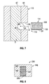
Fig. 7 is schematic representation of an example of another application of the disclosed frictional coupling; -
Fig. 8 is a schematic representation of a variation of the example ofFig. 6 ; -
Fig. 9 is a schematic representation of another example of an application of the disclosed frictional coupling, showing a second part engaging a first part; -
Fig. 10 is a schematic representation of an example of the disclosed frictional coupling associated with two planar surfaces; -
Fig. 11 is a schematic representation of a surface pattern of a frictional coupling according to one aspect of the disclosure; -
Fig. 12 is a schematic representation of a surface pattern of a frictional coupling according to another aspect of the disclosure; -
Fig. 13 is a schematic representation a surface pattern of a frictional coupling according to yet another aspect of the disclosure; and -
Fig. 14 is a schematic representation of a surface pattern of a frictional coupling according to still another aspect of the disclosure. - As shown in
Fig. 1 , a frictional coupling, generally designated 10, may be between afirst part 12 and asecond part 14. Thefirst part 12 may include a surface, e.g., afirst surface 22, having a shape (a first shape), and a surface roughness average (a first surface roughness average Ra1 ) that is less than or equal to about 500 microinches (13 microns). In one example, Ra1 may be less than or equal to about 250 microinches (6 microns), in another example less than or equal to about 125 microinches (3 microns), in a further example less than or equal to about 63 microinches (1.6 microns), in a further example less than or equal to about 32 microinches (0.8 microns), in a further example less than or equal to 16 microinches (0.4 microns), and in yet a further example less than or equal to about 8 microinches (0.2 microns). As used herein, a surface roughness average is the average deviation of a surface profile having a length L from a mean line. - The
second part 14 may include a surface, e.g., asecond surface 20. The shape of the first surface 22 (the first shape) and the shape of the second surface 20 (the second shape) are substantially complementary shapes. In one example, thefirst surface 20 and thesecond surface 22 may be substantially planar. In another example, thefirst surface 20 and thesecond surface 22 may be substantially non-planar, e.g., spherical, cylindrical, etc. - The
second part 14 may include projections, e.g.,projections 40 andprojections 41, arranged in apreselected pattern 24 that forms at least a portion of thesecond surface 20. Theprojections projections projections surface 20. As shown inFig. 1 , in an exemplary aspect of the disclosure, theprojections first surface 20 in a mutually convergent manner. Accordingly, theprojections first surface 22 and thesecond surface 20, as observed in the two-dimensional view ofFig. 1 . - As used herein, substantially complementary shapes are shapes whose geometric similarity is sufficient to ensure contact between the
first surface 22 and theprojections second surface 20. - Each of the
projections projections - In one example, the
projections second surface 20. In one aspect of the disclosure, theprojections projections second surface 20. In yet another example,projections second surface 20, i.e., the projections may be formed from a material different than that of the second surface and may be applied, as by sputtering or other well-known means, to the second surface. Theprojections projections 40, 41 (i.e., a preselected pattern thereof), such as a pattern of evenly spacedprojections - When the
first part 12 and thesecond part 14 are subjected to a biasing force F, which includes opposing forces mutually biasing thefirst part 12 and thesecond part 14, theprojections first surface 22. The ease of elastic deformation of the projections in response to the biasing force F varies based on the chosen geometric shape or shapes of theprojections first part 12 and thesecond part 14 responsive to the application of the biasing force F. In one example, the biasing force F and the resulting coupling may be based on either a locational interference fit or a force (shrink) fit. As used herein, a locational interference (press) fit may be a fit with small interferences designed for fixed couplings where precision and rigidity of fits of the coupled parts is the main requirement. Press fits cannot be used to transfer torsional moments using friction forces only; theparts parts 12, 14 (e.g., permanent couplings of gears with shafts, bearing bushings, flanges, etc.). These fits are designed, for example, to transfer torsional moments using friction forces. - In one example, the materials for the first and
second parts projections projections first surface 22. In one example, the force F, mutually biasing thefirst surface 22 and thesecond surface 20, may be sufficient to reach or exceed the AECR of theprojections first surface 22 and thesecond surface 20 against each other may be greater than zero, but may be insufficient to exceed the AECR for the projections, e.g., theprojections second surface 20 may have a second surface roughness average Ra2 which is sufficiently low to satisfy a fatigue-life requirement for thesecond part 14. In one aspect of the disclosure, thesecond surface 20 may have an Ra2 equal to or less than 125 microinches (3 microns). In the example ofFig. 1 , since thepattern 24 of theprojections Fig. 1 , the friction fit between thesurfaces first part 12 and thesecond part 14, is an isotropic friction fit capable of resisting movement of thefirst surface 22 relative to thesecond surface 20 in the plane ofFig. 1 . From the foregoing, those skilled in the art will appreciate that appropriately oriented additional projections may produce an isotropic friction fit between the first andsecond surfaces - As shown in
Fig. 1 , the elastic deformation of theprojections surface 22 of thesecond part 12. Theprojections surface 22. - As shown in
Fig. 2 , an example of the disclosed frictional coupling, generally designated 100, may include afirst part 12 and asecond part 14A that differs from thefirst part 14 ofFig. 1 in that thesecond part 14A may includeonly projections 40. Thus, apreselected pattern 24A ofprojections 40, forming at least a portion of the surface of thesecond part 14A, i.e., thesecond surface 20A, may be anisotropic. Accordingly, when the force F is applied to mutually bias thefirst part 12 and thesecond part 14A, an anisotropic friction fit between theparts first surface 12 and thesecond surface 14A may be configured to resist relative movement thereof in response to a force directed to produce such movement. - In one example, the average elastic compressive range of the
projections 40 may be substantially equal to the surface roughness average Ra1 of thefirst part 12. In one example, the biasing force F that may urge thefirst part 12 and thesecond part 14A together to produce a friction fit between the parts may be selected to be sufficient to deflect theprojections 40 to reach or exceed the average elastic compressive range of the projections. In one example, the force F selected to bias thefirst surface 12 and thesecond surface 14A is greater than zero, but is insufficient to exceed the average elastic compressive range. - The shape and orientation of the
projections 40 cause theanisotropic surface pattern 24A to oppose movement of thesecond part 14A relative to thefirst part 12 in a direction opposite to the direction of arrow A inFig. 2 when the biasing force F is applied. Conversely, the shape and orientation of theprojections 40 comprising theanisotropic surface pattern 24A allow slippage of thesecond part 14A relative to thefirst part 12 in the direction of arrow A inFig. 2 . - As shown in
Fig. 3 , another example of the disclosed frictional coupling, generally designated 200, may be between afirst part 12 and asecond part 14B having projections 40B. Theprojections 40B may be arranged in apreselected pattern 24B that may be an anisotropic pattern. Thefirst part 12 may include afirst surface 22 having a shape (a first shape) and a surface roughness (a first surface roughness average Ra1 ). Thesecond part 14B may include asecond surface 20B having a shape (a second shape) and a surface roughness average (a second surface roughness average Ra2 ). The first shape and the second shape are substantially complementary shapes. - The
pattern 24B may be a preselected pattern that forms at least a portion of thesecond surface 20B. In one example, theprojections 40B of preselectedpattern 24B may be configured to produce an anisotropic friction fit between thefirst surface 22 and thesecond surface 20B when the first surface and the second surface are biased against each other by a force F. - The
projections 40B of the preselectedsurface pattern 24B may include a first portion 28 that extends in a direction oblique to thesurface 22, and asecond portion 34 that extends obliquely from the first portion 28. The first portion 28 forms an undercut surface on each of theprojections 40B. This undercut is maintained as thefirst surface 22 andsecond surface 20B are biased against each other by force F. The first portion 28 may face in a direction opposite the direction of the arrow A inFig. 3 . - The first portions 28 and
second portions 34 collectively may form apattern 24B ofprojections 40B in cross section. In one example, the length of theindividual projection 40B may be 0.0030 inches (76 microns), measured in a general direction along thesurface 22. - As shown in
Fig. 3 , theanisotropic surface pattern 24B of thesecond part 14B may engage thesurface 22 of thefirst part 12 at the intersection of the first andsecond portions 28, 34 ofprojections 40B. The shape of theprojections 40B of theanisotropic surface pattern 24B may facilitate movement of thesecond part 14B relative to thefirst part 12 in the direction of arrow A, but resist relative movement in the opposite direction. - In one example, the
projections 40B may be shaped such that the height of the first portions 28, measured in a direction substantially normal to thefirst surface 22, may be approximately 0.0010 inches (25 microns), the length of thesecond portion 34 may be approximately 0.0040 inches (101 microns), measured in a direction along thefirst surface 22. The dimensions may have tolerances of plus or minus 0.0005 inches (13 microns). - Another example of the
frictional coupling 210 is shown inFig. 4 . In this example, thesecond part 14C may haveprojections 40C with a first undercutportion 28C, asecond portion 34C extending from the first portion, and athird portion 32C extending from the second portion. - As shown in
Fig. 5 , in another example of the frictional coupling, generally designated 220, thesecond part 14D may includeprojections 40D, each having afirst portion 28D, asecond portion 34D extending from the first portion, and athird portion 32D extending from the second portion. Thefirst portion 28D may include an undercut surface that is non-planar. This non-planar shape may reduce stress concentrations and fatigue failure of theprojections 40D. - In another example, shown in
Fig. 6 , the frictional coupling, generally designated 100 inFig. 2 , 200 inFig. 3 , 210 inFig. 4 and 220 inFig. 5 , may be used to secure asecond part 14, which inFig. 6 may be in the form of a tool (e.g., an end mill) to afirst part 12, which in one example may be a tool holder or receiver. The opposing surfaces of thecoupling 100 may be biased (urged) together with the use a friction fit in the form of, e.g., a shrink fit or a press fit. - The
receiver 12 may include acylindrical recess 16 that may be shaped to receive acylindrical shank 18 of thetool 14 with an interference fit, wherein the inside diameter of thecylindrical recess 16 may be slightly less than the outside diameter of theshank 18 before the coupling is effected. When, theshank 18 is, e.g., press fit into therecess 16 in the direction of arrow A, the external surface 20 (i.e., the second surface 20) of theshank 18 may engage the cylindrical wall 22 (i.e., the first surface 22) of thecylindrical recess 16. In one example, thetool 14 and thereceiver 12 may be made of steel or other metals or metallic alloys. In other examples, thecoupling 100 may be between first andsecond parts tool 14 may be made of tungsten carbide or a high-carbon tool steel, and thereceiver 12 may be made of steel, such as a mild steel. - The press fit between the
shank 18 and thecylindrical recess 16 of thereceiver 12 provides a friction force that causes the receiver to grip the shank securely under static loading. Higher normal forces of the tool holder upon the shank, such as the ones provided by a shrink fit, may increase the elastic deformation of the projections and improve the grip of thereceiver 12 upon thetool shank 18. The more projections (contact points) between theexternal surface 20 of theshank 18 and theinner wall 22 of thecylindrical recess 16 that remain engaged at the same time due to local elastic deformation of the projections, the less susceptible thecoupling 10 may be to unintended disassembly. In one example, theend 36 of theshank 18 may be chamfered at 38 to facilitate insertion of theshank 18 into therecess 16 of thereceiver 12. - The preselected surface pattern, e.g.,
anisotropic pattern 24B on the surface of theshank 18, may take the form of a plurality ofannular projections 40 shown inFig. 2 , 40B shown inFig. 3 , 40C inFig. 4 , or 40D inFig. 5 , or combinations thereof. In one or more aspects of the disclosure, theprojections 40 may be one of continuously formed or segmented, or combinations thereof. This anisotropic shape of theprojections 40, for example, may facilitate the movement of theshank 18 further into therecess 16 in the direction of arrow A, and resists movement of theshank 18 in the opposite direction, namely, outwardly from the recess in a direction opposite arrow A. By introducing a localized, weakened surface structure via an anisotropic surface pattern, e.g., thepreselected pattern 24B, more contact points may be realized through elastic deformation of, e.g., theprojections 40B thesurface pattern 24B. This surface configuration may operate to prevent the "walk out" phenomenon, in which vibration sustained by theshank 18 and/or theholder 12 may cause the shank to move in a direction opposite arrow A out of therecess 16. If the axial component of the external force, which may be associated with vibrations or shock loads, happens to be bi-directional (i.e., both pushing and pulling the shank 18), thecoupling 10 is thus tailored to favor assembly (i.e., insertion of theshank 18 into the recess 16) rather than disassembly. - While the projections, e.g.,
projections 40 ofFIG. 2 , are shown formed in an annular shape and arranged parallel to each other along the length of theshank 18 of thetool 14 in the example ofFig. 6 , the projections may be formed on theshank 18 in other orientations, e.g., an orientation that may be oblique relative to the longitudinal symmetry axis of theshank 18. Moreover, the projections may be formed as a continuous helical feature, or in discontinous segments of parallel annular projections or helical projections, as described with reference toFig. 12 , infra. In other examples, the preselected pattern of projections may not be parallel or helical, but may intersect itself, forming, e.g., a crosshatch pattern. - In one example shown in
Fig. 8 , the frictional coupling, generally designated 230, may include afirst part 14E in the form of a tool receiver having arecess 16E with a surface 22E that may include asurface pattern 24E in the form ofprojections 20E similar in shape to one or more of thesurface patterns 24A ofFig. 2 , 24B ofFig. 3 , 24C ofFig. 4 or 24D ofFig. 5 , shaped to provide an anisotropic friction fit. Thesurface pattern 24E is oriented in a direction opposite that of thesurface pattern 24B inFig. 3 , since thesurface pattern 24E is formed on awall 20E of thereceiver 14E for retaining a tool similar totool 14 ofFig. 6 , but with a substantially smooth surface without a preselected pattern thereon. - As shown in
Fig. 7 , in one example, thefrictional coupling 110 may include a first part in the form of areceiver 112 having arecess 116, and a second part in the form of a shank, for example apin 114 that is shaped to engage therecess 116. Thefirst part 112 may include at least twocomponents pin 114. In one example,component 42 may include aninner portion 46 of therecess 116 and thecomponent 44 may include anouter portion 48 of the recess. Theportions recess 116 that is shaped to receive thepin 114. In one or more aspects of the disclosure, there may exist a plurality of adjacently stacked portions or components of thefirst part 112, through which therecess 116 is formed to receive thepin 114 for joining the components. - The
pin 114 may include ananisotropic surface pattern 124 on all or a portion of itsouter surface 120. The projections of theanisotropic surface pattern 124 may be shaped as shown in one or more ofFigs. 2 ,3, 4 and 5 . These projections may be configured and oriented to promote the retention of thepin 114 within therecess 116, such that external vibration may cause thepin 114 to travel in the direction of the arrow A, which in the example ofFig. 7 may urge the pin further into therecess 116 and to resist slippage of thepin 114 in the opposite direction, namely, out of the recess. In one example, theanisotropic surface 124 may be formed on aninner surface 122 of therecess 116, as in the example ofFig. 8 , and the surface of thepin 112 may be smooth. In such an example, the orientation ofprojections 40 may be reversed from that shown inFigs. 2 ,3, 4, and 5 . Alternatively, the preselectedsurface pattern 124 may be an isotropic pattern, such as that described with reference toFIG. 1 , especially where therecess 116 is a through, rather than a blind, recess (not shown). - A method of forming a frictional coupling, such as
couplings first part 12, which may, for example, be a receiver, and providing thesecond part 14, which may, for example be a shank or a pin. The first part may have a surface, which may be thesurface 22 of therecess 16 ofFIG. 6 or thesurface 122 of therecess 116 ofFIG. 7 , shaped to engage thesurfaces shank 18 and thepin 114, respectively, with, e.g., an anisotropic interference fit.Patterns outer surfaces shank 18 andpin 114, respectively, using one or more of the methods mentioned previously. The first part, which may be theshank 18 or thepin 114, then may be inserted into therecesses tool holder 12 or thesecond part 112, respectively, with an anisotropic interference fit, such that thesurface pattern surface second part - In response to vibration experienced by the
first part second part surfaces anisotropic surfaces second parts recesses second part first part Fig. 9 ) or in a circumferential direction in the direction of arrow C. The coupling, e.g., thecoupling - The disclosed frictional couplings may be applicable to any mechanical interface where friction serves as a major contribution to interface integrity. In particular, such couplings may be used on cutters being held by any tool holder that relies upon hoop-stress retention of the cutter, such as shrink-fit tool holders, milling chucks, and hydraulic tool holders, without the need to provide additional components to effect the mechanical retention coupling. This design may enable higher performance capability from existing equipment without investment in new tool holders.
- Another example of the frictional coupling, generally designated 600, is shown in
Fig. 10 . In this example, thefirst part 612 may be in the form of a flat sheet or plate having afirst surface 616, and thesecond part 614 may be in the form of a correspondingly shaped flat sheet or plate. Thefirst part 612 may have afirst surface 616, facing thesecond part 614, and thesecond part 614 may have asecond surface 620, facing the first part. Thesecond surface 620 of thesecond part 614 may have projections, and preferably aplurality 640 ofdiscrete projections 50. Theprojections 50 are formed in apreselected pattern 624 on thesecond surface 620 and have a predefined shape, which imparts the projections with geometrically derived elasticity, as discussed above with respect to other aspects of the disclosure. Accordingly, the projections elastically deform responsive to a force F that mutually biases thefirst part 612 and thesecond part 614. For example, theprojections 50 may include undercut surfaces and/or may have a cross-section that tapers in the direction of thefirst surface 116. As a result, theprojections 50 may elastically deform in response to the biasing force F. - In one or more aspects of the disclosure, the first and
second surfaces second surfaces Fig. 9 . Referring back toFig. 10 , assuming that thefirst part 612 is held stationary and thesecond part 614 is urged in the direction of arrow E, theprojections 50 may be anisotropically oriented to oppose relative motion between the first andsecond surfaces first surface 616 andsecond surface 620 are mutually biased. Accordingly, the elastic deformation of theprojections 50 may be in the direction of the force F as well as along aline 52 parallel to arrow E. In one or more aspects of the disclosure, theline 52 may be rectilinear (see alsoFig. 9 ), and in other examples may be acurvilinear line 54. The anisotropic frictional properties of theprojections 50 may be predetermined by the manner in which they are shaped, oriented, and/or arranged in thepattern 624. In other examples, the frictional properties of the projections may be isotropic. - In the example of the frictional coupling, generally designated 300 and shown in
Fig. 11 , theprojections 50 may be formed on thefirst surface 320 of a cylindrically shapedsecond part 314, which is shaped to engage therecess 616A of thefirst part 12 shown inFig. 9 . In one example, thesecond part 314 may be a shank of a tool or other object. Theprojections 50 may be arranged in apattern 324 that varies in the density of projections along an axis D of the second part 314 (e.g., decreasing in density of protrusions from left to right inFig. 11 ). Further, thepattern 324 ofprojections 50 may be symmetric about the axis D. In other examples, thepattern 324 ofprojections 50 may be asymmetric, such aspattern 624 ofprojections 50 with respect toline 52 inFig. 10 . - In the example of the coupling, generally designated 400, shown in
Fig. 12 , the projections may take the form ofsegmented projections 426. Thesegmented projections 426 may have a profile similar to that of projections shown in one or more ofFigs. 2 ,3, 4 and 5 . Thesegmented projections 426 may be arranged in a plurality of patterns, such aspatterns 424, 424A. - In the example of the coupling, generally designated 500, shown in
Fig. 13 , thesecond part 514 may havepluralities 540 ofdiscrete projections Fig. 10 . These projections may be arranged in preselectedpatterns projections 50 inpattern 524 may be oriented to resist a combination of torsional and axial forces acting to separate the coupling. In other examples, additional preselected patterns ofprojections preselected pattern 524 may be interspersed with the projections ofpreselected pattern 524A. - As shown in
Fig. 14 , in an example of the frictional coupling, generally designated 700, thesurface 720 of thesecond part 714 may include a plurality of tapered projections 740 in the form of, e.g.,discrete cones 750. Projections 740 also may take the form of pyramids, tapered cylinders, or the like, and extend substantially perpendicularly from thesecond surface 720. Projections 740 are not oriented obliquely to thesurface 720. However, the projections 740 may be deflected to an orientation similar to that ofprojections 40 ofFig. 2 when the opposing surface of the frictional coupling are mutually biased by a force F. - Illustrative, non-exclusive examples of inventive subject matter according to the present disclosure are described in the clauses A1-F52, below:
- A1. A coupling between a first surface and a second surface, wherein:
- the first surface includes a first shape and a surface roughness average that is less than or equal to about 500 microinches (13 microns); and
- the second surface includes:
- a second shape, the first shape and the second shape being substantially complementary shapes, and
- projections, in a preselected pattern, forming at least a portion of the second surface, the projections configured to produce a friction fit between the first surface and the second surface when the first surface and the second surface are biased against each other, wherein an average elastic compressive range, substantially equal to the surface roughness average, is associated with the projections.
- A2. The coupling of clause A1, wherein a force biasing the first surface and the second surface against each other is sufficient to reach or exceed the average elastic compressive range.
- A3. The coupling of clause A1, wherein a force biasing the first surface and the second surface against each other is greater than zero, but is insufficient to exceed the average elastic compressive range.
- A4. The coupling of clause A1, wherein the friction fit is an anisotropic friction fit.
- A5. The coupling of clause A4, wherein the anisotropic friction fit between the first surface and the second surface is configured to resist relative movement of the first surface and the second surface in response to a force applied to at least one of the first surface and the second surface in at least one direction along the first surface.
- A6. The coupling of clause A1, wherein the friction fit is an isotropic friction fit.
- A7. The coupling of clause A6, wherein the isotropic friction fit between the first surface and the second surface is configured to resist relative movement of the first surface and the second surface in response to a force applied to at least one of the first surface and the second surface in any direction along the first surface.
- A8. The coupling of clause A1, wherein the preselected pattern is substantially symmetric.
- A9. The coupling of clause A1, wherein each of the projections has a predefined shape.
- A10. The coupling of clause A9, wherein the predefined shape provides the projections with a geometrically derived elasticity.
- A11. The coupling of clause A1, wherein the preselected pattern includes at least one axis of symmetry.
- A12. The coupling of clause A1, wherein the preselected pattern is asymmetric.
- A13. The coupling of clause A1, wherein the surface roughness average is less than or equal to about 250 microinches (6 microns).
- A14. The coupling of clause A1, wherein the surface roughness average is less than or equal to about 125 microinches (3 microns).
- A15. The coupling of clause A1, wherein the surface roughness average is less than or equal to about 63 microinches (1.6 microns).
- A16. The coupling of clause A1, wherein the surface roughness average is less than or equal to about 32 microinches (0.8 microns).
- A17. The coupling of clause A1, wherein the surface roughness average is less than or equal to about 16 microinches (0.4 microns).
- A18. The coupling of clause A1, wherein the surface roughness average is less than or equal to about 8 microinches (0.2 microns).
- A19. The coupling of clause A1, wherein the first surface is on one of a shank and a receiver and the second surface is on the other one of the shank and the receiver.
- A20. The coupling of clause A19, wherein the preselected pattern is configured to facilitate engaging the shank with the receiver and to oppose disengaging the shank and the receiver.
- A21. The coupling of clause A1, wherein the projections are one of continuously formed and segmented.
- A22. The coupling of clause A21, wherein each of the projections includes a cross section having a first portion and a second portion extending from the first portion.
- A23. The coupling of clause A22, further including a third portion extending from the second portion.
- A24. The coupling of clause A22, wherein the first portion of the cross section of at least one of the projections includes an undercut surface when the first surface and the second surface are biased against each other.
- A25. The coupling of clause A24, wherein the undercut surface is non-planar.
- A26. The coupling of clause A1, wherein each of the projections has a height of less than or equal to about 0.0010 inches.
- A27. The coupling of clause A1, wherein the projections include a first plurality of projections and a second plurality of projections, the first plurality of projections being different from the second plurality of projections.
- A28. The coupling of clause A27, wherein the first plurality of projections is arranged in a first pattern, and the second plurality of projections is arranged in a second pattern, the second pattern being different from the first pattern.
- A29. The coupling of clause A28, wherein at least one of the first pattern and the second pattern is an ordered pattern.
- A30. The coupling of clause A28, wherein the second pattern is interspersed with the first pattern.
- A31. The coupling of clause A28, wherein at least one of the first pattern and the second pattern varies in density along one of the second surface.
- A32. The coupling of clause A1, wherein the first surface and the second surface are substantially planar.
- A33. The coupling of clause A1, wherein the first surface and the second surface are substantially non-planar.
- A34. The coupling of clause A1, wherein the projections are consubstantially derived from the at least a portion of the second surface.
- A35. The coupling of clause A1, wherein the projections are not consubstantially derived from the at least a portion of the second surface.
- A36. The coupling of clause A1, wherein the projections are evenly distributed along the second surface.
- B37. A coupling between a first part and a second part, the coupling comprising:
- a first surface of the first part, wherein the first surface has a first shape and a surface roughness average that is less than or equal to about 500 microinches (13 microns);
- a second surface of the second part, wherein the second surface has a second shape, the first shape and the second shape being substantially complementary shapes; and
- projections that form at least a portion of the second surface in a preselected pattern, the projections configured to produce a friction fit between the first surface and the second surface when the first surface and the second surface are biased against each other, the projections having an average elastic compressive range substantially equal to the surface roughness average.
- B38. The coupling of clause B37, wherein a force biasing the first and the second surface against each other is sufficient to reach or exceed the average elastic compressive range.
- B39. The coupling of clause B37, wherein a force biasing the first and the second surface against each other is greater than zero, but is insufficient to exceed the average elastic compressive range.
- B40. The coupling of clause B37, wherein the second surface has a second surface roughness average sufficiently low to satisfy a fatigue-life requirement for the second part.
- B41. The coupling of clause B40, wherein the second surface has a surface roughness average equal to or less than 125 microinches (3 microns).
- C42. A method of forming a coupling between a first part and a second part, the method comprising:
- providing a first surface of the first part, wherein the first surface has a first shape and a surface roughness average that is less than or equal to about 500 microinches (13 microns);
- forming a second surface of the second part, the second surface having a second shape, the first shape and the second shape being substantially complementary shapes, wherein projections, forming at least a portion of the second surface in a preselected pattern, are configured to produce a friction fit between the first surface and the second surface when the first surface and the second surface are biased against each other, the projections having an average elastic compressive range substantially equal to the surface roughness average; and
- biasing the first surface and the second surface against each other with a force.
- C43. The method of clause C42, wherein the force is sufficient to reach or exceed the average elastic compressive range.
- C44. The method of clause C42, wherein the force is greater than zero, but is insufficient to exceed the average elastic compressive range.
- C45. The method of clause C42, wherein biasing the first surface and the second surface against each other includes forming one of a press fit and a shrink fit between the first part and the second part.
- D46. A method of at least partially forming a second part for a coupling between a first part and the second part, the first part including a first surface having a first shape and a surface roughness average that is less than or equal to about 500 microinches (13 microns), the method comprising:
- forming a second surface of the second part, the second surface having a second shape, the first shape and the second shape being substantially complementary shapes, wherein projections, forming at least a portion of the second surface in a preselected pattern, are configured to produce a friction fit between the first surface and the second surface when the first surface and the second surface are biased against each other, the projections having an average elastic compressive range substantially equal to the surface roughness average.
- E47. A method of forming a second surface for coupling with a first surface having a first shape and a surface roughness average that is less than or equal to about 500 microinches (13 microns), the method comprising:
- forming a second surface having a second shape, the first shape and the second shape being substantially complementary shapes, wherein projections, forming at least a portion of the second surface in a preselected pattern, are configured to produce a friction fit between the first surface and the second surface when the first surface and the second surface are biased against each other, wherein an average elastic compressive range, substantially equal to the surface roughness average, is associated with the projections.
- F48. A method of forming a coupling between a first surface and a second surface, the method comprising:
- providing the first surface that includes a first shape and a surface roughness average that is less than or equal to about 500 microinches (13 microns);
- forming the second surface that includes:
- a second shape, the first shape and the second shape being substantially complementary shapes, and
- projections, forming at least a portion of the second surface in a preselected pattern, configured to produce a friction fit between the first surface and the second surface when the first surface and the second surface are biased against each other, wherein an average elastic compressive range, substantially equal to the surface roughness average, is associated with the projections; and
- biasing the first surface and the second surface against each other with a force.
- F49. The method of clause F48, wherein the force is sufficient to reach or exceed the average elastic compressive range.
- F50. The method of clause F48, wherein the force is greater than zero, but is insufficient to exceed the average elastic compressive range.
- F51. The method of clause F48, wherein the preselected pattern is an anisotropic pattern formed by one of lithographically applied photoresist, chemical machining, and laser etching.
- F52. The method of clause F48, wherein forming the second surface includes forming the second surface on one of a shank and a receiver.
- While the forms of apparatus and methods herein described constitute exemplary aspects of the disclosure, it is to be understood that the disclosure is not limited to such forms of apparatus and methods, and that changes may be made therein without departing from the scope of disclosure.
Claims (15)
- A coupling between a first surface (22) and a second surface (20), wherein:the first surface (22) includes a first shape and a surface roughness average that is less than or equal to about 500 microinches (13 microns); andthe second surface (20) includes:a second shape, the first shape and the second shape being substantially complementary shapes, andprojections (40, 41), in a preselected pattern, forming at least a portion of the second surface (20), the projections (40, 41) configured to produce a friction fit between the first surface (22) and the second surface (20) when the first surface (22) and the second surface (20) are biased against each other, wherein an average elastic compressive range, substantially equal to the surface roughness average, is associated with the projections (40, 41).
- The coupling of claim 1, wherein a force biasing the first surface (22) and the second surface (20) against each other is sufficient to reach or exceed the average elastic compressive range.
- The coupling of claim 1, wherein a force biasing the first surface (22) and the second surface (20) against each other is greater than zero, but is insufficient to exceed the average elastic compressive range.
- The coupling of any of claims 1-3, wherein the friction fit is an anisotropic friction fit.
- The coupling of claim 4, wherein the anisotropic friction fit between the first surface (22) and the second surface (20) is configured to resist relative movement of the first surface (22) and the second surface (20) in response to a force applied to at least one of the first surface (22) and the second surface (20) in at least one direction along the first surface.
- The coupling of any of claims 1-3, wherein the friction fit is an isotropic friction fit.
- The coupling of claim 6, wherein the isotropic friction fit between the first surface (22) and the second surface (20) is configured to resist relative movement of the first surface (22) and the second surface (20) in response to a force applied to at least one of the first surface (22) and the second surface (20) in any direction along the first surface (22).
- The coupling of any of claims 1-7, wherein the preselected pattern is substantially symmetric.
- The coupling of any of claims 1-8, wherein each of the projections (40, 41) has a predefined shape.
- The coupling of claim 9, wherein the predefined shape provides the projections (40, 41) with a geometrically derived elasticity.
- The coupling of any of claims 1-10, wherein the preselected pattern includes at least one axis of symmetry.
- A method of forming a coupling between a first part (12) and a second part (14), the method comprising:providing a first surface (22) of the first part (12), wherein the first surface (22) has a first shape and a surface roughness average that is less than or equal to about 500 microinches (13 microns);forming a second surface (20) of the second part (14), the second surface (20) having a second shape, the first shape and the second shape being substantially complementary shapes, wherein projections (40, 41), forming at least a portion of the second surface (20) in a preselected pattern, are configured to produce a friction fit between the first surface (22) and the second surface (20) when the first surface (22) and the second surface (20) are biased against each other, the projections (40, 41) having an average elastic compressive range substantially equal to the surface roughness average; andbiasing the first surface (22) and the second surface (20) against each other with a force.
- The method of claim 12, wherein the force is sufficient to reach or exceed the average elastic compressive range.
- The method of claim 12, wherein the force is greater than zero, but is insufficient to exceed the average elastic compressive range.
- The method of any of claims 12-14, wherein biasing the first surface (22) and the second surface (20) against each other includes forming one of a press fit and a shrink fit between the first part (12) and the second part (14).
Applications Claiming Priority (1)
| Application Number | Priority Date | Filing Date | Title |
|---|---|---|---|
| US13/782,773 US9360029B2 (en) | 2013-03-01 | 2013-03-01 | Frictional Coupling |
Publications (3)
| Publication Number | Publication Date |
|---|---|
| EP2772656A2 true EP2772656A2 (en) | 2014-09-03 |
| EP2772656A3 EP2772656A3 (en) | 2017-05-03 |
| EP2772656B1 EP2772656B1 (en) | 2019-01-02 |
Family
ID=50272293
Family Applications (1)
| Application Number | Title | Priority Date | Filing Date |
|---|---|---|---|
| EP14157467.3A Active EP2772656B1 (en) | 2013-03-01 | 2014-03-03 | Frictional coupling |
Country Status (2)
| Country | Link |
|---|---|
| US (2) | US9360029B2 (en) |
| EP (1) | EP2772656B1 (en) |
Cited By (1)
| Publication number | Priority date | Publication date | Assignee | Title |
|---|---|---|---|---|
| US20240010265A1 (en) * | 2022-07-11 | 2024-01-11 | Steering Solutions Ip Holding Corporation | Laser textured friction surface for interfacing components |
Families Citing this family (9)
| Publication number | Priority date | Publication date | Assignee | Title |
|---|---|---|---|---|
| DE102014223505A1 (en) * | 2014-11-18 | 2016-05-19 | Zf Friedrichshafen Ag | Shaft-hub connection of a double gear on a gear shaft |
| WO2016134062A1 (en) * | 2015-02-17 | 2016-08-25 | Lehigh University | Controlling friction characteristics of resilient members using near-surface microstructures |
| US10010945B2 (en) | 2015-06-02 | 2018-07-03 | The Boeing Company | Receivers and methods for forming such receivers |
| US10071438B2 (en) * | 2015-06-02 | 2018-09-11 | The Boeing Company | Methods of forming shanks |
| GB201602857D0 (en) * | 2016-02-18 | 2016-04-06 | Rolls Royce Plc | Connection of rotatable parts |
| US10293971B2 (en) * | 2016-10-11 | 2019-05-21 | Velcro BVBA | Reclosable paperboard carton |
| WO2020012533A1 (en) * | 2018-07-09 | 2020-01-16 | オリンパス株式会社 | Remanufacturing method of medical device |
| AT523498A1 (en) * | 2020-02-07 | 2021-08-15 | Miba Sinter Austria Gmbh | Method for manufacturing a camshaft adjuster |
| US11454141B1 (en) | 2021-11-09 | 2022-09-27 | Borgwarner Inc. | Torque limited variable camshaft timing assembly |
Family Cites Families (29)
| Publication number | Priority date | Publication date | Assignee | Title |
|---|---|---|---|---|
| DE559779C (en) * | 1930-06-18 | 1932-09-23 | Heinrich Christiansen | Shrink connection |
| FR1596147A (en) * | 1968-01-11 | 1970-06-15 | ||
| DE2939037A1 (en) * | 1979-09-27 | 1981-04-09 | Union, Sils, van de Loo & Co, 5758 Fröndenberg | Connector for motorcycle generator shaft - has slotted end pressed into blind hole in rotor and including threads to provide locking action |
| US5344457A (en) * | 1986-05-19 | 1994-09-06 | The University Of Toronto Innovations Foundation | Porous surfaced implant |
| US5158557A (en) * | 1988-04-04 | 1992-10-27 | Minnesota Mining And Manufacturing Company | Refastenable adhesive tape closure |
| JPH078914Y2 (en) * | 1988-12-09 | 1995-03-06 | 光洋精工株式会社 | Coupling structure of shaft and ring |
| TW206182B (en) * | 1991-04-30 | 1993-05-21 | Sumitomo Chemical Co | |
| DE4121951C1 (en) | 1991-07-03 | 1992-12-24 | Supervis Ets | |
| US6517583B1 (en) * | 2000-01-30 | 2003-02-11 | Diamicron, Inc. | Prosthetic hip joint having a polycrystalline diamond compact articulation surface and a counter bearing surface |
| JPH08121120A (en) * | 1994-08-31 | 1996-05-14 | Nippon Piston Ring Co Ltd | Mechanical element formed by fitting shaft in engaging member |
| US5657516A (en) * | 1995-10-12 | 1997-08-19 | Minnesota Mining And Manufacturing Company | Dual structured fastener elements |
| US6015417A (en) * | 1996-01-25 | 2000-01-18 | Reynolds, Jr.; Walker | Surgical fastener |
| US7458991B2 (en) * | 2002-02-08 | 2008-12-02 | Howmedica Osteonics Corp. | Porous metallic scaffold for tissue ingrowth |
| US6872439B2 (en) * | 2002-05-13 | 2005-03-29 | The Regents Of The University Of California | Adhesive microstructure and method of forming same |
| DE10223234B4 (en) * | 2002-05-24 | 2005-02-03 | MAX-PLANCK-Gesellschaft zur Förderung der Wissenschaften e.V. | Process for the preparation of microstructured surfaces with increased adhesion and adhesion-enhancing modified surfaces |
| US7811272B2 (en) * | 2003-12-29 | 2010-10-12 | Kimberly-Clark Worldwide, Inc. | Nanofabricated gecko-like fasteners with adhesive hairs for disposable absorbent articles |
| US7141283B2 (en) * | 2004-02-24 | 2006-11-28 | Velcro Industries B.V. | Fasteners |
| US7327037B2 (en) * | 2004-04-01 | 2008-02-05 | Lucent Technologies Inc. | High density nanostructured interconnection |
| US7799423B2 (en) * | 2004-11-19 | 2010-09-21 | The Regents Of The University Of California | Nanostructured friction enhancement using fabricated microstructure |
| ES2349396T3 (en) * | 2005-06-20 | 2010-12-30 | Thyssenkrupp Presta Teccenter Ag | CAMSHAFT COMPOSITE. |
| DE102005062522C5 (en) * | 2005-12-19 | 2019-04-04 | Gehring Technologies Gmbh | Method for non-positive connection of the end faces of two machine components for transmitting high torques or shear forces |
| US8794574B2 (en) * | 2007-03-30 | 2014-08-05 | The Board Of Trustees Of The University Of Alabama | Micro-array surface for passive drag modification |
| US7780810B2 (en) * | 2007-07-16 | 2010-08-24 | RD & L Unique Products, LLC | Adhesion device for applying and releasing biomimetic microstructure adhesive from a contact surface |
| US8105334B2 (en) * | 2007-09-12 | 2012-01-31 | Boston Scientific Scimed, Inc. | Laser-resistant basket |
| US8206631B1 (en) * | 2008-09-18 | 2012-06-26 | Carnegie Mellon University | Methods of making dry adhesives |
| US8635749B2 (en) * | 2009-07-27 | 2014-01-28 | Nano Terra Inc. | Microadhesive systems and methods of making and using the same |
| US8703032B2 (en) * | 2009-10-14 | 2014-04-22 | Simon Fraser University | Biomimetic dry adhesives and methods of production therefor |
| EP2536528A1 (en) * | 2010-02-16 | 2012-12-26 | Ball Burnishing Machine Tools Ltd | Method of forming a coupling |
| JP2015199927A (en) * | 2014-03-31 | 2015-11-12 | キヤノン株式会社 | Adhesive member |
-
2013
- 2013-03-01 US US13/782,773 patent/US9360029B2/en active Active
-
2014
- 2014-03-03 EP EP14157467.3A patent/EP2772656B1/en active Active
-
2016
- 2016-04-29 US US15/143,010 patent/US10208775B2/en active Active
Non-Patent Citations (1)
| Title |
|---|
| None |
Cited By (1)
| Publication number | Priority date | Publication date | Assignee | Title |
|---|---|---|---|---|
| US20240010265A1 (en) * | 2022-07-11 | 2024-01-11 | Steering Solutions Ip Holding Corporation | Laser textured friction surface for interfacing components |
Also Published As
| Publication number | Publication date |
|---|---|
| US10208775B2 (en) | 2019-02-19 |
| US20140245584A1 (en) | 2014-09-04 |
| EP2772656B1 (en) | 2019-01-02 |
| US9360029B2 (en) | 2016-06-07 |
| US20160245315A1 (en) | 2016-08-25 |
| EP2772656A3 (en) | 2017-05-03 |
Similar Documents
| Publication | Publication Date | Title |
|---|---|---|
| EP2772656B1 (en) | Frictional coupling | |
| US9889506B2 (en) | Vibration-proof structure of rotating body | |
| US20100008746A1 (en) | Tie for identification ring | |
| JP2011158055A (en) | Positioning pin | |
| WO2006004965A2 (en) | Device and method for detachably connecting an impeller to a shaft | |
| CN104565074A (en) | Inner ring with undercut to improve tang flexibility | |
| JP2019094963A (en) | Coupling and its fixing method | |
| JP5385709B2 (en) | Article positioning mechanism | |
| CN103857487B (en) | Head Exchangeable Cutting Tools | |
| US10702945B2 (en) | Shanks | |
| KR20030068483A (en) | Coupling for modular tool holder arm | |
| US9227280B2 (en) | Spherical bearing retention clip | |
| US20140298941A1 (en) | Kinematically Coupled Gear Assemblies and Methods of Manufacturing the Same | |
| US9146002B2 (en) | Support structure and related assemblies and methods | |
| JP2017180769A (en) | Flexible spline for wave gear device and wave gear device using flexible spline | |
| US10688566B2 (en) | Receivers and methods for forming such receivers | |
| JP7257786B2 (en) | spring device | |
| Engelmann et al. | Machine Elements | |
| JP6838095B2 (en) | Connector | |
| CN106460907A (en) | Retainer for inner and outer shafts | |
| JP2006329415A (en) | Washer, and bolt nut | |
| TWI627358B (en) | One-way clutch | |
| TWM501493U (en) | Expansion screw | |
| JPWO2001058745A1 (en) | Track link and pin fixing structure | |
| JP2017020576A (en) | Disc spring |
Legal Events
| Date | Code | Title | Description |
|---|---|---|---|
| PUAI | Public reference made under article 153(3) epc to a published international application that has entered the european phase |
Free format text: ORIGINAL CODE: 0009012 |
|
| 17P | Request for examination filed |
Effective date: 20140303 |
|
| AK | Designated contracting states |
Kind code of ref document: A2 Designated state(s): AL AT BE BG CH CY CZ DE DK EE ES FI FR GB GR HR HU IE IS IT LI LT LU LV MC MK MT NL NO PL PT RO RS SE SI SK SM TR |
|
| AX | Request for extension of the european patent |
Extension state: BA ME |
|
| PUAL | Search report despatched |
Free format text: ORIGINAL CODE: 0009013 |
|
| AK | Designated contracting states |
Kind code of ref document: A3 Designated state(s): AL AT BE BG CH CY CZ DE DK EE ES FI FR GB GR HR HU IE IS IT LI LT LU LV MC MK MT NL NO PL PT RO RS SE SI SK SM TR |
|
| AX | Request for extension of the european patent |
Extension state: BA ME |
|
| RIC1 | Information provided on ipc code assigned before grant |
Ipc: F16D 1/08 20060101AFI20170329BHEP |
|
| GRAP | Despatch of communication of intention to grant a patent |
Free format text: ORIGINAL CODE: EPIDOSNIGR1 |
|
| STAA | Information on the status of an ep patent application or granted ep patent |
Free format text: STATUS: GRANT OF PATENT IS INTENDED |
|
| INTG | Intention to grant announced |
Effective date: 20180618 |
|
| GRAS | Grant fee paid |
Free format text: ORIGINAL CODE: EPIDOSNIGR3 |
|
| GRAJ | Information related to disapproval of communication of intention to grant by the applicant or resumption of examination proceedings by the epo deleted |
Free format text: ORIGINAL CODE: EPIDOSDIGR1 |
|
| GRAL | Information related to payment of fee for publishing/printing deleted |
Free format text: ORIGINAL CODE: EPIDOSDIGR3 |
|
| STAA | Information on the status of an ep patent application or granted ep patent |
Free format text: STATUS: REQUEST FOR EXAMINATION WAS MADE |
|
| GRAR | Information related to intention to grant a patent recorded |
Free format text: ORIGINAL CODE: EPIDOSNIGR71 |
|
| STAA | Information on the status of an ep patent application or granted ep patent |
Free format text: STATUS: GRANT OF PATENT IS INTENDED |
|
| INTC | Intention to grant announced (deleted) | ||
| GRAA | (expected) grant |
Free format text: ORIGINAL CODE: 0009210 |
|
| STAA | Information on the status of an ep patent application or granted ep patent |
Free format text: STATUS: THE PATENT HAS BEEN GRANTED |
|
| AK | Designated contracting states |
Kind code of ref document: B1 Designated state(s): AL AT BE BG CH CY CZ DE DK EE ES FI FR GB GR HR HU IE IS IT LI LT LU LV MC MK MT NL NO PL PT RO RS SE SI SK SM TR |
|
| INTG | Intention to grant announced |
Effective date: 20181123 |
|
| REG | Reference to a national code |
Ref country code: GB Ref legal event code: FG4D |
|
| REG | Reference to a national code |
Ref country code: CH Ref legal event code: EP Ref country code: AT Ref legal event code: REF Ref document number: 1084759 Country of ref document: AT Kind code of ref document: T Effective date: 20190115 |
|
| REG | Reference to a national code |
Ref country code: IE Ref legal event code: FG4D |
|
| REG | Reference to a national code |
Ref country code: DE Ref legal event code: R096 Ref document number: 602014038953 Country of ref document: DE |
|
| REG | Reference to a national code |
Ref country code: NL Ref legal event code: MP Effective date: 20190102 |
|
| REG | Reference to a national code |
Ref country code: LT Ref legal event code: MG4D |
|
| REG | Reference to a national code |
Ref country code: AT Ref legal event code: MK05 Ref document number: 1084759 Country of ref document: AT Kind code of ref document: T Effective date: 20190102 |
|
| PG25 | Lapsed in a contracting state [announced via postgrant information from national office to epo] |
Ref country code: NL Free format text: LAPSE BECAUSE OF FAILURE TO SUBMIT A TRANSLATION OF THE DESCRIPTION OR TO PAY THE FEE WITHIN THE PRESCRIBED TIME-LIMIT Effective date: 20190102 |
|
| PG25 | Lapsed in a contracting state [announced via postgrant information from national office to epo] |
Ref country code: PL Free format text: LAPSE BECAUSE OF FAILURE TO SUBMIT A TRANSLATION OF THE DESCRIPTION OR TO PAY THE FEE WITHIN THE PRESCRIBED TIME-LIMIT Effective date: 20190102 Ref country code: LT Free format text: LAPSE BECAUSE OF FAILURE TO SUBMIT A TRANSLATION OF THE DESCRIPTION OR TO PAY THE FEE WITHIN THE PRESCRIBED TIME-LIMIT Effective date: 20190102 Ref country code: SE Free format text: LAPSE BECAUSE OF FAILURE TO SUBMIT A TRANSLATION OF THE DESCRIPTION OR TO PAY THE FEE WITHIN THE PRESCRIBED TIME-LIMIT Effective date: 20190102 Ref country code: ES Free format text: LAPSE BECAUSE OF FAILURE TO SUBMIT A TRANSLATION OF THE DESCRIPTION OR TO PAY THE FEE WITHIN THE PRESCRIBED TIME-LIMIT Effective date: 20190102 Ref country code: PT Free format text: LAPSE BECAUSE OF FAILURE TO SUBMIT A TRANSLATION OF THE DESCRIPTION OR TO PAY THE FEE WITHIN THE PRESCRIBED TIME-LIMIT Effective date: 20190502 Ref country code: NO Free format text: LAPSE BECAUSE OF FAILURE TO SUBMIT A TRANSLATION OF THE DESCRIPTION OR TO PAY THE FEE WITHIN THE PRESCRIBED TIME-LIMIT Effective date: 20190402 Ref country code: FI Free format text: LAPSE BECAUSE OF FAILURE TO SUBMIT A TRANSLATION OF THE DESCRIPTION OR TO PAY THE FEE WITHIN THE PRESCRIBED TIME-LIMIT Effective date: 20190102 |
|
| PG25 | Lapsed in a contracting state [announced via postgrant information from national office to epo] |
Ref country code: BG Free format text: LAPSE BECAUSE OF FAILURE TO SUBMIT A TRANSLATION OF THE DESCRIPTION OR TO PAY THE FEE WITHIN THE PRESCRIBED TIME-LIMIT Effective date: 20190402 Ref country code: RS Free format text: LAPSE BECAUSE OF FAILURE TO SUBMIT A TRANSLATION OF THE DESCRIPTION OR TO PAY THE FEE WITHIN THE PRESCRIBED TIME-LIMIT Effective date: 20190102 Ref country code: LV Free format text: LAPSE BECAUSE OF FAILURE TO SUBMIT A TRANSLATION OF THE DESCRIPTION OR TO PAY THE FEE WITHIN THE PRESCRIBED TIME-LIMIT Effective date: 20190102 Ref country code: IS Free format text: LAPSE BECAUSE OF FAILURE TO SUBMIT A TRANSLATION OF THE DESCRIPTION OR TO PAY THE FEE WITHIN THE PRESCRIBED TIME-LIMIT Effective date: 20190502 Ref country code: HR Free format text: LAPSE BECAUSE OF FAILURE TO SUBMIT A TRANSLATION OF THE DESCRIPTION OR TO PAY THE FEE WITHIN THE PRESCRIBED TIME-LIMIT Effective date: 20190102 Ref country code: GR Free format text: LAPSE BECAUSE OF FAILURE TO SUBMIT A TRANSLATION OF THE DESCRIPTION OR TO PAY THE FEE WITHIN THE PRESCRIBED TIME-LIMIT Effective date: 20190403 |
|
| REG | Reference to a national code |
Ref country code: DE Ref legal event code: R097 Ref document number: 602014038953 Country of ref document: DE |
|
| PG25 | Lapsed in a contracting state [announced via postgrant information from national office to epo] |
Ref country code: AL Free format text: LAPSE BECAUSE OF FAILURE TO SUBMIT A TRANSLATION OF THE DESCRIPTION OR TO PAY THE FEE WITHIN THE PRESCRIBED TIME-LIMIT Effective date: 20190102 Ref country code: MC Free format text: LAPSE BECAUSE OF FAILURE TO SUBMIT A TRANSLATION OF THE DESCRIPTION OR TO PAY THE FEE WITHIN THE PRESCRIBED TIME-LIMIT Effective date: 20190102 Ref country code: AT Free format text: LAPSE BECAUSE OF FAILURE TO SUBMIT A TRANSLATION OF THE DESCRIPTION OR TO PAY THE FEE WITHIN THE PRESCRIBED TIME-LIMIT Effective date: 20190102 Ref country code: DK Free format text: LAPSE BECAUSE OF FAILURE TO SUBMIT A TRANSLATION OF THE DESCRIPTION OR TO PAY THE FEE WITHIN THE PRESCRIBED TIME-LIMIT Effective date: 20190102 Ref country code: IT Free format text: LAPSE BECAUSE OF FAILURE TO SUBMIT A TRANSLATION OF THE DESCRIPTION OR TO PAY THE FEE WITHIN THE PRESCRIBED TIME-LIMIT Effective date: 20190102 Ref country code: SK Free format text: LAPSE BECAUSE OF FAILURE TO SUBMIT A TRANSLATION OF THE DESCRIPTION OR TO PAY THE FEE WITHIN THE PRESCRIBED TIME-LIMIT Effective date: 20190102 Ref country code: EE Free format text: LAPSE BECAUSE OF FAILURE TO SUBMIT A TRANSLATION OF THE DESCRIPTION OR TO PAY THE FEE WITHIN THE PRESCRIBED TIME-LIMIT Effective date: 20190102 Ref country code: CZ Free format text: LAPSE BECAUSE OF FAILURE TO SUBMIT A TRANSLATION OF THE DESCRIPTION OR TO PAY THE FEE WITHIN THE PRESCRIBED TIME-LIMIT Effective date: 20190102 Ref country code: RO Free format text: LAPSE BECAUSE OF FAILURE TO SUBMIT A TRANSLATION OF THE DESCRIPTION OR TO PAY THE FEE WITHIN THE PRESCRIBED TIME-LIMIT Effective date: 20190102 |
|
| REG | Reference to a national code |
Ref country code: CH Ref legal event code: PL |
|
| PLBE | No opposition filed within time limit |
Free format text: ORIGINAL CODE: 0009261 |
|
| STAA | Information on the status of an ep patent application or granted ep patent |
Free format text: STATUS: NO OPPOSITION FILED WITHIN TIME LIMIT |
|
| PG25 | Lapsed in a contracting state [announced via postgrant information from national office to epo] |
Ref country code: SM Free format text: LAPSE BECAUSE OF FAILURE TO SUBMIT A TRANSLATION OF THE DESCRIPTION OR TO PAY THE FEE WITHIN THE PRESCRIBED TIME-LIMIT Effective date: 20190102 Ref country code: LU Free format text: LAPSE BECAUSE OF NON-PAYMENT OF DUE FEES Effective date: 20190303 |
|
| REG | Reference to a national code |
Ref country code: BE Ref legal event code: MM Effective date: 20190331 |
|
| 26N | No opposition filed |
Effective date: 20191003 |
|
| PG25 | Lapsed in a contracting state [announced via postgrant information from national office to epo] |
Ref country code: IE Free format text: LAPSE BECAUSE OF NON-PAYMENT OF DUE FEES Effective date: 20190303 Ref country code: LI Free format text: LAPSE BECAUSE OF NON-PAYMENT OF DUE FEES Effective date: 20190331 Ref country code: CH Free format text: LAPSE BECAUSE OF NON-PAYMENT OF DUE FEES Effective date: 20190331 |
|
| PG25 | Lapsed in a contracting state [announced via postgrant information from national office to epo] |
Ref country code: BE Free format text: LAPSE BECAUSE OF NON-PAYMENT OF DUE FEES Effective date: 20190331 Ref country code: SI Free format text: LAPSE BECAUSE OF FAILURE TO SUBMIT A TRANSLATION OF THE DESCRIPTION OR TO PAY THE FEE WITHIN THE PRESCRIBED TIME-LIMIT Effective date: 20190102 |
|
| PG25 | Lapsed in a contracting state [announced via postgrant information from national office to epo] |
Ref country code: TR Free format text: LAPSE BECAUSE OF FAILURE TO SUBMIT A TRANSLATION OF THE DESCRIPTION OR TO PAY THE FEE WITHIN THE PRESCRIBED TIME-LIMIT Effective date: 20190102 |
|
| PG25 | Lapsed in a contracting state [announced via postgrant information from national office to epo] |
Ref country code: MT Free format text: LAPSE BECAUSE OF NON-PAYMENT OF DUE FEES Effective date: 20190303 |
|
| PG25 | Lapsed in a contracting state [announced via postgrant information from national office to epo] |
Ref country code: CY Free format text: LAPSE BECAUSE OF FAILURE TO SUBMIT A TRANSLATION OF THE DESCRIPTION OR TO PAY THE FEE WITHIN THE PRESCRIBED TIME-LIMIT Effective date: 20190102 |
|
| PG25 | Lapsed in a contracting state [announced via postgrant information from national office to epo] |
Ref country code: HU Free format text: LAPSE BECAUSE OF FAILURE TO SUBMIT A TRANSLATION OF THE DESCRIPTION OR TO PAY THE FEE WITHIN THE PRESCRIBED TIME-LIMIT; INVALID AB INITIO Effective date: 20140303 |
|
| PG25 | Lapsed in a contracting state [announced via postgrant information from national office to epo] |
Ref country code: MK Free format text: LAPSE BECAUSE OF FAILURE TO SUBMIT A TRANSLATION OF THE DESCRIPTION OR TO PAY THE FEE WITHIN THE PRESCRIBED TIME-LIMIT Effective date: 20190102 |
|
| P01 | Opt-out of the competence of the unified patent court (upc) registered |
Effective date: 20230516 |
|
| PGFP | Annual fee paid to national office [announced via postgrant information from national office to epo] |
Ref country code: GB Payment date: 20260327 Year of fee payment: 13 |
|
| PGFP | Annual fee paid to national office [announced via postgrant information from national office to epo] |
Ref country code: DE Payment date: 20260327 Year of fee payment: 13 |
|
| PGFP | Annual fee paid to national office [announced via postgrant information from national office to epo] |
Ref country code: FR Payment date: 20260325 Year of fee payment: 13 |