EP2772530A1 - Cell culture assay - Google Patents
Cell culture assay Download PDFInfo
- Publication number
- EP2772530A1 EP2772530A1 EP12842801.8A EP12842801A EP2772530A1 EP 2772530 A1 EP2772530 A1 EP 2772530A1 EP 12842801 A EP12842801 A EP 12842801A EP 2772530 A1 EP2772530 A1 EP 2772530A1
- Authority
- EP
- European Patent Office
- Prior art keywords
- scaffold
- channel
- cell culture
- culture assay
- leak
- Prior art date
- Legal status (The legal status is an assumption and is not a legal conclusion. Google has not performed a legal analysis and makes no representation as to the accuracy of the status listed.)
- Granted
Links
Images



Classifications
-
- G—PHYSICS
- G01—MEASURING; TESTING
- G01N—INVESTIGATING OR ANALYSING MATERIALS BY DETERMINING THEIR CHEMICAL OR PHYSICAL PROPERTIES
- G01N33/00—Investigating or analysing materials by specific methods not covered by groups G01N1/00 - G01N31/00
- G01N33/48—Biological material, e.g. blood, urine; Haemocytometers
- G01N33/50—Chemical analysis of biological material, e.g. blood, urine; Testing involving biospecific ligand binding methods; Immunological testing
- G01N33/5005—Chemical analysis of biological material, e.g. blood, urine; Testing involving biospecific ligand binding methods; Immunological testing involving human or animal cells
-
- C—CHEMISTRY; METALLURGY
- C12—BIOCHEMISTRY; BEER; SPIRITS; WINE; VINEGAR; MICROBIOLOGY; ENZYMOLOGY; MUTATION OR GENETIC ENGINEERING
- C12M—APPARATUS FOR ENZYMOLOGY OR MICROBIOLOGY; APPARATUS FOR CULTURING MICROORGANISMS FOR PRODUCING BIOMASS, FOR GROWING CELLS OR FOR OBTAINING FERMENTATION OR METABOLIC PRODUCTS, i.e. BIOREACTORS OR FERMENTERS
- C12M23/00—Constructional details, e.g. recesses, hinges
- C12M23/02—Form or structure of the vessel
- C12M23/16—Microfluidic devices; Capillary tubes
-
- C—CHEMISTRY; METALLURGY
- C12—BIOCHEMISTRY; BEER; SPIRITS; WINE; VINEGAR; MICROBIOLOGY; ENZYMOLOGY; MUTATION OR GENETIC ENGINEERING
- C12M—APPARATUS FOR ENZYMOLOGY OR MICROBIOLOGY; APPARATUS FOR CULTURING MICROORGANISMS FOR PRODUCING BIOMASS, FOR GROWING CELLS OR FOR OBTAINING FERMENTATION OR METABOLIC PRODUCTS, i.e. BIOREACTORS OR FERMENTERS
- C12M1/00—Apparatus for enzymology or microbiology
- C12M1/34—Measuring or testing with condition measuring or sensing means, e.g. colony counters
-
- C—CHEMISTRY; METALLURGY
- C12—BIOCHEMISTRY; BEER; SPIRITS; WINE; VINEGAR; MICROBIOLOGY; ENZYMOLOGY; MUTATION OR GENETIC ENGINEERING
- C12M—APPARATUS FOR ENZYMOLOGY OR MICROBIOLOGY; APPARATUS FOR CULTURING MICROORGANISMS FOR PRODUCING BIOMASS, FOR GROWING CELLS OR FOR OBTAINING FERMENTATION OR METABOLIC PRODUCTS, i.e. BIOREACTORS OR FERMENTERS
- C12M23/00—Constructional details, e.g. recesses, hinges
- C12M23/34—Internal compartments or partitions
-
- C—CHEMISTRY; METALLURGY
- C12—BIOCHEMISTRY; BEER; SPIRITS; WINE; VINEGAR; MICROBIOLOGY; ENZYMOLOGY; MUTATION OR GENETIC ENGINEERING
- C12M—APPARATUS FOR ENZYMOLOGY OR MICROBIOLOGY; APPARATUS FOR CULTURING MICROORGANISMS FOR PRODUCING BIOMASS, FOR GROWING CELLS OR FOR OBTAINING FERMENTATION OR METABOLIC PRODUCTS, i.e. BIOREACTORS OR FERMENTERS
- C12M25/00—Means for supporting, enclosing or fixing the microorganisms, e.g. immunocoatings
- C12M25/14—Scaffolds; Matrices
-
- C—CHEMISTRY; METALLURGY
- C12—BIOCHEMISTRY; BEER; SPIRITS; WINE; VINEGAR; MICROBIOLOGY; ENZYMOLOGY; MUTATION OR GENETIC ENGINEERING
- C12M—APPARATUS FOR ENZYMOLOGY OR MICROBIOLOGY; APPARATUS FOR CULTURING MICROORGANISMS FOR PRODUCING BIOMASS, FOR GROWING CELLS OR FOR OBTAINING FERMENTATION OR METABOLIC PRODUCTS, i.e. BIOREACTORS OR FERMENTERS
- C12M3/00—Tissue, human, animal or plant cell, or virus culture apparatus
-
- C—CHEMISTRY; METALLURGY
- C12—BIOCHEMISTRY; BEER; SPIRITS; WINE; VINEGAR; MICROBIOLOGY; ENZYMOLOGY; MUTATION OR GENETIC ENGINEERING
- C12M—APPARATUS FOR ENZYMOLOGY OR MICROBIOLOGY; APPARATUS FOR CULTURING MICROORGANISMS FOR PRODUCING BIOMASS, FOR GROWING CELLS OR FOR OBTAINING FERMENTATION OR METABOLIC PRODUCTS, i.e. BIOREACTORS OR FERMENTERS
- C12M41/00—Means for regulation, monitoring, measurement or control, e.g. flow regulation
- C12M41/30—Means for regulation, monitoring, measurement or control, e.g. flow regulation of concentration
- C12M41/36—Means for regulation, monitoring, measurement or control, e.g. flow regulation of concentration of biomass, e.g. colony counters or by turbidity measurements
-
- C—CHEMISTRY; METALLURGY
- C12—BIOCHEMISTRY; BEER; SPIRITS; WINE; VINEGAR; MICROBIOLOGY; ENZYMOLOGY; MUTATION OR GENETIC ENGINEERING
- C12M—APPARATUS FOR ENZYMOLOGY OR MICROBIOLOGY; APPARATUS FOR CULTURING MICROORGANISMS FOR PRODUCING BIOMASS, FOR GROWING CELLS OR FOR OBTAINING FERMENTATION OR METABOLIC PRODUCTS, i.e. BIOREACTORS OR FERMENTERS
- C12M41/00—Means for regulation, monitoring, measurement or control, e.g. flow regulation
- C12M41/46—Means for regulation, monitoring, measurement or control, e.g. flow regulation of cellular or enzymatic activity or functionality, e.g. cell viability
-
- C—CHEMISTRY; METALLURGY
- C12—BIOCHEMISTRY; BEER; SPIRITS; WINE; VINEGAR; MICROBIOLOGY; ENZYMOLOGY; MUTATION OR GENETIC ENGINEERING
- C12Q—MEASURING OR TESTING PROCESSES INVOLVING ENZYMES, NUCLEIC ACIDS OR MICROORGANISMS; COMPOSITIONS OR TEST PAPERS THEREFOR; PROCESSES OF PREPARING SUCH COMPOSITIONS; CONDITION-RESPONSIVE CONTROL IN MICROBIOLOGICAL OR ENZYMOLOGICAL PROCESSES
- C12Q1/00—Measuring or testing processes involving enzymes, nucleic acids or microorganisms; Compositions therefor; Processes of preparing such compositions
- C12Q1/02—Measuring or testing processes involving enzymes, nucleic acids or microorganisms; Compositions therefor; Processes of preparing such compositions involving viable microorganisms
-
- G—PHYSICS
- G01—MEASURING; TESTING
- G01N—INVESTIGATING OR ANALYSING MATERIALS BY DETERMINING THEIR CHEMICAL OR PHYSICAL PROPERTIES
- G01N33/00—Investigating or analysing materials by specific methods not covered by groups G01N1/00 - G01N31/00
- G01N33/48—Biological material, e.g. blood, urine; Haemocytometers
-
- B—PERFORMING OPERATIONS; TRANSPORTING
- B01—PHYSICAL OR CHEMICAL PROCESSES OR APPARATUS IN GENERAL
- B01L—CHEMICAL OR PHYSICAL LABORATORY APPARATUS FOR GENERAL USE
- B01L2200/00—Solutions for specific problems relating to chemical or physical laboratory apparatus
- B01L2200/06—Fluid handling related problems
- B01L2200/0647—Handling flowable solids, e.g. microscopic beads, cells, particles
-
- B—PERFORMING OPERATIONS; TRANSPORTING
- B01—PHYSICAL OR CHEMICAL PROCESSES OR APPARATUS IN GENERAL
- B01L—CHEMICAL OR PHYSICAL LABORATORY APPARATUS FOR GENERAL USE
- B01L3/00—Containers or dishes for laboratory use, e.g. laboratory glassware; Droppers
- B01L3/50—Containers for the purpose of retaining a material to be analysed, e.g. test tubes
- B01L3/502—Containers for the purpose of retaining a material to be analysed, e.g. test tubes with fluid transport, e.g. in multi-compartment structures
- B01L3/5027—Containers for the purpose of retaining a material to be analysed, e.g. test tubes with fluid transport, e.g. in multi-compartment structures by integrated microfluidic structures, i.e. dimensions of channels and chambers are such that surface tension forces are important, e.g. lab-on-a-chip
- B01L3/502707—Containers for the purpose of retaining a material to be analysed, e.g. test tubes with fluid transport, e.g. in multi-compartment structures by integrated microfluidic structures, i.e. dimensions of channels and chambers are such that surface tension forces are important, e.g. lab-on-a-chip characterised by the manufacture of the container or its components
Definitions
- the present invention relates to a cell culture assay, and more particularly, to a cell culture assay having a structure which can easily and massively produce cells and more accurately observe a process of culturing cells.
- Cell migration means migration of living organisms or individual cells in response of various physical, chemical, and biological stimuli, and is deeply involved with various diseases and biological phenomena in a human body, such as AIDS, pathogenic and bacterial infections, arteriosclerosis, arthritis, periodontitis, psoriasis, cancer, multiple sclerosis, male infertility, asbestos poisoning, ozone poisoning, etc.
- the microfluidic technology can provide microenviromnents around a cell, allow real-time observation and accurate quantification of a reaction of cells, reduce an amount of cells or samples used in a test, and evaluate various test conditions.
- a scaffold-integrating technique can three-dimensionally introduce cells, culture cells in various directions, such as inside and both sides of a scaffold. Therefore, various cells can be cultured at the same time, and thereby interaction of the cells and interaction between the cells and the scaffolds can be studied. For this reason, the scaffold-integrating technique can also be applied in development of medical materials. Moreover, effects of various materials including a nanomaterial, a drug, and a protein on cells may be three-dimensionally evaluated.
- a microfluidic platform according to a conventional art needs a pole array having a size of several tens to several hundreds of micrometers to fix between scaffold channels. If there is no pole, scaffolds may be leaked into the channels, and therefore the conventional microfluidic platform cannot be applied.
- most scaffolds are present in a liquid type. They are solidified after being injected into a specific location in a channel, and therefore a pole is needed to block the injected scaffolds in the specific location before they are solidified.
- the above-described microfluidic platform has a limit to an area in which cells are reacted due to the pole preventing leakage of the scaffolds, and is very difficult to massively produce cells.
- the pole is still seen during observation, which becomes a factor disturbing quantification, and the critical problem is that the cells are preferentially reacted with the pole rather than the scaffolds.
- the present invention is directed to providing a cell culture assay having a structure not allowing cells to be preferentially reacted with scaffolds, and enabling to be fixed between scaffold channels at the same time.
- One aspect of the present invention provides a cell culture assay, which includes a substrate; a scaffold channel which is formed along the center inside the substrate, at least one of which is formed continuously, and inside which a scaffold flows; and a microfluidic channel which is formed on one side or on both sides of the scaffold channel, and inside which cells flow.
- a cell culture assay which includes a substrate; a scaffold channel which is formed along the center inside the substrate, at least one of which is formed continuously, and inside which a scaffold flows; and a microfluidic channel which is formed on one side or on both sides of the scaffold channel, and inside which cells flow.
- At least one of the ceiling surface and the floor surface of a boundary part of the microfluidic channel and the scaffold channel includes a leak-preventing part for preventing the scaffold from leaking into the microfluidic channel.
- the microfluidic channel and the scaffold channel have semicircular upper parts, and the semicircular upper parts are in contact with each other so that the leak-preventing part is formed at the boundary part therebetween.
- the leak-preventing part has a cross section which has a sharp tip and both sides of which are curved.
- the leak-preventing part is formed to have a rounded tip.
- the leak-preventing part is formed to have a tip having a square cross section.
- the leak-preventing part is formed to account for 5% to 95% of the height of the scaffold channel and the microfluidic channel.
- the scaffold channel and the microfluidic channel are alternately and repeatedly disposed.
- Both ends of the microfluidic channel extend in a direction being distant from the scaffold channel.
- a leak-preventing part extends to a ceiling surface or a floor surface of a boundary part of a scaffold channel and a microfluidic channel, cells are prevented from reacting first with other structures, thereby enabling accurate quantification in observation of cell culture and a reaction of cells and interaction of cells to be studied.
- a test time may be reduced by simultaneously observing various cells.
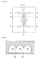
- FIG. 1 is a plan view of a cell culture assay according to one embodiment of the present invention
- FIG. 2 is a cross-sectional view taken along line I-I of FIG. 1 .
- a scaffold channel 20 and a microfluidic channel 30 are each formed on a rectangular substrate 10.
- the substrate 10 may be formed of a material that can realize a microfluidic structure in which a very small amount of any material can be transferred.
- microfluidic channels 30 in which cells flow are disposed at both sides of the substrate 10, and the scaffold channel 20 is disposed between the microfluidic channels 30.
- a plurality of scaffold channels 20 may be sequentially disposed between the microfluidic channels 30.
- the scaffold channels 20 are disposed in a straight line across the center of the substrate 10.
- a scaffold inlet 22 is formed in a front end (upstream) of the scaffold channel 20, and a scaffold outlet 24 is formed in a rear end (downstream) thereof.
- microfluid inlet and outlet 32 and 34 are respectively formed in front and rear ends of the microfluidic channel 30.
- scaffolds 50 in the scaffold channel 20, scaffolds 50 (refer to FIG. 3A ) flow, and due to the scaffolds 50 constituting an extracellular matrix (ECM), all of advantages of the microfluidic technology are maintained and a three-dimensional reaction of cells in evaluation of the cell flow may be simulated.
- Such scaffolds 50 must flow inside the scaffold channel 20 and must not leak into the microfluidic channel 30.
- the scaffolds 50 are a liquid type, and thus are solidified after being injected into a specific location in the scaffold channel 20.
- the scaffolds 50 may be formed of a material which becomes solidified or gelated, cured, sticky, or is formed into a pipe form, after being injected in a fluid type.
- a method of applying heat, chemically mixing, taking predetermined time, or irradiating light (particularly, UV rays) may be used.
- the solidified or gelated scaffolds 50 may be formed of alginate, collagen, a peptide, fibrin, hyaluronic acid, agarose, or PEG, and alternatively, a hydrogel, a general gel, an agarose gel, a tissue, a protein, or an actual matrix material may be used.
- the scaffolds 50 may be formed of a material directly extracted from a living body, for example, cells, a cell cluster, or living tissues, or a mixture thereof.
- both ends of the scaffold channel may have an inwardly depressed shape, and as time passes, the scaffolds 50 are scattered to both sides, as shown in FIG. 3B , they have a protruding shape.
- the shape may depend on a surface contact angle of the channel, and may be manipulated in a specific shape. According to the above-described process, the scaffolds 50 may be prevented from leaking into the microfluidic channel 30 due to surface tension with the leak-preventing part 40.
- the leak-preventing part 40 may be formed on a ceiling surface or floor surface of the boundary part of the scaffold channel 20 and the microfluidic channel 30, and in FIG. 2 , it is shown that the leak-preventing part 40 is formed on the ceiling surface.
- the leak-preventing part 40 has a cross section which has a sharp tip and both sides of which are curved. This shape may be realized by forming upper parts of the scaffold channel 20 and the microfluidic channel 30 in a semicircular shape, and disposing the semicircular parts in contact with each other.
- the leak-preventing part 40 may be formed to have a square cross section.
- the above-described leak-preventing part 40 extends to a predetermined length on the ceiling surface or the floor surface of the boundary part of the scaffold channel 20 and the microfluidic channel 30, but a shape of the leak-preventing part 40 is not particularly limited.
- the leak-preventing part 40 may be formed to account for 5% to 95% of the height of the scaffold channel 20 and the microfluidic channel 30.
- the leak-preventing part 40 may be formed to account for less than 5% of the height of the scaffold channel 20 and the microfluidic channel 30, capillarity may be difficult to be maintained, and when the leak-preventing part 40 is formed to account for more than 95%, a drug/molecule may not be actively migrated.
- the leak-preventing part 40 may be formed to account for various ranges, for example, 20% to 80%, 30% to 70%, or 40% to 60% of the height of the scaffold channel 20 and the microfluidic channel 30.
- both ends of the microfluidic channel 30 extend in a direction being distant from the scaffold channel 20 or in various methods. Accordingly, the scaffolds 50 substantially meet the fluid between the upstream and the downstream.
- cells may be cultured in various directions such as inside and both sides of the scaffold channel 20, and various cells can be cultured at the same time.
- interaction between cells and interaction between cells and scaffolds can be studied, which can be applied in development of medical materials.
- FIGS. 6A to 6C are perspective views showing a process of injecting scaffolds to the cell culture assay according to one embodiment of the present invention.
- the scaffolds 50 are injected into the scaffold inlet 22, and flow along the scaffold channel 20.
- the scaffold 50 may be fixed on the scaffold channel 20 without leaking into the microfluidic channel 30 due to the leak-preventing part 40 although injected in an amount indicated in FIG. 6C .
- FIGS. 7A and 7B are perspective views of cross sections of different channel structures of the cell culture assay according to the present invention.
- the scaffold channel 20 and the microfluidic channel 30 of the cell culture assay may be disposed in various manners.
- the microfluidic channels 30 are disposed at both sides, and one scaffold channel 20 is disposed therebetween.
- FIG. 8 shows culture of vascular endothelial cells through the conventional cell culture assay.
- vascular endothelial cells are grown along a pole array and a wall in the conventional art. That is, there is a limit to an area in which the cells are reacted, the pole is still shown during observation, which disrupts quantification, and the cells are preferentially reacted with the pole array.
- parts represented in red are preferably wider to observe interactions between cells, between cells and gels, and by chemical factors. However, to maintain surface tension, the parts in red have a limit to be enlarged.
- the cell culture assay described above is generally used in evaluation of cell migration under various environmental conditions, and can be applied in various uses such as development of new drugs, construction of disease models such as cancers, Alzheimer's, etc., construction of tissues and organ models, simulation of biological environment, toxicity evaluation, drug evaluation, contamination evaluation, protein and other material evaluation, biocompatibility evaluation, stem cell studies, etc.
Landscapes
- Health & Medical Sciences (AREA)
- Chemical & Material Sciences (AREA)
- Life Sciences & Earth Sciences (AREA)
- Engineering & Computer Science (AREA)
- Organic Chemistry (AREA)
- Wood Science & Technology (AREA)
- Zoology (AREA)
- Bioinformatics & Cheminformatics (AREA)
- Biomedical Technology (AREA)
- Biotechnology (AREA)
- Biochemistry (AREA)
- General Health & Medical Sciences (AREA)
- Microbiology (AREA)
- Genetics & Genomics (AREA)
- General Engineering & Computer Science (AREA)
- Sustainable Development (AREA)
- Analytical Chemistry (AREA)
- Immunology (AREA)
- Molecular Biology (AREA)
- Cell Biology (AREA)
- Clinical Laboratory Science (AREA)
- Hematology (AREA)
- Urology & Nephrology (AREA)
- Medicinal Chemistry (AREA)
- Physics & Mathematics (AREA)
- Food Science & Technology (AREA)
- General Physics & Mathematics (AREA)
- Pathology (AREA)
- Dispersion Chemistry (AREA)
- Proteomics, Peptides & Aminoacids (AREA)
- Tropical Medicine & Parasitology (AREA)
- Biophysics (AREA)
- Virology (AREA)
- Apparatus Associated With Microorganisms And Enzymes (AREA)
Abstract
Description
- The present invention relates to a cell culture assay, and more particularly, to a cell culture assay having a structure which can easily and massively produce cells and more accurately observe a process of culturing cells.
- Cell migration means migration of living organisms or individual cells in response of various physical, chemical, and biological stimuli, and is deeply involved with various diseases and biological phenomena in a human body, such as AIDS, pathogenic and bacterial infections, arteriosclerosis, arthritis, periodontitis, psoriasis, cancer, multiple sclerosis, male infertility, asbestos poisoning, ozone poisoning, etc.
- However, most conventional cell migration evaluating assays are used for two-dimensional cell migration, and thus could not help observing crawling of cells. Here, since cells actually exist in a three-dimensional space, the conventional assays frequently obtained results different from the real phenomenon.
- While assays analyzing three-dimensional cell migration, tissue formation, morphological changes, cell proliferation, etc. have been developed abroad, they had limits to expose cells under specific conditions or simulate real three-dimensional migration occurring in living organisms, and thus did not effectively evaluate and digitize test results.
- Here, when scaffolds constituting an extracellular matrix (ECM) are introduced into a microfluidic channel, all advantages of microfluidic technology may be maintained, and reactions of cells in evaluation environments such as cell migration and morphological changes, tissue formation, cell proliferation, etc. can be three-dimensionally simulated.
- As a conventional art reflecting such advantages, International Patent No.
WO2009/126524 is provided. According to the conventional art, three-dimensional simulation of angiogenesis is succeeded by introducing a collagen scaffold which is one of the ECMs, and results of studies on reactions between vascular endothelial cells and cancer cells, between liver cells and vascular endothelial cells, and between nerve cells. - Here, the microfluidic technology can provide microenviromnents around a cell, allow real-time observation and accurate quantification of a reaction of cells, reduce an amount of cells or samples used in a test, and evaluate various test conditions.
- In addition, a scaffold-integrating technique can three-dimensionally introduce cells, culture cells in various directions, such as inside and both sides of a scaffold. Therefore, various cells can be cultured at the same time, and thereby interaction of the cells and interaction between the cells and the scaffolds can be studied. For this reason, the scaffold-integrating technique can also be applied in development of medical materials. Moreover, effects of various materials including a nanomaterial, a drug, and a protein on cells may be three-dimensionally evaluated.
- However, a microfluidic platform according to a conventional art needs a pole array having a size of several tens to several hundreds of micrometers to fix between scaffold channels. If there is no pole, scaffolds may be leaked into the channels, and therefore the conventional microfluidic platform cannot be applied. With reference, most scaffolds are present in a liquid type. They are solidified after being injected into a specific location in a channel, and therefore a pole is needed to block the injected scaffolds in the specific location before they are solidified.
- However, the above-described microfluidic platform has a limit to an area in which cells are reacted due to the pole preventing leakage of the scaffolds, and is very difficult to massively produce cells. In addition, the pole is still seen during observation, which becomes a factor disturbing quantification, and the critical problem is that the cells are preferentially reacted with the pole rather than the scaffolds.
- Therefore, the present invention is directed to providing a cell culture assay having a structure not allowing cells to be preferentially reacted with scaffolds, and enabling to be fixed between scaffold channels at the same time.
- However, the technical object of the present invention to be achieved is not limited to the above-described object, and other objects not described herein will be clearly understood by those of ordinary skill in the art with reference to the following descriptions.
- One aspect of the present invention provides a cell culture assay, which includes a substrate; a scaffold channel which is formed along the center inside the substrate, at least one of which is formed continuously, and inside which a scaffold flows; and a microfluidic channel which is formed on one side or on both sides of the scaffold channel, and inside which cells flow. At least one of the ceiling surface and the floor surface of a boundary part of the microfluidic channel and the scaffold channel includes a leak-preventing part for preventing the scaffold from leaking into the microfluidic channel.
- The microfluidic channel and the scaffold channel have semicircular upper parts, and the semicircular upper parts are in contact with each other so that the leak-preventing part is formed at the boundary part therebetween.
- The leak-preventing part has a cross section which has a sharp tip and both sides of which are curved.
- The leak-preventing part is formed to have a rounded tip.
- The leak-preventing part is formed to have a tip having a square cross section.
- The leak-preventing part is formed to account for 5% to 95% of the height of the scaffold channel and the microfluidic channel.
- The scaffold channel and the microfluidic channel are alternately and repeatedly disposed.
- Both ends of the microfluidic channel extend in a direction being distant from the scaffold channel.
- According to the present invention, as a leak-preventing part extends to a ceiling surface or a floor surface of a boundary part of a scaffold channel and a microfluidic channel, cells are prevented from reacting first with other structures, thereby enabling accurate quantification in observation of cell culture and a reaction of cells and interaction of cells to be studied.
- In addition, as a scaffold channel and a microfluidic channel are disposed in various manners, a test time may be reduced by simultaneously observing various cells.
-
-
FIG. 1 is a plan view of a cell culture assay according to one embodiment of the present invention. -
FIG. 2 is a cross-sectional diagram taken along line I-I ofFIG. 1 . -
FIGS. 3A and 3B are diagrams showing that a scaffold is injected into the cell culture assay according to one embodiment of the present invention and then solidified. -
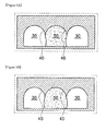
FIGS. 4 and 5 are cross-sectional views of different shapes of channels of the cell culture assay of the present invention. -
FIGS. 6A to 6C are perspective views showing a process of injecting a scaffold into the cell culture assay according to one embodiment of the present invention. -
FIGS. 7A and7B are perspective views showing cross sections of different channel structures of the cell culture assay of the present invention. -
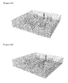
FIG. 8 is an image showing a cell culturing state in a conventional cell culture assay. -
FIG. 9 is an image showing a cell culturing state in the cell culture assay of the present invention. - Hereinafter, an embodiment of a cell culture assay of the present invention will be described in detail with reference to the accompanying drawings.
-
FIG. 1 is a plan view of a cell culture assay according to one embodiment of the present invention, andFIG. 2 is a cross-sectional view taken along line I-I ofFIG. 1 . - As shown in
FIG. 1 , ascaffold channel 20 and amicrofluidic channel 30 are each formed on a rectangular substrate 10. The substrate 10 may be formed of a material that can realize a microfluidic structure in which a very small amount of any material can be transferred. - The
microfluidic channels 30 in which cells flow are disposed at both sides of the substrate 10, and thescaffold channel 20 is disposed between themicrofluidic channels 30. Although will be described below, a plurality ofscaffold channels 20 may be sequentially disposed between themicrofluidic channels 30. - The
scaffold channels 20 are disposed in a straight line across the center of the substrate 10. Ascaffold inlet 22 is formed in a front end (upstream) of thescaffold channel 20, and ascaffold outlet 24 is formed in a rear end (downstream) thereof. In addition, microfluid inlet andoutlet microfluidic channel 30. - In the embodiment, in the
scaffold channel 20, scaffolds 50 (refer toFIG. 3A ) flow, and due to thescaffolds 50 constituting an extracellular matrix (ECM), all of advantages of the microfluidic technology are maintained and a three-dimensional reaction of cells in evaluation of the cell flow may be simulated.Such scaffolds 50 must flow inside thescaffold channel 20 and must not leak into themicrofluidic channel 30. In addition, thescaffolds 50 are a liquid type, and thus are solidified after being injected into a specific location in thescaffold channel 20. - In the embodiment, the
scaffolds 50 may be formed of a material which becomes solidified or gelated, cured, sticky, or is formed into a pipe form, after being injected in a fluid type. To solidify thescaffolds 50, a method of applying heat, chemically mixing, taking predetermined time, or irradiating light (particularly, UV rays) may be used. In addition, the solidified orgelated scaffolds 50 may be formed of alginate, collagen, a peptide, fibrin, hyaluronic acid, agarose, or PEG, and alternatively, a hydrogel, a general gel, an agarose gel, a tissue, a protein, or an actual matrix material may be used. In addition, thescaffolds 50 may be formed of a material directly extracted from a living body, for example, cells, a cell cluster, or living tissues, or a mixture thereof. - Here, as in the conventional art, when the
scaffolds 50 are blocked in a specific location by a pole array, cells are preferentially reacted with the pole array rather than thescaffolds 50, a problem of which may be solved, in the embodiment, by disposing a leak-preventingpart 40 at a boundary part in which thescaffold channel 20 meets themicrofluidic channel 30. That is, the conventional pole array is removed, and the leak-preventingpart 40 is formed to extend to a predetermined length on a ceiling surface or floor surface in the boundary part of thescaffold channel 20 and themicrofluidic channel 30. - As described above, the process of injecting the
scaffolds 50 while the leak-preventingpart 40 is formed is simply shown inFIGS. 3A and 3B . Referring toFIGS. 3A and 3B , when thescaffolds 50 first flow into thescaffold channel 20, as shown inFIG. 3A , due to cohesive strength of thescaffolds 50 by themselves, both ends of the scaffold channel may have an inwardly depressed shape, and as time passes, thescaffolds 50 are scattered to both sides, as shown inFIG. 3B , they have a protruding shape. The shape may depend on a surface contact angle of the channel, and may be manipulated in a specific shape. According to the above-described process, thescaffolds 50 may be prevented from leaking into themicrofluidic channel 30 due to surface tension with the leak-preventingpart 40. - Meanwhile, the leak-preventing
part 40, as described above, may be formed on a ceiling surface or floor surface of the boundary part of thescaffold channel 20 and themicrofluidic channel 30, and inFIG. 2 , it is shown that the leak-preventingpart 40 is formed on the ceiling surface. Most preferably, as shown inFIG. 2 , the leak-preventingpart 40 has a cross section which has a sharp tip and both sides of which are curved. This shape may be realized by forming upper parts of thescaffold channel 20 and themicrofluidic channel 30 in a semicircular shape, and disposing the semicircular parts in contact with each other. - However, in the process of forming the substrate 10 in practice, instead of the sharp tip formed as shown in
FIG. 2 , a rounded tip may be formed as shown inFIG. 4 . In addition, as shown inFIG. 5 , the leak-preventingpart 40 may be formed to have a square cross section. - As a result, the above-described leak-preventing
part 40 extends to a predetermined length on the ceiling surface or the floor surface of the boundary part of thescaffold channel 20 and themicrofluidic channel 30, but a shape of the leak-preventingpart 40 is not particularly limited. - In addition, the leak-preventing
part 40 may be formed to account for 5% to 95% of the height of thescaffold channel 20 and themicrofluidic channel 30. Here, when the leak-preventingpart 40 is formed to account for less than 5% of the height of thescaffold channel 20 and themicrofluidic channel 30, capillarity may be difficult to be maintained, and when the leak-preventingpart 40 is formed to account for more than 95%, a drug/molecule may not be actively migrated. For example, the leak-preventingpart 40 may be formed to account for various ranges, for example, 20% to 80%, 30% to 70%, or 40% to 60% of the height of thescaffold channel 20 and themicrofluidic channel 30. - Meanwhile, both ends of the
microfluidic channel 30 extend in a direction being distant from thescaffold channel 20 or in various methods. Accordingly, thescaffolds 50 substantially meet the fluid between the upstream and the downstream. In addition, cells may be cultured in various directions such as inside and both sides of thescaffold channel 20, and various cells can be cultured at the same time. In addition, using the above-described structure, interaction between cells and interaction between cells and scaffolds can be studied, which can be applied in development of medical materials. - Meanwhile,
FIGS. 6A to 6C are perspective views showing a process of injecting scaffolds to the cell culture assay according to one embodiment of the present invention. - As shown in
FIGS. 6A to 6C , thescaffolds 50 are injected into thescaffold inlet 22, and flow along thescaffold channel 20. In addition, thescaffold 50 may be fixed on thescaffold channel 20 without leaking into themicrofluidic channel 30 due to the leak-preventingpart 40 although injected in an amount indicated inFIG. 6C . - Then,
FIGS. 7A and7B are perspective views of cross sections of different channel structures of the cell culture assay according to the present invention. - As shown in
FIGS. 7A and7B , thescaffold channel 20 and themicrofluidic channel 30 of the cell culture assay may be disposed in various manners. In the above-described embodiment with reference toFIG. 2 , themicrofluidic channels 30 are disposed at both sides, and onescaffold channel 20 is disposed therebetween. - However, arrangement of the
scaffold channel 20 and themicrofluidic channel 30 is not necessarily limited to the above-described embodiment, as shown inFIG. 4 , a plurality ofscaffold channels 20 may be sequentially disposed, and as shown inFIG. 5 , thescaffold channel 20 and themicrofluidic channel 30 may be alternately and repeatedly disposed. As thescaffold channel 20 and themicrofluidic channel 30 are disposed in various ways as described above, various kinds of cell culture may be simultaneously confirmed. - Hereinafter, embodiments of cell culture according to the conventional art and the present invention will be compared by images with reference to
FIGS. 8 and9 . -
FIG. 8 shows culture of vascular endothelial cells through the conventional cell culture assay. Referring toFIG. 8 , it could be confirmed that, according to a part represented in yellow, vascular endothelial cells are grown along a pole array and a wall in the conventional art. That is, there is a limit to an area in which the cells are reacted, the pole is still shown during observation, which disrupts quantification, and the cells are preferentially reacted with the pole array. In addition, parts represented in red are preferably wider to observe interactions between cells, between cells and gels, and by chemical factors. However, to maintain surface tension, the parts in red have a limit to be enlarged. - On the other hand, referring to
FIG. 9 , it can be confirmed that the vascular endothelial cells are stably grown. Therefore, according to the cell culture assay of the present invention, the interactions between cells, between cells and gels and by chemical factors are easily observed, and the substrate is also easily formed. - In addition, referring to
FIGS. 8 and9 , the vascular endothelial cells are used as an example, but it is apparent that the cell culture assay according to the present invention uses various cells including the vascular endothelial cells. - Meanwhile, the cell culture assay described above is generally used in evaluation of cell migration under various environmental conditions, and can be applied in various uses such as development of new drugs, construction of disease models such as cancers, Alzheimer's, etc., construction of tissues and organ models, simulation of biological environment, toxicity evaluation, drug evaluation, contamination evaluation, protein and other material evaluation, biocompatibility evaluation, stem cell studies, etc.
- While the invention has been shown and described with reference to certain exemplary embodiments thereof, it will be understood by those skilled in the art that various modifications in form and details may be made therein without departing from the spirit and scope of the invention as defined by the appended claims.
Claims (10)
- A cell culture assay, comprising:a substrate;a scaffold channel which is formed along the centre inside the substrate, and of which at least one is disposed continuously, and inside which a scaffold flows; anda microfluidic channel which is formed on one side or on both sides of the scaffold channel, and inside which cells flow, wherein at least one of the ceiling surface and the floor surface of a boundary part of the microfluidic channel and the scaffold channel includes a leak-preventing part for preventing the scaffold from leaking into the microfluidic channel.
- The cell culture assay of claim 1, wherein the microfluidic channel and the scaffold channel have semicircular upper parts, and the semicircular upper parts are in contact with each other, so that the leak-preventing part is formed at the boundary part therebetween.
- The cell culture assay of claim 1, wherein the leak-preventing part has a sharp tip having a cross section, the both sides of which are in the shape of a curve.
- The cell culture assay of claim 1, wherein the leak-preventing part is formed to have a rounded tip.
- The cell culture assay of claim 1, wherein the leak-preventing part is formed to have a tip having a square cross section.
- The cell culture assay of claim 1, wherein the leak-preventing part is formed to account for 5% to 95% of the height of the scaffold channel and the microfluidic channel.
- The cell culture assay of claim 1, wherein the scaffold channel and the microfluidic channel are disposed in an alternate and repetitive manner.
- The cell culture assay of claim 1, wherein the microfluidic channel has both ends extending in a direction being distant from the scaffold channel.
- The cell culture assay of claim 1, wherein the scaffold is injected in a fluid form to gelate or is formed of curable materials.
- The cell culture assay of claim 1, wherein the scaffold is formed of one of alginate, collagen, peptide, fibrin, hyaluronic acid, agarose, polyhydroxyethylmethacrylate (PHEMA), polyvinyl alcohol (PVA), Poly(ethylene glycol)(PEG), Poly(ethylene oxide)(PEO), polyethylene (glycol) diacrylate(PEGDA), gelatin, matrigel, poly(L-lactic acid)(PLLA), carboxymethylcellulose, SAP, PHEMA-MMA, dextran, and chitosan or a mixture of two or more materials.
Applications Claiming Priority (2)
| Application Number | Priority Date | Filing Date | Title |
|---|---|---|---|
| KR1020110111302A KR101322798B1 (en) | 2011-10-28 | 2011-10-28 | Cell culture assay |
| PCT/KR2012/008917 WO2013062383A1 (en) | 2011-10-28 | 2012-10-29 | Cell culture assay |
Publications (3)
| Publication Number | Publication Date |
|---|---|
| EP2772530A1 true EP2772530A1 (en) | 2014-09-03 |
| EP2772530A4 EP2772530A4 (en) | 2015-07-15 |
| EP2772530B1 EP2772530B1 (en) | 2019-04-03 |
Family
ID=48168114
Family Applications (1)
| Application Number | Title | Priority Date | Filing Date |
|---|---|---|---|
| EP12842801.8A Active EP2772530B1 (en) | 2011-10-28 | 2012-10-29 | Cell culture assay |
Country Status (5)
| Country | Link |
|---|---|
| US (1) | US9523672B2 (en) |
| EP (1) | EP2772530B1 (en) |
| JP (2) | JP2014530635A (en) |
| KR (1) | KR101322798B1 (en) |
| WO (1) | WO2013062383A1 (en) |
Cited By (3)
| Publication number | Priority date | Publication date | Assignee | Title |
|---|---|---|---|---|
| CN105713835A (en) * | 2014-12-05 | 2016-06-29 | 中国科学院大连化学物理研究所 | Multi-functional-region cell three-dimensional co-culture method based on micro-fluidic chip |
| IT201600131735A1 (en) * | 2016-12-28 | 2018-06-28 | Milano Politecnico | THREE-DIMENSIONAL MULTI-LAYER BUILDINGS IN MICROCANALS |
| EP4589000A1 (en) * | 2024-01-18 | 2025-07-23 | Korea University Research and Business Foundation | Microfluidic chip and method for producing spheroid or organoid in vitro model using the same |
Families Citing this family (17)
| Publication number | Priority date | Publication date | Assignee | Title |
|---|---|---|---|---|
| KR101322798B1 (en) * | 2011-10-28 | 2013-10-29 | 고려대학교 산학협력단 | Cell culture assay |
| KR101896618B1 (en) * | 2015-12-07 | 2018-09-07 | 서울대학교산학협력단 | System for transfer and tracking of extracellular vesicles |
| KR20170074503A (en) * | 2015-12-22 | 2017-06-30 | 고려대학교 산학협력단 | Drug test method for using cell culture assay |
| US10767149B2 (en) * | 2016-06-13 | 2020-09-08 | Massachusetts Institute Of Technology | Microfluidic device for three dimensional and compartmentalized coculture of neuronal and muscle cells, with functional force readout |
| WO2018063099A1 (en) * | 2016-09-29 | 2018-04-05 | Nanyang Technological University | Three-dimensional (3d) hydrogel patterning in microfluidic vascular models |
| KR101949612B1 (en) * | 2016-11-29 | 2019-02-19 | 고려대학교 산학협력단 | The microfluidic device |
| KR101848201B1 (en) * | 2017-01-04 | 2018-05-24 | 고려대학교 산학협력단 | Reaction research chip for research of reaction between different kind of cells which compose tissue |
| KR102622842B1 (en) * | 2017-06-19 | 2024-01-10 | 주식회사 큐리오칩스 | Microfluidic device with partially enclosed microfluidic channel and uses thereof |
| KR20190088354A (en) | 2018-01-18 | 2019-07-26 | 포항공과대학교 산학협력단 | Membrane made by Nano-fiber coated with Cytophilic Material and process for the same |
| KR20190088337A (en) | 2018-01-18 | 2019-07-26 | 포항공과대학교 산학협력단 | Process for formation of nano-fibr basilar membrane on surface of bio-mimetic tissue |
| WO2020209843A1 (en) | 2019-04-09 | 2020-10-15 | Massachusetts Institute Of Technology | A micro physiological model for neuronal and muscular diseases and disorders |
| AU2021261373A1 (en) * | 2020-04-22 | 2022-11-17 | The Board Of Trustees Of The Leland Stanford Junior University | Microfluidic chips and microphysiological systems using the same |
| EP4255633A1 (en) * | 2020-12-01 | 2023-10-11 | Agency for Science, Technology and Research | A device and method for vascularising a cell aggregate |
| WO2023145208A1 (en) * | 2022-01-31 | 2023-08-03 | 株式会社エンプラス | Fluid handling device, method for manufacturing same, and method for introducing flowable medium to fluid handling device |
| CN114806877A (en) * | 2022-06-16 | 2022-07-29 | 上海大学 | Baffle slot type multilayer organ chip and method |
| CN115301301B (en) * | 2022-07-29 | 2026-01-13 | 江苏艾玮得生物科技有限公司 | Microfluidic chip |
| KR20250037110A (en) * | 2023-09-08 | 2025-03-17 | 한국화학연구원 | Microfluidic device capable of mimicking tissue or organ using cells |
Family Cites Families (11)
| Publication number | Priority date | Publication date | Assignee | Title |
|---|---|---|---|---|
| JP5061408B2 (en) | 2001-05-01 | 2012-10-31 | 日産自動車株式会社 | STACK FOR SOLID ELECTROLYTE FUEL CELL AND SOLID ELECTROLYTE FUEL CELL |
| US6943008B1 (en) * | 2002-08-21 | 2005-09-13 | Florida State University Research Foundation, Inc. | Bioreactor for cell culture |
| US20090155877A1 (en) | 2004-07-06 | 2009-06-18 | Agency For Science Technology And Research | Biochip for sorting and lysing biological samples |
| JP4619728B2 (en) | 2004-09-02 | 2011-01-26 | 株式会社エンプラス | Sample analyzer |
| JP2008519598A (en) | 2004-11-11 | 2008-06-12 | エージェンシー フォー サイエンス,テクノロジー アンド リサーチ | Cell culture devices |
| KR100733914B1 (en) * | 2005-09-22 | 2007-07-02 | 한국과학기술원 | 3D cell culture system using microfluidic technology |
| US8603806B2 (en) * | 2005-11-02 | 2013-12-10 | The Ohio State Universtiy Research Foundation | Materials and methods for cell-based assays |
| WO2009061392A1 (en) * | 2007-11-05 | 2009-05-14 | President And Fellows Of Harvard College | Forming gel structures using microfluidic channels |
| CN103635587A (en) * | 2008-04-08 | 2014-03-12 | 麻省理工学院 | Three-dimensional microfluidic platforms and methods of use thereof |
| JP6170431B2 (en) * | 2010-09-29 | 2017-07-26 | マサチューセッツ インスティテュート オブ テクノロジー | Devices for high-throughput studies of cell-cell interactions |
| KR101322798B1 (en) * | 2011-10-28 | 2013-10-29 | 고려대학교 산학협력단 | Cell culture assay |
-
2011
- 2011-10-28 KR KR1020110111302A patent/KR101322798B1/en active Active
-
2012
- 2012-10-29 WO PCT/KR2012/008917 patent/WO2013062383A1/en not_active Ceased
- 2012-10-29 US US14/354,423 patent/US9523672B2/en active Active
- 2012-10-29 JP JP2014538717A patent/JP2014530635A/en active Pending
- 2012-10-29 EP EP12842801.8A patent/EP2772530B1/en active Active
-
2016
- 2016-05-25 JP JP2016104036A patent/JP6457434B2/en active Active
Cited By (5)
| Publication number | Priority date | Publication date | Assignee | Title |
|---|---|---|---|---|
| CN105713835A (en) * | 2014-12-05 | 2016-06-29 | 中国科学院大连化学物理研究所 | Multi-functional-region cell three-dimensional co-culture method based on micro-fluidic chip |
| CN105713835B (en) * | 2014-12-05 | 2018-11-09 | 中国科学院大连化学物理研究所 | A kind of multi-functional region cell three-dimensional co-culture method based on micro-fluidic chip |
| IT201600131735A1 (en) * | 2016-12-28 | 2018-06-28 | Milano Politecnico | THREE-DIMENSIONAL MULTI-LAYER BUILDINGS IN MICROCANALS |
| WO2018122760A1 (en) * | 2016-12-28 | 2018-07-05 | Politecnico Di Milano | Three-dimensional multilayer constructs in microchannels |
| EP4589000A1 (en) * | 2024-01-18 | 2025-07-23 | Korea University Research and Business Foundation | Microfluidic chip and method for producing spheroid or organoid in vitro model using the same |
Also Published As
| Publication number | Publication date |
|---|---|
| US20140302594A1 (en) | 2014-10-09 |
| US9523672B2 (en) | 2016-12-20 |
| WO2013062383A1 (en) | 2013-05-02 |
| JP2014530635A (en) | 2014-11-20 |
| KR20130046750A (en) | 2013-05-08 |
| JP6457434B2 (en) | 2019-01-23 |
| JP2016146851A (en) | 2016-08-18 |
| EP2772530A4 (en) | 2015-07-15 |
| EP2772530B1 (en) | 2019-04-03 |
| KR101322798B1 (en) | 2013-10-29 |
Similar Documents
| Publication | Publication Date | Title |
|---|---|---|
| EP2772530B1 (en) | Cell culture assay | |
| US10012640B2 (en) | Cell culture device with an array of microfluidic networks | |
| Sivagnanam et al. | Exploring living multicellular organisms, organs, and tissues using microfluidic systems | |
| US20240228929A1 (en) | Systems and methods for producing micro-engineered models of the human cervix | |
| EP2526978B1 (en) | Device and method of generating in vitro blood vessels | |
| US10744505B2 (en) | Microfluidic device for in vitro 3D cell culture experimentation | |
| US8355876B2 (en) | Microfluidic assay for selection and optimization of drug delivery vehicles to tumors | |
| KR20140113139A (en) | Cell spheroid culture plate | |
| CN115261224A (en) | Cell culture, transport and exploration | |
| US20160208210A1 (en) | Micro cell culturing device | |
| JP2021513856A (en) | Microfluidic devices for culturing cells containing biowalls, bead beds, and biointerfaces, and methods for modeling biointerfaces on microfluidic devices. | |
| KR20150051199A (en) | Cell spheroid culture plate | |
| JP6296620B2 (en) | Hydrogel substrate for cell evaluation, method for producing hydrogel substrate for cell evaluation, and cell evaluation method | |
| US20200140801A1 (en) | 3d-printed models of biological microenvironments | |
| US9453252B2 (en) | Microfluidic assay in idealized microvascular network for selection and optimization of drug delivery vehicles to simulated tumors | |
| US8940494B2 (en) | Microfluidic assay in idealized microvascular network for characterization of leukocyte adhesion cascade | |
| CN206512226U (en) | A kind of cell culture apparatus | |
| KR20170074503A (en) | Drug test method for using cell culture assay | |
| Janmey et al. | Physical sciences and engineering advances in life sciences and oncology | |
| Moraes et al. | Microfabricated devices for studying cellular biomechanics and mechanobiology | |
| KR20200008688A (en) | 3 dimensional cell culture assay | |
| Gong | A multiscale study revealing the interplay between tumor growth and the three-dimensional extracellular matrix | |
| Jamil | Design, fabrication, and control of light-powered microrobots in biomedical applications: a thesis in Mechanical Engineering | |
| Vurnek | Experimental multiscale analysis of structural and dynamic properties of a model epithelium | |
| Zhang | Microfluidic Gradient Device for Studying the Mesothelial Cells' Migration and Effects of Carbon Nanotubes Chronic Exposure |
Legal Events
| Date | Code | Title | Description |
|---|---|---|---|
| PUAI | Public reference made under article 153(3) epc to a published international application that has entered the european phase |
Free format text: ORIGINAL CODE: 0009012 |
|
| 17P | Request for examination filed |
Effective date: 20140514 |
|
| AK | Designated contracting states |
Kind code of ref document: A1 Designated state(s): AL AT BE BG CH CY CZ DE DK EE ES FI FR GB GR HR HU IE IS IT LI LT LU LV MC MK MT NL NO PL PT RO RS SE SI SK SM TR |
|
| DAX | Request for extension of the european patent (deleted) | ||
| RA4 | Supplementary search report drawn up and despatched (corrected) |
Effective date: 20150616 |
|
| RIC1 | Information provided on ipc code assigned before grant |
Ipc: C12M 1/34 20060101AFI20150610BHEP Ipc: C12M 1/00 20060101ALI20150610BHEP Ipc: G01N 33/48 20060101ALI20150610BHEP Ipc: B01L 3/00 20060101ALI20150610BHEP Ipc: C12Q 1/02 20060101ALI20150610BHEP Ipc: C12M 3/00 20060101ALI20150610BHEP |
|
| GRAP | Despatch of communication of intention to grant a patent |
Free format text: ORIGINAL CODE: EPIDOSNIGR1 |
|
| STAA | Information on the status of an ep patent application or granted ep patent |
Free format text: STATUS: GRANT OF PATENT IS INTENDED |
|
| INTG | Intention to grant announced |
Effective date: 20181018 |
|
| GRAS | Grant fee paid |
Free format text: ORIGINAL CODE: EPIDOSNIGR3 |
|
| GRAA | (expected) grant |
Free format text: ORIGINAL CODE: 0009210 |
|
| STAA | Information on the status of an ep patent application or granted ep patent |
Free format text: STATUS: THE PATENT HAS BEEN GRANTED |
|
| AK | Designated contracting states |
Kind code of ref document: B1 Designated state(s): AL AT BE BG CH CY CZ DE DK EE ES FI FR GB GR HR HU IE IS IT LI LT LU LV MC MK MT NL NO PL PT RO RS SE SI SK SM TR |
|
| REG | Reference to a national code |
Ref country code: GB Ref legal event code: FG4D |
|
| REG | Reference to a national code |
Ref country code: CH Ref legal event code: EP Ref country code: AT Ref legal event code: REF Ref document number: 1115741 Country of ref document: AT Kind code of ref document: T Effective date: 20190415 |
|
| REG | Reference to a national code |
Ref country code: DE Ref legal event code: R096 Ref document number: 602012058675 Country of ref document: DE |
|
| REG | Reference to a national code |
Ref country code: IE Ref legal event code: FG4D |
|
| REG | Reference to a national code |
Ref country code: NL Ref legal event code: MP Effective date: 20190403 |
|
| REG | Reference to a national code |
Ref country code: LT Ref legal event code: MG4D |
|
| REG | Reference to a national code |
Ref country code: AT Ref legal event code: MK05 Ref document number: 1115741 Country of ref document: AT Kind code of ref document: T Effective date: 20190403 |
|
| PG25 | Lapsed in a contracting state [announced via postgrant information from national office to epo] |
Ref country code: NL Free format text: LAPSE BECAUSE OF FAILURE TO SUBMIT A TRANSLATION OF THE DESCRIPTION OR TO PAY THE FEE WITHIN THE PRESCRIBED TIME-LIMIT Effective date: 20190403 |
|
| PG25 | Lapsed in a contracting state [announced via postgrant information from national office to epo] |
Ref country code: SE Free format text: LAPSE BECAUSE OF FAILURE TO SUBMIT A TRANSLATION OF THE DESCRIPTION OR TO PAY THE FEE WITHIN THE PRESCRIBED TIME-LIMIT Effective date: 20190403 Ref country code: ES Free format text: LAPSE BECAUSE OF FAILURE TO SUBMIT A TRANSLATION OF THE DESCRIPTION OR TO PAY THE FEE WITHIN THE PRESCRIBED TIME-LIMIT Effective date: 20190403 Ref country code: LT Free format text: LAPSE BECAUSE OF FAILURE TO SUBMIT A TRANSLATION OF THE DESCRIPTION OR TO PAY THE FEE WITHIN THE PRESCRIBED TIME-LIMIT Effective date: 20190403 Ref country code: PT Free format text: LAPSE BECAUSE OF FAILURE TO SUBMIT A TRANSLATION OF THE DESCRIPTION OR TO PAY THE FEE WITHIN THE PRESCRIBED TIME-LIMIT Effective date: 20190803 Ref country code: AL Free format text: LAPSE BECAUSE OF FAILURE TO SUBMIT A TRANSLATION OF THE DESCRIPTION OR TO PAY THE FEE WITHIN THE PRESCRIBED TIME-LIMIT Effective date: 20190403 Ref country code: FI Free format text: LAPSE BECAUSE OF FAILURE TO SUBMIT A TRANSLATION OF THE DESCRIPTION OR TO PAY THE FEE WITHIN THE PRESCRIBED TIME-LIMIT Effective date: 20190403 Ref country code: CZ Free format text: LAPSE BECAUSE OF FAILURE TO SUBMIT A TRANSLATION OF THE DESCRIPTION OR TO PAY THE FEE WITHIN THE PRESCRIBED TIME-LIMIT Effective date: 20190403 Ref country code: NO Free format text: LAPSE BECAUSE OF FAILURE TO SUBMIT A TRANSLATION OF THE DESCRIPTION OR TO PAY THE FEE WITHIN THE PRESCRIBED TIME-LIMIT Effective date: 20190703 Ref country code: HR Free format text: LAPSE BECAUSE OF FAILURE TO SUBMIT A TRANSLATION OF THE DESCRIPTION OR TO PAY THE FEE WITHIN THE PRESCRIBED TIME-LIMIT Effective date: 20190403 |
|
| PG25 | Lapsed in a contracting state [announced via postgrant information from national office to epo] |
Ref country code: BG Free format text: LAPSE BECAUSE OF FAILURE TO SUBMIT A TRANSLATION OF THE DESCRIPTION OR TO PAY THE FEE WITHIN THE PRESCRIBED TIME-LIMIT Effective date: 20190703 Ref country code: PL Free format text: LAPSE BECAUSE OF FAILURE TO SUBMIT A TRANSLATION OF THE DESCRIPTION OR TO PAY THE FEE WITHIN THE PRESCRIBED TIME-LIMIT Effective date: 20190403 Ref country code: GR Free format text: LAPSE BECAUSE OF FAILURE TO SUBMIT A TRANSLATION OF THE DESCRIPTION OR TO PAY THE FEE WITHIN THE PRESCRIBED TIME-LIMIT Effective date: 20190704 Ref country code: RS Free format text: LAPSE BECAUSE OF FAILURE TO SUBMIT A TRANSLATION OF THE DESCRIPTION OR TO PAY THE FEE WITHIN THE PRESCRIBED TIME-LIMIT Effective date: 20190403 Ref country code: LV Free format text: LAPSE BECAUSE OF FAILURE TO SUBMIT A TRANSLATION OF THE DESCRIPTION OR TO PAY THE FEE WITHIN THE PRESCRIBED TIME-LIMIT Effective date: 20190403 |
|
| PG25 | Lapsed in a contracting state [announced via postgrant information from national office to epo] |
Ref country code: AT Free format text: LAPSE BECAUSE OF FAILURE TO SUBMIT A TRANSLATION OF THE DESCRIPTION OR TO PAY THE FEE WITHIN THE PRESCRIBED TIME-LIMIT Effective date: 20190403 Ref country code: IS Free format text: LAPSE BECAUSE OF FAILURE TO SUBMIT A TRANSLATION OF THE DESCRIPTION OR TO PAY THE FEE WITHIN THE PRESCRIBED TIME-LIMIT Effective date: 20190803 |
|
| REG | Reference to a national code |
Ref country code: DE Ref legal event code: R097 Ref document number: 602012058675 Country of ref document: DE |
|
| PG25 | Lapsed in a contracting state [announced via postgrant information from national office to epo] |
Ref country code: DK Free format text: LAPSE BECAUSE OF FAILURE TO SUBMIT A TRANSLATION OF THE DESCRIPTION OR TO PAY THE FEE WITHIN THE PRESCRIBED TIME-LIMIT Effective date: 20190403 Ref country code: EE Free format text: LAPSE BECAUSE OF FAILURE TO SUBMIT A TRANSLATION OF THE DESCRIPTION OR TO PAY THE FEE WITHIN THE PRESCRIBED TIME-LIMIT Effective date: 20190403 Ref country code: RO Free format text: LAPSE BECAUSE OF FAILURE TO SUBMIT A TRANSLATION OF THE DESCRIPTION OR TO PAY THE FEE WITHIN THE PRESCRIBED TIME-LIMIT Effective date: 20190403 Ref country code: SK Free format text: LAPSE BECAUSE OF FAILURE TO SUBMIT A TRANSLATION OF THE DESCRIPTION OR TO PAY THE FEE WITHIN THE PRESCRIBED TIME-LIMIT Effective date: 20190403 |
|
| PLBE | No opposition filed within time limit |
Free format text: ORIGINAL CODE: 0009261 |
|
| STAA | Information on the status of an ep patent application or granted ep patent |
Free format text: STATUS: NO OPPOSITION FILED WITHIN TIME LIMIT |
|
| PG25 | Lapsed in a contracting state [announced via postgrant information from national office to epo] |
Ref country code: IT Free format text: LAPSE BECAUSE OF FAILURE TO SUBMIT A TRANSLATION OF THE DESCRIPTION OR TO PAY THE FEE WITHIN THE PRESCRIBED TIME-LIMIT Effective date: 20190403 Ref country code: SM Free format text: LAPSE BECAUSE OF FAILURE TO SUBMIT A TRANSLATION OF THE DESCRIPTION OR TO PAY THE FEE WITHIN THE PRESCRIBED TIME-LIMIT Effective date: 20190403 |
|
| 26N | No opposition filed |
Effective date: 20200106 |
|
| PG25 | Lapsed in a contracting state [announced via postgrant information from national office to epo] |
Ref country code: TR Free format text: LAPSE BECAUSE OF FAILURE TO SUBMIT A TRANSLATION OF THE DESCRIPTION OR TO PAY THE FEE WITHIN THE PRESCRIBED TIME-LIMIT Effective date: 20190403 |
|
| PG25 | Lapsed in a contracting state [announced via postgrant information from national office to epo] |
Ref country code: MC Free format text: LAPSE BECAUSE OF FAILURE TO SUBMIT A TRANSLATION OF THE DESCRIPTION OR TO PAY THE FEE WITHIN THE PRESCRIBED TIME-LIMIT Effective date: 20190403 Ref country code: SI Free format text: LAPSE BECAUSE OF FAILURE TO SUBMIT A TRANSLATION OF THE DESCRIPTION OR TO PAY THE FEE WITHIN THE PRESCRIBED TIME-LIMIT Effective date: 20190403 |
|
| REG | Reference to a national code |
Ref country code: CH Ref legal event code: PL |
|
| PG25 | Lapsed in a contracting state [announced via postgrant information from national office to epo] |
Ref country code: LU Free format text: LAPSE BECAUSE OF NON-PAYMENT OF DUE FEES Effective date: 20191029 Ref country code: LI Free format text: LAPSE BECAUSE OF NON-PAYMENT OF DUE FEES Effective date: 20191031 Ref country code: CH Free format text: LAPSE BECAUSE OF NON-PAYMENT OF DUE FEES Effective date: 20191031 |
|
| REG | Reference to a national code |
Ref country code: BE Ref legal event code: MM Effective date: 20191031 |
|
| PG25 | Lapsed in a contracting state [announced via postgrant information from national office to epo] |
Ref country code: BE Free format text: LAPSE BECAUSE OF NON-PAYMENT OF DUE FEES Effective date: 20191031 |
|
| GBPC | Gb: european patent ceased through non-payment of renewal fee |
Effective date: 20191029 |
|
| PG25 | Lapsed in a contracting state [announced via postgrant information from national office to epo] |
Ref country code: FR Free format text: LAPSE BECAUSE OF NON-PAYMENT OF DUE FEES Effective date: 20191031 Ref country code: IE Free format text: LAPSE BECAUSE OF NON-PAYMENT OF DUE FEES Effective date: 20191029 Ref country code: GB Free format text: LAPSE BECAUSE OF NON-PAYMENT OF DUE FEES Effective date: 20191029 |
|
| PG25 | Lapsed in a contracting state [announced via postgrant information from national office to epo] |
Ref country code: CY Free format text: LAPSE BECAUSE OF FAILURE TO SUBMIT A TRANSLATION OF THE DESCRIPTION OR TO PAY THE FEE WITHIN THE PRESCRIBED TIME-LIMIT Effective date: 20190403 |
|
| PG25 | Lapsed in a contracting state [announced via postgrant information from national office to epo] |
Ref country code: MT Free format text: LAPSE BECAUSE OF FAILURE TO SUBMIT A TRANSLATION OF THE DESCRIPTION OR TO PAY THE FEE WITHIN THE PRESCRIBED TIME-LIMIT Effective date: 20190403 Ref country code: HU Free format text: LAPSE BECAUSE OF FAILURE TO SUBMIT A TRANSLATION OF THE DESCRIPTION OR TO PAY THE FEE WITHIN THE PRESCRIBED TIME-LIMIT; INVALID AB INITIO Effective date: 20121029 |
|
| PG25 | Lapsed in a contracting state [announced via postgrant information from national office to epo] |
Ref country code: MK Free format text: LAPSE BECAUSE OF FAILURE TO SUBMIT A TRANSLATION OF THE DESCRIPTION OR TO PAY THE FEE WITHIN THE PRESCRIBED TIME-LIMIT Effective date: 20190403 |
|
| PGFP | Annual fee paid to national office [announced via postgrant information from national office to epo] |
Ref country code: DE Payment date: 20251030 Year of fee payment: 14 |